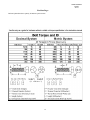
1
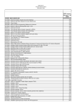
400 W. Artesia Blvd. Compton, CA 90220 Fax: (310) 747-3912 Ph: 1-800-776-0767 E-Mail: [email protected] Website: www.procompusa.com Latest Revision: 7.27.2013 PRO COMP SUSPENSION Part #52205 / 52205MX 2004 FORD F-150 2WD Attention: New Ford spindle nuts, part number 4L3Z3C294-AA are required. This document contains very important information that includes warranty information and instructions for resolving problems you may encounter. Please keep it in the vehicle as a permanent record. 52205/ 52205MX revised Box 1 of 4-PN 52205-1 Part # Description 7.27.13 Qty. Illus. Page 90-3226 2004 FORD F150 REAR CROSSMEMBER 1 4,5 8 90-2319 COMPRESSION STRUT 2 10 11 13-90390 U BOLT 4 C 13 20-65302 9/16" HARDWARE PACK: U-BOLTS 1 C 13 90-2144 REAR BUMP STOP EXTENSION 2 - - 95-300F 3" ALUMINUM BLOCK 2 C 13 90-6299 HARDWARE PACK: FRONT BRAKE LINE DROP 70-0311001500 5/16" X 1" GR 5 HEXBOLT 72-03100100512 5/16" NYLOCK NUT 73-03100030 5/16" SAE FLAT WASHER 1 2 2 4 - - 90-3058 SWAY BAR DROPS 2 7 9 90-1955 2004 F150 EMERGENCY BRAKE BRACKET 1 B 13 90-3272 2006 EMERGENCY BRAKE BRACKET 1 - - 90-6422 HARDWARE PACK: E– BRAKE BRACKET 70-0501501500 1/2” X 1 1/2” HEX BOLT 73-05000530 1/2” SAE WASHERS 72-050100512 1/2” NYLOC NUT 1 1 2 1 - - 90-6489 HARDWARE PACK: DRVR SIDE BRAKE LINE BRACKET 90-3613 BRAKE LINE RELOCATION PLATE 90-6024 HARDWARE PACK: 10-24 X 3/4" HEX BOLT PLATED 10-24 NYLOCK NUT FLAT WASHERS PLATED 171006ERL ADEL CLAMP 1 1 - - 1 1 2 1 - - Box 2 of 4-PN 52205-2 90-4104 SPINDLE DRIVER 2WD 1 - - 90-4105 SPINDLE PASSENGER 2WD 1 - - 1 8 4 10 10 10 11 11 11 A - 12- Box 3 of 4-PN 52205-3 90-6263 HARDWARE PACK: COMPRESSION STRUT BUSHINGS 15-11148 BUSHING, URETHANE 90-2109 SLEEVE, COMPRESSION STRUT 90-6314 HARDWARE PACK: REAR BRAKE LINE DROP /BUMP EXT 1 70-0311001800 5/16-18 x 1 HEX CAP SCREW GR. 8 Z-YELLOW 1 72-031100816 5/16-18 UNITORQUE NUT GR. C Z 1 73-03100838 5/16 USS FLAT WASHER ZINC 2 70-0371501800 3/8-16 X 1 1/2 HEX CAP SCREW GR. 8 Z-YELLOW 2 72-037100816 3/8-16 UNITORQUE NUT GR. C Z 2 73-03700034 3/8 HARDENED FLAT WASHER F436 SAE Z-YELLOW 4 2 52205/ 52205MX revised 7.27.13 Part # Description Qty. Illus. Page 90-6315 HARDWARE PACK: SWAY BAR DROP 70-0431751800 7/16-14 x 1 3/4" HEX CAP SCREW GR. 8 Z-YELLOW 72-043100816 7/16-14 UNITORQUE NUT GR. C Z 73-04300830 7/16 SAE FLAT WASHER ZINC 1 4 4 8 7 - 9 - 90-1915 2 10 11 90-6313 HARDWARE PACK: 2004 F150 CROSSMEMBER .180CNUCZ 18MM STOVER .180NWHDZ 18MM WASHERS 1 4 4 6 - 9 - 90-6324 HARDWARE PACK: 90-1974 ECCENTRIC CAM BOLT 1 4 6 9 90-6234 HARDWARE PACK: COMPRESSION STRUTS 70-0501251800 1/2"-13 X 1 1/4" GR 8 HEX BOLT 70-0504001800 1/2"-13 X 4" GR 8 HEX BOLT 72-050100816 1/2"-13 GR 8 STOVER NUT 73-05000034 1/2" SAE HARDENED FLAT WASHER 1 2 4 4 10 10 - 11 - 90-6317 HARDWARE PACK: SPACER MOUNT 72-043200810 7/16-20 GR. 8 PLATED HEX NUT 73-04300830 7/16 SAE FLAT WASHER ZINC 73-04300836 7/16 SPLIT LOCK WASHER 1 6 6 6 8a,8b,9 - 10 - 90-6319 HARDWARE PACK: ZIP TIES 10999 ZIP TIE, 11", BLACK 1 12 - - 90-6361 HARDWARE PACK: 73-07500834 3/4" HARDENED FLAT WASHER 1 1 B 2004 F150 COMPRESSION STRUT NUT PLATE 90-1083 REAR BRAKE LINE DROP 1 A 12 90-55089-3 FRONT BRAKE LINE EXTENSION (PASS) 1 - - 90-55089-4 FRONT BRAKE LINE EXTENSION (DRIVER) 1 - - 90-1104 COMPRESSION STRUT MOUNT 2 10 11 90-3230 F150 FRONT CROSSMEMBER 1 3,5 7,8 1 - - - 90-6393 HARDWARE PACK: BRAKE LINE DROP (2005 MODEL) 90-3202 BRAKE LINE DROP Box 4 of 4-PN 52205-4 927504 9000 SERIES SHOCK (REAR) 2 - - 90-2473 COIL SPACER 2 8b 10 3 13 52205/ 52205MX revised 7.27.13 Introduction: This installation requires a professional mechanic! We recommend that you have access to a factory service manual for your vehicle to as- sist in the disassembly and reassembly of your vehicle. It contains a wealth of detailed information. Prior to installation, carefully inspect the vehicle’s steering and driveline systems paying close attention to the tie rod ends, ball joints, wheel bearing preload, pitman and idler arm. Additionally, check steering-to-frame and suspension-to-frame attaching points for stress cracks. The overall vehicle must be in excellent working condition. Repair or replace all worn or damaged parts! Read the instructions carefully and study the illustrations before attempting installation! You may save yourself a lot of extra work. Check the parts and hardware against the parts list to assure that your kit is complete. Separating parts according to the areas where they will be used and placing the hardware with the brackets before you begin will save installation time. Check the special equipment list and ensure the availability of these tools. Secure and properly block vehicle prior to beginning installation. ALWAYS wear safety glasses when using power tools or working under the vehicle! Use caution when cutting is required under the vehicle. The factory undercoating is flammable. Take appropriate precautions. Have a fire extinguisher close at hand. Foot pound torque readings are listed on the Torque Specifications chart at the end of the instructions. These are to be used unless specifically directed otherwise. Apply thread lock retaining compound where specified. Please note that while every effort is made to ensure that the installation of your Pro Comp lift kit is a positive experience, variations in construction and assembly in the vehicle manufacturing process will virtually ensure that some parts may seem difficult to install. Additionally, the current trend in manufacturing of vehicles results in a frame that is highly flexible and may shift slightly on disassembly prior to installation. The use of pry bars and tapered punches for alignment is considered normal and usually does not indicate a faulty product. However, if you are uncertain about some aspect of the installation process, please feel free to call our tech support department at the number listed on the cover page. We do not recommend that you modify the Pro Comp parts in any way as this will void any warranty expressed or implied by the Pro Comp Suspension company. If you use traction bars, MX6 shocks may hit the traction bar mount, if it does a ES9000 Series shock should be used. Special Tools: Please refer to your service manual for more information. A special removal tool is required for safe removal of the tie rods. (PN T64P-3590-F). These tool may be purchased at your local Ford dealer. You may be able to rent any of these tools at your local parts store. 4 52205/ 52205MX revised Important! 7.27.13 Due to differences in manufacturing, dimensions and inflated measurements, tire and wheel combinations should be test fit prior to installation. Tire and wheel choice is crucial in assuring proper fit, performance, and the safety of your Pro Comp equipped vehicle. For this application, a wheel not to exceed 8” in width with a minimum backspacing of 4.5” to a maximum 5”, additionally, a quality tire of radial design, not exceeding 35” tall X 13.5” wide is recommended. Please note that the use of a 35” X 13.5” tire may require fender modification. Violation of these recommendations will not be endorsed as acceptable by Pro Comp Suspension and will void any and all warranties either written or implied. Please Note: Front suspension and head light realignment is necessary! Speedometer and ABS recalibration will be necessary if larger tires (10% more than stock diameter) are installed. Always use NEW cotter pins on re-assembly! (These items are NOT supplied) IT IS ADVISABLE THAT YOU HAVE HELP AVAILABLE WHEN INSTALLING THIS KIT. SOME COMPONENTS ARE HEAVY AND AWKWARD. ADDITIONAL HELP IS GOOD INSURANCE AGAINST INJURY! New Ford spindle nuts, part number 4L3Z-3C294-AA are required. IMPORTANT: Upon the installation of the rear portion of this kit, if the driveshaft is too short and does not properly engage the transfer case output shaft, driveshaft spacer kit (90-4107b) can be purchased separately and installed. NOTE: The use of this driveshaft spacer is intended for light usage only. If the intended usage is for high speed off road, this spacer should not be installed. The factory rear driveshaft should be lengthened by a qualified driveline shop. Equipment Available from your Pro Comp Distributor! Traction Bars (X-tra cab 4WD): Mounting kit: 72095, Bars: 72500 Traction Bars (Super Crew cab): Mounting kit: 72096, Bars: 72500 Coil over front shock kit: 52207MX (2WD) Add a leaf kit 13134 4” Lift Block /w Bump Stop: 95-404FB 5 1/2” Lift Block /w Bump Stop: 95-554FB Ford Spindle Nut (PACK OF TWO) 90-4116b Rear End Shin Kit 52700 MX6 Rear shock: MX6079 (2WD) MX-6R Reservoir Rear shock: MX6066R (2WD) MX-6R Reservoir Mounting Kit: 63012 and 63013 Rear Driveshaft Spacer: 91-4107B Also, Check out our outstanding selection of 5 tires to compliment your new installation! 52205/ 52205MX revised 7.27.13 Front Installation: 1. Prior to installing this kit, with the vehicle on the ground. Measure the height of your vehicle. This measurement can be recorded from the center of the wheel, straight up to the top of the inner fender lip. Record the measurements below. LF: RF: LR: RR: from the spindle. 9. Using the appropriate tool, remove the tie rod end nut and carefully separate from the spindle. 10.Remove the upper ball joint nut from the spindle and carefully separate using the appropriate tool. 11. Remove the lower ball joint nut, carefully separate using the appropriate tool. Remove the spindle from the vehicle set the spindle aside. 12. Remove the nuts from the sway bar links on the lower a arm. 13. Remove the three nuts from the top of the coil over assembly and the one large nut and bolt on the bottom. Remove the coil from the vehicle. 14. Remove the two bolts that retain the lower a-arms and remove them from the truck. 15. Repeat on the other side of the vehicle. 16. Mark the orientation in the truck and remove the sway bar and brackets. 2. Ensure that your work space is of adequate size and the work surface is level. Place your floor jack under the front cross member and raise vehicle. Place jack stands under the frame rails behind the front wheel wells and lower the frame onto the stands. Remove the jack and set the emergency brake, and place blocks both in front of and behind the rear wheels. Remove the front wheels. 3. Remove any skid plates and debris shields as necessary. 4. Work on one side of the vehicle at a time. 5. Remove the front calipers Illustration 1 from the front disks by reView from rear moving the 2 retaining bolts. NOTE: Make sure you do not let the calipers hang on the brake lines or damage will occur. 6. Remove the cotter pin, retainer and nut from the spud. Remove the front rotor and set aside. 7. Remove the anti-lock wiring and sensor from the spindle if applicable. Factory rear cross member brace 8. Remove the dust shields 6 52205/ 52205MX revised 7.27.13 17. Remove the rear cross member tion and attach the factory sway bar brace; retain the bolts and nuts for reand mounts to the new drop brackets. use. See illustration 1. 27. Swing the sway bar ends up into po18.Remove the oil filter drip tray. sition and loosely connect them to the 19. Install the front cross member 90a-arms, do not tighten until the truck is 3230 into original front A-arm mounton the ground. ing locations, using the factory bolts 28. Torque the sway bar mount hardware with the heads to the front, leave to 60 ft./lbs. loose. Make sure the cam guides face 29. WITH THE COIL OVERS install the the rear of the truck. See illustration new Pro-Comp coil over shock to the upper bracket 90-1977 with the sup3. 20. Install the rear cross member 90plied 1/2” X 2 3/4” hardware from pack 3226 into the frame with the factory 90-6318. Fasten upper bracket to bolts. The heads will face the rear of truck using the supplied 7/16” hardthe truck. See illustration 4. ware on the top. See illustration 8a 21. Install the lower a-arms into the new and 9. cross members with the supplied cam 30. WITH THE COIL SPACERS. Attach bolts 90-1974, washers and nuts. The the spacer 90-2473 to the top of the cams should fit between the cam shock using the factory hardware. guides on the cross members. Center Torque to factory specifications. With the cams in the guides. You will the notch in the bottom ring facing the torque the bolts at the end of the inoutside of the truck. Fit the shock and stall when the vehicle is on the spacer into the stock mountground. See illustration 6. ing locations. Fasten using Illustration 3 22. Torque the front and rear Drivers side view cross member mounting bolts to 135 ft./lbs. 23.Tighten all of the remainOE BOLT ing hardware to factory specifications. 24. Install the front sway bar drop brackets 90-3058 to the frame using the factory sway bar mounting hardware. Leave loose. See illustration 7. 25. Insert the 7/16” bolts, head up, with the washers from pack 90-6315 into the sway bar drops. See illustration 7. 26. Flip the sway bar over from its original orienta90-3230 FRONT CROSSMEMBER 7 52205/ 52205MX revised 7.27.13 dles. Carefully torque all of the hardware to factory specifications and replace any necessary O.E. hardware. 35. Support lower Aarms. Position new front spindles. Attach spindle to lower ball joint. Torque to 111 ft/lbs. 36. Attach the spindle to the upper ball joint. Torque to 85 ft/lbs. 37. Turn tie rod end 180 degrees and fasten tie 90-3226 REAR rod end to the spindle CROSSMEMBER and Torque to 111 ft/lbs. 38.Connect the anti-lock wiring harness and sensor to the spindle if applicable. 39. Repeat the installation on the other side of the vehicle. 40. Install the front rotors on to the front hub. Install the retainer nut and cotter OE BOLT Illustration 4 View from rear the supplied 7/16” hardware from pack 90-6317. See illustration 8b. 31. Install the OE bolt through the lower shock mount and a-arm. Torque to factory specifications. 32.ON THE DRIVER’S SIDE ONLY, locate and remove the inner most nut that secures the strut spacer to the frame and install the brake line relocation plate 90-3613 from pack 90-6489. See enclosed instructions for details. 33.Torque the 7/16” hardware. 90-3230 34. Transfer all the parts from FRONT the factory spindles to the CROSSsupplied Pro-Comp spinMEMBER 8 Illustration 5 View from rear 90-3226 REAR CROSSMEMBER 52205/ 52205MX revised 7.27.13 Illustration 6 Drivers side view CAM BOLTS 90-1974 18MM HARDWARE 6393. Carefully unbolt and bend the factory metal brake lines to allow them to be bolted to the bottom of the brake line drops 90-3202. WARNING:Make sure the brake lines that you just modified are still in the Ford factory plastic retainers attached to the inside of the frame and that they are not resting against any moving parts. 42. Install the bushings and sleeves from hardware pack 90-6263 into the compression struts 90-2319. See illustration 10. pin. Torque to 295 ft./lbs. 41. Install the front calipers on to the front rotors by reinstalling the retaining bolts. Torque to factory specifications. 42. Remove stock brake line bracket from frame. Remount bracket with the supplied brake line drops 90-55089-3 (PASS) and 90-55089-4(DVR) in between bracket and frame. Use factory hardware to fasten the shorter end of the bracket to the frame. Position the drops, best for your application. Use the supplied hardware from pack 90-6299 to fasten OE bracket to the new brake line drop. NOTE: 2005 models produced after 11/04 may require the use of longer brake line drops 903202 from hardware pack 90- Illustration 7 OE bolt plate Drivers side view 90-3058 SWAY BAR SPACER 90-6315 7/16” HARD WARE 9 52205/ 52205MX revised 7.27.13 Illustration 8a With coil over Illustration 8b 90-6317 7/16” nut, lock and flat washer With coil spacer 90-6317 7/16” nut, lock and flat washer 90-1977 COIL MOUNT 90-2473 SPACER Notch to outside 1/2" X 2 3/4” BOLT OE HARDWARE 90-2433 SPACER FACTORY COIL OVER PRO-COMP COIL OVER OE BOLT OE BOLT 90-2434 SPACER Illustration 9 With coil over 43. Install compression struts into mounts on the rear cross member using supplied 1/2” X 4” hardware. See illustration 10. 44. Place the supplied nut plates 901915 inside the transmission cross member and attach mounts 90-1104 using the supplied 1/2” X 1 1/4” hardware. See illustration 10. 45. Rotate the compression struts up and secure them to the mounts using the supplied 1/2” X 4” hardware. 46. Recheck all hardware for proper installation and torque at this time. 47. Reinstall the wheels and tires and lower the vehicle to the ground. Torque the factory wheels to 150 ft/ lbs. If you are using aftermarket wheels follow the manufacturers rec- 90-6317 7/16” nut, lock and flat washer 90-1977 COIL MOUNT PRO-COMP COIL OVER 10 52205/ 52205MX revised 7.27.13 Illustration 10 Compression struts 1/2” X 4” BOLT 90-2109 SLEEVE 90-2319 15-11148 BUSHING 90-1915 NUT PLATE 1/2” X 1 1/4” BOLT 90-1104 ommended specifications. 48. Torque sway bar end links to the lower control arm to 66 ft/lbs. 49.Torque the 18MM cam bolts to 180200 ft/lbs. 50. Recheck the wheel lug torque on all four wheels at this time. 51. On both sides of the vehicle, check the routing of the brake lines and the ABS wire harnesses. There must be no pinching, rubbing, or stretching of either component. Use zip ties to secure these items to the steering components. At full droop, cycle the steering from lock to lock while observing the reaction of these components. Reposition them if needed. 52. On completion of the installation, have the suspension and headlights re-aligned. 53. After 100 miles recheck for proper torque on all newly installed hardware. 54. Recheck all hardware for tightness after off road use. 11 52205/ 52205MX revised 7.27.13 IMPORTANT: Upon the installation of the rear portion of this kit, if the driveshaft is too short and does not properly engage the transfer case output shaft, driveshaft spacer kit (90-4107b) can be purchased separately and installed. NOTE: The use of this driveshaft spacer is intended for light usage only. If the intended usage is for high speed off road, this spacer should not be installed. The factory rear driveshaft should be lengthened by a qualified driveline shop. Rear Installation: brake line bracket from the inside of the frame. 1. Block the front tires and raise the rear of the vehicle. Support the frame with jack stands forward of the rear springs. 5. Install the supplied brake line extension bracket, 90-1083, to the frame using the OE hardware. Then bolt the factory bracket to the new bracket using the supplied 5/16” hardware from hardware pack 90-6314. See Illustration A. 2. Remove the rear wheels. 3. Remove the shocks on both sides of the vehicle. It may be necessary that you slightly raise the axle to unload the shocks for removal. 6. Reroute rear ABS as necessary use the supplied zip ties to secure lines. 4. On drivers side, unbolt the existing 7. Support the rear axle with a floor jack and remove the U-bolts on the driver side. Loosen the U-bolts on the passenger side. 90-1083 8. Install the lift block (95-300F) under the leaf spring on the axle pad, making sure the pins are fitted into the holes on the spring perch. Use your floor jack to raise the axle to the spring making sure the tabs on the factory leaf fit into the holes on the new lift block. Illustration A Rear brake line drop 5/16” 8. Secure the assembly with the supplied U-bolts (13-90390) and new high-nuts and washers from hardware pack 2065302. Do not tighten the U-bolts at this time. See Illustration C. NOTE: Make sure the block sits flush on the axle perch. 9. Repeat the installation on the other side of the vehicle. 10. When the installation of the remaining 12 52205/ 52205MX revised 7.27.13 side is complete, torque the U-bolts to 95 ft. lbs. If desired, excess of 1” can be trimmed from the u-bolt. Illustration B 3/4 WASHER Emergency brake line drop 11.Remove the factory bump stops. 12.Locate PN 90-2144, rear bump stop extension. Install this extension into the originals location using factory bolts. Using the bump stop previously removed, install it to the bump stop extension bracket using supplied 3/8” hardware from pack 90-6314 . NOTE: You may need to trim off the factory location tab on the bump stop. 90-1955 DROP BRACKET OE BOLT drop bracket PN 90-3272 to the frame using the OE retaining nut with the supplied 3/4” washer from hardware pack 90-6323 under the bracket. Secure the rear hole in the bracket using the 1/2” X 1 1/2” bolt and hardware from pack PN 906422 Torque the retaining nut to 222 ft. lbs. 13. Insert the supplied 60859 sleeves in both end of the shocks. (They will be located in the shock boxes.) 14. Install your new Pro Comp shocks (MX6079 either way or the 927504 w/ shaft end up) and torque this hardware to 66 ft. lbs. 17. Reinstall the wheels and tires and lower the vehicle to the ground. Torque 15. Remove the factory emergency brake bracket from the truck by removing the OE hardware. Unhook emergency brake cable and remove from factory bracket by pinching the tangs on the line. 16.Slip the cable through new bracket PN 90-1955 for 2004/2005 model and reconnect the emergency brake cable. Attach the supplied brake line drop bracket to the frame using OE hardware with the supplied 3/4” washer from hardware pack 90-6323 under the bracket. Torque the retaining nut to 222 ft. lbs. See Illustration B. For the 2006 model attach the supplied brake line Illustration C Block install U BOLT 13-90390 95-300F LIFT BLOCK OPTIONAL TRACTION BAR MOUNT SHOWN 13 52205/ 52205MX revised 7.27.13 the factory wheels to 150 ft/lbs. If you are using aftermarket wheels follow the manufacturers recommended specifications. 18. Recheck the wheel lug torque on all four wheels at this time. 19. Recheck all hardware for proper installation and torque at this time. 20. On completion of the installation, have the suspension and headlights realigned. 21. After 100 miles recheck for proper torque on all newly installed hardware. 22. Recheck all hardware for tightness after off road use. 14 52205/ 52205MX revised 7.27.13 Revision Page: 7.27.13: Updated hardware quantity in hardware pack 90-6489. 15 The PRO COMP PROMISE WARRANTY At Pro Comp, we know you have many choices when selecting products to personalize your vehicle. You should demand nothing but the highest quality available and have total confidence that the products you selected are the best in the industry. It is for these reasons that Pro Comp Suspension products are backed by the best warranty in the industry...the Pro Comp Promise! Pro Comp promises that its products will last a lifetime or we will replace it free of charge. It’s that simple! Because of our commitment to quality and manufacturing excellence, we are able to stand behind our products. FOREVER. It is Pro Comp’s Promise that if one of our suspension products breaks not due to misuse, neglect or vandalism, we will replace it. Whether you are the original purchaser or not, you can be assured that we will make it right. The Pro Comp Promise covers all suspension products including shocks and steering stabilizers. Buy Pro Comp Suspension today and enjoy it for the rest of your life! That’s our Pro Comp Promise! Notice to Owner, Operator, Dealer and Installer: Vehicles that have been enhanced for off-road performance often have unique handling characteristics due to the higher center of gravity and larger tires. This vehicle may handle, react and stop differently than many passenger cars or unmodified vehicles, both on and off–road. You must drive your vehicle safely! Extreme care should always be taken to prevent vehicle rollover or loss of control, which can result in serious injury or even death. Always avoid sudden sharp turns or abrupt maneuvers and allow more time and distance for braking! Pro Comp reminds you to fasten your seat belts at all times and reduce speed! We will gladly answer any questions concerning the design, function, maintenance and correct use of our products. Please make sure that the Dealer / Installer explains and delivers all warning notices, warranty forms and instruction sheets included with Pro Comp product. Warranty and Return Policy: Pro Comp warranties its full line of products to be free from defects in workmanship and materials for the life of the product. Pro Comp’s obligation under this warranty is limited to repair or replacement, at Pro Comp’s option, of the defective product. Any and all costs of removal, installation, freight or incidental or consequential damages are expressly excluded from this warranty. Pro Comp is not responsible for damages and / or warranty of other vehicle parts related or non-related to the installation of Pro Comp product. A consumer who makes the decision to modify his vehicle with aftermarket components of any kind will assume all risk and responsibility for potential damages incurred as a result of their chosen modifications. Warranty coverage does not include consumer opinions regarding ride comfort, fitment and design. Warranty claims can be made directly with Pro Comp or at any factory authorized Pro Comp dealer. IMPORTANT! To validate the warranty on this purchase please be sure to mail in the warranty card. Claims not covered under warranty * Parts subject to normal wear; this includes bushings, bump stops, ball joints, tie rod ends and heim joints. * Finish after 90 days. * Damage caused as a result of not following recommendations or requirements called out in the installation manuals. Pro Comp MX Series coil-over shocks are considered a serviceable shock with a one-year warranty against leakage only. Rebuild service and replacement parts will be available and sold separately by Pro Comp. Contact Pro Comp for specific service charges. Pro Comp accepts no responsibility for any altered product, improper installation, lack of or improper maintenance or improper use of our products. E-Mail: [email protected] Website: www.procompusa.com Fax: (310) 747-3912 Ph: 1-800-776-0767 PLACE WARRANTY REGISTRATION NUMBER HERE: __________________