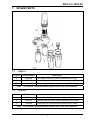
1
AFU-13 / AFU-25
Airline Filter Unit
User Instructions
Article No. 1034951
11. 2004
Issue B
AFU-13 / AFU-25
Airline Filter Unit
Contents
WARNINGS............................................................................................................................... ii
1.
INTRODUCTION ............................................................................................................ 1
1.1
BREATHABLE AIR.................................................................................................. 1
1.2
SUPPLY PRESSURE AND FLOW - DEMAND VALVE-FED.................................. 1
1.3
SUPPLY PRESSURE AND FLOW - CONSTANT FLOW ....................................... 1
1.4
PERSONNEL TRAINING ........................................................................................ 2
1.5
SERVICING............................................................................................................. 2
2.
TECHNICAL DESCRIPTION.......................................................................................... 2
3.
INSTALLATION AND OPERATING PROCEDURE....................................................... 3
3.1
CHECK COMPRESSOR / SUPPLY........................................................................ 3
3.2
PURGE AIR............................................................................................................. 3
3.3
CHECK HOSES ...................................................................................................... 3
3.4
CHECK APPARATUS ............................................................................................. 3
3.5
CONNECT SUPPLY................................................................................................ 4
3.6
CHECK SUPPLY PRESSURE AND FLOW ............................................................ 4
4.
SHUTTING DOWN PROCEDURE ................................................................................. 4
4.1
REMOVE BREATHING APPARATUS .................................................................... 4
4.2
ISOLATE / BLEED SUPPLY ................................................................................... 4
4.3
DISCONNECT HOSES / EQUIPMENT................................................................... 4
4.4
CLEAN, EXAMINE AND TEST EQUIPMENT ......................................................... 4
4.5
RECORD DETAILS OF USE................................................................................... 4
5.
CHECK AFU................................................................................................................... 5
5.1
CHECK SIGHT GLASS ........................................................................................... 5
5.2
CHECK VENTS ....................................................................................................... 5
5.3
CHECK HOUSING .................................................................................................. 5
5.4
CHECK PRESSURE GAUGE ................................................................................. 5
6.
ROUTINE MAINTENANCE ............................................................................................ 5
6.1
FIRST STAGE (AO) AND SECOND STAGE (AA) FILTER REPLACEMENT......... 5
6.2
THIRD STAGE (AC) FILTER REPLACEMENT....................................................... 6
7.
SPARE PARTS .............................................................................................................. 7
7.1
AFU-13 .................................................................................................................... 7
7.2
AFU-25 .................................................................................................................... 7
Sabre Breathing Apparatus is a division of Scott Health and Safety Limited.
Registered Office: Scott Health and Safety Limited, Pimbo Road, West Pimbo,
Skelmersdale, Lancashire, WN8 9RA, England.
i
WARNINGS
Please Read Carefully and Fully Understand
This manual is for use by personnel trained in the use and care of compressed-air airline
breathing apparatus, and MUST NOT be used as a self-teaching guide by untrained users.
Failure to understand or adhere to the AFU-13 / AFU-25 User Instructions may result in
injury or death.
Scott Health and Safety Limited have taken great care to ensure that the information in
this manual is accurate, complete and clear. However, Training and Technical Support
Services will be pleased to clarify any points in the manual and answer questions on
compressed-air airline breathing apparatus.
The following warnings are in accordance with certifying authority requirements and
apply to the use of breathing apparatus in general:
This equipment must only be used by persons fully trained in the use and
care of compressed-air airline breathing apparatus.
The quality of air used to supply compressed-air airline breathing apparatus
must meet the requirements of EN 12021 : 1999. The level of contaminants
shall not exceed the maximum permitted exposure level. Please refer to
National Regulations for guidance.
Scott Health and Safety Limited recommends that the air supply is regularly
tested to ensure compliance with these requirements.
AFU-13 and AFU-25 are only designed to remove water, oil and debris from
the air supply. AFU-13 and AFU-25 WILL NOT remove carbon monoxide
(CO), carbon dioxide (CO2) or other toxic gases or fumes from the air supply.
Ensure that the selection of equipment is sufficient for the tasks being
undertaken and the hazards likely to be encountered. Please refer to
National Regulations for guidance. Guidance can be found within the Health
and Safety Executive publication: HS-G(53) – Respiratory Protective
Equipment, a Practical Guide for Users.
Ensure that the air supply pressure and flow is sufficient with regard to the
number of apparatus wearers breathing from the supply. For further
guidance, please refer to Sections 1.2 and 1.3.
All breathing apparatus and breathable air supply equipment must be
regularly tested and maintained in accordance with National Regulations. In
the UK, equipment users should refer to the Health and Safety at Work Act
(1974), Pressure Systems and Transportable Gas Container Regulations
(1989) and the Personal Protective Equipment Directive (1993).
DISCLAIMER
Failure to comply with these instructions or misuse of the apparatus may result in: death,
injury or material damage, and invalidate any warranty or insurance claims.
COPYRIGHT
This manual must not be copied in part or whole, or used for purposes other than its intended
purpose without the written permission of Scott Health and Safety Limited.
ii
AFU-13 / AFU-25
1.2
1. INTRODUCTION
1.1
SUPPLY PRESSURE
AND FLOW - DEMAND
VALVE-FED
BREATHABLE AIR
Air used to supply breathing air may be
natural or synthetic. The composition of
breathable air is given in Table 1.
Component
Mass %
(Dry Air)
Volume%
(Dry Air)
Oxygen
23.14
20.948
Nitrogen
75.52
78.08
1.29
0.93
Argon
The airline supply pressure and flow must
meet the following requirements for use
with demand valve-fed apparatus’ being
supplied from a single source.
Carbon Dioxide
0.05
0.031 4
Hydrogen
0.000 003
0.000 05
Neon
0.001 270
0.001 818
Helium
0.000 037
0.000 524
Krypton
0.000 330
0.000 114
Xenon
0.000 039
0.000 009
Airflow
(L/min.)
1
5.0 – 9.0
300
2 (1 Pair)
5.0 – 9.0
450
3
5.0 – 9.0
750
4 (2 Pairs)
5.0 – 9.0
900
Generally,
each
additional
wearer
requires an extra 150 litres per minute,
each additional pair of wearers requires
300 L/min for one wearer and 450 L/min
for two wearers. All measurements must
be taken at the wearer end of the airline.
Table 1: Breathable Air
The dew-point of the air must be
sufficiently low to prevent internal
freezing.
used must
breathing
Supply
Pressure
(bar)
Table 2: Supply Pressure and Flow Demand Valve-Fed Apparatus
There is an increased fire risk when the
oxygen content is above the value shown.
The compressor oil
compatible
with
requirements.
No. of BA
Wearers
1.3
be
air
SUPPLY PRESSURE
AND FLOW - CONSTANT
FLOW
The airline supply pressure and flow must
meet the following requirements for use
with constant flow apparatus’ being
supplied from a single source.
The mineral oil content shall be such that
the supplied air is without the odour of oil.
The odour threshold is in the region of 0.3
3
mg/m .
Scott Health and Safety Limited
recommend that the purity and quality of
air used to supply breathing apparatus is
tested periodically in accordance with
National
Regulations;
and
further
recommend that a regular maintenance
and examination record is kept.
No. of BA
Wearers
Supply
Pressure
(bar)
Airflow
(L/min.)
1
5.0 – 9.0
300 – 500
2 (1 Pair)
5.0 – 9.0
600 – 1000
3
5.0 – 9.0
900 – 1500
4 (2 Pairs)
5.0 – 9.0
1200 – 2000
Table 3: Supply Pressure and Flow Constant Flow Apparatus
National regulations must be observed.
For each additional wearer, add a
minimum of 300 to 500 litres per minute.
All measurements must be taken at the
wearer end of the airline.
1
AFU-13 / AFU-25
1.4
PERSONNEL TRAINING
2. TECHNICAL
DESCRIPTION
Personnel who use compressed-air
airline breathing apparatus must be fully
trained in accordance with these
instructions and National Regulations.
The Sabre AFU is an Airline Filter Unit
designed to remove dirt particles, water
and oil from a breathable air supply for
use with compressed-air airline breathing
apparatus.
These instructions cannot replace an
accredited training course run by fully
qualified instructors in the proper and
safe use of Sabre compressed-air airline
breathing apparatus.
Sabre AFU is available in two sizes,
dependant upon the maximum flow-rate
required:
•
AFU-13 has a maximum flow
capacity of 13 litres per second (28
cubic feet per minute). This unit can
only be used to supply a maximum
of 3 wearers of demand valve-fed
apparatus or 2 wearers of constantflow apparatus.
•
AFU-25 has a maximum flow
capacity of 25 litres per second (53
cubic feet per minute). This will
allow up to 6 wearers (3 pairs) of
demand valve-fed apparatus or 4
wearers (2 pairs) of constant-flow
apparatus.
Please contact Training and Technical
Support Services or your distributor for
training course details.
Training and Technical Support
Services:
Scott Health and Safety Limited
Pimbo Road, West Pimbo,
Skelmersdale, Lancashire,
WN8 9RA, England.
Tel: +44 (0) 1695 711711
Fax: +44 (0) 1695 711775
1.5
SERVICING
In
order
to
maintain
optimum
performance, AFU-13 and AFU-25 must
be tested regularly and serviced at
scheduled intervals by personnel who
have completed a formal training course
and hold a current certificate for the
servicing
and
repair
of
Sabre
compressed-air
airline
breathing
apparatus.
These units are available either mounted
in a tubular steel floor stand or in a box
enclosure suitable for wall-mounting.
All units work on the same principle,
utilising a three-stage filtration system.
The first stage AO Filter is a highefficiency coalescing filter for the removal
-6
of dirt particles down to 1 x 10 metres in
size.
Instructions for the replacement of filter
elements are contained within this
manual. All other instructions for servicing
are contained in the Sabre Service
Manual, copies of which can only be
obtained by registered holders of a
current certificate.
The second stage AA Filter is a highefficiency coalescing filter for the removal
of oil mist/ water aerosol and dirt particles
-6
down to 0.01 x 10 metres in size with a
maximum remaining oil content of
3
0.01mg/m .
Your distributor or Training and
Technical Support Services will be
pleased to provide training course details
and quotes for service contracts. Please
see above for contact details.
An auto-drain valve is fitted to each of the
first and second stage filter housings to
allow water and other liquids to be safely
drained away.
The third stage AC Filter is an absorption
bed of activated carbon for the removal of
oil vapours and odours. The air supply
following this stage has a maximum
3
remaining oil content of 0.003mg/m at a
temperature of 21OC.
2
AFU-13 / AFU-25
The maximum unit inlet pressure is 10
bar. If the supply pressure exceeds this, it
will be necessary to fit an in-line regulator
and pressure relief valve (PRV) to protect
the AFU from over-pressurisation. A
pressure gauge on the inlet provides a
clear indication of the supply pressure.
3. INSTALLATION AND
OPERATING
PROCEDURE
The 3/8” BSP male inlet connection on
the pressure gauge can accommodate a
suitable supply hose or medium-pressure
airline coupling.
Check compressor inlet to verify that
there are no obstructions and ensure that
no exhaust fumes, vapours or other
contaminants enter the inlet connection.
The outlets are CEJN female couplings,
of which, two are provided on the AFU-13
and four on the AFU-25.
Ensure that the compressor is operating
correctly and not overheating.
3.1
WARNING:
•
The AFU WILL NOT remove
contaminants such as Carbon
Monoxide (CO), Carbon Dioxide
(CO2), or other harmful gases of
vapours.
•
If these or other harmful
gases/vapours are present, a
suitable air purifier MUST be
used.
•
If using cylinder supply, ensure
that sufficient air is available for
the anticipated tasks.
The filter elements are located in robust
metal housings fitted to a central yoke.
The housings may be removed by hand
to facilitate quick and easy replacement
of filter elements.
The first stage particulate filter has an
indicator fitted which changes from the
‘safe’ green mode to the red ‘warning’
mode when the filter element needs
replacing.
The recommended frequency of filter
element replacement is as follows:
Filter Element
Replace After
First Stage (AO Filter)
Maximum 6000 hours use
OR
Every 12 months
Second Stage (AA Filter)
Maximum 6000 hours use
OR
Every 12 months
Third Stage (AC Filter)
CHECK COMPRESSOR/
SUPPLY
3.2
PURGE AIR
Before installing the AFU to an airline
supply, purge the supply hose with air to
remove any water or loose debris which
may have become trapped within the line.
3.3
CHECK HOSES
Ensure that all supply hoses are of a type
approved for the supply of breathing air
and that they are clean and un-damaged.
Check the operation of all hose couplings
to ensure that they connect and
disconnect correctly.
Maximum 1000 hours use
OR
Every 2 months
Table 4: Frequency of Filter Element
Replacement
Note:
It may be necessary to change filter
elements more frequently if the airline
supply is heavily contaminated.
3.4
CHECK APPARATUS
Check the AFU to ensure that all
components are clean and un-damaged.
Any components showing signs of
damage should be replaced immediately.
Check
breathing
apparatus
and
associated equipment in accordance with
the manufacturer’s instructions, ensuring
that all components are clean and undamaged.
3
AFU-13 / AFU-25
3.5
CONNECT SUPPLY
4. SHUTTING DOWN
PROCEDURE
Connect breathing air supply to the AFU
inlet and ensure that the flow is in the
correct direction (indicated by an arrow on
top of the filters). Check that inlet
pressure does not exceed 10 bar.
4.1
All wearers must remove breathing
apparatus in accordance with the
manufacturer’s instructions.
CAUTION:
•
The AFU MUST be positioned
vertically or it will not function
correctly.
•
Ensure that the positioning of the
AFU is such that it is unlikely to
be damaged, tilted or overturned.
•
Ensure that the hose cannot
become kinked or constricted.
•
Check that the indicator on the
first stage filter is showing the
green ‘safe’ mode. Renew filter
element if the red ‘warning’
indicator is showing.
•
Listen for any audible leaks and
ensure that all hose connections
and filter retainers are secure.
Rectify faults immediately.
3.6
REMOVE BREATHING
APPARATUS
4.2
ISOLATE/BLEED
SUPPLY
Isolate the airline supply and release
pressure within the supply line using
bleed valve, (if fitted), or by venting
through the breathing apparatus.
4.3
DISCONNECT
HOSES/EQUIPMENT
Disconnect all hoses from equipment.
Coil all hoses and connect hose end
couplings for safe stowage.
4.4
CLEAN, EXAMINE AND
TEST EQUIPMENT
Clean and test all equipment thoroughly
and inspect for signs of wear or damage
in accordance with the manufacturer’s
instructions. All faults must be rectified
immediately.
CHECK SUPPLY
PRESSURE AND FLOW
Connect breathing apparatus supply hose
to the AFU outlet. Check that supply
pressure and flow at the extremity of the
hose, adjacent to the wearer, are in
accordance with the figures given in
Sections 1.2 or 1.3 of this manual (as
appropriate).
4.5
RECORD DETAILS OF
USE
A record must be maintained and kept
detailing the use of airline breathing
apparatus and associated equipment.
If the AFU inlet pressure is sufficient but
the hose outlet pressure is low, check to
ensure that the filters do not need
replacing. Replace the filters if required.
Information recorded usually includes:
1.
Name and address of the employer
responsible for the equipment.
2.
Particulars of the equipment used,
including details of the manufacturer,
model number or mark sufficient to
enable clear identification.
3.
Date of use and length of time the
equipment was in use.
4.
Date of the examination together
with the name, signature or unique
authentication mark of the examiner.
5.
Condition of the equipment and
details of any rectification work carried
out.
Once fully satisfied that the equipment is
functioning
correctly,
proceed
to
undertake the required tasks.
WARNING:
During use, the airline supply
equipment must be under constant
supervision in order to ensure that an
adequate air supply is maintained and
to alert wearers of potential hazards.
4
AFU-13 / AFU-25
5. CHECK AFU
5.1
6. ROUTINE
MAINTENANCE
CHECK SIGHT GLASS
6.1
Check sight glasses at the base of
housing to ensure that there is no trapped
liquid or dirt. The presence of liquid or dirt
indicates a malfunction of the auto-drain
valve. If this is the case, the AFU should
be sent for Servicing.
CAUTION:
DO NOT use solvents to clean any part
of the equipment.
Remove
and
clean
housings
in
accordance with the instructions shown
overleaf if dirt or liquids are trapped.
5.2
Note:
•
The numbers shown below in
brackets, eg (1), refer to item
numbers on the spare parts list
contained in Section 7 of this
manual.
•
For part number information, please
refer to Section 7 of this manual.
CHECK VENTS
Depress the small metal plunger on the
underside of housing and ensure that it
operates correctly, (there should only be
light spring-pressure resistance). If the
vent valve is sticking, the AFU must be
sent for Servicing. The weeping of liquid
from the vent valve indicates a
malfunction of the auto-drain valve. If this
is the case, the AFU should be sent for
Servicing.
5.3
The first and second stage filter elements
will operate indefinitely when only
removing liquids from the supply.
However,
the
build-up
of
solid
contaminants becoming trapped will lead
to a pressure drop across the filter
element, indicated by the red ‘warning’
indicator operating.
CHECK HOUSING
Check the housing for signs of abrasion,
corrosion or damage. If a fault is found,
the unit must be withdrawn from service
and the fault rectified in accordance with
the Service Manual.
5.4
FIRST STAGE (AO) AND
SECOND STAGE (AA)
FILTER REPLACEMENT
It is recommended that filter elements are
renewed after a maximum period of 6000
hours in use or every 12 months,
whichever is sooner.
CHECK PRESSURE
GAUGE
1.
Isolate the AFU from compressedair supply.
2.
Depress vent valve at the bottom of
housing to de-pressurise.
Check inlet pressure gauge to ensure that
it is un-damaged and functioning
correctly.
3.
Unscrew lower housing anticlockwise from yoke, (a warning whistle
will sound if the housing has not been
fully de-pressurised). If this occurs, retighten housing and repeat step 2 above
before re-commencing.
WARNING:
An inoperative pressure gauge may
result in hazardous dismantling of the
unit whilst it is still pressurised.
4.
Unscrew filter element (1) or (2)
and discard. Fit replacement element,
ensuring that replacement O-Ring is also
fitted. Ensure that filters are fitted in the
correct position, ie: AO Filter (1) is on the
left side, (as illustrated) and AA Filter (2)
is on the right.
5
AFU-13 / AFU-25
5.
Fit new O-Ring to filter housing.
Lubricate O-Ring with silicone grease if
required.
3.
Unscrew upper housing anticlockwise from yoke, (a warning whistle
will sound if the housing has not been
fully de-pressurised). If this occurs, retighten housing and repeat step 2 above
before re-commencing.
6.
Inspect inside of filter housings and
ensure that they are clean and undamaged. Clean housing using a warm
water and detergent solution. The sight
glass on the side of the housing indicates
whether the auto-drain unit is functioning
correctly. If dirt or liquid is present, check
to confirm if the unit is functioning
correctly. If the auto-drain unit is
malfunctioning, the AFU should be sent
for Servicing.
4.
Remove plug-in filter element (3)
and discard. Fit replacement element,
ensuring that replacement O-Ring is also
fitted.
5.
Fit new O-Ring to filter housing.
and lubricate O-Ring with silicone grease
if required.
6.
Inspect inside of filter housing and
ensure that it is clean and un-damaged.
Clean housing using a warm water and
detergent solution. Any signs of damage
or
corrosion
should
be
rectified
immediately.
7.
Once satisfied with the unit, re-fit
housing to yoke by turning in a clockwise
direction to secure. Tighten hand-tight
only. DO NOT over-tighten.
8.
Connect unit to a suitable airline
supply and pressurise to check for leaks.
7.
Once satisfied with the unit, re-fit
housing to yoke by turning in a clockwise
direction to secure. Tighten hand-tight
only. DO NOT over-tighten.
9.
Once completely satisfied that the
equipment is in good working order, it
may be returned to service.
6.2
8.
Connect unit to a suitable airline
supply and pressurise to check for leaks.
THIRD STAGE (AC)
FILTER REPLACEMENT
9.
Once completely satisfied that the
equipment is in good working order, it
may be returned to service.
CAUTION:
DO NOT use solvents to clean any part
of the equipment.
Note:
•
The number shown below in
brackets, ie (3), refers to the item
number on the spare parts list
contained in Section 7 of this
manual.
•
For part number information, please
refer to Section 7 of this manual.
The third stage filter element has a
recommended maximum service life of
1000 hours or 2 months, whichever is
sooner. The pressure differential will not
increase during this time, but the odour of
oil within the air will become more
prevalent.
1.
Isolate the AFU from compressedair supply.
2.
Depress vent valve at the bottom of
housing to de-pressurise.
6
AFU-13 / AFU-25
7. SPARE PARTS
7.1
AFU-13
Item No
Article Number
Description
1
1022103
First stage (AO) filter element complete with O-Rings
2
1022105
Second stage (AA) filter element complete with O-Rings
3
1022107
Third stage (AC) filter element complete with O-Rings
Note:
7.2
For all other component details, please refer to the Service Manual.
AFU-25
Item No
Article Number
Description
1
1022113
First stage (AO) filter element complete with O-Rings
2
1022115
Second stage (AA) filter element complete with O-Rings
1022109
Third stage (AC) filter element complete with O-Rings
3
Note:
For all other component details, please refer to the Service Manual.
7
Sabre Breathing Apparatus
Scott Health and Safety Limited
Pimbo Road, West Pimbo,
Skelmersdale, Lancashire,
WN8 9RA, England.
Tel: +44 (0) 1695 711711
Fax: +44 (0) 1695 711775