1
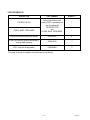
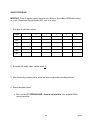
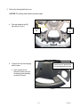
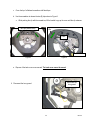
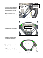
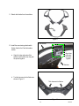
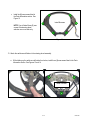
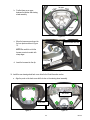
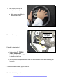
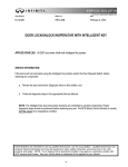
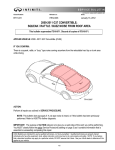
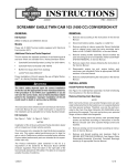
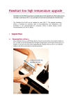
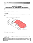
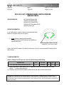
Classification:
Reference:
Date:
ST12-006
ITB12-050
August 14, 2012
EX35, G35, G37; STEERING WHEEL SWITCH FINISHER
SERVICE PARTS
APPLIED VEHICLES:
2007-2008 G35 Sedan (V36)
2009-2012 G37 Sedan (V36)
2008-2013 G37 Coupe (CV36)
2009-2013 G37 Convertible (HV36)
2008-2012 EX35 (J50)
SERVICE INFORMATION
If you confirm there is a need to replace the steering wheel switch
finisher on an Applied Vehicle for any reason:
•
Do not replace the steering wheel assembly.
The steering wheel switch finisher is now available as a
separate service part.
Steering Wheel Switch Finisher
(Example only - your vehicle may differ)
Refer to the Service Procedure in this bulletin for instruction on how to remove and install the steering wheel
switch finisher.
CLAIMS INFORMATION
Submit a Primary Part (PP) type line claim using the following claims coding:
DESCRIPTION
PFP
OP CODE
SYM
DIA
FRT
RPL ASCD SET/CANCEL/PHONE SWITCH
(1)
RM32AA
ZE
32
(2)
(1) Refer to the electronic parts catalog (FAST or equivalent) and use the Steering wheel part number
(48430-*****) as the primary failed part.
(2) Reference the current Infiniti Warranty Flat Rate Manual and use the indicated flat rate time.
Infiniti Bulletins are intended for use by qualified technicians, not 'do-it-yourselfers'. Qualified technicians are properly trained
individuals who have the equipment, tools, safety instruction, and know-how to do a job properly and safely. NOTE: If you believe
that a described condition may apply to a particular vehicle, DO NOT assume that it does. See your Infiniti dealer to determine if this
applies to your vehicle.
1/10
PARTS INFORMATION
DESCRIPTION
PART NUMBER
QUANTITY
COVER - BACK, STRG WHEEL
Refer to the electronic parts
catalog (FAST or equivalent) and
order the appropriate
FIN-STRG LID, RH
and
COVER - BACK, STRG WHEEL
1
SCREW (for attaching switches to finisher)
48469-JK00A
6*
SCREW (for attaching switches and finisher to
steering wheel assembly)
48469-JK10A
3
BOLT (for driver air bag module)
87850-8990A
2
FIN-STRG LID, RH
1
*Only three (3) screws are needed if the switches are on one side only.
2/10
ITB12-050
SERVICE PROCEDURE
IMPORTANT: Follow all cautions, warnings, and notes in the Electronic Service Manual (ESM) when working
on or near a Supplemental Restraint System (SRS), such as an airbag.
1. Write down all radio station presets.
Presets
1
2
3
4
5
6
AM
FM1
FM2
XM1
XM2
XM3
2. Disconnect both battery cables, negative cable first.
3. After disconnecting the battery cables, wait at least three minutes before proceeding with step 4.
4. Remove the steering wheel.
• Refer to section ST, STEERING WHEEL > Removal and Installation in the applicable ESM for
removal instructions.
3/10
ITB12-050
5. Remove the steering wheel back cover.
CAUTION: The steering wheel assembly has sharp edges.
a. Push and release the two (2)
clips shown in Figure 1.
Release
clip
Release
clip
Figure 1
b. To prevent the clips from snapping
back into place:
•
Insert trim tool to prevent clips
from snapping back into place
Insert a plastic trim tool
between the back cover and
the steering wheel assembly,
as shown in Figure 2.
Figure 2
4/10
ITB12-050
c. Cover the tip of a flathead screwdriver with fabric/tape.
d. Use the screwdriver to release the two (2) clips shown in Figure 3.
•
While pushing the clip with the screwdriver, lift the handle to pry up the cover until the clip releases.
Two clips (inside cover)
Clip
Push…
…and lift handle
Figure 3
Figure 4
e. Dispose of the back cover once removed. The back cover cannot be reused.
Disconnect the
horn ground
6. Disconnect the horn ground.
Figure 5
5/10
ITB12-050
7. Turn over the steering wheel assembly
and detach the harness from the clip.
Carefully move
harness to side
Detach harness
from clip
Next, move the harness to the side.
NOTE: Be careful to not let the
harness come into contact with sharp
edges.
Figure 6
Remove 3 screws
8. Remove the three (3) screws shown in
Figure 7.
Figure 7
9. Separate the switches and finisher
from the steering wheel assembly.
Remove 6 screws
10. Remove the six (6) screws shown in
Figure 8.
NOTE: You will remove three (3)
screws if the switches are on one side
only.
Figure 8
6/10
ITB12-050
11. Detach the finisher from the switches.
Figure 9
New finisher
12. Install the new steering wheel switch
finisher listed in the Parts Information
section.
Align holes
and posts,
then push
together
a. Align the holes and posts of the
switches and finisher, then the push
the pieces together.
Switches
Figure 10
b. Tuck the harness into the finisher as
shown in Figure 11.
Tuck harness into finisher
Figure 11
7/10
ITB12-050
c. Install six (6) new screws listed in
the Parts Information section. See
Figure 12.
Install 6 screws
NOTE: You will install three (3) new
screws if the steering wheel
switches are on one side only.
Figure 12
13. Attach the switches and finisher to the steering wheel assembly.
a. While holding up the switches and finisher from below, install three (3) new screws listed in the Parts
Information section. See Figures 13 and 14.
Install 3 screws
Figure 13
Figure 14
8/10
ITB12-050
No gaps
b. Confirm there are no gaps
between the finisher and steering
wheel assembly.
No gap
No gap
Figure 15
c. Move the harness up and over into
the horn plate as shown in Figure
16.
Insert harness into clip
NOTE: Be careful to not let the
harness come into contact with
sharp edges.
d. Insert the harness into the clip.
Horn plate
Figure 16
14. Install the new steering wheel back cover listed in the Parts Information section.
a. Align the posts on the back cover with the holes on the steering wheel assembly.
…with holes
Align posts…
Figure 17
Figure 18
9/10
ITB12-050
b. Push the back cover onto the
steering wheel assembly.
•
Apply pressure equally front to
back and side to side.
Figure 19
Reconnect the
horn ground
15. Reconnect the horn ground.
16. Reinstall the steering wheel.
• Refer to section ST, STEERING
WHEEL > Removal and
Installation in the applicable ESM
for installation instructions.
Figure 20
• Use the new driver air bag module bolts listed in the Parts Information section when reinstalling the air
bag module.
17. Reconnect the battery cables, negative cable last.
18. Reset the radio station presets.
10/10
ITB12-050