1
7/fV?
/v O /*
rfto
5 y Q /'f-stsZ
5 0 * * £ £££*
<h i $& & <**?££
CRUISE CONTROL
*
S ^ C eS
El
MR. tfF fP
Product
Service
Training
19006.00-4A
CRUISE CONTROL SYSTEMS
Foreword
This booklet is supplied by GM Product Service Training to GM dealer service personnel upon their com pletion of
the subject course conducted at GM Training Centers.
While this booklet will serve as an excellent review of the extensive program presented in the training center
session, it is not intended to substitute for the various service manuals normally used on the job. The range of
specifications and variation in procedures between carlines and models requires that the division service publica
tions be referred to, as necessary, when perform ing these operations.
All inform ation contained in this booklet has been furnished by AC Spark Plug Division and Cadillac Motor Car
Division, General Motors Corporation. The inform ation is based on the latest data available at the time of
publication approval. The right is reserved to make product or publication changes, at any time, w ithout notice.
This booklet, or any portion thereof, may not be reproduced w ithout written consent of GM Product Service
Training, General Motors Corporation.
Table of Contents
Page
Page
Non-resume Type Cruise Control........ . . . 1-1
111.
General O pe ra tio n .................................... . . . 1-1
Cruise System C om ponents................... ...1 - 3
Component F u n c tio n s ......................... ...1 - 3
Electrical and Vacuum O p e ra tio n .......... ...1 - 6
Electrical Operation ............................. . . . 1-6
IV.
Vacuum Operation ............................... ...1 - 7
System Diagnostics and S ervice........... . . . 1-10
1. Cruise System Inoperative ...........
1-10
2. Cruises Over/Under Set Speed . . .
1-12
3. S u rg in g ..............................................
1-13
Electrical System S c h e m a tic .................
1-15
Vacuum System Schematic ...................
1-19
Combined Electrical-Vacuum System
S c h e m a tic ..............................................
1-20
Resume Type Cruise Control..............
2-1
General O pe ra tio n ....................................
2-1
Cruise System C o m p on e nts...................
2-1
System Diagnostics and S ervice ...........
2-2
1. Cruise System Inoperative ...........
2-2
2. Cruises Over/Under Set Speed . . . . . . 2-2
3. S u rg in g .............................................. . . . 2-2
Electro-pneumatic System Schematic . . . . 2-6
V.
Aspirator Assisted Vacuum System
(J-car).....................................................
3-1
General O p e ra tio n ......................................
3-1
System Diagnostics ..................................
3-2
Vacuum System Schematic .....................
3-4
Vacuum Assisted Systems ...................
4-1
General Operation and Applications —
4-1
System Diagnostics .................................
4-2
Diesel Transducer, Non-Resume and
Resume Systems................................. . .. 5-1
Id e n tific a tio n .............................................. . . . 5-1
System Diagnostics ................................. .. . 5-1
VI.
Electronic Cruise Control..................... . . . 6-1
Non-D.F.I. and Computer Integrated
D.F.I., Cadillac .......................................... . .. 6-1
General Description ............................. . .. 6-1
Component O p e ra tio n ......................... . . . 6-2
Typical C ircuit Operation, Non-D.F.I—
. . . 6-8
Typical C ircuit Operation, D.F.I.............. .. . 6-13
Diagnosis, Non-D.F.I.................................. . . . 6-14
Cruise Diagnosis, D.F.I............................. . .. 6-18
I. Non-Resume Type Cruise
Control (1968-1980 models)
q
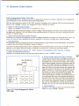
General Operation
The AC Cruisemaster System allows the driver to
maintain a constant highway speed w ithout having to
apply continual foot pressure to the accelerator pedal.
Selected cruise speeds are easily maintained. Speed
changes may be accom plished at w ill and override
features allow the vehicle to be accelerated, slowed
or stopped.
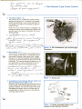
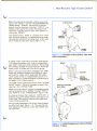
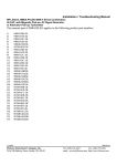
To engage cruise control, the driver merely acceler
ates to the desired cruise speed above 30 mph and
then fully depresses and slowly releases the control
switch button. For ease of operation, the control
switch button is located in the end of the turn signal
lever or gear shift lever (figure 1-1).
Figure 1-1, Non-Resume Type Cruise Control
Turn Signal Handle and Switch.
When engaged the cruise system controls throttle po
sition. Vehicle speed is maintained regardless of ter
rain changes. However, extremely steep hills, heavily
loaded vehicles and significant changes in altitude
may cause some variation in selected cruise speed.
1. DEPRESS FULLY TO DISENGAGE
2. PARTIAL RELEASE TO ENGAGE
3. FULL RELEASE, CRUISE REMAINS ENGAGED
Refer to figure 1 -2. When the control switch button is
held in the completely depressed position it w ill dis
engage the cruise control function. It will remain dis
engaged as long as held depressed. When the button
is partially released, it engages cruise control. When
the button is released the cruise control function re
mains engaged.
Some GM vehicles feature an “ ON-OFF” switch. On
these models, the cruise control function may be dis
engaged by placing the switch in the “ OFF” position.
Figure 1-2, Operation Control Positions.
■^O-ea-C
/I
p M Z k r , tX
a.
^
2 JL
ir "
a ^e
M
(
M
U
-
*
fi& Z O L A rv ft
1/ i f L O B
I. Non-Resume Type Cruise Control
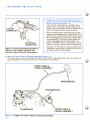
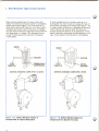
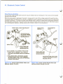
The cruise control function is disengaged whenever the brake pedal is depressed (figure 1 -3a). To re-engage the
cruise function, the driver merely accelerates to a speed above 30 mph and then fully depresses and slowly
releases the control switch button.
To cruise at a higher speed after cruise control has been engaged, the driver accelerates to the higher speed and
then fully depresses and slowly releases the control switch button.
To cruise at a lower speed, fully depress the control switch button and hold it until the vehicle has decelerated to
the desired lower speed. Slowly releasing the control switch button re-engages the cruise function.
When the cruise function is engaged, depressing the accelerator w ill override the system allowing vehicle speed
to increase (figure 1 -3b). Releasing the accelerator pedal allows speed to decrease until it reaches the previously
selected lower cruise speed. The cruise system will then autom atically maintain the previously selected speed.
Figure 1 -3a, The Brake Disengages the System.
Figure 1 -3b, The Accelerator Overrides the
System.
I. Non-Resume Type Cruise Control
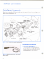
Cruise System Components
The major components of the AC Cruisemaster System are the engage switch, transducer assembly, servo and
linkage, vacuum and electric cruise release switches, the upper and lower cable and casing assemblies, wiring
harness and vacuum lines (figure 1-4).
Figure 1 -4, AC Cruisemaster System Components.
Component Functions
1. Cruise Control Switch (figure 1 - 5 ) . . .
This driver operated control is conveniently
mounted on the end of the turn signal handle or
the gear shift selector lever. The driver operated
functions of the cruise control switch have been
previously described in detail on page 1-1.
Figure 1-5, Cruise Control Lever with Engage
Switch Button.
1-3
—<1^-0-.
I. Non-Resume Type Cruise Control
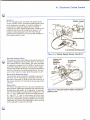
Transducer (figure 1 - 6 ) . . .
The transducer is a com bination speed sensing
device and control unit. It contains a low speed
switch that prohibits cruise control operation at
low speeds. This switch is calibrated at approxi
mately 30 mph.
SPEEDOMETER
CABLE
HOLD
ENGAGE
When the cruise control function is engaged, the
transducer senses vehicle speed and controls the
vacuum level to the servo to maintain the cruise
speed selected.
PO R T“B”
(TO MANIFOLD
VACUUM
SOURCE)
P O R T“A”
cs-^c-d>*z^L*\ ^ ¥ l-
1 ^s&-crc£y . y^C^jZ^rib
/
Figure 1-6, AC Cruisemaster (non-resume type)
Transducer.
Servo, (figure 1 - 7 ) . . .
The servo unit is connected to the carburetor by a
rod or linkage, a bead chain, or a Bowden cable or
com bination Bowden cable bead chain linkage.
The servo unit maintains desired vehicle speed by
receiving a controlled am ount of vacuum from the
transducer. This vacuum adjusts the tension on the
rod, bead chain or other connection to the car
buretor which controls throttle positioning.
&~y^
Figure 1-7, Servo unit.
4. Combination Cruise Release Electric Switch and
Vacuum Release Valve (figure 1-8). ..
Whenever the brake pedal is depressed the electric
cruise release switch disengages the system. As an
additional feature, the vacuum release valve also
disengages the system when the brake pedal is
pressed. Both of these controls are mounted on
the brake pedal bracket.
BRAKE PEDAL
BRACKET
BRAKE
PEDAL
Figure 1-8, Brake Activated Electric and
Vacuum Cruise Release Controls.
1-4
I. Non-Resume Type Cruise Control
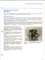
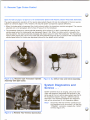
5. Com bination Vacuum Release Valve and Trans
m ission Lock-up Torque C onverter Clutch Switch,
Resume System Only (figure 1 - 9 ) . . .
1981 and later model vehicles, equipped with a
lock-up torque converter (locking clutch) trans
mission, use a com bination vacuum release valve
and cruise release electric switch assembly.
When the brake pedal is depressed, the vacuum
release valve disengages the cruise function. At the
same time the contacts in the electric switch open
which disengages the locking clutch mechanism in
the transmission. The locking clutch system w ill
remain disengaged after the brake pedal is re
leased. The system remains disengaged until the
electronic control module signals re-engagement.
1981 and Later Models Equipped with
Lock-up Torque Converter Transmission.
See figure 1 -9. Whenever the vacuum release valve
is adjusted it also adjusts the position of the lock
up torque converter clutch switch.
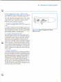
Upper and Lower Cable and Casing Assem blies (figure 1 - 1 0 ) ...
The upper cable and casing assembly connects the transducer to the speedometer. The lower cable and
casing assembly connects the transmission driven gear to the transducer.
I. Non-Resume Type Cruise Control
Electrical and Vacuum
Operation
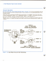
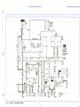
Figure 1-27 is a combined electrical-vacuum system schematic of the non-resume type cruise control system.
Figures 1-25 and 1-26 show the electrical and vacuum systems separately.
Electrical Operation
Open the fold-out page Electrical System Schematic, figure 1-25, page 1-15. The follow ing paragraphs de
scribe the electrical operation of the system. Trace and follow circu it operation on the schem atic drawing.
Current from the positive side of the “ BATTERY” (B +) flows through the “ IGNITION SWITCH” , “ FUSE” , closed
“ BRAKE RELEASE SWITCH” to the “ CRUISE CONTROL SWITCH” .
When the “ CRUISE CONTROL SWITCH” is in the “ AT REST” position, current flows through the switch, the “ 40
OHM RESISTANCE WIRE” and to the “ HOLD” terminal on the “ TRANSDUCER” . The voltage at the “ HOLD”
terminal is now quite low due to the voltage drop across the 40 Ohm resistance. This voltage is also applied to the
“ SOLENOID COIL” in the tra n s d u c e r. .. but it is not sufficient to energize this coil.
Low Speed Switch Operation (figure 1 - 1 1 ) . . .
The transducer contains a rubber clutch with an
operating arm. The clutch and arm rotate sim ilar to a
speedometer pointer needle. At speeds below approx
imately 30 MPH, the clutch arm holds the low speed
switch contacts open.
If the cruise control switch is depressed at speeds
under 30 MPH, the low speed switch contacts are held
open by the clutch arm . .. cruise can not be
engaged.
At speeds above about 30 MPH, the rubber clutch arm
rotates w hich allows the low speed switch contacts to
close (see dotted line, figure 1-11).
When the low speed switch contacts are closed, the
cruise system can now be engaged. The coil engages
with a distinct “ th u n k” sound.
Refer to the electrical schematic, figure 1-25. When
the engagement switch button is released, current
flow through the “ 40 OHM RESISTANCE WIRE” is suf
ficient to hold the “ SOLENOID” in the engaged
position.
Cruise Lamp . ..
Some models of the cruise system feature a “ CRUISE
LAMP” (figure 1-25). When the “ SOLENOID” is en
gaged it provides a ground for the cruise lamp. There
fore, when cruise control is engaged the cruise lamp
will illuminate.
Figure 1-11, Low Speed Switch Operating
Circuit.
I. Non-Resume Type Cruise Control
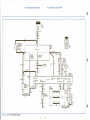
Vacuum Operation
Open the fold-out page, Vacuum System Schematic, figure 1-26, page 1-18. The follow ing paragraphs describe
the vacuum operation of the AC Cruisemaster system. Trace and follow the circu it operating description on the
schematic drawing.
Assume the vehicle is operating at 50 MPH and the cruise control is not engaged. Vacuum from the engine
manifold is blocked off at “ PORT B ” of the “ TRANSDUCER” (figure 1-12 “ VIEW A ” ). A cup shaped valve which is
part of the “ SOLENOID” assembly is positioned to block “ PORT B” (also see figure 1-11).
When the cruise control is engaged, the solenoid energizes, moving the cup shaped valve upward to also cover
“ PORT A ” (figure 1 -12 “ VIEW B” ). With both ports covered, common vacuum is developed across “ PORT A ” and
“ PORT B” .
“VIEW A”
PORT “B” BLOCKED,
CRUISE NOT ENGAGED
“VIEW B”
PORT “A” AND PORT “B”
COMMON VACUUM, CRUISE ENGAGED
Figure 1-12, Cup S haped Vacuum V alve Positioning
I. Non-Resume Type Cruise Control
When the solenoid is energized, engine vacuum ap
pears at the “ SERVO” and the “ VACUUM BRAKE RE
LEASE VALVE” . However, the amount of vacuum
present must be precisely controlled. “ PORT C” is a
variable orifice and is the control mechanism that
maintains or adjusts vacuum level in the system, in
cluding the “ SERVO” .
SLIDING VALVE
The variable orifice, “ PORT C” consists of an orifice
tube and valve assembly. It is essentially an air meter
ing valve that consists of a sliding valve, orifice tube
and a wishbone type clutch spring (figure 1-13).
RUBBER
CLUTCH
Figure 1-13, Variable Orifice (Orifice Tube and
Valve Assembly).
A rubber clutch is secured to a spindle shaft (figure
1 -13). When the system is not in use, a solenoid oper
ated “ CAM” mechanism (fold-out figure 1 -26) spreads
the wishbone shaped clutch spring which allows the
rubber clutch to rotate w ithin the clutch spring.
When cruise control operation is engaged, the “ CAM”
allows the wishbone shaped clutch spring to close
and hold the rubber clutch. Essentially the rubber
clutch works sim ilar to a speedometer pointer. It ro
tates clockwise or counterclockwise in proportion to
the speed of the rotating magnet.
The rubber clutch controls the motion of the “ SLIDING
VALVE” (figure 1-13) which changes the size of the
opening in the “ ORIFICE TUBE” .
When the cruise control function is engaged, engine
vacuum is applied to the “ SERVO” through “ PORT A ”
and “ PORT B” of the “ TRANSDUCER” (figure 1-26).
Air entering through the transducer “ AIR FILTER” is
metered through the preset window openings in the
orifice tube. The resulting vacuum level establishes
initial throttle positioning.
During initial engagement, the orifice tube windows
are about half open (figure 1-14). This opening has
been adjusted at the factory or by a repair station serv
ice technician.
Position, 1/2 Open.
1-8
I. Non-Resume Type Cruise Control
When vehicle speed drops, the valve moves and
makes the orifice tube windows smaller or completely
closes the windows (figure 1-15). This reduces or
shuts off the amount of bleed air to the servo which
increases the vacuum level in the servo. Increased
vacuum draws-in the servo diaphragm which pulls the
rod, bead chain or linkage. This increases the car
buretor throttle opening to maintain the desired
cruise speed.
Figure 1-15, Orifice Window Closes to
Compensate for Speed Reduction.
If vehicle speed tends to increase, such as on a
downgrade, the valve moves to increase the size of
the w indow openings in the orifice tube (figure 1 -16).
A larger volume of bleed air is admitted at the servo
which reduces the vacuum level. The servo dia
phragm relaxes the tension on the bead chain or link
age to reduce the carburetor throttle opening. In this
way, cruise speed is maintained on a downgrade.
Compensate for Speed Increase.
I. Non-Resume Type Cruise Control
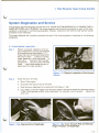
System Diagnostics and Service
The symptoms requiring diagnosis and service are A. CRUISE SYSTEM INOPERATIVE, B. CRUISES OVER or
UNDER SET SPEED and C. SURGING. The proper diagnosis and correction procedure for each of the three
symptoms is described in the follow ing paragraphs. However, reference to the vehicle model service manual
procedure is also necessary.
The proper diagnosis and correction procedure for each of the three symptoms is described in the follow ing
paragraphs.
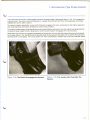
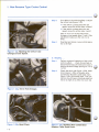
A. Cruise System In o p e rativ e . . .
Step 1
Perform a physical inspection of the en
gine compartment. Look for disconnected
or pinched vacuum hoses (figure 1 -1 7 ).. .
hoses that could be pinched closed when
the hood is down . . . cracked or spongy
hoses, especially in high heat areas . . . a
leaky servo . . . missing or disconnected
components . . . be sure to check manifold
fittin g . . . check brake pedal vacuum re
lease valve for proper operation.
Figure 1 -17, Physical Inspection of the Vacuum
System .
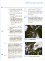
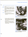
Step 2
Check the servo for leaks:
a.
Shut off the engine
b.
Disconnect the vacuum line at the servo
c.
Push the servo diaphragm fully inward and hold (figure 1-18a)
d.
Use a finger or thum b to tightly cover the servo vacuum fitting and release the diaphragm (figure
1-18b). The diaphragm should remain depressed. If it expands, a leak is present . . . replace the
servo unit.
Figure 1 -18a, Depress Servo Diaphragm.
Figure 1 -1 8b, Cover Vacuum Port and Release
Finger Pressure on Diaphragm.
I. Non-Resume Type Cruise Control
Step 3
Check for a blown fuse. If the fuse is good,
go to Step 4.
Step 4
Remove the electrical connection at the
transducer (figure 1-19). Reconnect so
that the “ ENGAGE” wire in the harness
mates with the “ HOLD” term inal on the
transducer. This bypasses the low speed
switch.
Step 5
Turn ignition switch “ ON” . Do not start
the engine. Slowly depress and slowly re
lease the cruise control switch. Listen for
a solenoid engagement “ th u n k ” “ th u n k ”
sound (figure 1 -20). If the “ th u n k ” is heard
on engagement and release, the solenoid
coil and related circuits are electrically
good. If the “ th u n k” is erratic or not heard,
go to Step 6.
Step 6
Check the brake activated electric release
switch. A “ h air-trigger” misadjustment
could be the cause of the problem. De
press brake switch in Vs-inch increments.
At each point attempt system engagement
with the cruise control switch until en
gagement is no longer possible. Pedal
travel for the engagement interval should
be about Vt-inch. Adjust the brake switch
as required. Note that the brake pedal can
“ hang-up” . This must be considered
whenever brake switch adjustment is
performed.
Figure 1-19, Reverse Electrical Connector
Harness to Bypass Low Speed Switch.
Figure 1-20, Pressing the Cruise Control Switch
Button should Engage the Solenoid.
If the transducer does not engage, per
form the follow ing basic electrical checks:
6a.
Check to make sure all electrical
connectors and term inals are free of
grime and corrosion.
6b.
See fold-out figure 1-25. Disconnect
the harness at POINT A. Connect a
voltm eter to the “ h o t” side at
POINT A.
I. Non-Resume Type Cruise Control
6c.
6d.
With the ignition on, battery voltage
should be indicated on the voltmeter.
If voltage is not shown go to 6d . . . If
voltage is present, go to 6e.
Step 9
Check fo r vacuum at PORT B (fold-out
figure 1-26). Repair as necessary.
Step 10
After required repairs or adjustments, re
connect all electrical connectors and vac
uum hoses. Then road test the vehicle. If
the system remains inoperative, replace
the transducer.
Use the voltm eter to measure the vol
tage at both sides of the BRAKE RE
LEASE SWITCH.
• If the voltage reading is the same,
the switch is closed and requires
no adjustment.
• If no voltage is measured on either
side of the switch, an open circuit
exists between the switch and bat
tery. Perform repairs as necessary.
• If battery voltage is present on one
side of the switch and not the
other, the switch requires
adjustment.
6e.
Reconnect the connector at POINT A.
Connect a voltm eter to the “ h o t”
side of POINT B with a small probe.
Go to 6f.
6f.
Depress the engagement switch half
way. Voltage should be present. If
voltage is not shown replace the en
gagement switch with a known good
switch and re-check. If no defect is
found go to 6g.
6g.
Disconnect the harness connector at
the TRANSDUCER. Connect a volt
meter to the “ h o t” side of POINT C at
the harness. Depress the engage
ment switch halfway. Battery voltage
should be present. If no voltage is
shown, repair the harness between
POINT B and POINT C. If no defect is
found, go to Step 7.
Step 7
If the solenoid will not engage and voltage
is present at point “ C” , disconnect the
connector at the TRANSDUCER and
measure for continuity between point “ E”
and ground with an Ohmmeter . . . resist
ance should read 5 to 6 Ohms. A lower
resistance reading requires replacement
of the transducer. If the resistance is
higher than 6 Ohms, check the transducer
casting to ground resistance. If the ground
is electrically good and the resistance re
mains high, replace the transducer. Also
check the 40 Ohm resistance wire from
point “ D” to point “ E” .
Step 8
If the electrical circuits have no defects,
check the vacuum system. First, place the
transm ission in Park, set the hand brake
and start the engine.
B. Cruises Over/Under Set Speed . ..
Step 1
Perform a general inspection of the cruise
control system. Check for pinched or dis
connected vacuum hoses and a loose or
binding or tig ht throttle linkage (figure
1 -21a and b). If the vehicle cruises consis
tently under the set speed, first look for a
vacuum leak.
Figure 1-21 a, Inspect Hoses.
Figure 1-21b, Inspect Throttle Linkage.
1-12
I. Non-Resume Type Cruise Control
____________________________________________________________ w
Step 2
If no defect is found during Step 1, adjust
the orifice tube (figure 1-22).
• If the vehicle
speed, screw
• If the vehicle
speed, screw
cruises below the set
the orifice tube outward.
cruises above the set
the orifice tube inward.
Each 1/3-inch turn of the orifice tube
changes cruise speed about 1-mph. After
adjustment make sure the lock nut is
snug.
Step 3
Road test and check cruise control opera
tion at 50 mph.
Figure 1-22, Adjusting the Orifice Tube
Changes Cruise Speed.
C. Surging . . .
Step 1
Perform a general inspection of the cruise
control system . .. check for pinched or
disconnected vacuum hoses and loose or
binding throttle linkage (see figure 1-21 a,
1-21b).
W
Step 2
Check the servo rod (figure 1-23a), bead
chain (figure 1-23b), or Bowden wire
combination Bowden cable bead chain
(figure 1-23c) for excess slack. This con
nection should have a minimum slack but
not be so tight as to affect hot curb idle.
Figure 1-23a, Servo Rod (linkage).
sJ
Figure 1-23b, Bead Chain.
1-13
Figure 1-23c, Bowden Wire Combination
Bowden Cable Bead Chain.
uulLA-P
I. Non-Resume Type Cruise Control
Step 3
Make sure the vehicle is equipped with the
correct transducer and servo . .. check
out the part number (figure 1-24).
Step 4
If surging remains, the most probable
cause is a restricted vacuum hose or fit
ting to PORT B on the TRANSDUCER.
Step 5
If no defect is found, replace the trans
ducer and road test the vehicle.
u * ■£>
^
7('f
tc ^ ry
er-r
Y
'
I
Non-Resume Type Cruise Control
Figure 1 -24, Check the Part Number for Vehicle
Application.
— NOTE —
If transducer repair is required, it m ust be per
form ed by an authorized tran sd u cer rep air facility
as listed in the applicable A C -D elco repair bulletins.
Figure 1-25, AC Cruisemaster system, Non-resume Type Electrical System Schematic.
K e y a ji_
( Ho l p - / n )
1-15
Non-Resume Type Cruise Control
I. Non-Resume Type Cruise Control
NOTES
1-16
1-17
i/
Ct^'/
X -X ^ •
^ 4 ^ 0 0 ^ ^ ^ e z r r -b -P
^b+ < i_G > r5>
sO & ^ e
.
I. Non-Resume Type Cruise Control
|
Non-Resume Type Cruise Control
NOTES
£<6^7 j^C ^n n yO _
ROTATION WITH
SPEED INCREASE
7^
>
oo
(Sri.7
•a .
PORT “C’
. ^
y
TO VACUUM
SOURCE
B R AK E
PEDAL
ARM
a
i a
TRANSDUCER
ao£L
VACUUM
RELEASE VALVE
J
SERVO
777777777777
THROTTLE
Figure 1-26, AC Cruisem aster System, Non-resum e Type Vacuum System Schem atic.
1-18
1-19
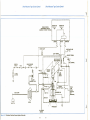
I. Non-Resume Type Cruise Control
I. Non-Resume Type Cruise Control
CRUISE CONTROL
(ENGAGEMENT) SWITCH
SHOWN IN “AT REST” POSITION
IGNITION
SWITCH
CRUISE
LAMP
CIRCUIT
(SOLENOID
NOT
ENERGIZED)
'7777777777,
THROTTLE
TRANSDUCER
TO VACUUM
SOURCE
Figure 1-27, Combined Electrical-Vacuum System Schematic.
1-20
1-21
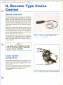
II. Resume Type Cruise
Control
General Operation
The AC Cruisemaster resume system with “ RESUME”
operates somewhat sim ilarily to the non-resume type
system. The major difference is that with the resume
feature, the driver may resume a pre-set speed after
the system has been disengaged by braking. This is
done by moving a slide switch on the cruise control
lever handle m om entarily to the “ Resume” position
(figure 2-1).
Note that the Off/On/Resume slider switch has three
positions. The switch turns the cruise control system
on and off. It also returns cruise control operation to
the last speed setting when placed in the “ Resume”
position. When the slider switch is in the “ O ff” posi
tion, set speed memory is canceled.
The cruise switch button, located in the end of the
m ultifunction lever, has three functions; 1. engage the
cruise mode, 2. a coast position which allows the
driver to decrease speed and 3. the normal or the fully
released position.
Figure 2-1, Resume Cruise Control Lever.
& N ~O
— NOTE —
Low speed switch e n g ag em en t ranges
from 30 to 40 mph. R efer to applicable
service m anual or bulletins.
SPEEDOMETER
CABLE
DRIVE
CABLE
ENGAGE
Cruise System
Components . . .
Cruise system components, with the exception of the
resume cruise control switch and transducer, are
sim ilar to the components discussed in Part I of this
service manual.
VACUUM
SOURCE
RESUME SOLENOID VALVE
Figure 2-2 is a resume type cruise control transducer.
Unlike the non-resume transducer, it features a re
sume solenoid valve and a special clutch
arrangement.
Figure 2-2, Resume Cruise Control Transducer.
II. Resume Type Cruise Control
Open the fold-out page 2-6, figure 2-9, AC Cruisemaster System with Resume, Electro-Pneum atic Schematic.
The electro-pneum atic operation of the resume type system (figure 2-9) can be compared to the non-resume
system for sim ilarity (figure 1-27). However, the resume system components operate differently.
• When the brake pedal is depressed, the clutch solenoid within the transducer remains energized. The resume
solenoid coil is not energized, which shuts off vacuum to the transducer.
• The transducer features a resume spindle assembly which allows it to retain a mechanical memory of the
vehicle speed when the brake pedal was depressed (figure 2-3a). When the slider switch is moved to the
resume position, the resume solenoid energizes and allows vacuum to enter the transducer. The mechanical
memory then adjusts the clutch orifice tube and valve assembly (figure 2-3b) to a position that re-establishes
vehicle speed when the brake was depressed (above the low speed switch setting).
Figure 2-3a, Resume Type Transducer Spindle
Assembly with Split Clutch.
Figure 2-3b, Orifice Tube and Valve Assembly.
System Diagnostics and
Service . . .
System problems such as surging, and cruise over/
under set speed are diagnosed and serviced in the
same way as the non-resume type system (see Part I).
An inoperative system requires a different service
technique. The follow ing highlights the diagnostic
and service procedure for an inoperative system:
Step 1
Figure 2-4, Reverse Two-Terminal Connection.
2-2
Disconnect the two terminal connectors at
the transducer and re-connect it so that the
“ ENGAGE” connector contacts the “ HOLD”
terminal (figure 2-4).
II. Resume Type Cruise Control
Step 2 Turn ignition switch “ON”. Do not start the
engine.
Step 3
Move the slider to the “ RESUME” position,
hold momentarily and release. If an engage
“ th u n k” and release “ th u n k ” are heard, this
portion of the electrical system is good. Go
to Step 4.
Step 4
Start the engine and check for vacuum at the
hose connected to the manifold side of the
RESUME VALVE. If vacuum is present, go to
Step 5.
Step 5
Check the brake switch circuit:
• Disconnect the electrical connectors at
the transducer and resume solenoid valve
(figure 2-5).
Figure 2-5, Disconnect Electrical Connectors at
Transducer and Resume Solenoid Valve.
• Connect a voltm eter to the “ h o t” side of
harness connector at the RESUME SOL
ENOID VALVE (figure 2-6). With the igni
tion “ o n ” , the voltm eter should indicate a
voltage reading.
• Depress the brake pedal in Vb-inch incre
ments to 1/4 inch. The voltage reading
should drop to “ 0 ” . If necessary, adjust the
brake release switch. If no defect is found
proceed to Step 6.
Figure 2-6, Check Resume Solenoid Valve
Connector with Voltmeter.
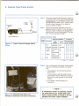
II. Resume Type Cruise Control
1
1 — BLACK
2 — BLUE
3 — BROWN
2
Step 6
Check the resume solenoid valve by applying
12-volts dc to the “ h o t” side of the valve ob
serving polarity. The energized solenoid coil
should em it an audible “ c lic k ” and the valve
should conduct vacuum. If no defect is
found, proceed to Step 7.
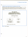
Step 7
Check the electrical operation of the en
gagement switch (figure 2-7).Use the Switch
Function Table or replace the engagement
switch with a known good switch. If no de
fect is found proceed to Step 8.
3
W
ENGAGE/COAST
BUTTON
OFF/ON/RESUME SWITCH
Switch Function Table
Test
Order Function
Figure 2-7, Typical Resume Engage Switch
Wiring.
1
Off
Resume
Cruise
Coast
2
Coast
3
Set
Switch Condition
End
Button
Released
Released
Released
Half
Depressed
Fully
Depressed
Releasing
Slider
Terminal
Connections
3-2 1-3
Off
Resume
On
On
0
C
0
c
c
c
0
0
0
0
0
On
0
0
c
On
c
c
c
O = Open
Step 8
2-1
0
C = C ontin uity
Use an Ohmmeter and check the resistance
wire and transducer solenoid coil (figure
2 - 8 ).
• The resistance wire should be between
20-25 Ohms.
• The transducer solenoid should be ap
proxim ately 6 Ohms. Make sure the trans
ducer has a good ground to the vehicle
chassis.
• If no defect is found, replace the
transducer.
— NOTE —
Figure 2-8, Check Resistor Wire and
Transducer Solenoid Coil with an Ohmmeter.
If transducer repair is required, it must
be perform ed by an authorized tran s
ducer repair facility as listed in the a p
plicable A C-Delco repair bulletins.
< 3 ^
Zc>
II. Resume Type Cruise Control
II.
Resume Type Cruise Control
NOTES
- .
<-£' c^l& U jL^yL S
r ^ f" a
. W ■£' .
( J J . O ^ T~.
‘'
/
A ^A ^'/^r . 1
1'
y
/
^
5>
/
sZ-<!& *
/
a t / 7M j >
S
p s r r lJ
cJ^
—T ~
7
5<^.
1 /</•/
1 ' '
* ^ > —
*^ ~
"
"
'
t * '"
£- /V<£/?<£
...
—-
. /\
ViA0
/-fo^r>
« ------------
T/P/4-AS 5
System with Resume, Electro-
K£5cyM £
fiESc'.wE o p d /tfirio u :
^ fcr____
ll
T5DO Q
yt&&CC47Ci? A *yf.
cXju
Ano
e x .d lt- A ^ > y ^
K /^/
'
Uut^is ^
~b>
V fl ^
c u /h P.
2-5
2-6
Resume Type Cruise Control
II. Resume Type Cruise Control
NOTES
( i*
^r~2tfW<7
t c
^
(jn ^
uL>-a-^<? >
— .-
__ <• • J C t l ___ ^ 3 ^ C
yz^& J?
/
}
J
2-8
I y £ s frt
gmly
III. Aspirator Assisted
Vacuum System (“J ” Car)
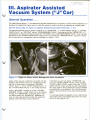
General Operation . . .
The 1982 General Motors “ J ” cars feature an aspirator assisted vacuum system for cruise control operation. It is
designed to supplement engine vacuum when the engine is under load such as traveling up a steep grade.
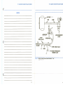
Open the fold-out page 3-4, figure 3-3, Aspirator Assisted Vacuum System Schematic, “J ” Car.
The aspirator assisted vacuum system consists of an “ ASPIRATOR” , a “ 3-PORT CHECK VALVE” , a “ 2-PORT
CHECK VALVE” , an “ AIR PUMP” and an “ AIR MANAGEMENT VALVE” . Note that air for the “ ASPIRATOR” is “ T ”
connected to the same air line that connects the “ AIR PUMP” to the “ AIR MANAGEMENT VALVE” . Also note that
the bottom of the “ 3-PORT CHECK VALVE” leads to the cruise transducer “ RESUME VALVE” . Figure 3-1 shows
an air pump and air management valve as installed in a typical “ J ” car.
Figure 3-1, Typical Air Pump, and Air Management Valve Installation.
Under normal vacuum conditions, air bleeds into the
system in the direction shown by a single arrow (fig
ure 3-3). It flows from the transducer “ RESUME
VALVE” to the “ T ” of the “ 3-PORT CHECK VALVE” , to
the “ 2-PORT CHECK VALVE” to the intake manifold.
As the “ AIR PUMP” supplies air to the “ AIR MAN
AGEMENT VALVE” , a small amount of air is diverted
through the “ ASPIRATOR” to the atmosphere. Ven
turi action w ithin the “ ASPIRATOR” develops vac
uum. It is this vacuum that provides the assistance
needed under high load cruise conditions.
If manifold vacuum falls below “ ASPIRATOR” vac
uum, the “ 2-PORT CHECK VALVE” closes and the
“ 3-PORT CHECK VALVE” opens. When the “ 3-PORT
CHECK VALVE” opens a higher vacuum is available to
the cruise system. This provides the vacuum needed
to maintain the cruise function. The “ Double A rrow s”
(figure 3-3) show direction of air flow during aspirator
assist.
To eliminate possible installation errors, note that the
check valves are arrow shaped and point in the direc
tion of air flow (figure 3-3).
III. Aspirator Assisted Vacuum System
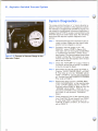
System Diagnostics . . .
The cruise control function in “ J ” cars is directly re
lated to the proper operation of the aspirator system.
For example, a plugged hose at POINT C (figure 3-3)
can cause the cruise system to become inoperative; a
plugged hose at POINT A causes cruise problems only
when the engine is under heavy load. The follow ing
steps describe aspirator system diagnostics and
service:
Step 1
Insure that all hoses and connections are se
curely in-place. Make sure the check valve
position (arrow shaped) is correct.
Step 2
Connect a vacuum gauge to the “ AS
PIRATOR” output, POINT A (figure 3-2).
Then start and run the engine at 2500 RPM,
in a closed loop operation. (Check with a
dwell meter). The vacuum gauge should read
at least 5-inches Hg. If the vacuum is lower,
remove and clean the aspirator with mineral
spirits and re-check.
Step 3
Check the “ AIR PUMP” fo r output. If there is
no output, service the air pump. If no defect
is found, proceed to Step 4.
Step 4
Disconnect the vacuum gauge at POINT A.
Plug the “ 2-PORT CHECK VALVE” at POINT
B. Then blow air into the “ RESUME VALVE
HOSE” at POINT C. Do not use compressed
air. A proper free-flow condition is indicated
if air exits at POINT A.
Step 5
Remove the plug from the “ ENGINE MAN
IFOLD VACUUM HOSE” at the manifold side
of the “ 2-PORT CHECK VALVE” , POINT B.
Plug the hose at POINT A. Blow air into the
“ RESUME VALVE HOSE” , POINT C. Air
should exit at POINT B. This completes a sys
tem check in one direction. Proceed to
Step 6.
Step 6
Check system air flow in the opposite direc
tion. Plug POINT B and blow air in at POINT
A. Then plug POINT A and blow air in at
POINT B. In either condition, air should not
exit at POINT C.
F ig u re 3-2, Connect a Vacuum Gauge to the
Aspirator Output.
3-2
III. Aspirator Assisted Vacuum System
III. Aspirator Assisted Vacuum System
NOTES
Figure 3-3, Aspirator Assisted Vacuum System Schematic, “J ” car.
L O & n x?
5
uP
3-4
Aspirator Assisted Vacuum Syste
III. Aspirator Assisted Vacuum System
NOTES
:
3-6
CdA*. U U >/ £ ^ J
SUrC^C .
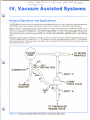
IV. Vacuum Assisted Systems
\
General Operation and Applications . . .
The 19 8 1 fk iic k LeSabre, Buick Electra and Oldsmobile 88 and 98 with a 4.1 liter V6 engine, 4-speed transm ission
a n c ra ^T ite r engine with 4-speed transm ission require vacuum assist for heavy load cruise operation.
Refer to figure 4-1. During the normal vacuum conditions of light to moderate load, air flows from PORT “ A ” to
PORT “ C” to the “ INTAKE MANIFOLD” . The single arrows in figure 4-1 show this air flow. A small amount of air
also flows from PORT “ A ” to PORT “ B ” through the “ CONNECTOR” and to the “ VACUUM PUMP” . The .035-inch
restriction in the hose connector between PORT “ B ” and the “ VACUUM PUMP” keeps the volume of air relatively
small.
Whenever manifold vacuum at PORT “ C ” drops to a level lower than the vacuum at PORT “ B ” (pump output), the
“ 3-PORT CHECK VALVE” closes PORT “ C ” . The change in vacuum level and closing of PORT “ C ” is caused by
heavy load operation. Under heavy load, the system w ill now operate off the vacuum pump. Air flow is shown by
the double arrows in figure 4-1.
r
Figure 4 -1 , Vacuum Assisted System for Heavy Load Cruise Operation.
4-1
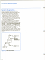
IV. Vacuum Assisted Systems
System Diagnostics . . .
The vacuum assisted system does not require
periodic maintenance. However, the follow ing diag
nostic and service procedures are applicable:
• If the 3-port check valve is blocked closed or
blocked open, the system w ill cruise below en
gagement speed or system surging w ill occur.
• If the 3-port check valve is incorrectly connected,
the cruise system w ill either be inoperative or will
cruise below engagement speed.
To correct cruise engagement or cruise operation
below engagement speed complaints, clean the
check valve and connections with mineral spirits. (See
figure 4-2) . . . Recheck by blowing low pressure air
into PORT “ A ” while PORT “ B ” is plugged and then
into PORT “ B” while PORT “ A ” is plugged. In both
cases, air should exit out of PORT “ C” . To check flow
in the other direction blow air into PORT “ C” . . . no
air should exit out of PORT “ B ” or PORT “ A ” .
Check the 3-port valve fo r proper installation. Notice
that the arrowhead shaped portion of the 3-port check
valve must always point to the intake manifold (fig
ure 4-2).
Figure 4-2, 3-Port Check Valve.
1
4-2
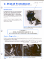
V. Diesel Transducer,
£ / f t o C t > £ ///£
rfA O
f /lZ fiT « A L
T C f i* '* * *
r to ftijo n r f lc .
Identification . . .
AC diesel transducers for cruise control produced be
fore 1980 1/2 are the non-resume type. Transducers
produced for later models are the resume type.
The diesel transducer is sim ilar in physical appear
ance to the gasoline transducer. To identify the units,
the transducer clutch housing assembly of the diesel
transducer is either “ blue” or “ black” in color
(figure 5-1).
Another difference is the electrical blade terminal ar
rangement. Starting in 1979, the “ HOLD” and “ EN
GAGE” blade term inals were changed from a “ T ” de
sign to a parallel design.
Figure 5 -1 , Diesel Transducers have a Blue or
Black Colored Housing.
— CAUTION —
DIESEL TRANSDUCERS ARE NOT TO BE
INTERCHANGED WITH GASOLINE TYPE TRANSDUCERS.
System Diagnostics . . .
The electrical and pneumatic circuits of diesel and gasoline transducers are similar. The diagnostic and service
techniques presented in Part I and Part II should be followed. However, there are some special considerations in
servicing diesel cruise control systems:
1. The diesel vacuum source is an engine driven vacutfmipu-mp (figure 5-2aK controlled by a vacuum regulator
(figure 5-2b). Regulated vacuum output is a con'stant(b to 7-inches Hg.
i/ s?<:
T~c> c% cs/S /£
Figure 5 -2 a, Typical V-8 Diesel System Vacuum
Pump.
Figure 5-2b, Vacuum Regulator.
5-1
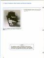
V. Diesel Transducer, Non-resume and Resume Systems
2. All diesel transducers have an orifice cup in PORT
“ A ” of the transducer clutch housing assembly
(figure 5-3).
Figure 5-3, Orifice Cup in Diesel Transducer at
PORT “A” .
— NOTE —
If transducer repair is required, it must be per
form ed by an authorized transducer repair facility
as listed in the applicable AC-Delco repair bulletins.
/ <? 7 ?
-a^ SL
/f/y C J f t ( S
t)F £ T ~tOU
C f4 P -
C H L -'i
0 f> p z"g $
VI. Electronic Cruise Control
\
C L -L ^'r^ cA
^s^JLc? ^ jbsrrn <Z.
£<td?-
^ { cJ uua
Cy<3
Non-D.F.I. (Digital Fuel Injection) and
Computer Integrated D.F.I., Cadillac
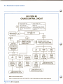
General Description
Figure 6-1 illustrates Electronic Cruise Control system components. Cruise Control is a speed control system that
uses m anifold vacuum or vacuum from a vacuum pump to actuate the throttle power unit, or servo. The servo unit
moves the throttle when its diaphragm is subjected to varying amounts of vacuum. The amount of vacuum to the
servo unit is controlled by a solenoid valve which constantly modulates vacuum to the servo unit in response to
commands from the electronic controller or fuel ECM. The controller receives signals from the engagement and
instrum ent panel switches, electric brake release switch and speed sensor. The speed sensor is located on the
back of the speedometer cluster and provides signals representative of car speed to the control system. A wire
harness connects the speed sensor to the electronic controller.
Input signals received from the sensor by the controller or ECM are used to control the servo unit solenoid valve
which regulates the amount of vacuum to the servo unit to control the speed of the car.
A two or three position (off, on-auto or cruise) switch, located on the instrum ent panel, and an engagement
switch, located at the end of the turn signal lever, control the operation of the system.
Two systems for brake release are provided:
1. An electric switch mounted on the brake pedal support cancels the controller signal by shutting off the system
and venting the servo unit to atmosphere through the servo unit solenoid valve.
2. A vacuum release valve also is mounted on the brake pedal bracket and vents the servo diaphragm to
atmosphere as a second disengagement system.
TURN SIGNAL LEVER
ENGAGEMENT SWITCH
VACUUM
CONTROL VALVE
SERVO (POWER) UNIT
& VACUUM
SOLENOID VALVE
Figure 6-1, AC Electronic Cruise Control Components.
VI. Electronic Cruise Control
Component Operation
Electronic Controller
D.F.I. (Digital Fuel Injection) Only
Cruise Control operation is one of the many functions which the ECM controls. The ECM receives input signals
from the Cruise Control engagement switches, the instrum ent panel switch, the brake release switch, the drive
switch, and the speed sensor.
The ECM processes these Cruise Control inputs together with the DFI engine control inform ation, and transm its
command signals to the vacuum control solenoid valve to provide vacuum to the system and servo unit solenoid
valve to control vehicle speed.
Non-D.F.I.
The electronic control module receives signals from the cruise engagement switch, instrum ent panel switch,
electric brake release switch and speed sensor. It processes this inform ation and transm its command signals to
the vacuum control valve to provide vacuum to the system and servo unit solenoid valve to control vehicle speed.
Speed Sensor Circuit
D.F.I. Only
The speed sensor consists of a light em itting diode
and a photo transistor enclosed in one connector
which attaches to the back of the speedometer cluster
adjacent to the speedometer cable (figure 6-2). The
photo transistor generates an electrical signal corre
sponding to vehicle speed when it is exposed to re
flected light from the light em itting diode. The photo
transistor is activated by reflected light from each
passing bar of the rotating speedometer drive mag
net. The surface of the drive magnet is highly reflec
tive to enhance the reflection of light to the photo
transistor, and the surface of the speed cup has a dull
finish which inhibits erroneous reflections. The light
from the light em itting diode is not visible to the
human eye because it is part of the infrared spectrum
of light.
Amplifier, D.F.I.
The speed sensor produces a weak voltage signal and
must be used for several speed inputs. Therefore, the
buffer am plifier is placed between the speed sensor
and the ECM to am plify and distribute the speed sig
nal. The buffer am plifier also inverts this speed signal
so the signal w ill be in a format which is understood
by the ECM.
On DFI, the speed sensor is on all cars for ECM usage;
cruise control uses buffer am plifier output.
VI. Electronic Cruise Control
Non-D.F.I.
On V-6 equipped cars with CCC, the speed sensor
circu it is sim ilar to DFI, except the speed signal is sent
to an electronic controller, or control module, for
cruise control purposes (figure 6-3). On diesel
equipped cars with digital speedometer clusters, the
cruise control circu it is the same as used on V-6;
however, diesel equipped cars with mechanical
speedometer clusters do not use a buffer am plifier in
their speed sensor circuit.
Vacuum Control Valve
The vacuum control valve (figure 6-4) opens when the
system is engaged and the green light on the instru
ment panel switch is illum inated. The valve operates
in response to a signal from the ECM or the electronic
controller. When the vacuum control valve is open,
vacuum is available at the servo unit solenoid valve for
control of the servo unit as described below. The vac
uum control valve is closed when the system is off.
SPEEDO FRAME
POWER UNIT
VACUUM
T ° VACUUM
Servo Unit Solenoid Valve
The solenoid valve constantly modulates vacuum to
the servo unit in response to commands from the
electronic controller or ECM so that the throttle is in
the proper position for the desired cruise speed (fig
ure 6-4).
Servo Unit
The Servo Unit (figure 6-4) is a vacuum actuated vari
able position diaphragm assembly that positions the
throttle when the system is in operation. It operates
the throttle linkage via a bead chain actuator (4.1 liter
V-6 “ C” car), com bination chain and cable actuator
(4.1 liter V-8 “ C” car) or rod actuator (all other mod
els). When controlled vacuum is applied to evacuate
the servo, atm ospheric pressure applies a force to the
diaphragm and moves the diaphragm inward, pulling
on the actuator to open the throttle.
Figure 6-4, Vacuum Control Valve and Servo
(Power) Unit.
VI. Electronic Cruise Control
Brake Release Switches
One electrical brake release switch and one vacuum release valve are employed in the Cruise Control system
(figures 6-5A and 6-5B).
When the brake pedal is depressed, the electric release switch cuts off the voltage supplied through the instru
ment panel switch to the electronic controller. Engagement switch operation is required to return the electronic
controller to operation. The vacuum release valve operates after the electric release switch disengages whenever
the brake pedal is depressed. This switch serves as a backup release system and opens a port that vents the servo
unit to atm ospheric pressure, thereby allowing the throttle to return to the idle position.
BRAKE PEDAL MOUNTING BRACKET
BRAKE PEDAL
BRACKET
SPEEDOMETER
SHAFT
VACUUM RELEASE
VALVE AND TORQUE
CONVERTER CLUTCH
RELEASE SWITCH
BRAKE PEDAL
STOP LAMPS AND
CRUISE CONTROL
RELEASE SWITCH
VALVE ASSEMBLY ADJUSTMENT PROCEDURE
1. INSERT VALVE ASSEMBLY INTO TUBULAR
CLIP UNTIL VALVE BODY SEATS ON TUBULAR
CLIP.
2. PULL BRAKE PEDAL REARWARD AGAINST
INTERNAL PEDAL STOP. VALVE ASSEMBLY
WILL BE MOVED IN TUBULAR CLIP PROVIDING
PROPER ADJUSTMENT.
Figure 6-5A, Cruise Control Brake Valve and
Release Switch, E and K.
STOP LAMPS AND
CRUISE CONTROL
RELEASE SWITCH
VACUUM RELEASE VALVE AND
TORQUE CONVERTER CLUTCH
RELEASE SWITCH
Figure 6-5B, Cruise Control Brake Valve and
Release Switch Except E and K.
VI. Electronic Cruise Control
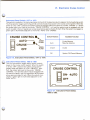
Instrument Panel Switch, 1977 to 1979
This switch is located on the instrument panel to the left of the steering column adjacent to the headlamp switch.
The three position toggle switch (figure 6-6) controls the electrical power to the cruise control system. When the
switch is in the “ OFF” position the system cannot be engaged. When the switch is in either “ CRUISE” or “ AUTO” ,
the amber light to the right of the words “ CRUISE CONTROL” is lit and the system may be engaged with the
switch located in the turn signal lever at any speed above approximately 25 mph. When the system is engaged, a
green light is illum inated adjacent to the words “ AUTO” and “ CRUISE” .
CRUISE CONTROL
AUTO
CRUISE
*
OFF
Switch Position
AMBER
FILTER
GREEN
FILTER
Available Function
Auto
Cruise Memory
Resume Advance
Cruise
Cruise
Off
System Off/Cancel Memory
Figure 6-6, Instrument Panel Switch, 1977 to 1979.
Instrument Panel Switch, 1980 to 1983
This is a tw o-position toggle switch which controls
power to the cruise control system. When the switch
is in the “ OFF” position the system cannot be en
gaged. When the switch is in the “ ON-AUTO” posi
tion, the amber light next to the words “ CRUISE
CONTROL” is lit and the system may be engaged with
the switch located in the turn signal lever at any speed
above approxim ately 25 mph. When the system is en
gaged, a green light is illum inated adjacent to the
word “ AUTO” .
CRUISE CONTROL
ON- -AUTO
OFF
Figure 6-7, Instrument Panel Switch,
1980 to 1983.
VI. Electronic Cruise Control
Cruise Engagement Switch, 1979-1980
The engagement switch, located within the turn signal lever, has various modes of operation and is dependent
upon the position of the instrum ent panel switch (figure 6-8).
With the instrum ent panel switch in the “ OFF” position, the system w ill not operate. With the instrum ent panel
switch in the “ CRUISE” position, the engagement switch operates as follows:
a. Switch in Fully Released Position:
1. System not engaged: No function of the system w ill occur.
2. System has been previously engaged: Control voltage is being supplied to the servo unit solenoid valve from
the electronic controller. The unit solenoid valve regulates vacuum to the servo unit which maintains throttle
position for desired speed.
b. Switch Partially Depressed (Detent Position)
The electronic controller is activated and a control voltage is supplied to the servo unit solenoid valve. In turn, the
servo unit solenoid valve regulates the vacuum supplied to the servo to initially set or reset the speed.
c. Fully Depressed
The electronic controller signals the power unit solenoid valve to vent the servo unit to atmosphere. This position
is used by the driver when a decrease in speed is desired.
The driver may fully press the button with no pressure on the accelerator pedal. In this case, the throttle returns to
idle and the car slows. When the button is released, the vehicle w ill cruise at the new lower speed.
With the instrument p an el switch in the “AUTO” position, the engagem ent switch operates as follows:
a. Switch in Fully Released Position
Operation is the same as when the instrument panel switch is in the “ CRUISE” position.
b. Switch Partially Depressed (Detent Position)
This position allows the driver to engage the system at
a given speed, resume that speed after braking and
accelerate from a previously set speed. After obtain
ing the desired speed using the accelerator pedal the
driver can partially depress the engagement switch
and the electronic controller w ill provide a control vol
tage to the servo unit solenoid valve and regulate the
required vacuum to the servo unit to maintain the set
speed. If the driver momentarily applies the brakes
and wishes to resume the previously set speed, par
tially depressing and releasing the engagement
switch (above approx. 25 mph), will accelerate the car
at a controlled rate until the previously set speed is
reached. If the driver wishes to advance the speed of
the car from an initial set speed, partially depressing
and holding the engagement switch w ill accelerate
the car at a controlled rate until the push button is
released. The car w ill now cruise at the new speed.
Figure 6-8, Cruise Engagement Switch,
1979-1980.
c. Fully Depressed
Operation is the same as when the instrum ent panel
switch is in the “ CRUISE” position.
VI. Electronic Cruise Control
Cruise Engagement Switch, 1980 and Later
The engagement switch, located within the turn signal
lever, has various modes of operation (figure 6-9).
With the instrum ent panel switch in the "O FF” posi
tion, the system w ill not operate. With the instrument
panel switch in the “ ON-AUTO” position, the en
gagement switch operates as follows:
a. Switches in Fully Released Position:
1. System not engaged: No function of the system will
occur.
2. System has been previously engaged: Control vol
tage is being supplied to the servo unit solenoid valve
from the electronic controller. The servo unit solenoid
valve regulates vacuum to the servo unit which main
tains throttle position for desired speed.
Figure 6-9, Cruise Engagement Switch,
1980 and Later.
b. Pushbutton Depressed and Held
After obtaining the desired speed by using the ac
celerator pedal, the driver can momentarily depress
the pushbutton switch and the electronic controller
w ill provide a control voltage to the servo unit so
lenoid valve and regulate the required vacuum to
maintain the set speed. When a decrease in speed is
desired, the driver may depress and hold the button
with no pressure on the accelerator pedal. The elec
tronic controller signals the servo unit solenoid valve
to vent the servo unit to atmosphere. In this case, the
throttle returns to idle and the car slows. When the
button is released, the vehicle w ill cruise at the new
lower speed.
c. Slide Lever Actuation
This switch allows the driver to resume a previously
set cruise speed after braking and accelerate from a
previously set speed. If the driver momentarily applies
the brakes and wishes to resume the previously set
speed, depressing and releasing the slide switch
(above approx. 25 mph), w ill accelerate the car at a
controlled rate until the previously set speed is
reached. If the driver wishes to advance the speed of
the car from an initial set speed, actuating and hold
ing the slide switch w ill accelerate the car at a con
trolled rate until the slide switch is released. The car
will now cruise at the new speed.
6-7
VI. Electronic Cruise Control
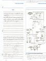
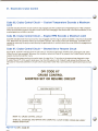
Typical Circuit Operation,
Non-D.F.I.
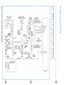
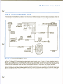
R efer to the Non-DFI schematic diagram on the
fold-out page, figure 6-10.
With the IGNITION SWITCH in “ Run,” voltage is
applied through the C/C FUSE to the CRUISE CON
TROL SWITCH. With the control switch in “ AutoCruise,” current flows through the amber CRUISE-ON
INDICATOR to ground. Voltage is now available
through terminal D on the control switch and the
BRAKE SWITCH and applied: 1) through the green
CRUISE ENGAGE INDICATOR to terminal B of the
CRUISE CONTROLLER; 2) to terminal H of the
CRUISE CONTROLLER; and 3) through the ENGAGE
SWITCH ASSEMBLY to terminal E or D of the CRUISE
CONTROLLER.
The CRUISE SERVO SOLENOID controls the amount
of vacuum applied to the CRUISE SERVO. This sole
noid has no effect on the CRUISE SERVO, however,
until the CRUISE VACUUM SOLENOID is open. The
CRUISE VACUUM SOLENOID is open to let vacuum
pass through only when the system is engaged.
The VEHICLE SPEED SENSOR sends a variable signal
to the CRUISE CONTROLLER based on car speed.
When car speed is over about 25 mph, the CRUISE
CONTROL system can be engaged.
With the CRUISE CONTROL SWITCH in “ AutoCruise,” the system is engaged by briefly pressing the
“ Set/Coast” lock-in button. The CRUISE CONTROL
LER then lets current flow through terminal C and the
CRUISE VACUUM SOLENOID to ground. This opens
the CRUISE VACUUM SOLENOID, and vacuum is
supplied to the CRUISE SERVO SOLENOID. The
CRUISE SERVO SOLENOID is operated by current
through CRUISE CONTROLLER terminal F. Signals
from the VEHICLE SPEED SENSOR vary that current
when car speed changes. These variations in current
change the amount of vacuum the CRUISE SERVO
SOLENOID applies to the CRUISE SERVO. The
CRUISE SERVO keeps the set speed. The CRUISE
CONTROLLER also applies ground to the green
CRUISE-ENGAGE INDICATOR through terminal B.
The indicator goes on.
Once the speed has been set, depressing the gas
pedal w ill increase car speed. Releasing the gas pedal
lets the car coast back down to the set speed. The
Cruise Control set speed is not changed by speeding
up unless the “ Set/Coast” lock-in button is pressed.
Set speed can be reduced by pressing and holding the
“ Set/Coast” button. This breaks the circuit through
controller terminal C. The CRUISE VACUUM SOLE
NOID closes, and the CRUISE SERVO no longer gets
any vacuum. The car coasts to a lower speed. This
speed becomes the new set speed when the button is
released.
If the “ Resume/Accel” slide switch is moved and held,
the car w ill speed up. When it is released, a new set
speed is established. If, after braking, the slide switch
is moved and released, the car w ill resume the previ
ously set speed (memory speed).
The BRAKE SWITCH w ill disengage the set speed but
not the memory speed setting. You must turn off the
control switch or the IGNITION SWITCH, or set
another cruise speed using the “ Resume/Accel” slide
switch to erase the memory speed setting.
VI. Electronic Cruise Control
VI. Electronic Cruise Control
HOT IN RUN
r - — ----------------
!
J
i
L_
■T FUSE
BRAKE SWITCH
OPEN WITH
BRAKE PEDAL
DEPRESSED
-> C/C
FUSE
r
3 AMP
j m
5 YEL
n i___
904
L6;
t
.5 YEL
.5 PNK/BLK
C l 03
904
919
B£
.5 PNK/BLK I 919
C223
DK GRN I 919
ENGAGE
SWITCH
ASSEMBLY
RESUM E/ACCEL
(
I
SET/COAST
>
K
A
y
mmmmJ
*
YEL
*
a
916
RED
917
C223
:
CRUISE C O NTR O L ENGAGE
*
5 YEL
916 .5 RED
SW ITCH ASSEM BLY HARNESS
917
CO NNECTO R V IE W
C226
X
PO W ER
GROUND
B
C
CRUISE
SO LENOID
ENABLE
OUTPUT
5 DK BLU
.5 BLK
D
995
.5 BLK
FROM S321,
POWER
DISTRIBUTION,
PAGES 62, 66
(VEHICLE
SENSORS)
INPUT
S E T / C O A S T IN P U T
SERVO OUTPUT
F
w
T
5 LT BLU
403
A
C226
402
C290
OPERATED
BY BRAKE
PEDAL
T
i
VACUUM
RELEASE
VALVE
35 LT GRN
403
BLK
CRUISE
CONTROLLER
E
C
C225
COMPUTER
COMMAND
CONTROL-V6 ► ----
RESUM E/ACCEL
T
931
VENTS
.5 DK BLU/WHT k 403
F
C RUISE SER V O
C290
WIT H B R A K E
RED
PEDAL
DEPRESSED
j SPEED
151
.5 BLK
’ I BUFFER
AMPLIFIER
j
SIGN A L
| OUTPUT 2
SOLID STATE
SEE GROUND
DISTRIBUTION
Y
' |G R O U N D
+ S471
E IS P E E D SIGN AL
^INPUT
.3 BLK |
151
.5
BLK
I
|
S222
3 BLK I 151
■
A nni
it g r n
151
T
REFEREN „
sss
G
LT
GRN
8 VOLT
blk
J
! ° .5 PNK/BLK
POW ErJ)
39
____________
962
931
C711
BLK
■
\
LT GRN
G.
LT GRN
“
SO LID S T A T E
"
I VhHIULh
SPEED
TO THROTTLE
LINKAGE
995
F4
BLK
S O LID S T A T E
_______________________________________ 1 SFNSOR
_E.
RED
VEHICLE /
SPEED
SENSOR
SEE GROUND
DISTRIBUTION
G113
G249
SEE COMPUTER
COMMAND CONTROL V6
(CHECK ENGINE
LIGHT)
Figure 6-10, Non-D.F.I. Cruise Schematic Diagram.
6-9
6-10
VI. Electronic Cruise Control
VI. Electronic Cruise Control
HOT IN RUN
1
FUSE
BLOCK
.5 YEL
z
CRUISE CONTROL ENGAGE
SW ITC H A S S E M B L Y H A R N E S S
CONNECTOR VIEW
AUTO
LT BLU/
BLK
CRUISE “ ON'
INDICATOR
903
ENGAGE
SWITCH
ASSEMBLY
B
RESUME/
ACCEL
SET/
*
COAST
M
A
ELECTRONIC
FUEL INJECTION
(DRIVE/ADL SWITCH)
cN
SEE GROUND
DISTRIBUTION
YEL
916
RED
.5 YEL
917
J C223
916
917
.5 RED
.8 BLK/ U 243
WHT
ELECTRONIC
CONTROL MODULE
C714
8
E
B R A K E INPUT
D
CRUISE CONTROL
SOLID STATE
CRUISE ENGAGE
P O W ER U N IT
OUTPUT
7
SO LENOID V A L V E OUTPUT
ENABLE
S ET/CO A ST INPUT
INPUT
8 VOLT
SPEED SEN SE INPUT
10
2
.35 LT GRN
RED
RED
i
1
1
.5 DK BLU/WHT
403
SO LID
BLK
STATE
LT GRN
BLK
i
1
1
1
.8 BLK
C638
Figure 6-11, D.F.I. Cruise Schematic Diagram.
6-11
6-12
S O L ID
STATE
LT GRN
DRIVE
5 VOLT
INPUT
RETURNS
REF
20
VEHICLE
SPEED SENSOR
.5 LT GRN
J
C
RESUM E/ACCEL
5
1
VI. Electronic Cruise Control
Typical Circuit Operation,
D.F.I.
VALVE SOLENOID and CRUISE ENGAGE INDICATOR.
The ECM w ill operate the CRUISE SERVO SOLENOID
VALVE with the Power Unit Solenoid Valve input sig
nal to maintain the selected speed.
R efer to the D.F.I. cruise schematic diagram on the
fold-out page, figure 6-11.
Once the speed has been set, depressing the gas
pedal will increase car speed. Releasing the gas pedal
lets the car coast back down to the set speed. The
Cruise Control set-speed does not change by speed
ing up unless the Set/Coast button is depressed. If the
driver depresses the Set/Coast button and releases
the gas pedal at the same time, then the throttle re
turns to an idle position and the car’s speed de
creases. The car w ill cruise at the speed of the car
when the button is released.
With the IGNITION SWITCH in “ Run,” voltage is
applied through the C/C FUSE to the CRUISE CON
TROL SWITCH and the CRUISE CONTROL RELEASE
SWITCH. With the control switch in “ On-Auto” cur
rent flows through the amber indicator bulb to
ground. Current also flows through terminal D on the
control switch and follow s 2 paths: 1) to the ELEC
TRONIC CONTROL MODULE (ECM) as the Cruise
Control Enable signal and 2) to the ENGAGE SWITCH
ASSEMBLY.
Current flow from the CRUISE CONTROL RELEASE
SWITCH follows 2 paths: 1) to the ECM as the Brake
Input signal and 2) to the VACUUM CONTROL VALVE
SOLENOID.
The VEHICLE SPEED SENSOR sends low voltage sig
nal pulses w hich represents car speed to the BUFFER
AMPLIFIER. The A m plifier modifies the pulses to put
them in the right form for the ECM. One of the ECM
Functions is to combine the Cruise Control input sig
nals and the DIGITAL FUEL INJECTION (DFI) engine
control inform ation. It then sends command signals to
the VACUUM CONTROL VALVE SOLENOID and
POWER UNIT SOLENOID VALVE.
The CRUISE SERVO SOLENOID VALVE controls the
amount of vacuum applied to the CRUISE SERVO.
This has no effect on the CRUISE SERVO, however,
until the VACUUM CONTROL VALVE is open. The
VACUUM CONTROL VALVE is open (to let vacuum
pass through to the power unit) only when the system
is engaged.
When the control switch is in “ Auto-O n” and the vehi
cle speed is above 25 mph, the system can be en
gaged by depressing the Set/Coast button in the En
gage Switch Assembly. Current w ill flow through the
switch to the ECM as the Set/Coast Input signal.
When the button is released the ECM sends a Cruise
Engage signal to operate the VACUUM CONTROL
The system can be disengaged four ways: 1) by De
pressing the brake pedal (this opens the CRUISE
CONTROL RELEASE SWITCH by removing the Brake
Input signal to the ECM and vents the POWER UNIT
vacuum to the atmosphere); 2) by Moving the shift
lever out of the Drive range (this removes the Drive
Input from the ECM); 3) by turning the CRUISE CON
TROL SWITCH to “ o ff” ; 4) when the ECM sets any
diagnostic code.
Turning the system “ o ff” erases the speed in memory.
To again use the system it must be turned back “ o n ”
and repeat the procedures for setting a desired speed.
If the system has been disengaged by any method
(other than turning the system “ o ff” ), the system w ill
resume operation when the cause of disengagement
has been removed. To re-engage the system place the
ENGAGE SWITCH in the “ Resum e/Acceleration” po
sition and release it. The ECM receives the Resume/
Accel input signal and operates the CRUISE SERVO
SOLENOID VALVE to accelerate the vehicle at a con
trolled rate until the previous set-speed is reached
again. If the driver wishes to advance the speed from
the initial set-speed keeping the switch depressed will
accelerate the car at a controlled rate until the switch
is released. The car w ill not cruise at the new speed.
6-13
VI. Electronic Cruise Control
Diagnosis, Non-D.F.I.
Road Test
Step 1
Put dash switch in “ OFF” position. Drive car
to 50 mph. Push engagement switch button
on turn signal lever and release. System
should remain inoperative.
Step 2
Put dash switch in CRUISE (center) position
on 1977-79 models. Amber light should
come on. On 1980 and later models put dash
switch in “ ON-AUTO” position and Amber
light should come on.
Step 8
Push engagement switch button all the way
in and hold. Green light should go out. Coast
to 50 mph.
Step 9
Release button to engage system at 50 mph;
green light should come on and vehicle
should maintain that speed.
Preliminary Inspection
M ake sure all test equipm ent such as test lights and
voltmeters are in good working order prior to using
them.
a. Electrical and Vacuum Inspection Fuse
Engage system by momentarily pushing the
turn signal engagement switch button and
releasing at 50 mph; remove foot from ac
celerator. Green light should come on when
button is released and system is engaged.
Vehicle should maintain speed of 50 mph.
Note amount, if any, by which car speed d if
fers from the 50 mph speed when engaged.
This is called “ lo ck-in ” error and can be cor
rected by the adjustment procedure.
Inspect Cruise Control fuse and replace as necessary.
Step 4
Put dash switch in “ AUTO” position on a
1977 thru 1979 model. The vehicle speed
should not change.
Step 5
Push engagement switch button in to the de
tent position and hold on a 1977 thru 1980
model, or push slide switch and hold on a
1981 or later model. Vehicle should acceler
ate at a controlled rate. Release slide or but
ton to engage system at cruise speed or ap
proximately 55 mph. System should now be
set at a new speed and vehicle should main
tain that speed.
Step 3
Step 6
Step 7
Depress brake pedal an estimated Vz inch;
green light should go out confirm ing action
of electric brake release switch and vehicle
should start to slow down. Allow vehicle to
slow to approximately 45 mph, using brakes
if desired.
Momentarily depress slide switch, on 1981
and later, or on 1977-1980 units depress en
gagement switch button to detent position,
and release. Vehicle should accelerate at a
controlled rate and resume previously set
speed of 55 mph and maintain that speed.
Green light should come on when slide or
button is released.
b. Electric Brake Release Switch (Engine Off)
On Car Check:
Step 1 Turn ignition ON and instrum ent panel
switch to “ ON-AUTO” or CRUISE position.
Step 2
Connect test light (or voltmeter) to ground.
Step 3
Probe: Feed wire at connector; lamp should
light (12 volts on meter), indicating proper
feed.
Step 4
Check switch adjustment with probe still at
Feed wire depressing brake pedal — (Vb” V2” ) should turn out light (no voltage on
meter).
Step 5
If lamp in (3) did not light, probe wire in adja
cent connector cavity. If probe lights (12
volts on meter) adjust or replace switch as
necessary. If no light or 12 volts, w iring to
switch is faulty, refer to wiring diagrams in
this section.
c. Off Car Check:
Step 1 Use ohmmeter or self-powered test light.
Step 2
With switch plunger extended, meter should
read infinity (open circuit). Test light OFF.
Step 3
With switch plunger fully depressed, meter
should indicate continuity. Test light ON.
Instrument Panel Switch 1977 to 1979
a. On Car Check-Switch (Engine Off)
Step 1 Turn ignition ON.
Step 2
Connect test light on voltmeter to ground.
Step 3
Disconnect the 3 wire connector from the
turn signal lever engage switch harness to
the cruise harness connector.
VI. Electronic Cruise Control
Step 4
Probe the three term inals of the cruise har
ness connector, first with the instrument
panel switch in “ OFF” , then “ CRUISE” , and
finally in the “ AUTO” position. In either
“ Cruise” or “ A uto ” switch positions, the
amber indicator should light. The checks
should indicate the follow ing:
Instrument Panel Switch
On Car Test, 1977 to 1979
Instrument
Panel
Switch
Position
Test Light
Indication at Terminal
No. 1
(Yellow)
No. 2
(Green)
No. 3
(Red)
Auto
Off
On
Off
Cruise
On
Off
Off
Off
Off
Off
Off
Instrument Panel Switch (Off Car) 1977
to 1979
Step 1
Refer to Service Manual for removal and in
stallation of the switches: Use ohmmeter or
self powered test light.
Step 2
Identify printed circu it terminals from letters
A thru H on harness connector. Letters read
from bottom to top A thru H on switch
assembly.
Step 3
The checks should indicate this follow ing:
Instrument Panel Switch
Off Car Test, 1977 to 1979
Instrument
Panel
Switch
Position
a. On Car Check-Switch (Engine Off) 1980 and Later
Step 1 Turn ignition ON.
Step 2
Connect test light or voltm eter to ground.
Step 3
Disconnect the 3 wire connector from the
turn signal lever engage switch harness to
the cruise harness connector.
Step 4
Probe the three term inals of the cruise har
ness connector, first with the instrum ent
panel switch in “ OFF” , then in the “ ONAUTO” position. In “ OFF” position, there
should be no power to any of the three ter
minals. In the “ O n-Auto” position — center
cavity (B), pink/black wire, test lamp should
light (12 volts on meter) and outer cavities
(A), yellow wire, and (C), red wire, should
NOT light. In the “ O n-Auto” switch position,
the amber indicator should light.
Engage Switch and Harness
(On or Off Car) 1977 to 1979
The engage switch can be checked after disconnect
ing it from the harness and perform ing the follow ing
tests with an ohmmeter:
Engage Switch On or
Off Car Test, 1970 to 1979
Indication
Between Terminals
1 to 2
(YellowGreen)
1 to 3
(YellowRed)
2 to 3
(GreenRed)
Closed
Closed
Closed
Partially
Depressed
Open
Open
Closed
Fully
Depressed
Closed
Open
Open
Engage
Switch
Released
Indication
Between Terminals
A to B
A to C
E to F
Closed
Open
Closed
Cruise
Open
Closed
Closed
Off
Open
Open
Open
Aut<
instrument Panel Switch
VI. Electronic Cruise Control
Engage Switch and Harness
(On or Off Car) 1980 and Later
Step 2
Connect a jum per wire from the positive ter
minal of the battery to one terminal of the
valve being tested.
The turn lever engage switch can be checked after
disconnecting it from the harness and perform ing the
follow ing tests with an ohmmeter.
Step 3
Connect another jum per wire to ground.
Step 4
Brush the other end of the grounded jum per
wire across the remaining terminal of the
valve. You must hear the vacuum control
valve or servo unit solenoid valve open and
close as you make and break contact with
the terminal. Both valves w ill click twice indi
cating that each respective valve is fu n ctio n
ing properly.
Engage Switch On or
Off Car Test, 1980 and Later
Indication Between Term inals
1 to 2
(YellowGreen)
1 to 3
(YellowRed)
2 to 3
(GreenRed)
Open
Open
Open
Slide
Depressed
Closed
Open
Open
Pushbutton
Depressed
Open
Open
Closed
Engage
Switch
Released
c. Functional Test (Engine O perational)
Step 1 Prior to starting the engine, disconnect the
bead chain, cable or rod actuator at the servo
unit.
Step 2
Disconnect the electrical connectors at the
vacuum control and servo unit valves.
Step 3
If incorrect indications occur, replace engagement
switch and harness.
With one lead of ohmmeter connected to steering
column m ounting bracket, check each terminal. All
should show open. If any indicate continuity, a short
exists and lever and harness must be replaced. Move
shift lever through full range when checking each
wire.
Start engine and let idle. Install jum per wires
from battery positive terminal to one terminal
on both vacuum control valve and servo unit
solenoid valve. Ground second terminal on
each valve. Servo diaphragm should fully re
tract, indicating both solenoid valves are
functional.
Step 4 Remove battery jum per from servo so le no id ;
the diaphragm should return to full exten
sion proving that no vacuum is reaching it. If
it does not fully return, the servo unit sol
enoid valve is leaking and must be replaced.
Step 5
Vacuum Control and Servo Unit
Solenoid Valves
a. Resistance Test (Engine Off)
Step 1 Disconnect electrical connector at solenoid
valve being tested.
Reinstall battery jum per wire to servo sol
enoid and remove battery jum per from vac
uum control valve. Diaphragm should return
to full extension. If it does not, the vacuum
control valve is leaking and must be
replaced.
d. C ontroller Current Leakage Test at Servo Unit
Solenoid Valve Connector (Engine O perational)
Step 1 Disconnect electrical connector at servo sol
enoid valve. I.P. switch in “ On” position.
Step 2
Connect ohmmeter to solenoid valve
terminals.
Step 3
Measure resistance, it should be between 37
and 48 ohms on servo unit valve and between
23.5 and 27.5 ohms on vacuum control valve.
Step 2
With car running at idle, check D.C. voltage
between connector terminals. Must be less
than 1.0 volt D.C.
Step 4
If reading is outside of limits replace appli
cable valve.
Step 3
Momentarily increase idle speed for several
seconds. Voltm eter must indicate less than
1.0 volt D.C.
Step 4
Any indications above 1.0 volt D.C., replace
controller.
b. Functional Test (Engine Off)
Step 1 Disconnect electrical connector at valve
being tested.
e. Instrum ent Panel Switch (Am ber “ ON” Lamp
Inoperative or M alfunctioning) (Engine Off)
Step 1 Turn ignition switch ON.
Step 2
Place instrum ent panel switch in “ ONAUTO” , or CRUISE.
VI. Electronic Cruise Control
Step 3
If amber “ ON” lamp is not illum inated, check
for burned-out lamp, open ground wire, open
connector, inoperative switch, blown fuse or
printed circuit.
Step 4
Place instrum ent panel switch in “OFF”
position.
Step 5
If amber “ ON” lamp is illum inated, check for
shorted leads or inoperative switch, or blown
fuse.
f. Instrument Panel Switch (Green “Cruise” Lamp
Circuit)
Step 1 If road test shows system controls speed and
“ green” indicator light is inoperative, check
for burned out lamp or open in wiring be
tween switch connector and controller con
nector (pink wire) and inoperative controller.
With I.P. switch in “ ON-AUTO” (ignition on),
ground cavity “ B ” in controller connector;
green lamp should light. If it does but not
during road test, replace controller.
Step 2
If green indicator remains “ o n ” when system
is not controlling speed, check for short in
harness between switch and controller con
nector (pink wire). If OK, replace controller or
ECM.
internal circuitry of the electronic controller.
If voltage is outside of lim its replace the
controller.
Step 3
Connect voltm eter between ground and No.
3 (red) term inal. Voltage should be 1 to 2
volts less than value in terminal No. 2. This is
the voltage drop through the light em itting
diode. If voltage is outside of limits, replace
the speed sensor.
Step 4
Connect voltm eter between ground and No.
1 term inal (green wire). Roll car forward
while checking voltage. Voltage should flu c
tuate at least 5 volts from low points to peaks
(output of photo transistor) and each peak
should be w ithin 1 volt of reading at No. 2
term inal (black wire — Step 2 above). Also,
two peaks should occur w ithin six feet of car
travel.
This check requires a high quality voltm eter (20,000
ohms per volt or greater).
Vacuum System Inspection
(Engine Operational)
Step 1
Prior to starting the engine, disconnect the
bead chain, cable or actuating rod at the
servo unit.
Step 2
Disconnect the electrical connectors at the
vacuum control and servo unit solenoid
valves.
There should be no attempt made to repair the elec
tronic cruise controller. Check to make sure connec
tors are fully seated — Red (8) way and red (3) way
speed sensor. If all other components have been
checked and found to be functioning properly — then
replace the controller.
Step 3
Actuate both the vacuum control and servo
unit solenoid valve with jum per wires. This is
done by connecting jum per wires from the
battery positive term inal to one term inal on
each valve and grounding the remaining
term inal on each valve with another set of
jum per wires.
Speed Sensor Check On
(Engine Off)
Step 4
Start the engine and let idle.
Step 5
With brake pedal in free position, diaphragm
should pull in to full stroke. Have a helper
depress the brake pedal down about V/2
inches and the diaphragm should relax to its
free position proving that the vacuum release
valve is w orking and its hose unobstructed.
Step 6
If system w ill not hold vacuum, remove brake
release vent valve hose at servo unit and plug
servo unit hole (m anifold vacuum should be
open).
Step 7
If servo unit draws down then problem condi
tion exists in brake release vacuum vent
system.
Step 8
If servo unit w ill not draw down, inspect dia
phragm and connectors at valves fo r leaks.
Step 3
Amber light should be on to confirm power
supply.
Controller
Step 1
Turn ignition on and Cruise dash switch to
“ ON-AUTO” position.
Step 2
Refer to Service Manual for partial removal
of the speedometer cluster for access to the
speed sensor 3-way connector located on
the electronic controller. Connect voltmeter
between ground and No. 2 (black) terminal.
Note and record this voltage reading. Should
read voltage between 9 and 11 volts. This is
less than full battery voltage because of the
Figure 6-12, D.F.I. Cruise Control Circuit Diagram.
a
CQ
■
C
T|
—
r
CD
■
CD
■
■
rv)
v>'
r-+
CRUISE CONTROL
IP . SWITCH
CRUISE CONTROL
ENGAGEMENT SWITCH
IT
SPEED
SENSOR
CD
ORN ECM
CONNECTOR P3
AMBER IND
1^
OFF
O
r-+
W
o’
CD
T|
“"t
C
03
ILLUMINATION
r r iz r
ZZZ
<■ ■5■ ■‘
CD
^
autoM
3
CD
CRUISE ENGAGE
t— ------------------------------------GREEN IND \ J h -------------------------------- “ »
961 - 2 - SPEED SENSOR
916 - D - RESUME/ACCEL.
917 - C - SET/COAST
903 - E - ENABLE
919 - 8 - BRAKE
O
:x
(D
CD
3
CRUISE CONTROL
BRAKE
SWITCH
N.C. >
CD
O
■■ ■ ■
O
o
(/>
0
CRUISE VALVE DR
fl)
CD
3
O
(/>
cS'
CRUISE CONTROL
POWER VALVE
H
□ID
rh
t
O
T
c
</>'
o
3
CD
zr
CRUISE ENGAGE
3
o'
o
CQ
TO
HEADLAMP
SWITCH
o
o
O
3
0)
r+
o'
Q.
243 - J - DRIVE
m
<o
ECM
c
-
-----------
VI. Electronic Cruise Control
Code 60, Cruise Control Circuit, Transmission Not In Drive
Code 60 (figure 6-13) indicates that the transm ission was not in drive when the Cruise Control was engaged.
Whenever the condition which set Code 60 is present, the Cruise Control w ill disengage.
To begin the diagnosis, perform the switch tests. If Code 73 sets, refer to diagnostic chart 73. If Code 73
passes, then the DFI system is OK. Code 60 was caused by operator error or by an im properly adjusted transm is
sion lever.
DFI CODE 60
CRUISE CONTROL CIRCUIT TRANSMISSION NOT IN DRIVE
REFER TO: CRUISE CONTROL CIRCUIT
Figure 6-13, D.F.I. Code 60.
VI. Electronic Cruise Control
DFI CODE 63
CRUISE CONTROL CIRCUIT
REFER TO: CRUISE CONTROL CIRCUIT
WHEN ALL DIAGNOSIS AND REPAIRS ARE COMPLETED, CLEAR STORED CODES AND VERIFY PROPER OPERATION.
Figure 6-14, D.F.I. Code 63.
6-20
VI. Electronic Cruise Control
Code 63, Cruise Control Circuit, Car
and Set Speed Tolerance Exceeded
Figure 6-14, Code 63 indicates that the Cruise Control
was engaged at a certain set speed and the vehicle
speed was more than 20 miles per hour above or
below this set speed. Whenever the condition which
set Code 63 is present, the Cruise Control w ill
disengage.
a. Code 63 may result from operator error or a system
m alfunction. To diagnose a system malfunction, pro
ceed as follows:
Step 1
Start engine and momentarily disconnect
6-pin weatherpack connector at the rear of
the fuel tank (engine w ill stall).
Step 2
Turn cruise enable on.
Step 3
Enter diagnostics and display .9.6 for output
cycling. Check the cruise control vacuum
and power valves to determine if they cycle
(click) on and off.
If the vacuum and power valves are OK, check for
binding linkage. If the linkage is not binding, check
for vacuum leaks or blockages. If there are no vacuum
problems, then the DFI system is OK.
b. If the vacuum valve does not cycle, disconnect the
vacuum valve connector and connect a test light be
tween the harness connector pins while perform ing
the output cycling tests. If there is no light, check
circuit #919 or # 40 3 for an open. If the wiring is OK,
check for a faulty ECM connector or faulty ECM.
c. If there is a steady light, check circu it #403 for a
short to ground. If the circu it is OK, check for a faulty
ECM connector or faulty ECM.
d. If the light is on for 3 seconds and off for 3 sec
onds, then the ECM and w iring harness are OK, re
place the vacuum valve solenoid.
e. If the power valve does not cycle, disconnect the
power valve connector and connect a test light be
tween the harness connector pins while perform ing
the output cycling tests. If there is no light, check
circuits #402 and # 151 for an open or circu it #402 for
a short to ground. If the circuits #402 and #151 are
OK, check fo r a faulty ECM connector or faulty ECM.
f. If there is a steady light, check circu it #402 for a
short to voltage. If circu it #402 is OK, check fo r a
faulty ECM connector or faulty ECM.
g. If the light flashes continuously, then the ECM and
the harness are w orking properly, replace the power
valve solenoid.
Code 64, Cruise Control Circuit —
Vehicle Acceleration Exceeds
Maximum Limit
Code 64 indicates that the Cruise Control was en
gaged and the vehicle acceleration exceeded the pre
set rate which was programmed into the ECM. If the
condition which set Code 64 is present, then the
Cruise Control w ill disengage. Code 64 could be
caused by icy or wet pavement.
VI. Electronic Cruise Control
Code 65, Cruise Control Circuit — Coolant Temperature Exceeds a Maximum
Limit
Code 65 indicates that the Cruise Control was engaged and the coolant went overtemperature. If the condition
which set Code 65 is present, then the Cruise Control will disengage. See Section 6B in the Service Manual, if the
overtemperature condition persists.
Code 66, Cruise Control Circuit — Engine RPM Exceeds a Maximum Limit
Code 66 indicates that the Cruise Control was engaged and the engine speed exceeded a maximum allowable
limit. Whenever the condition which set Code 66 is present, the Cruise Control will disengage. Code 66 can be
caused by removing the engine load (placing the gear selector in neutral) when the cruise control is engaged and
operating.
Code 67, Cruise Control Circuit — Shorted Set or Resume Circuit
Figure 6-18, Code 67 indicates that the set/coast or resume/acceleration switches were im properly set when
Cruise Control was engaged. Whenever the condition which set Code 67 is present, the Cruise Control w ill not
operate during that ignition cycle.
To diagnose the system perform the switch tests. If codes 76 or 77 set refer to the appropriate diagnostic chart.
If codes 76 and 77 of the switch tests pass, then the DFI system is OK. Code 67 was caused by a failure in the
set/coast or resume/acceleration circuits which was present when the cruise instrument panel switch was turned
on.
DFI CODE 67
CRUISE CONTROL
SHORTED SET OR RESUME CIRCUIT
REFER TO: CRUISE CONTROL CIRCUIT
WHEN ALL DIAGNOSIS AND REPAIRS ARE COMPLETED, CLEAR STORED CODES AND VERIFY
PROPER OPERATION.
Figure 6-15, D.F.I. Code 67.
VI. Electronic Cruise Control
Code 71, Cruise Control Brake Circuit
The Cruise Control brake circuit sends a 12 volt signal to the ECM except when the brake is depressed. When the
brake is depressed, the switch is opened and the brake signal drops to 0 volts, see figure 6-16.
CRUISE
VACUUM
VALVE
CRUISE
CONTROL
I.P. SWITCH
CRUISE ENGAGE
------------------------------------------------GREEN IND V-IJ—*-------------------------------------------
AM BER" IND
ORN ECM f z
CONNECTOR P-3
i
M l —I------------j
f t
IL LUM INATION
W
* u t°
OFF
m
=
r
C Z J
FED
B CA
0.5 GRN-DRK —
;3§
3 AMP
CRUISE
FUSE
TO
L0.5 Y E L -* '\* -3 .0 O R N -^IG N .
SW.
N.C.
CRUISE
BRAKE
SWITCH
0.5 YEL
0.5 BLU-DRK
BRAKE
DZ
1
* 1 1
M
I
I
1
CENTER
BULKHEAD
CONNECTOR
|C
D
ECM
F ig u re 6-16, Cruise Control Brake Circuit.
a. Code 71 (figure 6-17), indicates the brake signal doesn’t switch from 12 volts to 0 volts when the brake is
applied. With the ignition on, backprobe the Cruise Control brake switch connector circuits #904 and #919 with
a test light connected to ground on each circuit. If the test light lights on only one side of the switch, then the
Cruise Control brake switch does not have continuity and should be replaced if it is properly adjusted.
b. If there is a light on both sides of the Cruise Control brake switch, then the switch has continuity. With the
ignition on, depress the brake pedal and backprobe the Cruise Control brake switch circu it #91 9 with a test light
to ground. If the test light continues to glow, replace the Cruise Control brake switch because it is shorted.
VI. Electronic Cruise Control
c. If the test light does not glow, then the switch is functioning properly. Check circu it #919 fo r an open. If circuit
#919 is OK, check fo r a faulty ECM connector or faulty ECM because it is not processing a good brake release
signal.
d. Check the 3 amp cruise fuse. If it is OK, then repair an open in circuit #904.
e. If the Cruise Control fuse is not OK, then there is a short circuit to ground in the wiring harness or the ECM.
Check circuits #904 and #919 for a short to ground. Engaging the cruise instrum ent panel switch, the set/resume
switch, or the resume/acceleration switch can blow the cruise fuse. This situation would occur if circuits #903,
#916, or #917 have a short to ground on them. If the wiring harness is OK and the fuse blows again, check fo r a
faulty ECM connector or faulty ECM because it is internally shorted.
VI. Electronic Cruise Control
DFI CODE 71
CRUISE CONTROL BRAKE CIRCUIT
WHEN ALL DIAGNOSIS AND REPAIRS ARE COMPLETED, CLEAR STORED CODES AND VERIFY
PROPER OPERATION.
Figure 6-17, D.F.I. Code 71.
6-25
VI. Electronic Cruise Control
NOTES
f ljl^
J L
Z s>
C
Sj r 7 l^
<
S ^
^
^
,^
- y
y b ^
rg
^
j
-i
__________________________________________________________________________________
v>
6-26
o
SEPTEMBER 1982
GENERAL MOTORS CORPORATION
Product
Service
Training