1
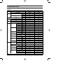
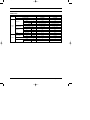
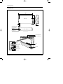
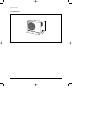
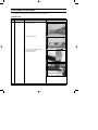
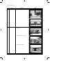
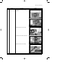
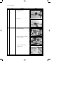
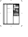
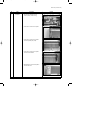
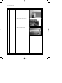
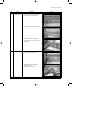
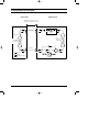
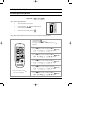
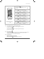
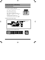
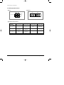
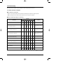
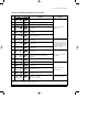
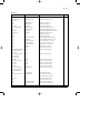
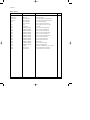
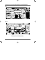
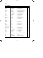
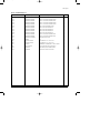
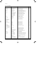
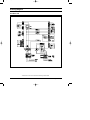
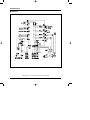
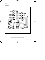
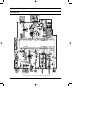
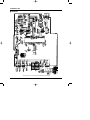
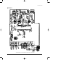
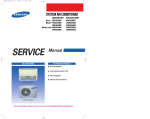
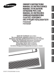
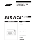
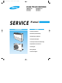
DB98_14413A(1)_co
10/9/03 5:43 PM
Page 3
CEILING TYPE AIR CONDITIONER
INDOOR UNIT
OUTDOOR UNIT
FH052EAMT
FH070EAMT
UH052EAMT
UH070EAMT
SERVICE
AIR CONDITIONER
Manual
CONTENTS
1. Product Specifications
2. Disassembly and Reassembly
3. Refrigerating Cycle Diagram
4. Set Up the Model Option
5. Control Specification & Troubleshooting
6. Exploded Views and Parts List
7. PCB Diagram
8. Wiring Diagram
9. Schematic Diagram
DB98_14413A(1)_1**
10/9/03 5:40 PM
Page 1
1. Product Specifications
1-1 Table
INDOOR UNIT
FH052EAMT
FH070EAMT
OUTDOOR UNIT
UH052EAMT
UH070EAMT
Btu/h
18,700
23,800
W
5,500
7,000
Btu/h
20,400
26,100
W
6,000
7,700
MODEL
Cooling
Capacity
Heating
ø/V/Hz
1/220 ~ 240/50
1/220 ~ 240/50
Cooling
W
1,800
2,400
Heating
W
1,850
2,600
Cooling
A
8.0
11.0
Power Supply
Power Input
Running
Current
A
8.2
11.9
H.H
r.p.m
-
-
Hi
r.p.m
1,020
1,160
Mid
r.p.m
920
1,060
Low
r.p.m
820
960
H.H
m3/min
-
-
Hi
m /min
12
14
Mid
m /min
11
13
Heating
Fan Speed
3
Air Flow
Indoor
Unit
Noise Level(Hi)
(Sound Pressure)
3
Low
m /min
10
12
Cooling(Hi)
dB(A)
48
48
Heating(Hi)
dB(A)
48
48
Type
Slit
Slit
Row x Stages x Fin Pitch
3 x 12 x 1.5mm
3 x 12 x 1.5mm
Type
Sirocco
Sirocco
3
Heat Exchanger
Fan
Dimensions
Weight
Motor Output
W
90
90
H
mm
200
200
W
mm
1,000
1,000
D
mm
650
650
Net / Gross
kg
22 / 26
22 / 26
Hi
r.p.m
750
850
Fan Speed
r.p.m
400
340
m3/min
45
51
Cooling(Hi)
dB(A)
60
60
Heating(Hi)
dB(A)
61
61
Propeller
Propeller
60
73
Type
Rotary
Rotary
Model
NN21VBAMT
NN29VACMT
Low
Air Flow(Hi)
Noise Level
(Sound Pressure)
Outdoor
Unit
Type
Fan
Motor Output
W
Compressor
Motor Output
Protection
Samsung Electronics
kW
1.3
1.9
Internal
Internal
1
DB98_14413A(1)_1**
10/9/03 5:40 PM
Page 2
Table(cont.)
INDOOR UNIT
FH052EAMT
FH070EAMT
OUTDOOR UNIT
UH052EAMT
UH070EAMT
MODEL
R410a
R410a
Charge
g
1,550
1,650
Adding Charge
g/m
25
30
Elec.Expansion Valve
Elec.Expansion Valve
Type
Refrigerant
Control
Outdoor
Unit
Type
Slit
Slit
Row x Stages x Fin Pitch
2 x 28 x 1.5mm
2 x 28 x 1.5mm
Heat Exchanger
H
mm
648
648
W
mm
880
880
Dimensions
Weight
D
mm
310
310
Net / Gross
kg
67 / 72
69 / 74
Liquid
mm(inch)
6.35(1/4")
6.35(1/4")
Gas
mm(inch)
12.7(1/2")
15.88(5/8")
Flare
Flare
Height
m
15
15
Pipe Length
m
30
30
Pipe O.D Size
Piping
Connection Method
Between
2
Samsung Electronics
DB98_14413A(1)_1**
10/9/03 5:40 PM
Page 3
1-2 Dimensions
1-2-1 Indoor Unit
(Unit : mm)
1,000
197
240
Back side
650
922
45
200
50
Pipe outlet (bottom side)
Air intake hole (Ø50)
Wiring hole
Drain hose outlet
Air flow blade(up/ down)
Air flow blade(right/ left)
Remote control
sensor
Defrosting indicator
Air filter
Filter sign indicator
Fan indicator
Auto indicator
Front grille
Timer indicator
Operation indicator
On/Off button
Samsung Electronics
3
DB98_14413A(1)_1**
10/9/03 5:40 PM
Page 4
Product Specifications
1-2-2 Outdoor Unit
880
4
31
0
648
(Unit : mm)
Samsung Electronics
DB98_14413A(1)_1**
10/9/03 5:40 PM
Page 5
2. Disassembly and Reassembly
Stop operation of the air conditioner and remove the power cord before repairing the unit.
2-1 Indoor Unit
No
Parts
1
Electrical
Part
Procedure
Remark
1) Open the grille by pressing 3 position.
(center and both side)
2) Detach the air inlet grille.
3) Open the cover of component electrical
box by removing 3 screws.
(center and both side)
Samsung Electronics
5
DB98_14413A(1)_1**
10/9/03 5:40 PM
Page 6
Disassembly and Reassembly
No
Parts
2
Fan & Motor
Procedure
Remark
1) Detach the screw and untie earth
wire of motor.
2) Disconnect of housing of motor wire.
3) Disconnect the capacitor wire.
6
Samsung Electronics
DB98_14413A(1)_1**
10/9/03 5:40 PM
Page 7
Disassembly and Reassembly
No
Parts
Procedure
Remark
4) Loosen the guard safety by removing
6 screws.
5) Detach the upper case of fan. (2EA)
6) Loosen the 4 screws what is fix the motor.
7) Detach the fan and motor assembly.
Samsung Electronics
7
DB98_14413A(1)_1**
10/9/03 5:40 PM
Page 8
Disassembly and Reassembly
No
Parts
Procedure
Remark
8) Loosen the set fixing bolts.
(with a M3 wrench)
9) Detach the fan.
3
Drain Pan
1) Disconnect the display pcb wire as shown
in picture. (white housing)
2) Disconnect the step motor wire as shown
in picture. (blue housing)
3) Disassemble the hanger bracket by
removing the 1 screw.
8
Samsung Electronics
DB98_14413A(1)_1**
10/9/03 5:40 PM
Page 9
Disassembly and Reassembly
No
Parts
Procedure
Remark
4) Loosen the 3 screws of front side.
5) Disassemble the assembly front
cover part.
6) Disconnect the step motor wire as
shown in picture.
7) Detach the wire clamp fixed in base part.
8) Detach the front cover assembly
completely.
Samsung Electronics
9
DB98_14413A(1)_1**
10/9/03 5:40 PM
Page 10
Disassembly and Reassembly
No
Parts
Procedure
Remark
9) Loosen the screw what is fix with base
part and drain pan. (upper side:2EA)
10) Loosen the screw what is fix with base
part and drain pan.
(lower side:2EA)
11) Detach the drain pan completely.
10
Samsung Electronics
DB98_14413A(1)_1**
10/9/03 5:40 PM
Page 11
Disassembly and Reassembly
No
Parts
4
Evaporator
Procedure
Remark
1) Disconnect the thermistor wire as
shown in picture. (white housing)
2) Loosen the 2 screws shown in picture.
3) Loosen the 2 screws shown in picture
and remove plastic part. (white)
4) Loosen the 2 screws shown in picture
and remove steel bracket.
5) Disassemble the 4 screws steel plate in
rear side of the unit.
Samsung Electronics
11
DB98_14413A(1)_1**
10/9/03 5:40 PM
Page 12
Disassembly and Reassembly
No
Parts
Procedure
Remark
6) Loosen the 2 screws as shown in picture.
7) Detach the plastic cover as shown in
picture.
8) Detach the evaporator assembly.
12
Samsung Electronics
DB98_14413A(1)_1**
10/9/03 5:40 PM
Page 13
Disassembly and Reassembly
No
Parts
5
Stepping Motor
Procedure
Remark
1) Loosen the 4 screws in rear side of front
cover assembly as shown in picture.
2) Loosen the 2 screws as shown in picture.
3) Disassemble the blade and stepping
motor assembly and remove the 2 screws
stepping motor.
6
Display PCB
1) Loosen the 3 screws in rear side of front
cover assembly as shown in picture.
2) Disassemble display PCB assembly
and disconnect wire.
3) Disassemble the display PCB.
Samsung Electronics
13
DB98_14413A(1)_1**
10/9/03 5:40 PM
Page 14
2-2 Outdoor Unit
No
Parts
1
Cabinet
Procedure
Remark
1) Turn off the unit and remove the power
cable.
2) Detach the top cover.
3) Detach the control box cover.
4) Unplug the ass'y cable.
5) Detach the cabi-side.
6) Detach the cabi-front.
● Cautions
When you assemble the parts, check if the
each parts and component electric box are
fixed firmly.
2
14
Fan Motor
&
Propeller Fan
1) Loosen the indicating bolt screw.
2) Disassemble the propeller fan.
Samsung Electronics
DB98_14413A(1)_1**
10/9/03 5:40 PM
Page 15
3. Refrigerating Cycle Diagram
Indoor Unit
Outdoor Unit
❋ Allowable pipe length : Max. 30m
❋ Allowable drop distance : Max. 15m
2-way valve
Liquid pipe
Filter
Filter
Expansion
valve
Capillary tube
Heat
exchanger
(Condensor)
Heat
exchanger
(Evaporator)
Gas pipe
3-way valve
Cooling
Heating
Gas leak check point
Samsung Electronics
4-way valve
Accumulator
Muffler
Compressor
15
DB98_14413A(1)_1**
10/9/03 5:40 PM
Page 16
4. Set Up the Model Option
4-1 Setting Option Setup Method
Option No. :
Step 1 : Enter the Option Setup mode.
1st
Take out the batteries of remote control.
2nd
Press the temperature
insert the battery again.
3rd
Make sure the remocon display shown as
button simultaneously and
.
Step 2 : Enter the Option Setup mode and select your option according to the following procedure.
1
The default value is
Otherwise, push the
.
button to
.
Every time you push the button, the display panel reads
or
repeatedly.
1
2
Push the
2
3
4
button to set the display panel to
.
Every time you push the button, the display panel reads
...
repeatedly.
3
Push the
button to set the display panel to
.
Every time you push the button, the display panel reads
...
repeatedly.
5
6
4
Push the
button to set the display panel to
.
Every time you push the button, the display panel reads
...
repeatedly.
5
Push the
button to set the display panel to
.
Every time you push the button, the display panel reads
...
repeatedly.
✳ Setting is not required if you must
a value which has a
default.
16
6
Push the
button to set the display panel to
.
Every time you push the button, the display panel reads
...
repeatedly.
Samsung Electronics
DB98_14413A(1)_1**
10/9/03 5:44 PM
Page 17
Set Up the Model Option
7
The default value is
Otherwise, push the
.
button to
.
Every time you push the button, the display panel reads
or
repeatedly.
7
8
Push the
8
button to set the display panel to
.
Every time you push the button, the display panel reads
...
repeatedly.
9
10
9
Push the
button to set the display panel to
.
Every time you push the button, the display panel reads
...
repeatedly.
11
12
10
Push the
button to set the display panel to
.
Every time you push the button, the display panel reads
...
repeatedly.
11
Push the
button to set the display panel to
.
Every time you push the button, the display panel reads
...
repeatedly.
12
✳ Setting is not required if you must
a value which has a
default.
Push the
button to set the display panel to
.
Every time you push the button, the display panel reads
...
repeatedly.
Step 3 : Upon completion of the selection, check you made right selections.
Press the Mode Selection key,
The display part shows
and check the display part.
to set the display part to
and check the display part.
.
Press the Mode Selection key,
The display part shows
to set the display part to
.
Step 4 : Pressthe ON/OFF button
.
When pressing the operation ON/OFF key with the direction of remote controller for unit, the sound “Ding” or “Diriring” is
heard and the OPERATION LED lamp is flickering at the same time, then the input of option is completed.
(If the diriring sound isn’t heard, try again pressing the ON/OFF button.)
Step 5 : Unit operation test-run
First, Remove the battery from the remote controller.
Second, Re-insert the battery into the remote controller.
Third, Press ON/OFF button( ) with the direction of remote controller for set.
Samsung Electronics
17
DB98_14413A(1)_1**
10/9/03 5:40 PM
Page 18
Set Up the Model Option
■ OPTION ITEMS
REMOCON
SEG1
SEG2
SEG3
SEG4
SEG5
SEG6
SEG7
SEG8
SEG9 SEG10 SEG11 SEG12
FH070EAMT
0
3
5
4
0
0
1
C
0
0
0
0
FH052EAMT
0
3
5
4
0
0
1
9
0
0
0
0
MODEL
18
Samsung Electronics
DB98_14413A(1)_1**
10/9/03 5:41 PM
Page 19
5. Control Specification & Troubleshooting
5-1 Operation Specification
5-1-1 Tracking process marked on display part
4-1-1
• Left numeral is an address that outdoor unit transfers communication.
-
-
-
... -
Left
Right
(Calling indoor unit)
4-1-1
• Right numeral marks address that is answered.
4-1-1
• During the tracking, left calls indoor unit through
- and checks. At this time
... connected indoor unit set on " " and the indoor unit set
address
marked on right.
Right side mark is marked by when left side is
DISPLAY PART (DS1)
.
(If SW02(MAIN) that set indoor unit address is controlled to "
indoor unit number marked on outdoor unit is marked by "
",
".)
5-1-2 Option set part for Outdoor unit PCB
Setting switch for indoor unit
installation numbers
K2
K4
K1
K3
Data display part
Setting switch for indoor unit installation numbers
Counts of Indoor
Unit Installation
1
2
3
4
5
6
7
8
9
10 11 12 13 14 15
Numbers
of the switch
1
2
3
4
5
6
7
8
9
A
B
C
D
E
F
● Example : When the installed indoor unit is one, control the arrow of switch
forward to ‘0’ or ‘1’ as figure.
Samsung Electronics
19
DB98_14413A(1)_1**
10/9/03 5:41 PM
Page 20
Control Specification & Troubleshooting
5-1-3 Setting Up Option Switches
■ KEY
■ Dispaly
K2
K4
DIS 1
DIS 2
DISPLAY
MODE
CHECK MODE
RESET
K1
SEG 1
SEG 2
SEG 3 SEG 4
K3
■ Summary of KEY functions
Function
K4
K3
K2
K1
Number
(Displayed on SEG 3, 4) (Displayed on SEG 3, 4) (Displayed on SEG 3, 4)
(Displayed
on
SEG
3,
4)
of press times
1
Adding refrigerant at
heating mode
Adding refrigerant at
cooling mode
Reset
Displays data
2
Test operation at
heating mode
Test operation at
cooling mode
-
-
3
End
Pump Down for recovery
of refrigerant
-
-
4
-
End
-
-
✳ Use the K1 only for heat pump models.
20
Samsung Electronics
DB98_14413A(1)_1**
10/9/03 5:41 PM
Page 21
Control Specification & Troubleshooting
5-1-4 Wired remote controller display specification at error occurring
Display
Description
Communication error when there is no signal from outdoor unit to wired
remote controller.
Remarks
Communication error In case
of no signal for 2 minutes
Communication error when there is no answer from wired remote
controller to indoor unit.
Indoor unit float switch error
Indoor unit room temperature sensor open/short error
Indoor unit evaporator temperature sensor open/short error
Indoor unit related error
EEPROM error
EEPROM OPTION error
Fan starting error (1-way cassette model only)
Outdoor unit error display when indoor unit stop
• Outdoor unit sensor error (temperature and pressure)
• Restart failure error
• Self diagnose of Electronic valve opening /closing 6 times
• Reverse phase, E2(Communication error)
Outdoor related error
(Outdoor related error displays
key error)
Overlapping error mark displays error in order, the next error is displayed at error correction.
Samsung Electronics
21
DB98_14413A(1)_1**
10/9/03 5:41 PM
Page 22
5-2 Troubleshooting
When error occurs in air conditioner, error code is displayed on indoor unit display lamp and outdoor unit.
5-2-1 Indoor unit LED error diagnosis
■ Error detection and reoperation
■ ● If error occurs during the operation, badness is indicated by LED flickering and all operation is stopped except LED.
■ ● When reoperating by remote controller and switch determine the error mode after normal operation.
■ Indoor unit LED lamp display at error detecting
LED lamp
Error mode
Remark
Power Reset
Applied indoor unit error display
Error of the indoor unit sensor
(Indoor unit display only during the
operation)
Applied indoor unit error display
Error of the indoor unit pipe sensor
Error of the outdoor unit pipe sensor
(Indoor unit display only during the
operation)
The whole indoor unit error display
Outdoor unit separated Display
(Indoor unit display only during the
operation)
Communication error
(Transmitter, wired remote control)
Indoor unit door
Communication error between indoor units
Indoor unit display
(Display is unrelated with operation)
Freeze prevention control
(Errors occur during 6th detection)
Error of peripherals option set-up
EEPROM ERROR
EEPROM OPTION ERROR
: Flickering
22
: Off
Samsung Electronics
DB98_14413A(1)_1**
10/9/03 5:41 PM
Page 23
Control Specification & Troubleshooting
5-2-2 Outdoor unit display specification at error occurring
Display
No
DIS1
DIS2
Description
1
High discharge temperature(Protection control)
2
High condensor temperature(Protection control)
3
Reverse phase detection error (Protection control)
4
Compressor stop due to frozen evaporator of indoor unit
(every times)
5
Error of momentary power failure(Disappears when the
unit is Off/On)
6
During the defrosting operation
(Heat pump model only)
7
Outdoor temperature SENSOR ERROR
(OPEN/SHORT)
8
Condensor temperature SENSOR ERROR
(OPEN/SHORT)
9
Discharge temperature SENSOR ERROR
(OPEN/SHORT)
10
After tracking completion, system down due to
communication error
11
To mismatch the indoor unit number communicated
with setting indoor unit after 5 times tracking
completion
12
Floating switch error from indoor unit
13
Indoor unit room temperature sensor open/short error
14
Indoor unit evaporator temperature sensor
open/short error
15
Outdoor unit electronic valve opening error
(Detecting over 1 time)
16
Outdoor unit electronic valve closing error
(Detecting over I time)
17
or
flickering
(below -5˚C at cooling),
(over 30˚C at heating)
Remarks
Outdoor protection control
related error
Outdoor sensor related error 1
- The whole outdoor unit sensor
error detection should be done
during the indoor unit operation
only.(But ,transferring to communication data by sensing is
allowed at any time.)
Communication and indoor unit
error related
Indoor/Outdoor unit self
diagnosis related
Operation status display
Display priority order at overlapping error : E1→E4→P0 →P1→P5 →P6 →t1 →t2 →t3 →tu →to →G4 →G5 →E3→qx →rx →K1, 2, 3, 4, 5
- If several indoor unit report the same error, the fast address is priority.
Samsung Electronics
23
DB98_14413A(1)_1**
10/9/03 5:41 PM
Page 24
5-3 Sequence for trouble diagnosis
5-3-1 Outdoor temperature sensor(OPEN/SHORT)
Outdoor unit display
Er → t1 (Outdoor temperature sensor OPEN/SHORT error)
(Operation)
Indoor unit display
How to determine
Reason of error
(Timer)
(Airflow)
(Filter)
Disconnection and short of outdoor temperature sensor
Disconnection or leak of applied sensor
Is not separated the out
temperature sensor connector from
PCB?(CN41)
No
Reoperation
after connection to
connector PCB
Yes
To measure the resistance value
between two terminals after
separating the out temperature sensor
connector from PCB
Yes
At this time, Is not largely
deviate the resistance value from side
table value?
No
Resistance
(kΩ)
70
2.2
60
3.0
50
4.2
40
5.8
30
8.3
20
12.1
10
18.0
0
27.3
-10
43.0
Outdoor unit thermistor
self badness (exchange)
Yes
To check the out temperature
sensor is normal or not by use of
out data display part
➞ To check the temperature data is
normal or not after pressing K4 3 times.
At this time, is occurred the difference
between the out temperature and data?
Temperature
(˚C)
No
PCB and sensor are normal.
To perform the test
operation by use of K2
Yes
Reoperation after PCB exchange
24
Samsung Electronics
DB98_14413A(1)_1**
10/9/03 5:41 PM
Page 25
Control Specification & Troubleshooting
5-3-2 Outdoor heat exchanger temperature sensor error(OPEN/SHORT)
Outdoor unit display
Er → t2 (Outdoor heat exchanger temperature sensor error(OPEN/SHORT)
(Operation)
Indoor unit display
How to determine
Reason of error
(Timer)
(Airflow)
(Filter)
Disconnection and short of outdoor heat exchanger temperature sensor
Disconnection or leak of Applied sensor
Is not separated the out
heat exchanger temperature sensor
connector from PCB?(CN41)
No
Reoperation
after connection to
connector PCB
Yes
To measure the resistance value
between two terminals after separating
the out heat exchanger temperature
sensor connector from PCB
Yes
At this time, Is not largely
deviate the resistance value from side
table value?
No
Resistance
(kΩ)
70
2.2
60
3.0
50
4.2
40
5.8
30
8.3
20
12.1
10
18.0
0
27.3
-10
43.0
Outdoor heat exchanger
temperature self badness
(exchange)
Yes
To check the out temperature
sensor is normal or not by use of
out data display part
➞ To check the temperature data is
normal or not after pressing K4 2 times.
At this time, is occurred the difference
between the out temperature and data?
Temperature
(˚C)
No
PCB and sensor are
normal.
Yes
Reoperation after PCB exchange
Samsung Electronics
25
DB98_14413A(1)_1**
10/9/03 5:41 PM
Page 26
Control Specification & Troubleshooting
5-3-3 Outdoor discharge temperature sensor error(OPEN/SHORT)
Outdoor unit display
Er → t3 (Outdoor discharge temperature sensor OPEN/SHORT error)
(Operation)
Indoor unit display
How to determine
Reason of error
(Timer)
(Airflow)
(Filter)
Disconnection and short of outdoor heat exchanger temperature sensor
Disconnection or leak of Applied sensor
Is not separated the outdoor
discharge temperature sensor connector
from PCB?(CN42)
No
Re-operation
after connection to
connector PCB
Yes
To measure the resistance value
between two terminals after separating
the outdoor discharge temperature
sensor connector from PCB
Yes
At this time, Is not largely
deviate the resistance value from
side table value?
No
Outdoor heat exchanger
temperature self badness
(exchange)
Yes
To check the out temperature
sensor is normal or not by use of out
data display part
➞ To check the temperature data is
normal or not after pressing K4 1 times.
At this time, is occurred the difference
between the out temperature and data?
Yes
Temperature
(˚C)
Resistance
(kΩ)
130
8.9
120
11.2
100
18.5
80
32
60
59
25
200
20
242
10
362
0
553
-10
No
PCB and sensor are normal.
To perform the test
operation by use of K2
Re-operation after PCB exchange
26
Samsung Electronics
DB98_14413A(1)_1**
10/9/03 5:41 PM
Page 27
Control Specification & Troubleshooting
5-3-4 Communication error during the operation
Outdoor unit display
Er → E1 (Communication error during the operation)
(Operation)
Indoor unit display
Disconnection
and short of
communication lines
Reason of error
(Timer)
(Airflow)
(Filter)
Disconnection and short of outdoor heat exchanger temperature sensor
Disconnection or leak of Applied sensor
To check the display after
pressing the reset key on outdoor PCB
Multi type
After 2 minutes, to check if PCB address
setting of indoor unit displayed th
communication error among indoor units is
overlapped or not.
(If the indoor unit address is overlapped, the
communication error is occurred.)
- In this case, the communication error is
occurred to over two indoor units set
wrong.
No
When tracking, is there any
indoor answer from display part?
Yes
To measure the 2 lines of outdoor side
by scope after removing the
communication line connecting from
outdoor unit to indoor unit.
If address is no fault,
to exchange the indoor unit PCB after
communication line check.
At this time, is the voltage
between lines spherical wave over DC ±0.7V
like below figure?
No
Yes
To exchange PCB after checking
the outdoor unit communication line
and connector
After connecting again the communication
line connecting from outdoor unit to indoor unit,
to remove the communication
connector on indoor unit PCB, and find the
indoor unit preventing communication
through connecting the communication
connectors each by each, and then exchange
the indoor unit PCB after line check.
Good
Bad
+0.7V
-0.7V
Samsung Electronics
27
DB98_14413A(1)_1**
10/9/03 5:41 PM
Page 28
Control Specification & Troubleshooting
5-3-5 Communication error between indoor and outdoor after initial power input.
Outdoor unit display
Er → E2 (Tracking error)
(Operation)
Indoor unit display
How to determine
Reason of error
(Timer)
(Airflow)
(Filter)
Mismatching the communicating indoor unit and setting switch indoor numbers When outdoor tracking
Communication error between the indoor unit and outdoor unit, and installation number switch
setting miss
To check the setting value of
indoor unit installation number setting
switch of outdoor PCB and actual indoor unit
installation numbers
Is equal indoor unit actual
installation number and installation
number setting switch?
If the indoor unit number installed is one, set the
outdoor unit switch forward to "0", "1"
➞ "0" and "1" spell the connection of an indoor unit.
No
Yes
After setting the indoor unit installation setting
number switch correctly, Re-perform the
tracking by pressing the reset key K3 of
outdoor unit PCB
To press the reset key K3 of outdoor unit
PCB and check the display to check the
number of indoor units answering to the
tracking
When tracking, is there any
indoor answer from display part?
Yes
To measure the 2 lines of outdoor unit side by
use of scope after removing the communication
line connecting from outdoor unit to indoor unit
At this time, is the voltage
between lines spherical wave over
DC ±0.7V ?
Yes
No
Multi type
After 2 minutes, to check if PCB address setting
of indoor unit displayed the communication error
among indoor units is overlapped or not .
(If the indoor unit address is overlapped, the
communication error is occurred.)
- In this case, the communication error is
occurred to over two indoor units set wrong
If address is no fault,
to exchange the indoor unit PCB after
communication line check.
After connecting again the communication line
connecting from outdoor unit to indoor unit,
to check this communication is reverse or not,
and if there is no fault, to find the indoor unit
preventing communication through connecting
indoor units each by each, and then
exchange the indoor unit PCB after line check
28
Samsung Electronics
DB98_14413A(1)_1**
10/9/03 5:41 PM
Page 29
Control Specification & Troubleshooting
5-3-6 Indoor floating switching error
Outdoor unit display
Er → E3 (Indoor floating switching error )
(Operation)
Indoor unit display
How to determine
(Timer)
(Airflow)
(Filter)
The status continues over 1 minute that indoor unit floating switch is opened.
The rising of water level of drain pan due to the disorder of indoor unit drain pump,
Reason of error
the badness of detection sensor
Is the indoor unit
error occurred cassette type?
No
Refer to the drain pump
option in the next page.
Yes
Is the resistance value ∞
when measuring the resistance value
of two terminal after taking out the floating
switch connector connected to indoor
unit PCB? (Open status)
No
To re-assembly the floating switch
connector and perform the reset of
outdoor power(Required the reset of
indoor unit power)
Yes
Is the same error occurred?
Is much the water of drain pan ?
Yes
No
Yes
To exchange the indoor unit PCB
No
Normal operation
To reset the indoor unit power
and check the drain pump operation
To determine the floating switch
bad To reset the indoor unit
power after exchange
No
Is operated the drain pump?
Yes
Is lowing the water level?
No
Is the terminal voltage
of drain pump PCB about
AC 220V?
No
Yes
Yes
To exchange the drain pump
To exchange the indoor unit PCB
Normal operation
To exchange the drain pump
Samsung Electronics
❋ Note : E3 error should be released when
indoor unit power is reset.
29
DB98_14413A(1)_1**
10/9/03 5:41 PM
Page 30
6. Exploded Views and Parts List
6-1 Indoor Unit
24
26
30
39
29
38
41
28
4
5
27
17
2
40
42
18
1
19
8 9 10
20
35
11 12
22
6
31
32
23
16
3
34
13
21
43
25
7
36
37
33
45-7
45-6
45-3
15
45-4
45-5
45-2
45-8
45
45-1
14
44
You can search for the updated part code
number through the ITSELF.
URL : http://itself.sec.samsung.co.kr
30
Samsung Electronics
DB98_14413A(1)_1**
10/9/03 5:41 PM
Page 31
Exploded Views and Parts List
■
Parts List
No.
Code No.
Description
Q'TY
Specification
FH052EAMT
FH070EAMT
1
DB64-00682A
CABI BASE
ABS
1
1
2
DB63-00601A
COVER PIPE
ABS
1
1
3
DB63-00602A
COVER SIDE
ABS
2
2
4
DB61-01149A
PLATE HANGER LF
SGCC-M
1
1
5
DB61-01150A
PLATE HANGER RH
SGCC-M
1
1
6
DB61-01155A
BRACKET COVER PIPE
SGCC-M
1
1
7
DB64-00683A
CABI FRONT
ABS(SILK PRINT)
1
1
8
DB63-00606C
COVER DISPLAY A
ABS(SILK PRINT)
1
1
9
DB63-00607A
COVER DISPLAY B
PC
1
1
10
DB63-00604A
COVER LED
ABS
1
1
11
DB93-01476B
DISPLAY PCB IN
PCB
1
1
12
DB61-01159A
CASE DISPLAY PCB
ABS
1
1
13
DB66-00451A
LATCH PUSH
ASS'Y
3
3
14
DB64-00684A
INLET GRILLE
ABS
1
1
15
DB63-00610A
FILTER AIR
PP
2
2
16
DB61-01153A
PLATE HANGER FRONT
SGCC-M
1
1
17
DB61-01156A
BRACKET OUTLET
ABS
1
1
18
DB31-00158A
BLADE V
ABS
12
12
19
DB31-00159A
BLADE CONNECTOR V
ABS
2
2
20
DB31-00164A
BLADE CONNECTOR H
ABS
2
2
21
DB31-00157A
BLADE H
ABS
1
1
22
DB31-10153D
SWING MOTOR IN
ASS'Y
1
1
23
DB61-01352A
BRACKET DRAIN
SGCC-M
1
1
24
DB67-00258A
DRAIN SUB LF
SGCC-M
1
1
25
DB67-00259A
DRAIN SUB RH
ABS
1
1
26
DB75-00221B
EVAPORATOR
ASS'Y
1
1
27
DB96-02171A
ASS'Y COLLECTOR
ASS'Y
-
1
DB96-02250A
ASS'Y COLLECTOR
ASS'Y
1
-
28
DB96-02170A
ASS'Y INLET
ASS'Y
1
1
29
DB61-01157A
BRACKET EVAP
SGCC-M
1
1
30
DB63-00624A
COVER EVAP
ABS
1
1
31
DB31-00179A
MOTOR FAN
ASS'Y(OSME-254SAC)
1
1
32
DB67-00260A
BLOWER
ABS
2
2
33
DB61-01160A
CASE FAN UP
ABS
2
2
34
DB63-00611A
COVER MOTOR
SGCC-M
2
2
35
DB61-01162A
HOLDER MOTOR
SGCC-M
4
4
36
DB63-00738A
GUARD SAFETY
HSWR
1
1
37
DB63-00739A
GUARD FAN
HSWR
2
2
38
DB67-00257A
DRAIN PAN
ABS
1
1
39
DB67-00275A
DRAIN PARTITION
ABS
2
2
40
DB69-00617A
CUSHION DRAIN A
EPS(25FOAM-PS)
1
1
41
DB69-00714A
CUSHION DRAIN B
EPS(25FOAM-PS)
1
1
Samsung Electronics
31
DB98_14413A(1)_1**
10/9/03 5:41 PM
Page 32
Exploded Views and Parts List
■
Parts List(cont.)
No.
Code No.
Description
Q'TY
Specification
ASS'Y
FH052EAMT
FH070EAMT
1
1
42
DB94-00062B
ASS'Y DRAIN HOSE
43
DB32-00082A
THERMISTOR EVAP
ASS'Y
1
1
44
DB63-00605A
COVER CONTROL
ABS(UL94-V0)
1
1
45
DB93-02409A
ASS'Y CONTROL IN
ASS'Y
-
1
DB93-02409B
ASS'Y CONTROL IN
ASS'Y
1
-
45-1
DB61-01154A
BASE CONTROL
SGCC-M
1
1
45-2
DB61-01220A
CASE PCB MAIN
ABS(UL94-V0)
1
1
45-3
DB93-02268A
CEILING EU,PCB ASSY
PCB
1
1
45-4
DB65-00105G
TERMINAL BLOCK 6P
DAF-S6P
1
1
45-5
DB65-00004R
TERMINAL BLOCK 4P
DAF-S4P
1
1
45-6
DB26-10065B
TRANS POWER
ASSY
1
1
45-7
45-8
32
2301-001368
CAPACITOR
5uF 450VAC
-
1
2301-001369
CAPACITOR
3uF 450VAC
1
-
DB61-00250A
CLAMP WIRE
NYLON
2
2
Samsung Electronics
DB98_14413A(1)_1**
10/9/03 5:41 PM
Page 33
MEMO
Samsung Electronics
33
DB98_14413A(1)_1**
10/9/03 5:41 PM
Page 34
6-2 Outdoor Unit
20
1
2
21
22
15
23
16
5
4
24
8
13
25
9-7
9-1
9-3
10
3
11
9-6
9
9-2
9-5
14
12
9-4
17
19
26
18
6
7
34
Samsung Electronics
DB98_14413A(1)_1**
10/9/03 5:41 PM
Page 35
Exploded Views and Parts List
■
Parts List
No.
Code No.
Description
Q'TY
Specification
UH052EAMT UH070EAMT
1
DB90-01363A
ASS'Y-COVER TOP
ASS'Y
1
1
2
DB90-01293A
ASS'Y CABI-FRONT
ASS'Y,LOGO
1
1
3
DB67-00140A
FAN-PROPELLER
AS+GF20%,OD460,3BLADE
1
1
1
4
DB61-01167A
BRACKET-MOTOR
SGCC-M,T1.6
1
5
DB67-00261A
PARTITION
SGCC-M,T0.8
1
1
6
DB95-00454A
ASS'Y COMP
SIAM,NN29VACMT
-
1
DB95-00455A
ASS'Y COMP
SIAM,NN21VBAMT
1
-
DB95-30013T
ASS'Y HEATER COMP
40W
1
1
7
8
DB31-00216A
MOTOR-FAN
OSEM-886SRC(S509)
-
1
DB31-00027G
MOTOR-FAN
OSEM-906SRC(S507)
1
-
DB93-02410A
ASS'Y CONTROL OUT
ASS'Y
-
1
DB93-02410B
ASS'Y CONTROL OUT
ASS'Y
1
-
9-1
DB26-10070A
TRANS-POWER
AC230V,DC17V
1
1
9-2
DB65-00112A
TERMINAL BLOCK-6P
35A 4P,25A 2P
1
1
9-3
3501-001204
MAGNETIC-SWITCH
MUF20CF,2A
1
1
9-4
DB61-30625A
BRACKET-TERMINAL
SGCC-M
1
1
9-5
DB93-40264B
ASS'Y CONTROL BOX OUT
ASHT-1805ER
1
1
9-6
DB61-00152A
CASE-PCB-OUT
T2.5,ABS,BLK
1
1
9-7
2301-001369
CAPACITOR-FAN
3uF/450VAC
1
1
10
2501-001236
CAPACITOR-COMP
30uF/450VAC
-
1
2501-001235
CAPACITOR-COMP
25uF/450VAC
-
1
2501-001240
CAPACITOR-COMP
50uF/450VAC
1
-
9
11
DB32-00021F
THERMISTOR
AWG22,L470,L550
1
1
12
DB32-00071C
THERMISTOR
AWG22,L600
1
1
13
DB61-01685A
BAND-CAPACITOR
SGCC-M
-
1
DB69-60008A
BAND-CAPACITOR
SGCC-M
1
-
14
DB93-00185D
ASS'Y PCB MAIN-OUT
CEILING OUTDOOR PCB
1
-
DB93-00185E
ASS'Y PCB MAIN-OUT
CEILING OUTDOOR PCB
-
1
15
DB63-10490A
COVER-CONTROL
ABS,SC-900073R
1
1
16
DB90-01292B
CABINET-SIDE RH
SECC-P,T0.8
1
1
17
DB62-01471A
INSU-CLOTH COMP
UH070EAMT
-
1
DB62-02295A
INSU-CLOTH COMP
UH052EAMT
1
-
18
19
DB96-02876A
ASS'Y 4WAY VALVE
ASS'Y
-
1
DB96-02877A
ASS'Y 4WAY VALVE
ASS'Y
1
-
DB96-02896A
ASS'Y EEV VALVE
ASS'Y
-
1
DB96-02896B
ASS'Y EEV VALVE
ASS'Y
1
-
20
DB63-00613A
GUARD-COND
SECC-P,T1.6
1
1
21
DB61-01221A
GUIDE-SCREEN
P.E.H 100%,T2.5,1015x615,BLK
1
1
22
DB63-00320A
GUARD-FAN
HSWR,460
1
1
23
DB75-00251A
COND
UH070EAMT,UH052EAMT
1
1
24
DB96-02936A
ASS'Y COLLECTOR IN
ASS'Y
1
1
25
DB96-02937A
ASS'Y COLLECTOR OUT
ASS'Y
1
1
26
DB90-01291A
ASS'Y BASE OUT
ASS'Y
1
1
Samsung Electronics
35
DB98_14413A(1)_1**
10/9/03 5:41 PM
Page 36
7. PCB Diagram
7-1 Indoor Unit (Code No :DB93-02268A)
■ TOP
36
■ BOTTOM
Samsung Electronics
DB98_14413A(1)_1**
10/9/03 5:41 PM
Page 37
PCB Diagram
■
Parts List
Location No.
Description
Specification
Q'TY
D904,D909,D914,D919
DIODE-SWITCHING
1N4148,100V,200mA,DO-35,TP
4
D900~D903,D905~D913
DIODE-SWITCHING
RLS4148,100V,450mA,LL-34,TP
17
D105
DIODE-RECTIFIER
1N4007,1000V,1A,DO-41,TP
1
BD71
DIODE-BRIDGE
DF06S,600V,1A,SMD-4,TP
1
CD31,CD32
DIODE-TVS
SAC5.0,7.6/-/-V,500W,DO-15
2
Q201,Q202,Q601,Q602
TR-SMALL SIGNAL
2SC2412K,NPN,200mW,SOT-23,TP,1
4
Q603
TR-SMALL SIGNAL
MMST2907A,PNP,200mW,SOT-23,TP,100-
1
Q901~Q903
TR-DIGITAL
DTA114EKA,PNP,200MW,10K/10K,SOT-23,TP
3
IC05,IC06,IC08
TR-ARRAY
2003,NPN,7,1W,SOP-16,ST,1000
3
LED02
LED
ROUND,YEL,5mm,585nm
1
LED01
LED
TR,LED,1PCS,130-260%
1
IC19
IC-BUS TRANSCEIVER
485,DIP,8P,300MIL,SINGLE,ST,PLASTIC
1
IC51
IC-EEPROM
93LC56,128x16Bit,SOP,8P,150MIL,-,2.5V,-
1
IC03
IC-VOLTAGE COMP.
7533,TO-92,3P,-,SINGLE,-,-,PLASTIC
1
IC01
IC-POSI.FIXED REG.
7812A,TO-220,3P,-,PLASTIC,11.5
1
D915~D918
IC02
IC-POSI.FIXED REG.
7805,TO-220,3P,-,PLASTIC,4.8/5
1
VA71
VARISTOR
560V,2500A,17.5x7.5mm,TP
1
R301
R-CHIP
120ohm,5%,1/10W,DA,TP,2012
1
R606,R203,R302,R303,R503
R-CHIP
560ohm,5%,1/10W,DA,TP,2012
14
R-CHIP
1Kohm,5%,1/10W,DA,TP,2012
13
R202,R610
R-CHIP
3.3Kohm,5%,1/10W,DA,TP,2012
2
R402,R404,R502,R901
R-CHIP
330ohm,5%,1/10W,DA,TP,2012
4
R604,R605
R-CHIP
470ohm,5%,1/10W,DA,TP,2012
2
R511,R512
R-CHIP
47Kohm,5%,1/10W,DA,TP,2012
2
R401,R403
R-CHIP
6.8Kohm,1%,1/10W,DA,TP,2012
2
C102,C104,C201~C203
C-CERAMIC,CHIP
100nF,+80-20%,50V,Y5V,TP,2012
19
C901
C-CERAMIC,CHIP
1nF,10%,50V,X7R,TP,2012,-
1
C204,C205,C301,C911~C915
C-CERAMIC,CHIP
10nF,+80-20%,50V,Y5V,TP,2012
8
C105
C-AL
470uF,20%,25V,GP,TP,10x12.5mm
1
R602,R608,R609,R903
R911~R915
R04,201,R204,R205,R206
R601,R603,R607
R813~R816,R902
C302~C306,C501~C505
C805~C806,C808,C902
C101,C103
C-AL
1000uF,20%,35V,GP,TP,13x25,5
2
C601
C-AL
47uF,20%,50V,GP,TP,6.3x11,2.5
1
X301
RESONATOR-CERAMIC
10MHz,0.5%,TP,10.0x5.0x8.0mm
1
FT71
FILTER-EMI AC LINE
250V,1A,-,220000PF,20.5x20.5x32
1
Samsung Electronics
37
DB98_14413A(1)_1**
10/9/03 5:41 PM
Page 38
PCB Diagram
■
Parts List(cont.)
Location No.
Description
Specification
Q'TY
BZ61
BUZZER-PIEZO
85DB,12V,-,2.0KHZ,ST
1
SW03~SW05
SWITCH-DIP
5V DC,100mA,SLIDE,-
3
R78,R79,RY72
RELAY-MINIATURE
12VDC,200MW,3000MA,1FORMA,10MS,10M
3
RY73~RY76
RELAY-MINIATURE
12VDC,200MW,5000MA,1FORMA,10MS,5MS
4
RY01
RELAY-MINIATURE
12V,-,11.7MA,DPDT,4MS,4MS
1
FUSE-CARTRIDGE
250V,3.15A,TIME-LAG,GLASS,5x20mm
1
F702
FUSE
250V,1.6A,TIME-LAG,PLASTIC,8.4x7.6mm
1
F701
FUSE-BLOCK
500V,-,100M
1
CN51
CONNECTOR-HEADER
BOX,2P,1R,2.5mm,STRAIGHT,SN,WHT
1
CN31
CONNECTOR-HEADER
1WALL,2P,1R,3.96mm,STRAIGHT,SN
1
CN43
CONNECTOR-HEADER
1WALL,2P,1R,3.96mm,STRAIGHT,SN
1
CN72
CONNECTOR-HEADER
1WALL,2P,1R,7.92mm,STRAIGHT,SN,WH
1
CN71
CONNECTOR-HEADER
1WALL,7P,1R,3.96mm,STRAIGHT,SN
1
CN74
CONNECTOR-HEADER
1WALL,5P,1R,7.92mm,STRAIGHT,SN,WH
1
CN11
CONNECTOR-HEADER
BOX,3P,1R,2.5mm,STRAIGHT,SN
1
CN41
CONNECTOR-HEADER
BOX,4P,1R,2.5mm,STRAIGHT,SN
1
CN61
CONNECTOR-HEADER
BOX,6P,1R,2.5mm,STRAIGHT,SN
1
CN44
CONNECTOR-HEADER
YW396-04V,WHT
1
CN33
CONNECTOR-HEADER
BOX,5P,1R,2mm,STRAIGHT,SN
1
CN91
CONNECTOR-HEADER
BOX,9P,1R,2mm,STRAIGHT,SN
1
IC04
IC MICOM
MB89538AP-101,MB89538AP-101,64P,+5V,10MHZ
1
SW01
SWITCH-DIGITAL
PT65 103,ROTARY DIP,-,DC24V MAX,0.4
1
SW02
SWITCH-DIGITAL
PT65 503,ROTARY DIP,-,DC24V MAX,0.4
1
38
Samsung Electronics
DB98_14413A(1)_1**
10/9/03 5:41 PM
Page 39
7-2 Outdoor Unit (Code No:DB93-01855D;UH052EAMT / DB93-01855E;UH070EAMT)
■ TOP
■ BOTTOM
✳ The figure of PCB Pattern is common UH052EAMT and UH070EAMT.
✳ Only part list is different from between UH052EAMT and UH070EAMT.
Samsung Electronics
39
DB98_14413A(1)_1**
10/9/03 5:41 PM
Page 40
PCB Diagram
■
Parts List(UH052EAMT)
Location No.
Description
Specification
Q'TY
D201,D901~D916
DIODE-SWITCHING
RLS4148,100V,200MA,SOD-80C,TP
17
D101~D105
DIODE-RECTIFIER
1N4007,1000V,1A,DO-41,TP
5
CD31~CD32
DIODE-TVS
SAC5.0,7.6/-/-V,500W,DO-15
2
Q201
TR-SMALL SIGNAL
2SC2412K,NPN,200mW,SOT-23,TP,1
1
Q901~D904
TR-DIGITAL
DTA114EKA,PNP,200MW,10K/10K,SOT-23,TP
4
Q101
TR-DIGITAL
KSR1102,NPN,200MW,10K/10K,SOT-23,TP
1
IC05~IC07
IC-DARLINGTON DRIVER
KID65003AP,DIP,16PIN,300MIL,H
3
IC09
IC-BUS TRANSCEIVER
485,DIP,8P,300MIL,SINGLE,ST,PLASTIC
1
IC03
IC-VOLTAGE COMP.
7533,TO-92,3P,-,SINGLE,-,-,PLASTIC
1
IC01
IC-POSI.FIXED REG.
7812A,TO-220,3P,-,PLASTIC,11.5
1
IC02
IC-POSI.FIXED REG.
7805,TO-220,3P,-,PLASTIC,4.8/5
1
VA72,VA73
VARISTOR
470V,4500A,17x12mm,BK
2
VA71
VARISTOR
560V,2500A,17.5x7.5mm,TP
1
RJ03
R-CARBON
12Kohm,5%,1/4W,AA,TP,2.4x6.4mm
1
K13~K16,RJ01
R-CARBON
0ohm,5%,1/4W,AA,TP,2.4x6.4mm
5
R301
R-CHIP
120ohm,5%,1/8W,TP,2012
1
R201,R302,R303
R-CHIP
10Kohm,5%,1/8W,TP,2012
20
R-CHIP
18Kohm,1%,1/8W,TP,2012
2
R312~319,R513~R517
R901~R904
R402,R403
R203~R205,R905~R911
R-CHIP
1Kohm,5%,1/8W,TP,2012
10
R401
R-CHIP
24Kohm,1%,1/8W,TP,2012
1
R202
R-CHIP
3.3Kohm,5%,1/8W,TP,2012
1
R404~R406
R-CHIP
330ohm,5%,1/8W,TP,2012
3
C102,C104,C201
C-CER,CHIP
100nF,+80-20%,50V,Y5V,TP,2012
20
C202,C301,C901~C904
C-CER,CHIP
10nF,+80-20%,50V,Y5V,TP,2012
6
C105
C-AL
470uF,20%,25V,GP,TP,10x12.5mm
1
C101,C103
C-AL
1000uF,20%,35V,GP,TP,13x25,5
2
X501
RESONATOR-CERAMIC
10MHZ,0.5%,BK,8x3x5.5mm
1
FT71
FILTER-EMI AC LINE
250V,1A,UL/CSA/TUV/SEMKO,100000
1
C302~C308,C401~C403
C801~C804,C905~C907
K1~K4
SWITCH-PUSH
125V,1A,SPDT,ON-ON,-
4
SW02,SW03
SWITCH-DIP
5V DC,100mA,SLIDE,-
2
RY71~RY77
RELAY-MINIATURE
12VDC,200MW,3000MA,1FORMA,10MS,10M
7
F701_1
FUSE-CARTRIDGE
250V,5A,FAST-ACTING,GLASS,5.2x20mm
1
F101
FUSE
250V,1.6A,TIME-LAG,PLASTIC,8.4x7.6mm
1
F701
FUSE-BLOCK
500V,-,100M
1
CN42
CONNECTOR-HEADER
BOX,2P,1R,2.5mm,STRAIGHT,SN,WHT
1
CN12
CONNECTOR-HEADER
1WALL,2P,1R,3.96mm,STRAIGHT,SN
1
40
Samsung Electronics
DB98_14413A(1)_1**
10/9/03 5:41 PM
Page 41
PCB Diagram
■
Parts List(UH052EAMT)(cont.)
Location No.
Description
Specification
Q'TY
CN31
CONNECTOR-HEADER
1WALL,2P,1R,3.96mm,STRAIGHT,SN
1
CN77
CONNECTOR-HEADER
1WALL,2P,1R,7.92mm,STRAIGHT,SN,WH
1
CN72
CONNECTOR-HEADER
1WALL,3P,1R,7.92mm,STRAIGHT,SN,BL
1
CN73
CONNECTOR-HEADER
1WALL,3P,1R,7.92mm,STRAIGHT,SN,WH
1
CN75
CONNECTOR-HEADER
1WALL,4P,1R,7.92mm,STRAIGHT,SN,WH
1
CN70
CONNECTOR-HEADER
BOX,1P,1R,6mm,STRAIGHT,NI,WHT
1
CN11
CONNECTOR-HEADER
BOX,3P,1R,2.5mm,STRAIGHT,SN
1
CN41
CONNECTOR-HEADER
BOX,4P,1R,2.5mm,STRAIGHT,SN
1
CN61
CONNECTOR-HEADER
BOX,5P,1R,2.5mm,STRAIGHT,SN
1
CN60
CONNECTOR-HEADER
BOX,6P,1R,2.5mm,STRAIGHT,SN
1
CN71
CONNECTOR-HEADER
1WALL,2P,1R,7.92mm,STRAIGHT,SN,BL
1
CN74
CONNECTOR-HEADER
1WALL,2P,1R,7.92mm,STRAIGHT,SN,YE
1
GT-2
CONNECTOR-TERMINAL
PIN,MALE,#18-22,2.35mm
1
RJ02
JUMPER
7.5
1
DIS1
LED DISPLAY-7SEG
ELD-306GWA,-,2,14,-,15*15.5*7.2,G
1
DIS2
LED DISPLAY-7SEG
ELD-306GWA,-,2,14,-,15*15.5*7.2,G
1
IC04
IC MICOM
MB89538AP-101,MB89538AP-101,64P,+5V,10MHz
1
SW1
SWITCH-DIGITAL
PT65 103,ROTARY DIP,-,DC24V MAX,0.4
1
DS71
POSISTOR
DSA-332MA,2pF MAX,100MOhm,ASM-3
1
RJ04
R-CARBON
3.3Kohm,5%,1/4W,AA,TP,2.4x6.4mm
1
Samsung Electronics
41
DB98_14413A(1)_1**
10/9/03 5:41 PM
Page 42
PCB Diagram
■
Parts List(UH070EAMT)
Location No.
Description
Specification
Q'TY
D201,D901~D916
DIODE-SWITCHING
RLS4148,100V,200MA,SOD-80C,TP
17
D101~D105
DIODE-RECTIFIER
1N4007,1000V,1A,DO-41,TP
5
CD31,CD32
DIODE-TVS
SAC5.0,7.6/-/-V,500W,DO-15
2
Q201
TR-SMALL SIGNAL
2SC2412K,NPN,200mW,SOT-23,TP,1
1
Q901~Q904
TR-DIGITAL
DTA114EKA,PNP,200MW,10K/10K,SOT-23,TP
4
Q101
TR-DIGITAL
KSR1102,NPN,200MW,10K/10K,SOT-23,TP
1
IC05~IC07
IC-DARLINGTON DRIVER
KID65003AP,DIP,16PIN,300MIL,H
3
IC09
IC-BUS TRANSCEIVER
485,DIP,8P,300MIL,SINGLE,ST,PLASTIC
1
IC03
IC-VOLTAGE COMP.
7533,TO-92,3P,-,SINGLE,-,-,PLASTIC
1
IC01
IC-POSI.FIXED REG.
7812A,TO-220,3P,-,PLASTIC,11.5
1
IC02
IC-POSI.FIXED REG.
7805,TO-220,3P,-,PLASTIC,4.8/5
1
VA72,VA73
VARISTOR
470V,4500A,17x12mm,BK
2
VA71
VARISTOR
560V,2500A,17.5x7.5mm,TP
1
K13~K16,RJ01
R-CARBON
0ohm,5%,1/4W,AA,TP,2.4x6.4mm
5
R301
R-CHIP
120ohm,5%,1/8W,TP,2012
1
R201,R302~R303
R-CHIP
10Kohm,5%,1/8W,TP,2012
20
R402,R403
R-CHIP
18Kohm,1%,1/8W,TP,2012
2
R203~R205,R905~R911
R-CHIP
1Kohm,5%,1/8W,TP,2012
10
R401
R-CHIP
24Kohm,1%,1/8W,TP,2012
1
R202
R-CHIP
3.3Kohm,5%,1/8W,TP,2012
1
R404~R406
R-CHIP
330ohm,5%,1/8W,TP,2012
3
C102,C104,C201
C-CER,CHIP
100nF,+80-20%,50V,Y5V,TP,2012
20
C202,C301,C901~C904
C-CER,CHIP
10nF,+80-20%,50V,Y5V,TP,2012
6
C105
C-AL
470uF,20%,25V,GP,TP,10x12.5mm
1
C101,C103
C-AL
1000uF,20%,35V,GP,TP,13x25,5
2
X501
RESONATOR-CERAMIC
10MHZ,0.5%,BK,8x3x5.5mm
1
FT71
FILTER-EMI AC LINE
250V,1A,UL/CSA/TUV/SEMKO,100000
1
K1~K4
SWITCH-PUSH
125V,1A,SPDT,ON-ON,-
4
SW02,SW03
SWITCH-DIP
5V DC,100mA,SLIDE,-
2
RY71,R76,R77
RELAY-MINIATURE
12VDC,200MW,3000MA,1FORMA,10MS,10M
3
RY72~RY75
RELAY-MINIATURE
12VDC,200MW,5000MA,1FORMA,10MS,5MS
4
F701_1
FUSE-CARTRIDGE
250V,5A,FAST-ACTING,GLASS,5.2x20mm
1
F101
FUSE
250V,1.6A,TIME-LAG,PLASTIC,8.4x7.6mm
1
F701
FUSE-BLOCK
500V,-,100M
1
CN42
CONNECTOR-HEADER
BOX,2P,1R,2.5mm,STRAIGHT,SN,WHT
1
CN12
CONNECTOR-HEADER
1WALL,2P,1R,3.96mm,STRAIGHT,SN
1
R312~R319,R513~R517
R901~R904
C302~C308,C401~C403
C801~C804,C905~C907
42
Samsung Electronics
DB98_14413A(1)_1**
10/9/03 5:41 PM
Page 43
PCB Diagram
■
Parts List(UH070EAMT)(cont.)
Location No.
Description
Specification
Q'TY
CN31
CONNECTOR-HEADER
1WALL,2P,1R,3.96mm,STRAIGHT,SN
1
CN77
CONNECTOR-HEADER
1WALL,2P,1R,7.92mm,STRAIGHT,SN,WH
1
CN72
CONNECTOR-HEADER
1WALL,3P,1R,7.92mm,STRAIGHT,SN,BL
1
CN73
CONNECTOR-HEADER
1WALL,3P,1R,7.92mm,STRAIGHT,SN,WH
1
CN75
CONNECTOR-HEADER
1WALL,4P,1R,7.92mm,STRAIGHT,SN,WH
1
CN70
CONNECTOR-HEADER
BOX,1P,1R,6mm,STRAIGHT,NI,WHT
1
CN11
CONNECTOR-HEADER
BOX,3P,1R,2.5mm,STRAIGHT,SN
1
CN41
CONNECTOR-HEADER
BOX,4P,1R,2.5mm,STRAIGHT,SN
1
CN61
CONNECTOR-HEADER
BOX,5P,1R,2.5mm,STRAIGHT,SN
1
CN60
CONNECTOR-HEADER
BOX,6P,1R,2.5mm,STRAIGHT,SN
1
CN71
CONNECTOR-HEADER
1WALL,2P,1R,7.92mm,STRAIGHT,SN,BL
1
CN74
CONNECTOR-HEADER
1WALL,2P,1R,7.92mm,STRAIGHT,SN,YE
1
GT-2
CONNECTOR-TERMINAL
PIN,MALE,#18-22,2.35mm
1
RJ02
JUMPER
7.5
1
DIS1
LED DISPLAY-7SEG
ELD-306GWA,-,2,14,-,15*15.5*7.2,G
1
DIS2
LED DISPLAY-7SEG
ELD-306GWA,-,2,14,-,15*15.5*7.2,G
1
IC04
IC MICOM
MB89538AP-101,MB89538AP-101,64P,+5V,10MHz
1
SW1
SWITCH-DIGITAL
PT65 103,ROTARY DIP,-,DC24V MAX,0.4
1
DS71
POSISTOR
DSA-332MA,2pF MAX,100MOhm,ASM-3
1
RJ03
R-CARBON
12Kohm,5%,1/4W,AA,TP,2.4x6.4mm
1
RJ04
R-CARBON
3Kohm,5%,1/4W,AA,TP,2.4x6.4mm
1
Samsung Electronics
43
DB98_14413A(1)_1**
10/9/03 5:41 PM
Page 44
8. Wiring Diagram
8-1 Indoor Unit
This Document can not be used without Samsung's authorization.
44
Samsung Electronics
DB98_14413A(1)_1**
10/9/03 5:41 PM
Page 45
8-2 Outdoor Unit
■ UH052EAMT
This Document can not be used without Samsung's authorization.
Samsung Electronics
45
DB98_14413A(1)_1**
10/9/03 5:41 PM
Page 46
Wiring Diagram
■ UH070EAMT
This Document can not be used without Samsung's authorization.
46
Samsung Electronics
DB98_14413A(1)_1**
10/9/03 5:41 PM
Page 47
9. Schematic Diagram
9-1 Indoor Unit
This Document can not be used without Samsung's authorization.
Samsung Electronics
47
DB98_14413A(1)_1**
10/9/03 5:41 PM
Page 48
9-2 Outdoor Unit
■ UH052EAMT
This Document can not be used without Samsung's authorization.
48
Samsung Electronics
DB98_14413A(1)_1**
10/9/03 5:41 PM
Page 49
Schematic Diagram
■ UH070EAMT
This Document can not be used without Samsung's authorization.
Samsung Electronics
49
DB98_14413A(1)_1**
10/9/03 5:41 PM
Page 50
MEMO
50
Samsung Electronics
DB98_14413A(1)_1**
10/9/03 5:41 PM
Page 51
MEMO
Samsung Electronics
51
DB98_14413A(1)_1**
10/9/03 5:41 PM
Page 52
UPDATE LOG SHEET
Application date
Page
Part#
Note(Cause & Solution)
Use this page to keep any special servicing information. (Service Bulletin, etc.)
If only parts number changes, Just change parts number directly on parts list.
And if you need more information, please see the service website.
Itself Solution
Integrated technology supporting electronic library
http://itself.sec.samsung.co.kr
Copyright © 2002
By Samsung Electronics Co., Ltd.
All rights reserved.
This manual may not, in whole or in part, be
copied, photocopied, reproduced, translated, or
converted to any electronic or machine readable
from without prior written permission of
Samsung Electronics Co., Ltd.
S/Bulletin#
DB98_14413A(1)_co
10/9/03 5:43 PM
Page 2
ELECTRONICS
This Service Manual is a property of Samsung Electronics Co., Ltd.
Any unauthorized use of Manual can be punished under applicable
International and/or domestic law.
© Samsung Electronics Co., Ltd. Oct. 2003.
Printed in Korea.
Code No. DB98-14413A(1)