1
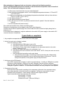
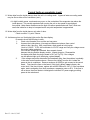
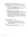
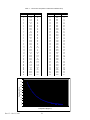
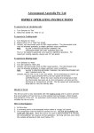
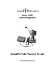
INTRODUCTION The 2013 edition of the Atwood Air Conditioner Service Manual is a resource created to help service technicians identify Atwood products by serial number, diagnose service problems, and efficiently and effectively process warranty claims. This manual offers a general overview of the product as well as more specific product information. For the Air Conditioner product within this manual, you will find model identification, sequence of operation, part identification and troubleshooting guides, warranty procedures, flat rate schedules, and replacement part reference chart. Additional information is available on our website. Visit www.askforatwood.com to download brochures, review trouble shooting guides, and read the latest information bulletins. All Atwood Authorized Service Centers are listed on our site as well, accessible via an easy-to-use search system. Service for all Atwood products is handled out of our Elkhart, IN location. Should you have any questions, please contact service toll-free at 1-866-869-3118, or by e-mail at [email protected]. Please be sure to have the Model and Serial Numbers when you call. Thank you for your business, Atwood Service Team Rev 13 – Oct 11, 2013 1 Atwood AirCommand Air Conditioner Service Manual Table of Contents Recommended Tools and Equipment……………..……………………….……..pg 3 Model Number Identification………..……………………………………….……..pg 3 Air Conditioner Parts (Exploded Views of Ducted and Non-ducted units)...pg 4-7 Service Part Numbers……………………………………………………………….pg 8 Air Conditioner Sequence of Operation………………………………………….pg 9 -10 Thermostat Operation (Lock, Interrogation, Control Parameters)..………...pg 11-14 Troubleshooting Guide (Error Code Test Procedures).…….…………………pg 15-16 Troubleshooting Guide (Typical Fault Conditions).……………………………pg 17-19 Recharging Instructions, Generators and Inverters.……………………..........pg 20 Thermistor Temperature vs Resistance Table..…………………………..........pg 21 Specification Listing..………………………………………..………………..........pg 22 Schematic Diagram …………………………………………………………..….....pg 23 -24 Pictures…………….………………………………………………………………….pg 25-26 Rev 13 – Oct 11, 2013 2 Recommended Tools Common Hand Tools: 1/8” and 1/4” nutdrivers Open end wrenches Flat blade and Philips screwdrivers Packing knife Digital Multimeter Capable of measuring continuity and AC & DC voltages Digital Thermocouple Thermometer Capable of measuring temperature with 2 thermocouples Megohmmeter (megger) Capable of checking for ground leakage paths. Model Number Description AC – 1351 W Color W - White B - Black Generation 1 - First Generation Power rating & Ducted/Non-Ducted 135 – 13.5K BTU; Non- Ducted AC (Air Conditioner) 136 – 13.5K BTU; Ducted AC (Air Conditioner) 150 – 15.0K BTU; Non-Ducted HP (Heat Pump) 151 – 15.0K BTU; Ducted HP (Heat Pump) Appliance Type AC – Air Conditioner Model Number/ Part Number Rev 13 – Oct 11, 2013 Model No Description AC - 1351 W AC - 1501 W AC - 1351 B AC - 1501 B AC - 1361 W AC - 1511 W AC - 1361 B AC - 1511 B Non-ducted Non-ducted Non-ducted Non-ducted Ducted Ducted Ducted Ducted 3 Atwood Part No Roof Unit Only 15025 15026 15030 15031 15027 15028 15032 15033 Exploded View of Air Conditioner Service Parts AC 1361 - DUCTED COOLING Fig # 1 2 3 4 5 6 7 8 9 10 11 12 13 14 15 16 17 18 19 20 21 22 23 24 25 26 27 28 29 30 31 32 33 34 35 36 37 38 39 26 27 28 29 34 39 35 36 Rev 13 – Oct 11, 2013 37 38 4 Description BOLT M6 x 25mm SHROUD CANOPY REINFORCING STRAP RH CANOPY REINFORCING STRAP LH EVAP HOUSING STRAP EVAP HOUSING UPPER EVAP MOTOR STABILIZING BRACKET EVAP HOUSING LOWER EVAP FAN EVAP MOTOR COMPRESSOR STABILIZING BRACKET COMPRESSOR, LG(A), RECHI (B) MOTOR MOUNT BRACKET FAN MOUNTING SUPPORT CONDENSOR FAN MOTOR CONDENSOR FAN CONDENSOR SHROUD CONDENSOR COIL CHARGING TUBE LIQUID LINE AC CHASSIS CONTROL BOX CAPILLIARY ASSEMBLY ROOF SEALING GASKET, HOLE ROOF SEALING GASKET, REAR PLENUM DECK ASSEMBLY HOLD DOWN BARS & BOLTS (incl. DECK ASSY) PLENUM FASCIA SCREWS AND COVER PLUGS (incl. FASCIA) CANOPY SCREWS st4 x 16mm WASHERS inner dia. 6mm FILTER/DRIER EVAP COIL CONTROL BOARD TERMINAL CONNECTOR MOTOR CAPACITOR 10 UF COMPRESSOR CAPACITOR 50 UF CAPACITOR STRAP STANDOFFS Qty 4 1 1 1 1 1 1 1 1 1 1 1 2 2 1 1 1 1 1 2 1 1 1 1 1 1 1 1 1 2 4 2 1 1 1 2 1 1 4 Exploded View of Air Conditioner Service Parts AC 1511 - DUCTED HEAT PUMP Fig # 1 2 3 4 5 6 7 8 9 10 11 12 13 14 15 16 17 18 19 20 21 22 23 24 25 26 27 28 29 30 31 32 33 34 35 36 37 38 39 26 26 27 28 29 34 39 37 35 36 Rev 13 – Oct 11, 2013 38 5 Description BOLT M6 x 25mm SHROUD CANOPY REINFORCING STRAP RH CANOPY REINFORCING STRAP LH EVAP HOUSING STRAP EVAP HOUSING UPPER EVAP MOTOR STABILIZING BRACKET EVAP HOUSING LOWER EVAP FAN EVAP MOTOR COMPRESSOR STABILIZING BRACKET COMPRESSOR, LG MOTOR MOUNT BRACKET FAN MOUNTING SUPPORT CONDENSOR FAN MOTOR CONDENSOR FAN CONDENSOR SHROUD CONDENSOR COIL CHARGING TUBE LIQUID LINE AC CHASSIS CONTROL BOX CAPILLIARY ASSEMBLY ROOF SEALING GASKET, HOLE ROOF SEALING GASKET, REAR PLENUM DECK ASSEMBLY HOLD DOWN BARS & BOLTS (incl. DECK ASSY) PLENUM FASCIA SCREWS AND COVER PLUGS (incl. FASCIA) CANOPY SCREWS st4 x 16mm WASHERS inner dia. 6mm FILTER/DRIER EVAP COIL CONTROL BOARD TERMINAL CONNECTOR MOTOR CAPACITOR 10 UF COMPRESSOR CAPACITOR 50 UF CAPACITOR STRAP STANDOFFS Qty 4 1 1 1 1 1 1 1 1 1 1 1 2 2 1 1 1 1 1 2 1 1 1 1 1 1 1 1 1 2 4 2 1 1 1 2 1 1 4 Exploded View of Air Conditioner Service Parts AC 1351 - NON-DUCTED COOLING # 1 2 3 4 5 6 7 8 9 10 11 12 13 14 15 16 17 18 19 20 21 22 23 24 25 26 27 28 29 30 31 32 33 34 35 36 37 38 39 36 34 39 35 36 Rev 13 – Oct 11, 2013 37 38 6 Description BOLT m6 x 25mm SHROUD CANOPY REINFORCING STRAP RH CANOPY REINFORCING STRAP LH EVAP HOUSING STRAP EVAP HOUSING UPPER EVAP MOTOR STABALIZING BRACKET EVAP HOUSING LOWER EVAP FAN EVAP MOTOR COMPRESSOR STABALIZING BRACKET COMPRESSOR LG (A), RECHI (B) MOTOR MOUNT BRACKET FAN MOUNTING SUPPORT CONDENSOR FAN MOTOR CONDENSOR FAN CONDENSOR SHROUD CONDENSOR COIL CHARGING TUBE LIQUID LINE AC CHASSIS CONTROL BOX CAPILLARY ASSY. ROOF SEALING GASKET, HOLE ROOF SEALING GASKET, REAR DUCT ADAPTER DUCT CEILING PLATE PLENUM CANOPY SCREWS st4 x 16mm WASHERS inner dia. 6mm FILTER/DRIER EVAP COIL CONTROL BOARD TERMINAL CONNECTOR MOTOR CAPACITORS 10UF COMPRESSOR CAPACITOR 50UF CAPACITOR STRAP STANDOFFS Qty 4 1 1 1 1 1 1 1 1 1 1 1 2 2 1 1 1 1 1 1 1 1 1 1 1 1 1 1 1 2 4 2 1 1 1 2 1 1 4 Exploded View of Air Conditioner Service Parts AC 1501 - NON-DUCTED HEAT PUMP # 1 2 3 4 5 6 7 8 9 10 11 12 13 14 15 16 17 18 19 20 21 22 23 24 25 26 27 28 29 30 31 32 33 34 35 36 37 38 39 34 39 37 35 36 38 Rev 13 – Oct 11, 2013 7 Description BOLT m6 x 25mm SHROUD CANOPY REINFORCING STRAP RH CANOPY REINFORCING STRAP LH EVAP HOUSING STRAP EVAP HOUSING UPPER EVAP MOTOR STABALIZING BRACKET EVAP HOUSING LOWER EVAP FAN EVAP MOTOR COMPRESSOR STABALIZING BRACKET COMPRESSOR, LG MOTOR MOUNT BRACKET FAN MOUNTING SUPPORT CONDENSOR FAN MOTOR CONDENSOR FAN CONDENSOR SHROUD CONDENSOR COIL CHARGING TUBE LIQUID LINE AC CHASSIS CONTROL BOX CAPILLARY ASSY. ROOF SEALING GASKET, HOLE ROOF SEALING GASKET, REAR DUCT ADAPTER DUCT CEILING PLATE PLENUM CANOPY SCREWS st4 x 16mm WASHERS inner dia. 6mm FILTER/DRIER EVAP COIL CONTROL BOARD TERMINAL CONNECTOR MOTOR CAPACITORS 10UF COMPRESSOR CAPACITOR 50UF CAPACITOR STRAP STANDOFFS Qty 4 1 1 1 1 1 1 1 1 1 1 1 2 2 1 1 1 1 1 2 1 1 1 1 1 1 1 1 1 2 4 2 1 1 1 2 1 1 4 AC-13X1 AC-15X1 AIR CONDITIONERS HEAT PUMPS SERVICE PARTS Atwood PN Description Picture ID 15000 15015 15016 15021 15022 15023 15024 15025 15026 15027 15028 15029 15030 15031 15032 15033 15034 15050 15051 15054 15055 15056 15057 15060 15061 15062 15064 15066 15070 15071 15072 15073 15077 15078 15079 15080 15081 Literature, IOM Non-ducted AC Plenum Kit, Non-ducted, Off White AC Plenum Kit, Ducted, Off White AC Plenum Kit, Non-ducted, White AC Plenum Kit, Ducted, White AC Remote Control – Non-ducted (no Furnace button) AC 120V Field Connector AC-1351W – Non-ducted, White Roof Unit Only AC-1501W – Non-ducted, White Roof Unit Only AC-1361W – Ducted, White Roof Unit Only AC-1511W – Ducted, White Roof Unit Only AC Wall Thermostat, White – Ducted (with Furnace button) AC-1351B - Non-ducted, Black Roof Unit Only AC-1501B – Non-ducted, Black Roof Unit Only AC-1361B - Ducted, Black Roof Unit Only AC-1511B –Ducted, Black Roof Unit Only AC Wall Thermostat, Black - Ducted (with Furnace button) AC Top Shroud, White AC Top Shroud, Black AC Condenser Fan Motor AC Evaporator Fan Motor AC Condenser Fan AC Evaporator Fan AC Compressor, LG, 15K Only AC Compressor, Rechi, 13.5K Only AC Run Capacitor, Rechi, 13.5K Only AC Run Capacitor, LG, 15K Only AC Inside Filters AC Installation Kit, Hold Down Clamp AC Remote Control – Ducted (with Furnace button) Extender cable, 13ft length (for some ducted units only) Communication cable, 20ft length (for ducted units only) AC Electrical Kit, Non-ducted units Literature, IOM Ducted Control Board, Non-ducted, AC-1351 Control Board, Non-ducted, AC-1501 Control Board, Ducted, AC-1361 and AC-1511 Not shown Not shown Not shown Not shown Not shown Not shown Not shown Not shown Not shown Not shown Not shown Not shown Not shown Not shown Not shown Not shown Not shown 2 2 15 10 16 9 12 12 37 37 32 Not shown Not shown Not shown Not shown Not shown Not shown 34 34 34 Rev 13 – Oct 11, 2013 8 Air Conditioner Sequence of Operation VERIFYING NORMAL OPERATION 1. Turn the power on at the circuit breaker and verify 110VAC between neutral (N) and Line (L). Only on models AC-1501/AC-1511 Figure 2 Refer to the schematic in Figure 2 for steps 2-6. 2. Press the ON/OFF button and press the MODE button to select FAN 3. Cycle through the LO, MED and HIGH fan speeds checking that all speeds run. On HIGH speed – verify that 110VAC is output to the HF terminal with respect to neutral (N). On MED speed – verify that 110VAC is output to the MF terminal with respect to neutral (N). On LOW speed – verify that 110VACis output to the LF terminal with respect to neutral (N). 4. Set mode to COOL, and adjust temperature setting via up/down buttons to approx 6°F (3°C) less than the displayed temperature (ie. room temp). The compressor will start within three minutes. Verify 110VAC on the COMP terminal on the control board. If there is no power on COMP terminal – then check the LIVE terminal on the board as shown in Fig 2. If 110VAC is present then the board may be defective; if not present check AC supply to unit. 5. For heat pump models AC-1501/AC-1511, set mode to HEAT, and adjust the temperature setting to approx. 6°F (3°C) above displayed (room) temperature. The compressor will start within three minutes. Verify 110VAC on the COMP terminal on the control board with respect to neutral (N). Verify 110VAC on the 4WV terminal (to change the refrigerant flow in heat pump mode). Verify 110VAC on one of the fan terminals (based on the fan setting); warm air should be present. 6. For air conditioner models AC-1351/AC-1361, set mode to HEAT, set temp setting to 6°F (3°C) above the displayed (room) temperature. The furnace will start within three minutes. Verify +12VDC on the HTR LIVE terminal (from the furnace) and, when energized, +12VDC should also be on the HTR terminal (going to the furnace) on the control board in Fig 2. Rev 13 – Oct 11, 2013 9 Air Conditioner Sequence of Operation (cont.) 7. A functioning air conditioner should be able to create a temperature difference between the incoming air and the outgoing air. Specifically, in an air conditioner the outgoing air should be 20⁰F-30⁰F (11⁰C-17⁰C) cooler than the incoming air and in a heat pump the outgoing air should be 20⁰F-30⁰F (11⁰C-17⁰C) warmer than the incoming air. Note: Regardless of the mode selected there will always be at least a 3 minute delay before the compressor starts. VERIFYING THERMISTER OPERATION th There are 3 thermistor sensors in an air conditioner and a 4 thermistor sensor in heat pump only applications. 1) Indoor coil sensor - labeled ID on the control board and color coded YELLOW 2) Outdoor coil sensor – labeled OD on the control board and color coded RED 3) Return air sensor – labeled RM on the control board and color coded WHITE 4) Outdoor air sensor – labeled OA on the control board and color coded BLACK (available only on AC-1501/1511) Each thermistor can be verified by measuring its resistance (out of circuit) and comparing the resistance value to the corresponding temperature value listed in the Table 1 near the back of this manual. A detailed troubleshooting method for measuring each thermistor’s resistance is described in detail in the “Error Codes & Troubleshooting” section. In addition, the temperature of each thermistor can be read on the thermostat control assembly by placing the control in the INTERROGATION mode and using TABLE 2 to read each thermistor directly. This is described in detail under the THERMOSTAT OPERATION section and again under E4 of the ERROR CODES & TROUBLESHOOTING section. VERIFYING CONTROL BOARD CONFIGURATION There are 2 jumper locations labeled S1 and S2 on the control board (refer to Fig 2 above). These jumpers allow the control board to be configured for the application. By jumpering pins 1 and 2 on S1, the board is configured as “cooling only”. By jumpering pins 2 and 3 on S1, the board is configured as a “heat pump”. By jumpering pins 1 and 2 on S2, the board is configured with the furnace function off. By jumpering pins 2 and 3, the board is configured with the furnace on. Rev 13 – Oct 11, 2013 10 Thermostat Operation Infra red reception Temperature display area SENSOR To receive wireless handset sign al On/Off button ON/OFF Display timer setting, set or ro om temperature in C or F Room temperature setting button Timer button TEMP Press to activate on/off timer programming mode AUTO HIGH MED LOW TIMER COOL DRY HEAT FAN FAN FURNACE Press once to start operation Press again to stop operation Mode button MODE Press to select cool, dry, heat , fan, or auto operation mode Sleep button SLEEP Press once to select sleep mode Press again to cancel sleep mode Fan speed button Key lock Press to select auto, high, medium or low fan speed Furnace button This button is valid in heatpump + furnace model only Press once to select furnace as primary heating Press again to cancel furnace as primary heating NOTE: Furnace button only available on Ducted Models TEMPERATURE DISPLAY The 2 –digit LED display normally displays the Set Temperature EXCEPT when the SLEEP button is pressed or the control is LOCKED and in the interrogation mode. To display the room temperature, press SLEEP button for 5sec or longer. While this button is depressed, the room temperature is displayed until the key is released. Given the lack of display characters - if the control is displaying temperature in Fahrenheit, temperatures of 100-109°F will be displayed as A0 –A9, temperatures between 110-119°F will be displayed as B0-B9, temperatures between 120-129°F will be displayed as C0-C9, temperatures between 130-139°F will be displayed as D0-D9, temperatures between 140-149°F will be displayed as E0-E9, and temperatures between 150-159°F will be displayed as F0-F9. Temperatures are displayed normally in degrees Centigrade. To change from Centigrade to Fahrenheit display, press the Press the and FAN and FAN buttons together for 5 seconds. buttons together again for 5 seconds to change back from Fahrenheit to Centigrade. LOCK MODE The LOCK mode is provided to prevent unauthorized access to the system settings To enter LOCK mode with the control system on, hold down activate the key lock function, key lock symbol key lock function Rev 13 – Oct 11, 2013 11 and MODE buttons for 3 seconds to will light up. Repeat the same sequence to cancel INTERROGATION MODE To enter the INTERROGATION mode, the control must be in LOCK mode. See above. The INTERROGATION mode allows a person to access the temperature measurements of various sensors throughout the system as well as directly control the air conditioner. ON/OFF o Pressing the o To access the sensors, hold down pushbutton will start or stop the air conditioner. and SLEEP buttons for 1 second to activate sensor temperature display function. The control flashes an LED to identify which sensor’s temperature is being displayed as given in table 2 below. Press or button to select the desired sensor temperature. The displayed temperatures range from 19⁰F to 172⁰F (–9⁰C to 78⁰C). o To exit this mode, hold down the and SLEEP buttons for 1 second to de-activate sensor temperature display function. TABLE 2 – INTERROGATION MODE TABLE No Menu LED Indication Remarks 1 Indoor coil temp Auto fan flashing 2 Outdoor coil temp High fan flashing 3 Outdoor air temp Medium fan flashing 4 Main board room temp Low fan flashing 5 Wall pad room temp Auto and high fan flashing 6 AC voltage supply Auto and medium fan flashing Voltage available shows “AC” else “- -“ 7 Fan control in furnace primary heating Auto and low fan flashing Fan on shows “F0” else “FF“ Rev 13 – Oct 11, 2013 12 CONTROL SYSTEM PARAMETERS This mode allows a person to view and CHANGE the control system parameters. Care must be taken not to change these values unless under strict supervision by a trained Atwood service technician. To display the control system parameters, hold down and FAN buttons for 1 second to activate the system control parameter programming. To select a different parameter to be displayed as listed in TABLE 3 below, press MODE button. To CHANGE a parameter setting press and hold the To exit this mode, hold down FAN and or buttons. buttons for 1 second to de-activate the system control parameter programming. TABLE 3 – CONTROL SYSTEM PARAMETERS No Menu LED Indication Range Remarks 1 Defrost termination temp Auto fan flashing, Sleep off 50⁰F - 59⁰F,default 50⁰F (10⁰C - 15⁰C, default 10⁰C) 2 Heat pump inhibit temp, Thp High fan flashing, Sleep off 32⁰F - 50⁰F,default 44⁰F (0⁰C - 10⁰C, default 7⁰C) 3 Defrost differential, Td Medium fan flashing, 41⁰F - 68⁰F,default 46⁰F Sleep off (5⁰C - 20⁰C, default 8⁰C) 4 Defrost interval TM1 Low fan flashing, Sleep off 68⁰F-302⁰F,default 131⁰F min (20⁰C-150⁰C, default 55⁰C min) Value > 99 is shown in hexadecimal format 5 Defrost interval TM2 Auto and high fan flashing 68⁰F-302⁰F,default 104⁰F min (20⁰C-150⁰C, default 40⁰C min) Value > 99 is shown in hexadecimal format 6 Defrost mode, Dm Auto and medium fan flashing 34⁰F - 36⁰F,default 36⁰F (1⁰C - 2⁰C, default 2⁰C) 1: Outdoor air & coil differential, 2: Coil temperature only. Outdoor air temp to inhibit heat pump operation ERROR CODE DISPLAY Should there be any fault happen with the main board, the relevant error code will be shown on the temperature display area. If there multiple faults happen at the same time, the error codes will be shown one after another. System will alternate the display of error codes and the room temperature. Error codes are listed in the Table 4. Rev 13 – Oct 11, 2013 13 TABLE 4 – ERROR CODES Fault Error code Room sensor failure E1 Indoor coil sensor failure E2 Outdoor coil sensor failure E3 Insufficient of refrigerant E4 Compressor overload E5 Not Used E6 Not Used E7 Outdoor air sensor failure E8 Wall pad room sensor failure E9 INFRARED SIGNAL RECEPTION The system is able to receive the infrared wireless commands from non-LCD handset. MASTER-SLAVE OPERATION It is possible to control the air conditioner in a master-slave relationship if the wall pad is connected to a gateway card. If the master controller is working in global control mode, the key lock LED flashes on the wall pad. None of the button or infra-red reception will be acknowledged until the master controller gives up global control mode. Rev 13 – Oct 11, 2013 14 ERROR CODES & TROUBLESHOOTING E1: Room sensor fault. Action: Usually this is a faulty connection (plug), damaged lead or a faulty sensor. First verify that the White plug is connected to the socket on main board labeled “RM”. Disconnect the White plug and measure the resistance of the thermistor with a digital multimeter as shown in Fig 19. With a thermocouple connected to a digital thermocouple reader, place the thermocouple next to the thermistor sensor to identify the “expected” temperature that thermistor is measuring. Compare the measured resistance value with the expected value in Table 1. If the thermistor is more than 9⁰F (5⁰C) out of calibration then replace the thermistor. When replacing the thermistor, install the cable so that it extends downward from the copper pocket on the coil. E2: Inside coil sensor fault. Usually this is a faulty connection (2 plugs), damaged lead or a faulty sensor. Action: First verify that the Yellow plug is connected to the socket on the main board labeled “ID”. Disconnect the Yellow plug and measure the resistance of the thermistor as outlined in E1 above and replace the thermistor if necessary. Attach the thermocouple to the coil next to the thermistor sensor (ref Fig 22) E3: Outside coil sensor fault. Usually this is a faulty connection (2 plugs), damaged lead or a faulty sensor. Action: First verify that the Red plug is connected to the socket on the main board labeled “OD”. Disconnect the Red plug and measure the resistance of the thermistor as outlined in E1 above and replace the thermistor if necessary. Attach the thermocouple to the coil next to the thermistor sensor (ref Fig 21) WHITE connector in socket labeled RM RED connector in socket labeled OD YELLOW socket labeled ID YELLOW connector from socket labeled ID, resistance of thermistor being measured with multimeter FIG 19 Rev 13 – Oct 11, 2013 15 ERROR CODES & TROUBLESHOOTING (cont): E4: Indicates either a lack of refrigerant, the compressor is not running, or the thermistor is out of calibration. Action: Check that the compressor is running by listening. If it is apparent that the compressor is running, then check the temperature differential across the evaporator by measuring the temperature of the return air at inlet filters and measuring the temperature of the discharge air at the grilles. This temperature differential should be between 25⁰F and 32⁰F (14⁰C and 18⁰C) with the fan set on HI speed. If the temperature differential is less than 25⁰F (14⁰C), the reason could be a lack of refrigerant or a faulty thermistor. Please check the actual thermistor temperature on the coils with the following procedure. Procedure for Measuring Coil Temperatures Using the Control Panel: 1) Set the inside fan to run on HI. 2) While pressing and holding the TEMP DOWN pushbutton, press the MODE pushbutton. 3) Continue pressing both pushbuttons for approximately 5 seconds until the amber LOCK LED illuminates (next to the Key symbol). Release both pushbuttons. 4) Then press and hold both the TEMP DOWN and the SLEEP pushbuttons together for about 1 second until the green MED SPEED LED is flashing. Release both pushbuttons. The display is now reading the temperature of the outside coil. 5) Then press the TEMP UP pushbutton once. This should result in the green HI SPEED LED flashing. The display is now reading the temperature of the inside coil. This temperature will usually be between 41⁰F and 53⁰F (5⁰C and 12⁰C). 6) The temperature differential between the outside and inside coils should be less than 25⁰F (14⁰C). If this temperature differential is 25⁰F (14⁰C) or greater, the thermistor may be out of calibration. Measure the resistance of the thermistor as outlined in E1 above and replace the thermistor if necessary. Note: A temperature differential greater than 43⁰F (24⁰C) can also be caused by a lack of refrigerant. E5: If this message is displayed during the Heating mode, it indicates that the inside coil is too hot. If this message is displayed during the Cooling mode, it indicates that the outside coil is too hot. Action: During cooling, the E5 will appear if the outside coil temperature exceeds 154⁰F (68⁰C). This is an indication that the condenser air flow severely reduced or non-existent. Step 4 in the above procedure describes how to display the temperature of the outside coil. If fans are running and the E5 message is still displayed, verify the thermistor operation as outlined in E3 above. If fans are running and the thermistor is verified, then replace the main control board. E6,E7: These codes are not implemented in this system. If present, then change the main control board E8: This indicates an outdoor air sensor failure. This is usually a faulty connection (2 plugs), damaged lead or a faulty sensor. Action: Measure the resistance of the thermistor as outlined in E1 above and replace the thermistor if necessary. E9: This indicates a wall pad room sensor. Action: Rev 13 – Oct 11, 2013 Replace wall mounted thermostat assembly. 16 When attempting to diagnose a fault over the phone, please ask the following questions. Also it is usually possible to direct the customer to extract thermistor temperature data as described before. This can make fault finding more accurate. 1: Is there now or have there been any error codes displayed? 2: Does the display board appear normal? Are the displayed temperatures between 61⁰F and 86⁰F (16⁰C and 30⁰C)? 3: In heating or cooling modes, can the displayed temperatures be altered via the up /down buttons from 61⁰F to 86⁰F (16⁰C to 30⁰C)? 4: Is the display showing “0”? 5: Is the display showing an unusual figure? 6: When the unit is set to “FAN” only, does the inside fan have 3 speeds? Does the inside fan blow air? 7: Can the compressor be heard running? Error codes are important clues. Refer to preceding pages. Extracting coil temperatures via the display is also vital in many diagnoses. A broken control cable or displaced plug of the control cable will result in either the display being blank or displaying a “0”. If an unusual figure is displayed, it might be attributed to the vehicle’s DC power supply or the vehicle’s DC converter being out of adjustment. Typical faults or complaints 1: Any complaint accompanied with an error code, see earlier pages. 2: Unit will not work and no display is evident. Check the following in order: a. Verify that the main ECB breaker is set to ON b. Verify that AC power is present at the output from the ECB c. Verify that the 4-wire control cable is plugged into the thermostat module in the inside plenum. Reference Fig 23. d. Verify the AC power connection at the underside of unit. e. Verify that the AC fuse is not blown on the main board. NOTE: A faulty fan motor can cause a blown fuse. f. Verify all electrical connections on the main board. a. Verify that the power supply is functioning correctly by checking the voltages at the breakaway plug between the control cable and the display in the plenum. If the DC voltage is not present, a faulty power supply is likely the reason. 3: Unit drops out the ECB breaker: Use a 500V megohmmeter (megger) to check for ground leakage. A reading of 10Megohm or greater indicates no ground leakage; a reading of less than 10Megohm indicates a faulty component. Disconnect each AC load (such as the fan motor, the compressor, etc.), one-by-one until a reading of 10Megohm or greater is obtained. The last load disconnected is the faulty component to be replaced. 4: Compressor will not start: Check that the control board is outputting to the compressor.(yellow wire from compressor relay). Use a clamp ammeter to check for current to compressor. Continuous current above 14 amps indicates a faulty compressor. Check winding continuity with a digital multimeter. Typical measurements for the compressor are as follows: Main Winding: 0.8 ohms Start Winding: 2.1 ohms Resistance to earth: Minimum 20 Meg Rev 13 – Oct 11, 2013 17 Typical faults or complaints (cont) 5: During the cooling mode, the compressor stops. In this fault condition the unit ceases to cool but the display temperatures indicates a very cool value perhaps as low as 50⁰F (10C). This is typical of an inside coil icing up. The thermistor detects that the coil is at or below zero and turns off the compressor until temperature rises to 53⁰F(12⁰C), whereupon the compressor will restart. This situation is usually associated with the unit running for a prolonged period on low fan speed particularly in high humidity conditions. This problem can usually be resolved by running the unit on a higher speed in the “Manual” mode and not using the “Auto” fan setting. Check also that the return air filters are clean. 6: During heating mode, the unit stops heating, fan stops, and the red heat LED blinks. This fault condition indicates that the unit has entered the de-ice mode to rid itself of frost on the outside coils. The unit will restart automatically in 5 to 10 minutes. It should be noted that if the display temp drops to a low figure, on resumption of heating, the blinking red light turns to a steady red light, and the fan will be delayed until the inside coil is warmed to 90⁰F (32⁰C). When the inside fan does start there may be a momentary puff of vapor. This is normal. 7: In very cold conditions the compressor can be heard running but the inside fan does not start. Be patient, in very cold conditions the unit needs time to warm sufficiently to start producing warm air. 8: Compressor transmits excessive vibration. Check that pipe work is not touching other pipes 9: During heating, the unit cycles regularly, the temperature display indicates the room temperature to be between 75⁰F and 82⁰F (24⁰C to 28⁰C) however the average temperature in the cabin is much lower. This condition can be caused by a faulty duct which is causing the warm air to short cycle. To see if this is the cause, disassemble the fascia from the inside plenum (4 screws) and examine carefully the extension duct for leaks, particularly where it joins the horizontal duct. A leaking duct will short cycle warm air onto the return air sensor causing the compressor to close down prematurely. Repair any leaks and reassemble. 10: During cooling, the unit cycles regularly, the temperature display indicates the room temperature to be between 71⁰F and 77⁰F (22⁰C and 25⁰C) however the average temperature in the cabin is much higher. This condition can be caused by a faulty duct which is causing the cold air to short cycle. To see if this is the cause, disassemble the fascia from the inside plenum (4 screws) and examine carefully the extension duct for leaks, particularly where it joins the horizontal duct. A leaking duct will short cycle cold air onto the return air sensor causing the compressor to close down prematurely. Repair any leaks and reassemble. 11: Water drips from the inside plenum when the unit is in cooling mode. Ingress of water on cooling mode may be due to either of four conditions. 1: The unit is installed more than 5 out of level, particularly nose down. 2: The drain holes in the evaporator area are blocked. 3: Condensate that has drained onto the roof, has re-entered the installation hole either under the roof seal of the air conditioner or a roof seam near the unit is faulty. If case 3 appears likely, the unit should be reinstalled using a new sealing gasket and following the Atwood installation instructions explicitly. If there is a roof seam involved, clean the seam area thoroughly and reseal with a silicone sealant compatible with your roofing material. Please Note: If water “pools” around the air conditioner (i.e. the roof has sagged around the air conditioner) then the cabin manufacturer should be consulted. Rev 13 – Oct 11, 2013 18 Typical faults or complaints (cont) 11: Water drips from the inside plenum when the unit is in cooling mode. Ingress of water on cooling mode may be due to either of four conditions (cont.) 4: In high humidity areas, condensate may occur on the underside of the evaporator tray above the inside plenum. This usually associated with running the unit on low speed for a prolonged time period. Under these conditions use the high or medium speeds and avoid “Auto” which can cause the inside fan to drop to low speed as the set point temperature is approached. 12: Water drips from the inside plenum only when it rains. Check condition 11, point 3 above. 13: Unit does not turn on. No display lights on the flip down display. Proceed to check the following in order. 1: Check circuit breaker is on and the van has power. 2: Unscrew the inside plenum (4 screws) and disconnect plenum from control cable via the 4 pin plug. With a multimeter, check power at inlet junction block is 110VAC. If OK, shift multimeter to 12V DC range and verify the voltage across the control cable conductors. If the correct voltages are detected, then suspect a break between this plug and the display module. Inspect plug pins. Disassemble the display and check the plug to board is OK. (ref. Fig 23) If the voltages can be detected right up to the display, replace display. 3: If the voltages cannot be detected at the breakaway plug, then the problem is probably in the main control board enclosure. Remove the canopy from the unit. Isolate the power to the air conditioner. Remove enclosure lid (RHS) to gain access to the control board. First check the fuse on the board. If this fuse is blown it may indicate a fan motor fault. If the fuse is blown, replace with a M205 S/Blow 5A 20 x 5. If the fuse blows again, start investigating for a faulty condenser, evaporator motor or R/V. If the fuse is not an issue, then one needs to investigate the vehicle’s DC power supply providing power to the main board. Rev 13 – Oct 11, 2013 19 Recharging out-of-warranty air conditioners in the field: Occasionally a leak develops in the cooling system which allows refrigerant to escape. If the following 3 conditions are true, then a leak is the most probable reason (assuming that the unit is in cooling mode and the outside temperature is close to 95⁰F (35⁰C) and the inside temperature is 81⁰F (27⁰C): 1: With the inside fan set to HI, the difference in temperature between the inside return air and the discharge air is less than 25⁰F (14⁰C). 2: The inside coil temperature as measured by the thermistor is more than 57⁰F (14⁰C). Refer to E2 fault indicator and corrective action earlier in manual. 3: The suction pressure is less than 58 psi (400 Kpa). Leak Search Process 1. First examine the hermetic system for possible leaks 2. With an electronic leak detector, check all fittings, joints, and tubing. 3. Examine all solder joints. Any leak found in solder joints etc. will require the unit to have any remaining refrigerant recovered, the leak repaired, and the unit evacuated and recharged with 30 oz. (850 grams) of refrigerant. 4. If a leak is detected, at a fitting and the leak has been rectified, refrigerant can be added. Refrigerant should be added until the suction pressure is above 58 psi (400Kpa), the difference between the temperature of the inside return air and the discharge air is greater than 25⁰F (14⁰C) and the inside coil temperature is below 57⁰F (14⁰C). Note: Sometimes all 3 conditions cannot be met so add refrigerant until 2 of the 3 conditions are met. The use of Independent generators or inverters: Failure to start the Air Conditioner: 1: Check that the generator or inverter is rated at 2.8 KW or greater. 2: Check that no other accessories are making a demand on the power load. To check on possible hidden loads, directly wire the air conditioner to the generator or inverter. If unit starts OK then advise the client to identify and isolate the extra electrical load. The display panel has an unusual display of numerals however the unit performs normally on AC power: 1: This is a sign of a poor waveform being generated. Advise client to have generator repaired or replaced with a higher quality unit. Rev 13 – Oct 11, 2013 20 Table 1 - Thermistor Temperature vs Resistance Relationship Temperature Temperature °C °F -10 14 -9 15.8 -8 17.6 -7 19.4 -6 21.2 -5 23 -4 24.8 -3 26.6 -2 28.4 -1 30.2 0 32 1 33.8 2 35.6 3 37.4 4 39.2 5 41 6 42.8 7 44.6 8 46.4 9 48.2 10 50 11 51.8 12 53.6 13 55.4 14 57.2 15 59 16 60.8 17 62.6 18 64.4 19 66.2 20 68 21 69.8 22 71.6 23 73.4 24 75.2 25 77 26 78.8 27 80.6 28 82.4 29 84.2 Resistance kΩ 45 43 41 39 37 36 34 32 31 30 28 27 26 25 24 23 22 21 20 19 18 17.5 17 16 15.5 15 14.3 13.7 13 12.6 12.2 11.7 11.2 10.8 10.4 10 9.6 9.2 8.9 8.6 Temperature Temperature °C °F 30 86 31 87.8 32 89.6 33 91.4 34 93.2 35 95 36 96.8 37 98.6 38 100.4 39 102.2 40 104 41 105.8 42 107.6 43 109.4 44 111.2 45 113 46 114.8 47 116.6 48 118.4 49 120.2 50 122 51 123.8 52 125.6 53 127.4 54 129.2 55 131 56 132.8 57 134.6 58 136.4 59 138.2 60 140 61 141.8 62 143.6 63 145.4 64 147.2 65 149 66 150.8 67 152.6 68 154.4 69 156.2 Resistance kΩ 8.3 8 7.7 7.4 7.1 6.8 6.6 6.4 6.1 5.9 5.7 5.5 5.3 5.2 5 4.8 4.6 4.5 4.4 4.2 4.1 3.9 3.8 3.7 3.6 3.5 3.3 3.25 3.1 3 2.9 2.8 2.75 2.7 2.6 2.5 2.45 2.4 2.3 2.1 50 45 Resistance (kOhm) 40 35 30 25 20 15 10 5 0 -20 -10 0 10 20 30 40 Temperature (Degree C) Rev 13 – Oct 11, 2013 21 50 60 70 80 SPECIFICATIONS Models AC 1351/AC1361 Models AC 1501/AC1511 Electrical rating: Nom. Cooling capacity Input watts cooling Nom. Heating capacity Max. Rated current cooling 115V 60HZ 13500 BTU/H 1400 W -------12.2A 115V 60HZ 15000 BTU/H 1725 W 15000 BTU/H 15A L/R Amps Inside air delivery Installed weight 50.5 A 318 cfm (150 l/s) 84 lbs (38 Kg) 63A 318 cfm (150 l/s) 84 lbs (38 Kg) Overall height Overall width Overall length 13.62 inch (346 mm) 28.15 inch (715 mm) 41.34 inch (1050 mm) 13.62 inch (346 mm) 28.15 inch (715 mm) 41.34 inch (1050 mm) Inside plenum height Inside plenum width Inside plenum length Plenum weight Refrigerant charge 2.56 inch (65 mm) 21.06 inch (535 mm) 21.85 inch (555 mm) 5.29 lbs (2.4 Kg) 18 oz (510 gm) R-410A 2.56 inch (65 mm) 21.06 inch (535 mm) 21.85 inch (555 mm) 5.29 lbs (2.4 Kg) 24 oz (670 gm) R-410A Compressor: Rechi Model: 44A281B Run capacitor 60 uf 250 V LG Model: GKS134CAB Run capacitor 50 uF 250V Fan motor (inside): Solon YYF95-70-4D2 70 watt 1.2 Amps Run Capacitor: 10uf 250 V Solon YYF95-70-4D2 70 watt 1.2 Amps Run Capacitor: 10 uF 250V Fan motor (outside): Solon YYF95-75-4D2 75 watt 1.3 Amps Run Capacitor: 10uf 250 V Solon YYF95-75-4D2 75 watt 1.3 Amps Run Capacitor: 10uF 250V Electronic control board: Exterior power supply Inside electronic Display Saturn type: C115CTTDB0 Saturn 115v / 12v DC Saturn Saturn type: C115CTTDB0 Saturn 115v / 12v DC Saturn Rev 13 – Oct 11, 2013 22 On AC-1511 only Rev 13 – Oct 11, 2013 23 Rev 13 – Oct 11, 2013 24 FIG 20 View of Compressor inside Rooftop Unit Rev 13 – Oct 11, 2013 25 FIG 21 Rev 13 – Oct 11, 2013 FIG 22 26