1
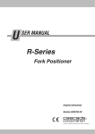
S ERVICE MANUAL G-Series Multiple Pallet Handler Manual Number 6088640-R2 cascade corporation Cascade is a Registered Trademark of Cascade Corporation C ONTENTS Page INTRODUCTION, Section 1 Introduction Special Definitions INSTALLATION, Section 2 Truck System Requirements Recommended Hydraulic Supply Options Installation Procedures PERIODIC MAINTENANCE, Section 3 100-Hour Maintenance 500-Hour Maintenance 1000-Hour Maintenance 2000-Hour Maintenance TROUBLESHOOTING, Section 4 General Procedures Truck System Requirements Tools Required Troubleshooting Chart Plumbing Hosing Diagram Circuit Schematic Fork Position Function Fork Position Circuit Test Sideshift Function Sideshift Circuit Test SERVICE, Section 5 Attachment Removal Forks and Arms Fork Removal Inner Fork Spring Cylinder Service Outer Fork and Arm Removal Outer Arm Bearing Service Inner Fork Carrier Service Fork Tip Alignment Inner Fork Control Service Sideshift Cylinder Cylinder Removal Cylinder Disassembly Cylinder Inspection Cylinder Reassembly Fork Cylinder Cylinder Removal Cylinder Disassembly Cylinder Inspection Cylinder Reassembly Valve Valve Removal Valve Service Base Unit Sideshift Bearing Service SPECIFICATIONS, Section 6 Specifications, Hydraulics Auxiliary Valve Functions Truck Carriage Torque Values i 1 1 2 3 4 9 9 10 10 11 11 11 11 12 12 12 13 13 14 14 15 16 16 16 17 18 19 20 21 22 22 23 23 24 25 25 26 26 27 28 28 29 30 30 31 31 31 31 32 6088640-R2 I 1.1 NTRODUCTION Introduction This manual provides the Installation, Periodic Maintenance, Troubleshooting, Service and Specifications for Cascade G-Series Multiple Load Handlers. These attachments are designed for continuous duty operations with minimal maintenance. They offer exception visibility for the lift truck driver and provide optimized load handling. In any communication about the attachment, refer to the product catalog and serial numbers stamped on the nameplate. If the nameplate is missing, the numbers can be found stamped on the top left side (driver's view) of the frame. IMPORTANT: All hoses, tubes and fittings on these attachments are SAE. NOTE: Specifications are shown in both inch and (Metric) units. All fasteners have a torque value range of ±10% of stated value. Nameplate 25G2-FDS-B221 25G2-FDS-S-00001 SD1126.eps 1 00 1.2 Special Definitions S/N S -FD 25G 00 -S- The statements shown appear throughout this Manual where special emphasis is required. Read all WARNINGS and CAUTIONS before proceeding with any work. Statements labeled IMPORTANT and NOTE are provided as additional information of special significance or to make your job easier. WARNING - A statement preceded by WARNING is information that should be acted upon to prevent bodily injury. A WARNING is always inside a ruled box. CAUTION - A statement preceded by CAUTION is information that should be acted upon to prevent machine damage. IMPORTANT - A statement preceded by IMPORTANT is information that possesses special significance. NOTE - A statement preceded by NOTE is information that is handy to know and may make your job easier. 6088640-R2 1 I 2.1 NSTALLATION Truck System Requirements WARNING: Rated capacity of the truck/ attachment combination is a responsibility of the original truck manufacturer and may be less than that shown on the attachment nameplate. Consult the truck nameplate. Truck Relief Setting 2600 psi (160 bar) Recommended 2900 psi (200 bar) Maximum Truck Flow Volume ➀ Min. ➁ Recommended Max. ➂ 12G FQS 20G–32G FDS 25G–30G FTS 4 GPM (15 L/min.) 7 GPM (26 L/min.) 7 GPM (26 L/min.) 25G FZS 25G–46G FQS 36G–50G FDS 36G–45G FTS 4 GPM (15 L/min.) 10 GPM (37 L/min.) 10 GPM (37 L/min.) ➀ Cascade G-Series Multiple Load Handlers are compatible with SAE 10W petroleum base hydraulic fluid meeting Mil. Spec. MIL-0-5606 or MIL-0-2104B. Use of synthetic or aqueous base hydraulic fluid is not recommended. If fire resistant hydraulic fluid is required, special seals must be used. Contact Cascade. ➁ Flow less than recommended will result in reduced or unequal arm speed. ➂ Flow greater than maximum can result in excessive heating, reduced system performance and short hydraulic system life. GA0400.eps Carriage Mount Dimension (A) ITA (ISO) A Class II Class III Class IV Minimum Maximum 14.94 in. (380.0 mm) 18.68 in. (474.5 mm) 2344 in. (595.5 mm) 15.00 in. (381.0 mm) 18.74 in. (476.0 mm) 23.50 in. (597.0 mm) Carriage Clean carriage bars and inspect for damaged notches. Make sure carriage upper bar is level Auxiliary Valve Functions Check for compliance with ANSI (ISO) standards: Tilt Forward Hoist Down Sideshift Left Open Forks GA0082.eps Hoist Up 2 Tilt Back Close Forks Sideshift Right 6088640-R2 I 2.2 NSTALLATION Recommended Hydraulic Supply Options G-Series Multiple Load Handlers will operate with any of the hydraulic supply arrangements listed below. • All hoses and fittings for FORK POSITION and SIDESHIFT functions should be at least No. 6 with a minimum internal diameter of 7 mm. Refer to Cascade Hose & Cable Reel Selection Guide, Part No. 21299, to select the correct hose reel for the mast and truck. A B C Non-Sideshifting A RH THINLINETM 2-Port Hose Reels OR B LH THINLINETM 2-Port Hose Reels OR C Mast single internal hose reeving Sideshifting A and B RH and LH THINLINETM 2-Port Hose Reels OR C Mast double internal hose reeving GA0033.eps 6088640-R2 3 I 2.3 NSTALLATION Installation Procedures Follow the steps shown to install the Multiple Load Handler on the truck. Read all WARNINGS and CAUTIONS carefully. If you don't understand a procedure, ask your supervisor or call the nearest Cascade Service Department for assistance. 1 Attach overhead hoist A Remove banding. B Set attachment upright on pallet. C If equipped, remove bolt-on lower hooks. WARNING: Check the attachment weight (located on nameplate) to make sure the overhead hoist is at least the rated capacity of the attachment. B B Lower Hooks C SD0623.eps SD0624.eps 2 If equipped, unlock quick disconnect lower mounting hooks A Pull pin from guide. B Rotate hook downward. NOTE: If the hook is jammed, place a screwdriver in the pocket/recess/hole located in the bottom surface of the hook. Hook SD0739.eps B A Guide 4 6088640-R2 I NSTALLATION 3 Mount attachment on truck carriage A Center truck behind the attachment. B Tilt forward and raise carriage into position. C Engage top mounting hooks with carriage. Make B sure center locator tab engages center notch on top carriage bar. D A Lift attachment off pallet. SD0586.eps SD0586.eps ITA Class II – 0.60–0.66 in. (15–17 mm) ITA Class III – 0.72–0.78 in. (18–20 mm) ITA Class IV – 0.72–0.78 in. (18–20 mm) C C C Center Notch ITA Class II – 0.32–0.36 in. (8–9 mm) ITA Class III – 0.39–0.43 in. (10–11 mm) ITA Class IV – 0.47–0.51 in. (12–13 mm) SD0519.eps Truck Carriage 6088640-R2 GA0035.eps Upper Bearings SD0489.eps 5 I NSTALLATION 4 Install and engage lower hooks Lower Carriage Bar Rotate hook up and release pin Pull pin ST JU AD Clearance for sideshifting: .10 in. (2.5 mm) min. .20 in. (5 mm) max. SD0740.eps SD0776.eps Tighten capscrews to a double torque of 165 ft.-lbs. (225 Nm) 5 If required, convert to left hand fork control A Disconnect hoses and label. B Flip valve over. Tighten capscrews to 9 ft-lbs. (12 Nm). C Reconnect hoses as shown. Hose 1 Hose 4 Hose 1 Hose 2 SD0741.eps Hose 4 SD0742.eps Valve RH Hose Layout 6 Hose 3 Hose 3 Valve LH Hose Layout 6088640-R2 I NSTALLATION 6 Prepare hoses A Determine hose lengths required for B CAUTION: Allow extra hose length for sideshift movement of 4 in. (10 cm) in each direction between attachment valve and truck carriage. hydraulic supply configuration of truck. Cut hoses to length, install end fittings or quick-disconnect kits. RH & LH INTERNAL HOSE REEVING Sideshift Right Sideshift Close Forks Left SD0743.eps Open Forks Close Forks Open Forks Sideshift Right Sideshift Left SD0744.eps LH Sideshift, RH Fork Control LH Fork Control, RH Sideshift RH & LH 2-PORT THINLINETM HOSE REELS SD0745.eps 6088640-R2 SD0746.eps 7 I 7 NSTALLATION Flush hydraulic supply hoses A Install hoses using union fittings. B Operate auxiliary valves for 30 sec. C Remove union fittings. 8 Connect hoses to attachment fittings CAUTION: When removing attachment from truck, fully close the forks prior to disconnecting the supply hoses. SD0747.eps GA0092.eps 9 Check attachment functions • With no load, cycle all attachment functions several times. WARNING: Make sure all personnel are clear of the attachment during testing. • Check for operation in accordance with ANSI (ISO) standards. • Lift a maximum load. Sideshift left and right. Check for smoothness and adequate speed. • Check for leaks at fittings, valve, manifold and cylinders FORK POSITION & SIDESHIFT A Sideshift Left B Sideshift Right C Open Forks D Close Forks Tilt Forward Hoist Down A C B B D GA0005.eps Hoist Up Tilt Back C D 8 WARNING: Truck control handle and attachment function activation shown here conforms to ASME/ANSI B56.1 recommended practices. Failure to follow these practices may lead to serious bodily injury or property damage. End user, dealer and OEMs should review any deviation from the practices for safe operation. A C SD0526.eps 6088640-R2 P ERIODIC MAINTENANCE IMPORTANT: Attachment is prelubed at the factory and lubrication is not required for installation. If required, teflon spray or light grease is recommended. WARNING: After completing maintenance procedures, always test the attachment through five complete cycles. First test the attachment empty, then test with a load to make sure the attachment operates correctly before returning it to the job. CAUTION: When removing attachment from the truck, fully close the forks prior to disconnecting the supply hoses. 3.1 100-Hour Maintenance Upper Mounting Hooks Every time the lift truck is serviced or every 100 hours of truck operation, whichever comes first, complete the following maintenance on the attachment: • Check for loose or missing bolts, worn or damaged hoses and hydraulic leaks. • Inspect the cylinder rod anchors for damage. Cylinder anchors operate with a loose clearance and require no lubrication. Cylinder Rod Anchors Upper Sideshift Bearing Grease Fittings • Check for equal movement of the inner and outer forks. 3.2 500-Hour Maintenance After each 500 hours of truck operation, in addition to the 100-hour maintenance, perform the following procedures: • Inspect the inner fork bearings and inner fork rod surface for wear and damage. • Inspect the outer fork arm bars and bearings for wear or damage. If bearing thickness is less than .06 in. (1.5 mm), replace both bearings. • Apply chassis grease to the upper sideshift bearing grease fittings. Sideshift the attachment several cycles to distribute the grease. SD0748.eps Bolt-on Lower Mounting Hook • Apply chassis grease to the lower bearings. Lower the attachment to the ground for access to the bearings. QD Lower Mounting Hook Inner Fork Bearings • Apply chassis grease to the inner fork bearing grease fittings. • Apply Teflon spray or light grease to the inner fork rod surfaces. Lower Bearings Inner Fork Rod Outer Fork Bearings • Apply Teflon spray or light grease to the outer fork arm bar bearing surfaces. • Check the clearance between the lower mounting hooks and the truck carriage bar: QD Hooks – 3/16 in. (4.8 mm) maximum. Bolt-on Hooks – .10 in. (2.5 mm) minimum .20 in. (5 mm) maximum If adjustment is necessary, refer to Installation Step 4. Tighten lower hook capscrews to a double torque of 166 ft.-lbs. (225 Nm). • Inspect the inner fork springs for damage. SD1143.eps Outer Fork Arm Bars 6088640-R2 Inner Fork Springs 9 P 3.3 ERIODIC MAINTENANCE 1000-Hour Maintenance Upper Bearings Upper Bearings After each 1000 hours of truck operation, in addition to the 100 and 500-hour maintenance, perform the following procedures: • Tighten fork capscrews to a double torque of 200 ft.-lbs. (270 Nm). • Inspect the inner fork wear pads for wear. Wear pads worn to flush with the plastic carrier should be replaced. CAUTION: Do not lubricate or paint the lower arm bar front surface that the inner fork wear pads contact. Apply arm bar rust inhibitor (part no. 6145867) to the front surface. • Inspect upper and lower bearings for wear. If any bearing is worn to less than 3/32 in. (2.5 mm) thickness, replace the entire bearing set. See Service Manual for replacement procedure. 3.4 2000-Hour Maintenance After 2000 hours of truck operation, in addition to the 100, 500 and 1000-hour maintenance, forks in use shall be inspected at intervals of not more than 12 months (for single shift operations) or whenever any defect or permanent deformation is detected. Severe applications will require more frequent inspection. Fork inspection shall be carried out by trained personnel to detect any damage that might impair safe use. Any fork that is defective shall be removed from service. Reference ANSI B56.1-2005. Inspect for the following defects: • Surface cracks • Straightness of blade and shank • Fork angle • Difference in height of fork tips • Positioning lock • Wear on fork blade and shank • Wear on fork hooks • Legibility of marking SD1141.eps Lower Bearings Fork Capscrews SD1142.eps Lower Arm Bar − front surface. Do not grease. Inner Fork Wear Pads NOTE: Fork Safety Kit 3014162 contains wear calipers, inspection sheets and safety poster. Also available is fork hook & carriage wear gauge 209560 (Class II), 209561 (Class III) and 6104118 (Class IV). 10 6088640-R2 T ROUBLESHOOTING 4.1 General Procedures 4.1-1 Truck System Requirements • Truck hydraulic pressure should be within the pressure range as shown in Section 6.1. PRESSURE MUST NOT EXCEED 2900 psi (200 bar). • Truck hydraulic flow should be within the volume range as shown in Section 6.1-1. • Truck hydraulic fluid supplied to the attachment must meet the specifications as shown in Section 6.1-1. 4.1-2 Tools Required In addition to a normal selection of hand tools, the following are required: • Inline flow meter: 10 GPM (38 L/Min) – Cascade Part No. 671476 OR 20 GPM (75 L/min) – Cascade Part No. 671477 • Pressure Gauge Kit: 3000 psi (207 bar) – Cascade Part No. 671212 WARNING: Before servicing any hydraulic component, relieve pressure in the system. Turn the truck off and move the truck auxiliary control valves several times in both directions. After completing any service procedure, always test the attachment through several cycles. First test the attachment empty to bleed any air trapped in the system to the truck tank. Then test the attachment with a load to be sure it operates correctly before returning to the job. Stay clear of the load while testing. Do not raise the load more than 10 cm off the floor while testing. Flow Meter Kit 671477 (2) No. 8-12 JIC/ O-Ring Flow Meter GA0013.eps (2) No. 6-8 JIC Reducer • Assorted fittings, lines, drain hoses and quick-couplers as required. Pressure Gauge Kit 671212 Pressure Gauge 4.1-3 No. 6 and No. 8 JIC Swivel Tee No. 6-6 Hose Troubleshooting Chart GA0014.eps Determine All The Facts – It is important to gather all the facts about the problem before beginning any service procedures. The first step is to talk to the equipment operator. Ask for a complete description of the malfunction. Guidelines below can then be used as a starting point to begin troubleshooting: No. 4-6 Pipe/JIC 6088640-R2 No. 4, No. 6 and No. 8 JIC/O-Ring Quick-Coupler Fork Position Circuit • Forks open and close unevenly. • Forks will not open or close. To correct these problems, see Section 4.3. Sideshift Circuit • Attachment will not sideshift. • Attachment sideshifts slowly. To correct these problems, see Section 4.4. No. 6-8 JIC Reducer No. 4 and No. 6 Male Straight or JIC Thread O-ring Coupler No. 6 Female Straight Thread O-ring Coupler AC0127.eps 11 T 4.2 ROUBLESHOOTING Plumbing 4.2-1 Hosing 2-Port Hose Reel OR Internal Reeving Diagram Cylinders Sideshift Cylinder Valve SSR SSL Truck Auxiliary Valves SIDESHIFT LEFT, OPEN FORKS CLOSE OPEN 2-Port Hose Reel OR Internal Reeving PRESSURE RETURN SD0779.eps NOTE: For SIDESHIFT RIGHT, CLOSE FORKS reverse the colors shown. 4.2-2 Circuit Schematic Cylinders Attachment Valve with Crossover Relief Cartridge Attachment Valve Sideshift Cylinder SIDESHIFT Truck Auxiliary Valve Truck Pump OPEN/CLOSE FORKS Truck Auxiliary Valve Truck Relief SD0781.eps 12 6088640-R2 T 4.3 ROUBLESHOOTING Fork Position Function There are six potential problems that could affect the fork positioning function: WARNING: Before removing hydraulic lines or components, relieve pressure in the hydraulic system. With the truck off, open the truck auxiliary control valves several times in both directions. • Incorrect hydraulic pressure or flow from lift truck. • Bent arm bars. • Defective spring cylinders. 2 • External leaks caused by defective cartridge valve or cylinder seals. • Defective inner fork control cylinders. Refer to Section 5.2-7. Flow Meter 4.3-1 Fork Position Circuit Test 1 Check the truck pressure at the carriage hose terminal. Pressure must be within 100 psi (7 bar) of that specified in the truck service manual. TRUCK PRESSURE MUST NOT EXCEED 2900 psi (200 BAR). See Section 6.1 for recommended operating pressure. 2 Check the flow volume at the carriage hose terminal. See Section 6.1-1 for recommended flow volume. 3 Open the forks and check that the inner forks remain in contact with the outer forks until reaching their stops. If they do not, a spring cylinder is faulty. Replace the faulty spring cylinder. Refer to Section 5.2-2. SD0791.eps 4 Fully open and close the forks. If the arms move at different speeds, the flow divider cartridge may be faulty. Replace the cartridge. 5 Fully open and close the forks. 6 Turn the truck off and relieve system pressure. Disconnect the fork positioning bottom cylinder supply hose (base/head end) at the valve. Plug the valve. Place supply hose end into a catch bucket. 7 Start the truck. seconds. Actuate the OPEN FORKS lever for 10 6 Upper cylinder Lower cylinder • If there is substantial hydraulic flow out of the hose, the bottom cylinder is faulty and requires service. Refer to Section 5.4. • If there is no hydraulic flow out of the hose, the upper cylinder may be faulty (see Section 5.4) or the problem is not hydraulic due to bent arms or frame. SD0792.eps Plug Supply hose 6088640-R2 13 T 4.4 ROUBLESHOOTING Sideshift Function WARNING: Before removing hydraulic lines or components, relieve pressure in the hydraulic system. Turn the truck off and open the truck auxiliary control valves several times in both directions. There are four potential problems that could affect the sideshifting function: • Incorrect hydraulic pressure or flow from lift truck. • Lower mounting hooks installed incorrectly. Refer to Section 5.1 Step 5. • Inadequate sideshift upper bearing lubrication or worn bearings. Refer to Section 5.6-1. • External leaks caused by worn or defective cylinder seals. 4.4-1 Sideshift Circuit Test 1 Check the truck pressure at the carriage hose terminal. Pressure must be within 100 psi (17 bar) of that specified in the truck service manual. TRUCK PRESSURE MUST NOT EXCEED 2900 psi (200 Bar). See Section 6.1 for recommended operating pressure. 2 Flow Meter 2 Check the flow volume at the carriage hose terminal. See Section 6.1 for recommended flow volume. 3 Fully retract the sideshift cylinder rod. Hold the lever in the SIDESHIFT LEFT position for a few seconds. Release the lever and check for external leaks at fittings, hoses, valve and manifold. 4 Turn the truck off and relieve system pressure. Disconnect the SIDESHIFT RIGHT supply hose from the sideshift cylinder. Plug the hose end. Install a drain hose from the cylinder fitting to a catch bucket. 5 Start the truck. 10 seconds. 3 Actuate the SIDESHIFT LEFT lever for SD0793.eps • If there is substantial hydraulic flow out of the drain hose, the sideshift cylinder is faulty and requires service. Refer to Section 5.3. • If there is no hydraulic flow out of the hose, the problem is not hydraulic. Refer to Section 4.1-3. SSR Plug Sideshift Cylinder 4 Drain Hose 14 SSL SD0794.eps Back (Driver’s) View 6088640-R2 S 5.1 ERVICE Attachment Removal 2 1 Position the outer forks approximately at the width of the frame. WARNING: Before removing any hoses, relieve pressure in the hydraulic system. Turn the truck off, then actuate the truck control valve several times in both directions. 2 Disconnect the supply hoses from the bulkhead fittings and sideshift cylinder fittings. Tag hoses for reassembly. SD0795.eps 3 Disconnect/remove the lower hooks. Bolt-On Hooks – Remove the lower mounting hooks. For reassembly, tighten capscrews to a double torque of 165 ft.-lbs. (225 Nm). Check clearance for sideshifting leaving a minimum of .10 in. (2.5 mm) space. 4 Quick Change Hooks – Pull out pin and rotate hook down. Release pin. For reassembly, pull pin and rotate hook up. Release pin. 4 Position the attachment over a pallet. Lower the attachment onto the pallet. Tilt the truck carriage forward. Lower carriage and back truck away. 5 For installation, reverse the above procedures except for the following special instructions: • Clean the upper and lower bearings and bearing contact surfaces. • Refer to Section 2 for complete installation instructions. 3 3 Bolt-On Hooks Lower Carriage Bar SD0129.eps Quick Change Hooks Rotate hook up and release pin ST JU AD Pull pin Clearance for sideshifting: .10 in. (2.5 mm) min. .20 in. (5 mm) max. SD0776.eps Tighten capscrews to a double torque of 165 ft.-lbs. (225 Nm) 6088640-R2 SD0740.eps 15 S ERVICE 5.2 Forks and Arms 5.2-1 Fork Removal NOTE: Remove forks one at a time. 3 1 Position outer forks approximately at the width of the frame. 2 Position attachment over a pallet. Lower the attachment onto the pallet. 3 Remove capscrews from fork. For reassembly, tighten the capscrews to a double torque of 200 ft.-lbs. (270 Nm). NOTE: For fork tip alignment, refer to Section 5.2-6. 5.2-2 Inner Fork Spring Cylinder Service SD0584.eps IMPORTANT: Attachment must remain on truck to service spring cylinders. 1 Position forks about (.5 in.) 12 mm above the floor. 2 Open forks about 12 in. (300 mm) to access the inner fork carrier. Remove the spring cylinder rod end nut from the carrier. For reassembly tighten the nut to 39 ft.-lbs. (50 Nm). 3 Fully open forks. 4 Remove the cylinder head/base nut from the frame. For reassembly, tighten the nut to 39 ft.-lbs. (50 Nm). 5 Slide spring cylinders out. 3 4 2 Inner Fork Carrier 16 SD0596.eps 6088640-R2 S 5.2-3 ERVICE Outer Fork and Arm Removal 1 Remove the bolt-on stops from the outer fork arms, using a modified 6 mm allen wrench (Cascade Part No. 6153293). For reassembly, tighten the socket screws to a torque of 24 ft.-lbs. (32 Nm). NOTE: To remove the upper outer fork carrier fork stop, place a 11 in. long, 2 in. x 6 in. board between the forks. Close the forks. Remove the stop capscrews. 2 1 2 Extend the outer forks outside the width of the frame. Position the forks .5 in (12 mm) above the floor. 3 Remove nut from the cylinder rod end. Use Cascade flat wrench, part number 6153275, on the flat of the rod to ease removal of the nut. Support the cylinder with a cable tie. For reassembly, tighten the nut to a torque of 52 ft-lbs. (70 Nm). 4 Attach a suitable overhead hoist around the fork. Pull the fork assembly out of the frame. Cylinder rod extension tool (part number 6151448) can be installed on the cylinder rod to help push the arm out of the frame. 5 Inspect the arm bearings for wear. If the bearings are worn in any area to less than .08 in. (2.0 mm), they should be replaced. For bearing removal, refer to Section 5.2-4. NOTE: Check wear on the outer inside area of the bearings. SD0972.eps Outer Left Carrier Upper Fork Stop 1 4 3 SD0555.eps 6 For reassembly, reverse the above procedures. • Apply arm bar rust inhibitor (Part No. 6145867) to outer arm bars. • Inspect outer lower arm bar for wear. If wear is detected refer to kit 6148830 to install an additional bearing to inner fork carrier hook flange. SD0597.eps 6088640-R2 17 S 5.2-4 ERVICE Outer Arm Bearing Service NOTE: Outer fork arms must be removed to install new bearings. Bearings can be serviced with the attachment on the truck. 1 Remove the bearing retainer plugs using Cascade Tool 6042633 (see illustration). 3 For reassembly, reverse the above procedures with the following exceptions: Install new retainer plugs by using the tool's capscrew to drive the plug in. Bearing retainer plugs are an interference (tight) fit in the frames. Use a small amount of grease to ease installation. NOTE: An M8 x1.25 x 80L capscrew and 40 mm OD fender washer can also be used to remove the retainer plug. 2 Replace the old bearing by tapping a new one into the frame, pushing out the old bearing. The following bearing service kits are available: Model 22G, 25G 28G, 32G Frame Width 47.25 in. (1200 mm) 45.27 in. (1150 mm) Left Arm Bearing Bearing Service Kit Retainer Plug (4) 6073031 6073032 IMPORTANT: Remove the left arm bearings out the left side. Remove the right arm bearings out the right side. Install 2 New Left Arm Bearing Remove Install SD0583.eps 2 New Right Arm Bearing Right Arm Bearing Remove Frame Bearing Retainer Plug Turn nut CW to extract plug Tool 6042633 - Screw in tight 1 REMOVAL Arm Bearings INSTALLATION 3 18 SD0579.eps 6088640-R2 S 5.2-5 ERVICE Inner Fork Carrier Service 1 Position forks about .5 in. (12 mm) off the floor. close forks. Fully WARNING: Do not remove the spring cylinder rod end nut when the forks are completely open. 2 Open outer forks about 12 in. (300 mm) to access the 1 inner fork carrier. The inner forks should not move. 3 Remove the spring cylinder rod end nut from the inner fork carrier. Support the fork spring cylinder with a cable tie. For reassembly, tighten the nut to 37 ft.-lbs. (50 Nm). 4 Completely lower mast carriage. Remove outer fork arms as described in section 5.2-3. 2 5 Remove the capscrew from the pin retainer on the right hand side of the bar. Use a slide hammer (M16) to move the round bar to the left to remove the inner forks. CAUTION: On the left end of the round bar is a keeper pin. Failure to remove the round bar out the left side can damage the grease seals on the inner fork carrier. SD0581.eps 6 Inspect the wear pads for wear. Replace wear pads if the pads are worn flush with the plastic carrier. To remove wear pad, pry out from left or right side. Use a C-clamp and flat plate against the pad to press the new wear pad in place. Keeper Pin 7 For reassembly, reverse the above Slide Hammer procedures except as follows: 5 • Replace inner fork carrier Teflon bearings using a Blind Hole Bearing Puller. • For fork tip alignment, refer to Section 5.2-6. Round Bar 7 5 Teflon Bearings SD0582.eps Inner Fork Carrier 6 Type 1 Wear Pad Type 2 Wear Pad SD0970.eps 6088640-R2 Type 3 Wear Pad SD1144.eps SD0585.eps Shims 19 S 5.2-6 ERVICE Fork Tip Alignment 1 Fully close forks. 2 Measure the vertical offset of the forks 5 in. (125 mm) from the tip of the forks. Outer forks can have a maximum vertical offset of .25 in. (7 mm) above the inner fork. The inner fork must be lower then the outer fork. 3 Fully open forks. 4 Measure the vertical offset of the forks. Outer fork can have a maximum vertical offset of .25 in. (7 mm) above or 0 in. (0 mm) below the inner fork. 5 To align forks, open outer forks so that the inner fork SD0783.eps carrier can be accessed. 6 Lift fork carrier enough to access wear pad. Loosen wear pad and slide shim between wear pad and fork carrier. IMPORTANT: Do not exceed .12 in. (3 mm) of shims in stack. 7 Check vertical offset of outer fork carrier by repeating steps 1 through 4. 2 8 When fork height offset is set within the values above, bend shim tabs to keep in place. + .25 in (7 mm) – 0 in. (0 mm) 3 Type 3 Wear Pad Type 2 Wear Pad SD0970.eps SD1144.eps SD0784.eps Type 1 Wear Pad 4 SD0785.eps Outer Fork .25 in. (7 mm) Inner Fork maximum Outer Fork .0 in. Inner Fork (0 mm) minimum Bend Tabs Lower Inner Fork Carrier 20 6088640-R2 S 5.2-7 ERVICE Inner Fork Control Service 1 Follow steps 1 through 3 in Section 5.2-4. 2 Loosen or remove capscrew in the split collar. For reassembly tighten to a torque of 10 ft.-lbs. (13 Nm). 3 Slide inner fork control group from round bar. 4 Remove the two capscrews from the bracket and cylinder. For reassembly, tighten capscrews to a torque of 10 ft.-lbs. (13 Nm). 5 Remove gas cylinder from the bracket. 6 For reassembly, reverse the above procedures except 1 as follows: • Replace gas cylinder, if needed. • Replace inner fork carrier Teflon bearings. 1 3 SD0622.eps Bracket 4 Gas Cylinder 5 Collar 6088640-R2 2 21 S ERVICE 5.3 Sideshift Cylinder 5.3-1 Cylinder Removal WARNING: Before removing any hoses, relieve pressure in the truck hydraulic system. Turn the truck off, then actuate the truck control valve several times in both directions. 1 Fully retract the sideshift cylinder rod. 2 Disconnect the hoses from the cylinder ports. hoses for reassembly. Tag the 3 Remove the clevis pins from the cylinder ends. the cylinder. Remove 4 For reassembly, reverse the above procedures except for the following special instructions: • Operate the sideshifter through several full cycles to force air in the system to the truck hydraulic tank. Check for leaks at all fittings. SD0796.eps 22 2 3 Clevis Pins 1 6088640-R2 S 5.3-2 ERVICE Cylinder Disassembly 1 Clamp the cylinder in a soft-jawed vise. the extreme base end only. 1 Hose Clamp lightly at 2 Connect a hose to the rod end port. The hose should lead to a catch bucket. Fully extend the cylinder rod. 2 3 Remove the spiral snap ring from the retainer, as shown. 4 Tap the retainer into the shell approximately 2 in. (50 mm). Remove the retaining ring by prying it out of its groove on the opposite side from the split ends. The retaining ring will compress and turn sideways for removal. Remove the retainer. Cylinder Rod CAUTION: Do not scratch the cylinder bore. SS0857.eps 3 To prevent damage to the components and ease of retaining ring removal, use Service Tool Kit 674424. 5 Remove the rod assembly from the cylinder, as shown. 6 To remove the piston, clamp the rod assembly is a vise on the clevis end, as shown. CAUTION: Do not clamp on the cylinder rod sealing surface. 4 7 Remove the piston nut and the piston from the cylinder rod. 5 8 To remove seals, clamp the piston or retainer in a soft-jawed vice. Pry the seals out with a brass seal removal tool (Part No. 674424). Cut the seals. SS0336.eps CAUTION: Do not scratch the seal grooves. 8 6 Piston Retainer SS0061.eps SS0088.eps Restrictor Washer Piston Piston Nut Rod Shell Snap Ring Retaining Ring Retainer SS0858.eps 6088640-R2 23 S 5.3-3 ERVICE Cylinder Inspection 7 Install a new pressure seal and back-up ring on the piston, as shown. • Inspect all components for nicks or burrs. Minor nicks 8 Install the piston on the rod. Tighten the nut to 63 ft.-lbs. or burrs can be removed with 400 grit emery cloth. (85 Nm). NOTE: Minor nicks are those that will not bypass oil 9 Apply a thick film of petroleum jelly to the cylinder under pressure. If nicks cannot be removed with emery shell and piston OD. Install the rod assembly into the cloth, replace the part. cylinder shell. Use a piston/seal loader as required to • Inspect the cylinder bore and remove any minor nicks prevent damage to the seals. or burrs with a butterfly. If they can not be remove, 10 Tap the retainer into the shell far enough to install the replace the parts. circular retaining ring in its groove. • Inspect the outside of the shell for deformities that could weaken the shell’s performance when under pressure. 11 Pull the rod out to fully extended position. Install the Replace if necessary. spiral snap ring on the retainer. 5.3-4 Cylinder Reassembly 1 Polish the piston and retainer chamfer angle with 400 1 grit emery cloth. This allows the seals to slide over the chamfer easier. 2 Wash all components with cleaning solvent. all new seals and rings with petroleum jelly. Piston Lubricate 3 Note the direction of the U-cup seals. If the seals are installed backward they will not work properly. For proper seal placement see the illustration below. 4 Install new pressure seal, wiper seal, O-ring and back-up ring on the retainer, as shown. 5 Clamp piston rod at the clevis end in a soft-jawed vise. CAUTION: Do not clamp on the cylinder rod sealing surface. 6 Apply a thick film of petroleum jelly to the retainer ID and install the retainer on the rod. Use a seal loader as required to prevent damage to seals. SS0063.eps 4 Install new seals. Back-up Ring 3 3 Note seal direction Note seal direction 9 Shell SS0739.eps 24 5 Rod Piston Retainer 6 8 6088640-R2 S 5.4 5.4-1 ERVICE Fork Cylinders 1 Cylinder Removal and Installation NOTE: The following procedures can be performed with the attachment mounted on the truck. 2 1 Fully close the forks. 2 WARNING: Before disconnecting hydraulic lines, relieve pressure in the attachment hydraulic system. Turn the truck off and move the auxiliary control levers several times in both directions. 2 Disconnect the hoses from the cylinder ports. Plug the hoses and cap the cylinder ports. Tag hoses for reassembly. 3 Remove the cylinder rod end nut. 4 Remove the cylinder base/head end nut. Disengage the cylinder from it's mounting boss and lift away from the frame. SD0797.eps 5 For reassembly, reverse the above procedures with the following exceptions: • Tighten cylinder nuts to 52 ft.-lbs. (70 Nm). • Make sure anti-roll pin is installed in cylinder base/ head end. • Cycle forks through five complete cycles to remove air in the cylinders. WARNING: After completing this service procedure, test the forks through five complete cycles. First test empty, then test with a load to make sure the forks operates correctly before returning it to the job. SD0563.eps 3 4 Anti-Roll Pin SD0562.eps 6088640-R2 25 S 5.4-2 ERVICE Cylinder Disassembly 1 1 Clamp the cylinder in a soft-jawed vise at the extreme head end only. Do not clamp on the shell. 2 Unscrew and remove the retainer using a claw-type 2 spanner wrench as shown (Cascade Part No. 678598). 3 Remove the piston/rod assembly from the cylinder. 4 Clamp the piston/rod or retainer in a soft-jawed vise and remove the seals. Piston is a shrink-fit on the rod and not removable. Pry the seals or O-rings up with a brass seal removal tool (Cascade Part No. 674424) and cut the seals to remove them. CAUTION: Do not scratch the seal grooves. Retainer SD0556.eps IMPORTANT: Clamp in Soft-Jawed Vice Only 5.4-3 4 Cylinder Inspection • Inspect the rod, piston and retainer for nicks or burrs. Minor nicks or burrs may be removed with 400 grit emery cloth. If they cannot be removed, replace the parts. • Inspect the cylinder bore and remove any minor nicks or burrs with a butterfly hone. If they cannot be removed, replace the part. • Inspect the outside of the shell for any damage that could impair performance or cause leaks under pressure. If necessary, replace the part. SD0557.eps • Inspect the rod-end anchor nut for wear and replace as necessary. • Inspect anti-roll pin for wear or looseness and replace as necessary. Anti-Roll Pin Piston/Rod Assembly Shell Retainer SD0560.eps 26 6088640-R2 S 5.4-4 ERVICE Cylinder Reassembly 1 Using 400 grit emery cloth, polish the piston and retainer chamfer angles to ease seal installation. Clean all parts thoroughly. 2 Lubricate all new seals and O-rings with petroleum jelly. 3 Install a new seal on the piston. Install the seal from the rod end side of the piston by hooking one side into the groove and carefully working the seal over the piston as shown. Chamfer angle 2 4 6 4 Install the composite wear rings on the piston. 5 Install a new rod seal and wiper seal in the retainer I.D., and a new O-ring and back-up ring on the retainer O.D. as shown. NOTE: Use internal seal installation tool (Cascade Part No. 599512) to ease installation. If installing by hand, form seal into 'kidney' shape and position into internal groove. Use finger pressure to smooth into groove. 6 IMPORTANT: Piston/Rod Assembly SD0558.eps Wear Ring Retainer threads in shell 7 Prior to loading the piston into the shell, assure that no sharp edges exist on the internal threads within the shell. 7 Apply petroleum jelly to the piston and shell threads. Carefully insert the piston into the cylinder shell and using a rubber mallet to drive the piston/rod assembly into the shell. 8 Apply petroleum jelly to the retainer I.D. and slide onto the rod. Screw the retainer into the shell. Use a claw-type spanner wrench, tighten the retainer to 125 ft.-lbs. (170 Nm). 9 Make sure anti-rotation pin fits tightly in place at Retainer 8 SD0559.eps cylinder head end. Replace if necessary (pin size: M5 x 12). Wiper Seal Rod Seal 9 Piston Anti-Rotation Pin 6 Piston/Rod Assembly 5 Note seal direction SD0561.eps Wear Ring 3 6088640-R2 Wear Ring Two-Piece Seal O-Ring Backup Ring Cylinder Retainer 27 S ERVICE 5.5 Valve 5.5-1 Valve Removal 1 Remove attachment as described in Section 5.1. WARNING: Before removing any hoses, relieve pressure in the hydraulic system. Turn the truck off, then actuate the truck control valve several times in both directions. 2 Disconnect the hoses from the valve ports. hoses and tag them for reassembly. Plug the 3 Remove the capscrews fastening the valve to the frame. For reassembly, tighten the capscrews to a torque of 10 ft.-lbs. (13 Nm). 4 For reassembly, reverse the above procedures. RH HOSE LAYOUT SD0847.eps 28 2 3 2 LH HOSE LAYOUT SD0848.eps 2 3 2 6088640-R2 S 5.5-2 ERVICE Valve Service 1 Remove the cartridge from the valve. 2 Remove the remaining fittings. 3 Remove the O-rings and back-up rings from the cartridge. 4 Clean all parts with cleaning solvent. 5 For reassembly, reverse the above procedures except for the following special instructions: • The cartridge O-rings and back-up rings must be installed as shown for proper hydraulic operation. Single Cartridge Valve 1 Flow Divider Cartridge 2 • Lubricate the cartridges and seals with petroleum jelly prior to reassembly. 2 Flow Divider Cartridge Fitting Valve O-Rings SD0799.eps 210266 6034595 DFD Deltrol Two Cartridge Valve 1 CL0341.eps Back-up Rings 1 Flow Divider Cartridge Crossover Relief Cartridge 2 Crossover Relief Cartridge O-Rings 2 Fitting Valve CL2850.eps Back-up Rings SD0800.eps 6088640-R2 29 S ERVICE 5.6 Base Unit 5.6-1 Sideshift Bearing Service 1 Remove attachment from the truck as described in Section 5.1 2 Remove clevis pin from head/base end of the Sideshift cylinder. 3 Inspect the upper bearing thickness. If either one is worn less then .06 in. (1.5 mm) thick on the back surface, replace both bearings. 4 Inspect the lower bearing exposed thickness. If the exposed thickness is less than .06 in. (1.5 mm), replace both bearings. 5 For reassembly, reverse the above procedures except for the following instructions: • Clean the upper and lower bearings and bearing surfaces. • Locate the upper bearings in the anchor bracket cutouts. Be careful not to install the bearings backwards. • Check the upper mounting hook capscrew torque. Double torque to 166 ft.-lbs. (225 Nm). 2 3 Upper Bearing .06 in. (1.5 mm) minimum Upper Bearing SD0590.eps 30 4 6088640-R2 S PECIFICATIONS 6.1 Specifications 6.1-1 Hydraulics Truck Relief Setting 2600 psi (160 bar) Recommended 2900 psi (200 bar) Maximum Truck Flow Volume ➀ Min. ➁ Recommended Max. ➂ 12G FQS 20G–32G FDS 25G–30G FTS 4 GPM (15 L/min.) 7 GPM (26 L/min.) 7 GPM (26 L/min.) 25G FZS 25G–46G FQS 36G–50G FDS 36G–45G FTS 4 GPM (15 L/min.) 10 GPM (37 L/min.) 10 GPM (37 L/min.) ➀ Cascade G-Series Multiple Load Handlers are compatible with SAE 10W petroleum base hydraulic fluid meeting Mil. Spec. MIL-0-5606 or MIL-0-2104B. Use of synthetic or aqueous base hydraulic fluid is not recommended. If fire resistant hydraulic fluid is required, special seals must be used. Contact Cascade. ➁ Flow less than recommended will result in reduced or unequal arm speed. ➂ Flow greater than maximum can result in excessive heating, reduced system performance and short hydraulic system life. GA0397.eps Hoses and Fittings All supply hoses must be at least No. 6 minimum All fittings must have an orifice size of 9/32 in. (7 mm) minimum. 6.1-2 Auxiliary Valve Functions Check for compliance with ANSI (ISO) standards. TIlt Forward Hoist Down Sideshift Left Open Forks GA0082.eps Hoist Up 6088640-R2 Tilt Back Sideshift Right Close Forks 31 S 6.1-3 PECIFICATIONS Truck Carriage Carriage Mount Dimension (A) ITA (ISO) A Class II Class III Class IV Minimum Maximum 14.94 in. (380.0 mm) 18.68 in. (474.5 mm) 2344 in. (595.5 mm) 15.00 in. (381.0 mm) 18.74 in. (476.0 mm) 23.50 in. (597.0 mm) GA0389.eps 32 6088640-R2 S 6.1-4 PECIFICATIONS Torque Values NOTE: All fasteners have a torque value range of ±10% of stated value. Fastener torque values for the G-Series Multiple Load Handler are shown in the table below in both U.S. and Metric units. Torque values are also found in each specific service procedure section throughout the manual. Ref. Fastener(s) Size Ft.-lbs. Nm 1 2 3 4 5 6 7 8 9 10 11 Cylinder Nuts M20 52 70 Retainer Capscrews M16 48 65 Spring Cylinder Nuts M14 37 50 Fork Stop Capscrews ▲ M8 24 32 Fork Capscrews M16 200 270 Fork Stop Spacer Capscrews M8 14 19 Sidesifter Spacer Capscrews ▲ M10 28 38 Mounting Hook Capscrews ▲ M16 166 225 Sideshifter Plate Capscrews M6 6 8 Valve Capscrews M6 10 13 Lower Hook Capscrews ▲ M16 166 225 12 Quick-Disconnect Lower Hook Capscrews ▲ M16 166 225 1 2 3 4 ▲ Double torque SD0591.eps 5 6 7 8 9 Class II Only SD0592.eps 12 6088640-R2 SD0801.eps 10 11 33 Do you have questions you need answered right now? Call your nearest Cascade Service Department. Visit us online at www.cascorp.com AMERICAS Cascade Corporation U.S. Headquarters 2201 NE 201st Fairview, OR 97024-9718 Tel: 800-CASCADE (227-2233) Fax: 888-329-8207 Cascade Canada Inc. 5570 Timberlea Blvd. Mississauga, Ontario Canada L4W-4M6 Tel: 905-629-7777 Fax: 905-629-7785 Cascade do Brasil Rua João Guerra, 134 Macuco, Santos - SP Brasil 11015-130 Tel: 55-13-2105-8800 Fax: 55-13-2105-8899 EUROPE-AFRICA Cascade Italia S.R.L. European Headquarters Via Dell’Artigianato 1 37030 Vago di Lavagno (VR) Italy Tel: 39-045-8989111 Fax: 39-045-8989160 Cascade (Africa) Pty. Ltd. PO Box 625, Isando 1600 60A Steel Road Sparton, Kempton Park South Africa Tel: 27-11-975-9240 Fax: 27-11-394-1147 ASIA-PACIFIC Cascade Japan Ltd. 2-23, 2-Chome, Kukuchi Nishimachi Amagasaki, Hyogo Japan, 661-0978 Tel: 81-6-6420-9771 Fax: 81-6-6420-9777 Cascade Korea 121B 9L Namdong Ind. Complex, 691-8 Gojan-Dong Namdong-Ku Inchon, Korea Tel: +82-32-821-2051 Fax: +82-32-821-2055 Cascade-Xiamen No. 668 Yangguang Rd. Xinyang Industrial Zone Haicang, Xiamen City Fujian Province P.R. China 361026 Tel: 86-592-651-2500 Fax: 86-592-651-2571 Cascade Australia Pty. Ltd. 1445 Ipswich Road Rocklea, QLD 4107 Australia Tel: 1-800-227-223 Fax: +61 7 3373-7333 Cascade New Zealand 15 Ra Ora Drive East Tamaki, Auckland New Zealand Tel: +64-9-273-9136 Fax: +64-9-273-9137 Sunstream Industries Pte. Ltd. 18 Tuas South Street 5 Singapore 637796 Tel: +65-6795-7555 Fax: +65-6863-1368 Cascade India Material Handling Private Limited No 34, Global Trade Centre 1/1 Rambaugh Colony Lal Bahadur Shastri Road, Navi Peth, Pune 411 030 (Maharashtra) India Phone: +91 020 2432 5490 Fax: +91 020 2433 0881 c Cascade Corporation 2011 10-2011 Part Number 6088640-R2