1
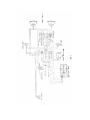
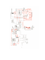
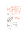
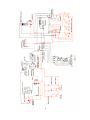
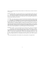
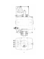
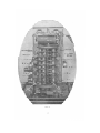
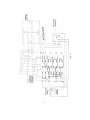
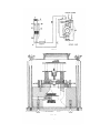
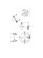
INSTRUCTIONS
FOR THE CARE OF
6-24
Delco Systems
The Dayton Engineering Laboratories Co.
Dayton, Ohio
This is a description of the 6-24 volt system as applied to the following cars:
1912 Cadillac
1913 Cole
Models
4-40,
4-50,
6-60
1913 Hudson
"
37,
54,
1913 Oakland
"
42,
6-60,
1913 Oldsmobile
"
53,
DESCRIPTION - The principal units of the system are: a two-pole motor generator with a single
armature winding, which generates at 6 volts and cranks at 24 volts; a storage battery consisting
of four groups of three cells each, connected to a controller in such a way as to permit of series or
parallel grouping a dual ignition system using current from the generator and also providing for
ignition from the dry cells. The system is ungrounded. The lamps used are 6-volt lamps.
OPERATION - Figures 1 and 2 cover the typical wiring and circuit diagrams of this system, from
which its general characteristics can be obtained. The following cycle of operations is necessary
when starting the car with this apparatus. First, the ignition switch button marked "start" is pressed
(see Figure 16), which puts the ignition system on the dry cells and gives a vibrating spark. When
the starting button is depressed, it closes the circuit around the cut-out relay and through the
magnetic latch coil, operating the motor generator as a 6-volt series motor. This causes the
armature of the motor generator to revolve at slow speed. The circuits used during the operation
of motoring to mesh the gears, are shown in red on the circuit diagram in Fig. 3. With the system
in operation as mentioned above, the clutch pedal is pressed down, the gears are meshed and the
controller thrown over to the 24-volt side, connecting the series windings of the motor generator
directly to the 24-volt battery. As the gears between the motor pinion and the teeth on the flywheel
are now meshed, connecting the flywheel directly with the armature of the motor generator, the
latter will crank the engine, and at a speed approximately 20 to 30 revolutions per minute. The
circuits used during the cranking operation are shown in red in the circuit diagram, Fig. 4. It should
be noted particularly that during the cranking operation, the armature of the motor generator is
revolving at approximately 20 times engine, speed and therefore is slipping the driving clutch on
the front end. Now, when the engine picks up and fires, during the instant that the gears are still in
mesh and the engine is running faster than the armature of the motor generator, the starting clutch
will be slipping and the driving clutch taking hold. These points should be kept in mind, as they
explain the reason for the presence of such clutches in this apparatus, and are necessary to a clear
understanding of the operation of the motor generator.
When the engine picks up and passes a certain speed, the generator produces a sufficient voltage
to close the cut-out relay and then begins to charge the storage battery. The charging circuit is
outlined in red in Fig. 5. The lighting and ignition circuits are outlined in red
2
in Fig. 6, so that they may be kept clearly in mind, if it is. Desired to trace out these circuits for
testing purposes.
MOTOR GENERATORS - The motor generators are of two general designs, both two-pole, the
first being a box type machine with two field coils and the second a single coil machine.
Figs. 7 and 8 show these machines in section and give a good idea of their general construction.
So far as the mechanical construction goes, little need be said, except that all of them have a
driving clutch mounted on the front end.
CLUTCHES - The driving clutches are keyed to the shaft with a Woodruff key and then pinned
in position with a round pin held with a set-screw in the front end of the armature shaft.
For starting purposes, a set of sliding gears, in which is incorporated a starting clutch, meshes with
the motor pinion and the teeth of the flywheel. Fig. 9 shows, the construction of the clutch. In
making adjustments or checking installations, it should be noted that the teeth of the stub gear
which mesh with the flywheel teeth should clear the flywheel by approximately 1/8 inch, when the
motor pinion has just begun to mesh with the ring gear of the starting clutch. In the case of some
of these generators, the starting gears are mounted in the rear housing of the motor generator; in
others, they are mounted separately in a special housing bolted to the flywheel housing.
MAGNETIC LATCH - On the cars using this system, the little catch operated by the magnetic
latch engages with the clutch pedal to operate the controller, which changes over the battery connections to the series connection during the cranking operation. The connections for the
magnetic latch are shown in red on the circuit diagram, Fig. 3. The motor is operated as, a series
motor on a 6-volt circuit, as mentioned above, with the coil of the magnetic latch in series with
the motor. When the clutch pedal is pressed down, it forces the blades of the controller over from
the left to the right-hand side, thus connecting the cells of the battery in series. This is done by a
link
work connecting the handle of the controller to the catch operated by the magnetic latch.
9
CONTROLLER - Fig. 10 shows a front view of the controller and the general
arrangement of its blades. Fig. 11 gives a circuit diagram of the
controller, including its connections, to the storage battery, ampere hour meter and
meter contacts. The meter contacts are connected into the circuit at " C " and " D " (Fig.
11) and are shown in greater detail in Fig. 12. They are designed to either insert
resistance in the shunt field of the generator when the battery is charged to a certain
extent, thus reducing the charging rate and preventing overcharge of the battery, or to
open the field circuit entirely, for a similar purpose. These contacts are operated by the
large hand on the ampere hour meter. Their adjustment simply requires that they make
good contact and with sufficient pressure between them; in other words, that the
contacts be clean and flat and that the blades on which they are mounted shall not have
lost their temper. If for any reason they are found in such a condition that their repair
does not seem warranted, they should be short circuited by connecting the No. 1 and 2
battery box terminals together permanently with a heavy copper wire. This will cut the
meter contacts out of the circuit entirely. At the same time this is done, it will be well
to shorten the large meter hand or remove it entirely to prevent a possible ground
developing at this point. After cleaning the controller blades, it is necessary to keep
them oiled slightly with a light cylinder oil.
CUT-OUT RELAY-The adjustment of the cut-out relay has been covered in another
article, describing it in detail. This can be had on application.
12
AMPERE-HOUR METER - The ampere-hour meter is of the mercury motor type, a
section of which is shown in Fig. 13, and is connected into
the circuit at the points lettered "A" and "B" in the diagram of the controller shown in
Fig. 11, and to the controller itself at No. 3 battery box terminal and at " G, " so that by
connecting a heavy copper wire between these points, the meter can be removed for
repairs. The little porcelain resistance spool, mounted on its base, is used in connection
with the meter contact and has nothing to do whatever with the operation of the meter
itself.
The meter consists of a disc of copper, floating in a well of mercury and mounted
in the magnetic field formed by two or more sets of permanent magnets. The lines of
force cut the copper disc at two points. The mercury has about 40 times the resistance
of the copper disc, and hence the bulk of current passing through the meter will pass
through the disc and approximately in a diametral line. The reaction between the
magnetic field, formed by the current passing through the disc in this manner, and the
field formed by the permanent magnets, will cause the disc to revolve and at a speed
roughly proportional to the current A shunt is placed across the terminals, and by this
means it is possible to calibrate the meter.
CHARGING SHUNT - The charging rate on these motor generators is adjusted by
varying the resistance of the charging shunt Figures. 10 and 14).
These shunts come in two sizes, single and double strand. For fast driving the single
strand shunt is to be recommended; for slow driving, the double strand. If the shunts
burn out, they should not be replaced by copper wire, as the charging rate will then
be excessive. The shunt simply divides the charging current with the series field,
which is in a reverse direction to the shunt field, and therefore supplies the regulation
for this motor generator. If it is shorted out of the circuit entirely, as it will be if a
copper charging shunt is placed between the two upper left-hand controller blades, the
charging rate will rise to an excessive value, due to the lack of sufficient regulation. If
the shunt burns out frequently, or in a very short time, it will tend to indicate that there
is a high terminal voltage across the field series, which, in turn, will be caused by poor
connections some-where in the generator circuit. When this occurs, therefore, all the
terminals in the system, including particularly the battery terminals, the terminals on
the motor generator and on the battery box, should be gone over and cleaned and
tightened, if found to require this attention. The wires at any junction box should be
inspected to make sure
16
that the connections have not become loose. The controller blades also should
be tested to make sure that they are making good contact. By going over the
system in this way, it is possible to eliminate such trouble permanently.
OVERHAULING - With regard to overhauling the motor generator, this
should be done about once a year, so that the old grease
can be cleaned out and replaced by fresh grease, the parts cleaned, the mica on
the commutator undercut, if it is high, and the brushes replaced or refitted, if
necessary. For details of work on the commutator and brushes, refer to articles
on these subjects which can be had on application.
GROUNDS - It has been found in a number of cases where grounds have
developed in these systems, interfering with the ignition, that
they are caused by grounds in the special apparatus which has been added to
the system since they were produced, such as extra lights or electric horns of
one type or another, and it will be well, where ignition trouble indicates
grounds in the system, to disconnect such special apparatus and see if the
grounds are not located at this point.
CHARGING RATE - When it is desired to test the charging rate of the
generator, an ammeter of 30 ampere capacity should
be inserted in the line between the generator and the cut-out relay, referring to
Fig. 11. This is most easily done by disconnecting the lead going to the outside
of the two main terminals of the Cut-Out Relay, lettered No. 1 in the figure,
and attaching it to one terminal of the ammeter; then attach the other terminal
of the ammeter by a piece of copper wire, to the No. 1 terminal of the cut-out
relay.
In these systems the charging rate should be approximately 22 amperes as
a maximum, although a slight variation either way is permissible to care of the
peculiar conditions of driving.
17
18
IGNITION - The ignition calls far little attention outside of the usual care
given such systems. The resistance unit is shown in Fig. 15.
The timing is accomplished -by raising the distributor gear and setting it a
tooth ahead or a tooth behind. In regard to the exact method of timing, it
might be stated that all of the cars using this system are timed so as to permit
1/3 retard and 2/3 advance on the quadrant. In other words, the motor
should be timed so that the "mag." contacts are just beginning to break with
the engine on No. 1 dead center and the spark lever advanced 1/3 of the way
on the quadrant. The ignition switch is shown in Fig. 16, and will be found
to give very little trouble indeed. If it is necessary or desirable to test it, a
piece of copper wire can be bridged across the terminals used and thus
readily show whether or not the contacts specified are giving trouble, due
to grit or insufficient pressure between them.
If the ignition system is giving trouble of any kind, reference should be
made to an article on ignition which covers this subject very completely.
Likewise, if it is desired to adjust the ignition relay, reference should be
made to a special article in the service Manual on that subject. These articles
may be had on application.
LUBRICATION - The oiling of the apparatus is a comparatively simple
operation. Oil holes are provided for oiling the ball
bearings at the front and rear of the motor generator. A grease cup is
supplied to lubricate the starting clutch and the shaft on which the starting
gears slide and by repacking the driving clutch with grease whenever it
becomes dried out, and seeing that the distributor gears are kept properly
lubricated and the bottom and top cone ball bearings of the distributor are
getting lubricated with a few drops of oil, little trouble should be experienced, due to excessive wear and lack of lubrication.
Form 193 Delco - 4-6-20 - 6M - J. W. P.
19