1
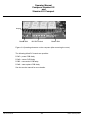
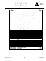
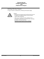
Raytheon Anschütz GmbH Postfach 1166 D -- 24100 Kiel Germany Tel +49--4 31--30 19--0 Fax +49--4 31--30 19--501 Email [email protected] www.raytheon--anschuetz.de Standard 22 Compact GYRO COMPASS and Standard 22 GYRO COMPASS Type 110 --233 NG002 E01/E02 Operator manual 4201.DOC010102 Edition: February 2015 Weitergabe sowie Vervielfältigung dieser Unterlage, Verwertung und Mitteilung ihres Inhaltes nicht gestattet, soweit nicht ausdrücklich zugestanden. Zuwiderhandlungen verpflichten zu Schadenersatz. Copying of this document, and giving it to others and the use or communication of the contents thereof, are forbidden without express authority. Offenders are liable to the payment of damages. Toute communication ou reproduction de ce document, toute exploitation ou communication de son contenu sont interdites, sauf autorisation expresse. Tout manquement à cette règle est illicite et expose son auteur au versement de dommages et intérêts. Sin nuestra expresa autorización, queda terminantemente prohibida la reproducción total o parcial de este documento, así como su uso indebido y/o su exhibición o comunicación a terceros. De los infractores se exigirá el correspondiente resarcimiento de daños y perjuicios. Operator manual Compass Standard 22 and Standard 22 Compact Compass Standard 22 TABLE OF CONTENTS Page 1 General . . . . . . . . . . . . . . . . . . . . . . . . . . . . . . . . . . . . . . . . . . . . . . . . . . . . . . . . . . . . . . . . . . 1 1.1 STD 22 Compact Gyro Compass . . . . . . . . . . . . . . . . . . . . . . . . . . . . . . . . . . . . . . . . . . . . 3 1.1.1 1.1.2 STD 22 Compact Gyro Compass -- Scope of Supply . . . . . . . . . . . . . . . . . . . . . . . . . . . STD 22 Compact Gyro Compass optional features . . . . . . . . . . . . . . . . . . . . . . . . . . . . 5 6 1.1.2.1 Quick Settling operator unit . . . . . . . . . . . . . . . . . . . . . . . . . . . . . . . . . . . . . . . . . . . . . . . . . 6 1.1.2.2 AC/DC converter, 121-062 . . . . . . . . . . . . . . . . . . . . . . . . . . . . . . . . . . . . . . . . . . . . . . . . . . 7 1.1.2.3 Additional Output Box 146--103 . . . . . . . . . . . . . . . . . . . . . . . . . . . . . . . . . . . . . . . . . . . . . 7 1.2 STD 22 Gyro Compass . . . . . . . . . . . . . . . . . . . . . . . . . . . . . . . . . . . . . . . . . . . . . . . . . . . . 8 1.2.1 STD 22 Gyro Compass -- Scope of Supply . . . . . . . . . . . . . . . . . . . . . . . . . . . . . . . . . . . . 11 1.2.2 1.2.2.1 Optional features for the STD 22 Gyro Compass . . . . . . . . . . . . . . . . . . . . . . . . . . . . . . AC/DC converter, 121-062 . . . . . . . . . . . . . . . . . . . . . . . . . . . . . . . . . . . . . . . . . . . . . . . . . . 12 12 1.3 Technical data . . . . . . . . . . . . . . . . . . . . . . . . . . . . . . . . . . . . . . . . . . . . . . . . . . . . . . . . . . . . 13 1.3.1 1.3.2 Mechanical data . . . . . . . . . . . . . . . . . . . . . . . . . . . . . . . . . . . . . . . . . . . . . . . . . . . . . . . . . . . Electrical data . . . . . . . . . . . . . . . . . . . . . . . . . . . . . . . . . . . . . . . . . . . . . . . . . . . . . . . . . . . . . 13 13 1.3.3 General Technical Data . . . . . . . . . . . . . . . . . . . . . . . . . . . . . . . . . . . . . . . . . . . . . . . . . . . . 14 2 2.1 Controls and Indicators on the Gyro Compass . . . . . . . . . . . . . . . . . . . . . . . . . . . . . . . . Switching on the STD 22 Compass . . . . . . . . . . . . . . . . . . . . . . . . . . . . . . . . . . . . . . . . . . 15 17 2.1.1 Indications on the compass during the heating stage . . . . . . . . . . . . . . . . . . . . . . . . . . . 18 2.1.2 Indications on the compass during the settling stage . . . . . . . . . . . . . . . . . . . . . . . . . . . 19 2.1.3 Overview of indications (digital display) during operation . . . . . . . . . . . . . . . . . . . . . . . . 20 2.2 Heading correction . . . . . . . . . . . . . . . . . . . . . . . . . . . . . . . . . . . . . . . . . . . . . . . . . . . . . . . . 21 2.2.1 2.2.1.1 Alignment error . . . . . . . . . . . . . . . . . . . . . . . . . . . . . . . . . . . . . . . . . . . . . . . . . . . . . . . . . . . Procedure for setting the compass zero (A-error) . . . . . . . . . . . . . . . . . . . . . . . . . . . . . . 21 22 2.2.2 Speed error . . . . . . . . . . . . . . . . . . . . . . . . . . . . . . . . . . . . . . . . . . . . . . . . . . . . . . . . . . . . . . . 24 2.2.2.1 Speed error table . . . . . . . . . . . . . . . . . . . . . . . . . . . . . . . . . . . . . . . . . . . . . . . . . . . . . . . . . . 26 3 Operating conditions requiring attention . . . . . . . . . . . . . . . . . . . . . . . . . . . . . . . . . . . . . . 30 3.1 Operating conditions requiring attention, their causes, and what to do . . . . . . . . . . . . 31 3.1.1 3.1.2 Operating condition 1 “Fan failure” . . . . . . . . . . . . . . . . . . . . . . . . . . . . . . . . . . . . . . . . . . . Operating condition 2 “Heater failure” . . . . . . . . . . . . . . . . . . . . . . . . . . . . . . . . . . . . . . . . 33 34 3.1.3 Operating condition 3 “Supporting liquid > 60C.” . . . . . . . . . . . . . . . . . . . . . . . . . . . . . . 34 3.1.4 Operating condition 4 “Supporting liquid level too low” and its immediate measure . . . . . . . . . . . . . . . . . . . . . . . . . . . . . . . . . . . . . . . . . . . . . . . . . . . . . . . . . . . . . . . . . 35 3.1.4.1 With switching off the gyro compass . . . . . . . . . . . . . . . . . . . . . . . . . . . . . . . . . . . . . . . . . 35 3.1.4.2 3.1.5 Without switching off the gyro compass . . . . . . . . . . . . . . . . . . . . . . . . . . . . . . . . . . . . . . Operating condition “Voltage cut-off” . . . . . . . . . . . . . . . . . . . . . . . . . . . . . . . . . . . . . . . . . 39 42 4 Alert signalling . . . . . . . . . . . . . . . . . . . . . . . . . . . . . . . . . . . . . . . . . . . . . . . . . . . . . . . . . . . . 43 5 Switching off the Gyro Compass . . . . . . . . . . . . . . . . . . . . . . . . . . . . . . . . . . . . . . . . . . . . . 46 6 Maintenance . . . . . . . . . . . . . . . . . . . . . . . . . . . . . . . . . . . . . . . . . . . . . . . . . . . . . . . . . . . . . . 47 Edition: February 2015 I 4201.DOC010102 Operator manual Compass Standard 22 and Standard 22 Compact The above mentioned standards require a new alert philosophy called “Bridge Alert Management”. The Standard 22 gyro compass is compliant to such standards in combination with Operator Unit Gyro, type 130--626.NG00x. Please refer to the manuals of Operator Unit Gyro, type 130--626.NG00x for any details about the alert handling and presentation. For new installations it is recommended to make use of new alert management. Alert outputs must be connected to a central Alert Panel/ Signal Unit. Alert Panels or Signal, Units must have an acoustical and optical alert indication. Make sure that alerts are presented at the conning position. Maintenance and repair work or any other work performed on the gyro compass should be carried out only by trained and qualified staff who are well versed in national safety regulations. After the gyro compass has been switched off it is necessary to wait at least 15 minutes before accessing the interior of the gyro compass. Otherwise the sphere could be damaged! A flashing decimal point in the seven segment display indicates an operating condition where the operation of the gyro equipment is not restricted. The operating condition needs to be checked. Call an authorized service station if required. Refer to chapter 3 for further details Please note that all ships of 500 Gross tonnage and upwards according to SOLAS regulations must be with a gyro compass. The Gyro compass must be operational. For this reason it is not allowed to have a switched--off gyro compass during voyages. A switched--off gyro compass during voyages could damage to the Gyrosphere. 4201.DOC10102 II Edition: February 2015 Operator manual Compass Standard 22 and Standard 22 Compact Compass Standard 22 There is a reduced accuracy of the compass during the settling stage. The compass shows required accuracy after ending of the settling stage (appr. 4 hours after switching ON). It is strongly recommended to observe (to read) all manuals within a Compass STD 22 application. Edition: February 2015 III 4201.DOC010102 Operator manual Compass Standard 22 and Standard 22 Compact Intentionally left blank 4201.DOC10102 IV Edition: February 2015 Operator Manual Compass Standard 22 and Standard 22 Compact 1 Compass Standard 22 General This compass is designed for use as a navigation aid on board ships. As a sensor, and unaffected by the magnetic earth field, it determines the north bearing, and thus enables a heading to be steered in relation to true north. This compass provides heading information and status signals to those responsible for heading setting. In principle we can distinguish between two different applications for the compass: The STD22 Compact Compass as a stand--alone system and The STD 22 Compass used in conjunction with other system components. An Operator Unit and a Distribution Unit are required to connect and to operate other system components. The overview on the next page illustrates the functional differences between these two versions. Edition: February 2015 1 4102.DOC010102 Operator Manual Compass Standard 22 and Standard 22 Compact STD 22 Compact as a stand-alone system STD 22 with other system components (Distribution Unit NG002/003 and Operator Unit ) Inputs: ------- GPS positioning data Speed data from the GPS Speed from the Pulse Log Direction of speed from the Pulse Log NMEA 24V d.c. voltage supply Inputs (via the Distribution Unit only through a ”CAN bus” data bus system): -- GPS positioning data -- Speed data from the GPS -- Speed from the Pulse Log -- Leading sign for the speed from the Pulse Log -- NMEA -- 24V d.c. voltage supply -- DV--bus (alternative inputs for speed/position at the Distribution Unit Optional feature: -- Other (non Raytheon Anschütz) heading sensors can be connected to the Distribution Unit Outputs: -- 2 x Heading (course bus or NMEA) designated CHn 1 and CHn 2 -- 1 x Heading (course bus) -- Status signals SEC (speed error correction) System Available Heading (Course bus or NMEA) without SEC Optional feature Additional Output Box 146--103 Input: -- 1 x Heading (course bus) Outputs: SSC--Interface Step (6 steps/degree) NMEA superfast 50Hz Outputs (Distribution Unit NG002/003): -- 1x RS232 for courseprinter -- 1x rate of turn (analog) -- 12 x Heading (course bus or NMEA) -- DV--bus -- Status signals Functions: -- Integral Speed Error Correction (SEC) Optional feature -- Quick Settling with the Operator Unit for Quick Settling 4201.DOC010102 Outputs (at STD 22 compass): -- 2 x Heading (course bus or NMEA) -- 1 x Heading (course bus) -- Status signals SEC(speed error correction) System Available 2 Functions: (Compass STD 22) -- Integral Speed Error Correction (SEC) -- Quick Settling via the operator unit Edition: February 2015 Operator Manual Compass Standard 22 and Standard 22 Compact 1.1 Compass Standard 22 STD 22 Compact Gyro Compass The position and speed (GPS and Pulse Log) are supplied to the compass as input data. Both types of data are required for the automatic Speed Error Correction function. To activate this function the QS Operator Unit can be connected to the gyro compass as an option. Repeater compass (ordered separately) Operator Unit Quick Settling 130-606 (option) GPS position GPS speed NMEA position NMEA speed Pulse Log Direction Pulse Log 2x Heading (corse bus or NMEA Gyro compass Status information -- SEC -- System -- Available -- Quick--Settling (Option) 1x course bus (option) Additional Output Box 146--103 18--36 V DC or 115...230V AC 24 V DC (option) AC/DC converter Type 121--062 SSC NMEA Step (6 steps/degree) Figure 1 : STD 22 Compact Gyro Compass Speed Error Correction (SEC) This function automatically corrects the latitude error of the gyrosphere error in the gyro compass. The gyro compass receives the data required to make the correction, such as the speed and latitude, from GPS receivers, NMEA resp. from the Pulse Log. Edition: February 2015 3 4102.DOC010102 Operator Manual Compass Standard 22 and Standard 22 Compact Quick Settling operator unit (Option) This function can be used to reduce the time between switching on the compass and indicating (outputting) a valid heading value to one hour (with a precision of +/--3). In the STD 22 Compact this function is activated from the QS Operator Unit (130-606 NG001); in the STD22 this function is activated from the Operator Unit (130--626). The Compact STD 22 gyro compass consists of -- the 110--233 NG002 gyro compass -- the 111--006 gyrosphere Optional features: -- QS Operator Unit, 130 -- 606 -- AC/DC converter, 121--062 -- Additional Output Box,146--103 The Speed Error Correction function is available only when a GPS or Pulse Log is connected. The output interfaces on the STD 22 Compact are as follows: -- Heading (corrected -- SEC) as NMEA or course bus -- Status signals (alerts, error messages) Optional via the Additional Output Box box: -- NMEA superfast (50Hz) -- Step (6 steps/degree) -- SSC The input interfaces on the STD 22 Compact are as follows: -- NMEA Position -- NMEA Speed -- Pulse Log Direction -- Pulse Log 4201.DOC010102 Status signals or pulses 4 Edition: February 2015 Operator Manual Compass Standard 22 and Standard 22 Compact 1.1.1 Compass Standard 22 STD 22 Compact Gyro Compass -- Scope of Supply Gyrosphere packed separately Gyro compass with outer sphere, distilled water and supporting liquid -- Tool and spare parts pack -- User and service manual Figure 2 : STD 22 Compact Gyro Compass -- Scope of Supply Edition: February 2015 5 4102.DOC010102 Operator Manual Compass Standard 22 and Standard 22 Compact 1.1.2 STD 22 Compact Gyro Compass optional features 1.1.2.1 Quick Settling operator unit The “Quick Settling” function reduces the time the compass requires to settle to approximately one hour. The most recent heading is stored when the gyro compass is switched off. When it is switched on the compass uses that value to make a default setting so that the settling time is reduced. The Quick Settling function can only be used if the ship‘s heading has not been changed between switching off and switching back on. The Quick Settling function can not be used: -- During the first setting up (installation). -- If the ship‘s position was changed between switching off and on again of the compass. -- If the temperature of the gyro supporting liquid is more than 30C. Quick Settling Illuminated push button “Quick Settling ON” Running Set Figure 3 : Controls and indicators on the Quick Settling Control Unit The “Quick Settling ON” button activates this function. Flashes if it is possible to activate this function. It flashes for maximum 3 minutes. Illuminates if the Quick Settling function is active. Installation and assembly instructions are in the Service section of this manual. 4201.DOC010102 6 Edition: February 2015 Operator Manual Compass Standard 22 and Standard 22 Compact 1.1.2.2 Compass Standard 22 AC/DC converter, 121-062 The AC/DC converter is supplied with 115 to 230 V AC on the input side, and delivers 24 V DC as output voltage with a maximum output power of 240 W (see separate manual no. 4175). Figure 4 : AC/DC Converter 121--062 1.1.2.3 Additional Output Box 146--103 (not illustrated) This connection box is used to convert the serial course bus into a Fast NMEA data format. The connection box is connected to the 24 V d.c. power supply. Edition: February 2015 7 4102.DOC010102 Operator Manual Compass Standard 22 and Standard 22 Compact 1.2 STD 22 Gyro Compass In this application the gyro compass is operated on a bus system (CAN bus). With this application there are more extended options for connecting external equipment, and considerably more heading receivers can be operated. This application needs to be equipped with a minimum of a type 130-626 Operator Unit and a type 138-118 NG002/003 Distribution Unit. A magnetic sonde can be connected directly to the Distribution Unit. Speed and position for Individual Speed Error Correction Gyro compass Other heading sensors CAN--bus Distribution unit Type 138-118 NG002/003 259.8 Operator Unit Type 130-626 12 x heading (course bus or NMEA) 1 x printer (RS232) 1 x rate of turn DV--bus* Pulse Log Pulse Log Direction GPS Speed GPS Position Magnetic sensor 108--010 18--36 V DC or 115--230V AC 24 V DC. (option) AC/DC converter Type 121--062 * At a Distribution Unit with a DV--bus application no speed and/or position inputs should be made. Figure 5 : STD 22 gyro compass Some other possible applications are shown in drawings (appended at the Service Manual of this Compass STD 22 NG002). 4201.DOC010102 8 Edition: February 2015 Operator Manual Compass Standard 22 and Standard 22 Compact Compass Standard 22 The STD 22 gyro compass consists of -- the 110-233 NG002 gyro compass -- Operator Unit, 130-626 -- Distribution Unit, 138-118 NG002/003 Optional features: -- AC/DC converter, 121-062 -- Gateway to an Autopilot The output interfaces on the STD 22 are as follows: -- Heading (corrected -- SEC) as NMEA or course bus -- Data bus (CAN--Bus) -- Status signals (alerts, error messages) -- RS 232 for heading and rudder position printer connection -- Rate of turn -- DV--bus The input interfaces on the STD 22 are as follows: -- NMEA Position -- NMEA Speed -- Pulse Log Direction -- Pulse Log Status signals or pulses Optional features (via a connected Distribution Unit): Magnetic sonde (Raytheon Anschuetz probe, type108--010) FLUXGATE compass MINS Satellite Compass and other non Raytheon Anschuetz heading sensors Edition: February 2015 9 4102.DOC010102 Operator Manual Compass Standard 22 and Standard 22 Compact Voltage is supplied to the gyro compass via the Distribution Unit or is directly connected to the compass itself. There are separate manuals for the Operator Unit and for the Distribution Unit. The Quick Settling function is activated via the Operator Unit. The automatic Speed Error Correction function is available only when a GPS (NMEA speed and NMEA position) or Pulse Log and a NMEA position is connected. The relevant data must be supplied via the Distribution Unit. Manual Speed Error Correction (SEC) is applicable by manual input of speed and position at an Operator Unit. 4201.DOC010102 10 Edition: February 2015 Operator Manual Compass Standard 22 and Standard 22 Compact 1.2.1 Compass Standard 22 STD 22 Gyro Compass -- Scope of Supply Gyrosphere packed separately Gyro compass with outer sphere, distilled water and supporting liquid Operator Unit 130-626 with manual -- Tool and spare parts pack -- Operator and Service manual Distribution Unit 138-118 NG002/003 with manual Figure 6 : STD 22 Gyro Compass -- Scope of Supply Edition: February 2015 11 4102.DOC010102 Operator Manual Compass Standard 22 and Standard 22 Compact 1.2.2 Optional features for the STD 22 Gyro Compass 1.2.2.1 AC/DC converter, 121-062 The AC/DC converter is supplied with 115 to 230 V AC on the input side, and delivers 24 V DC as output voltage with a maximum output power of 240 W (see separate manual no. 4175). Figure 7 : AC/DC Converter 121--062 4201.DOC010102 12 Edition: February 2015 Operator Manual Compass Standard 22 and Standard 22 Compact 1.3 Compass Standard 22 Technical data The technical data stated here apply equally to the STD 22 Compact Gyro Compass and the STD 22 Gyro Compass 1.3.1 Mechanical data Gyro compass, see dimensional drawing 110 D 233 HP005 1.3.2 Electrical data Gyro compass Supply voltage: 18--36 V DC Current consumption: max. 140W (heating stage) max. 80W (operation) Edition: February 2015 13 4102.DOC010102 Operator Manual Compass Standard 22 and Standard 22 Compact 1.3.3 General Technical Data “Quick Settling” function Reduces the settling in phase to approximately 1 hour. Quick Settling should only be used when the heading of the vessel has not been changed during the period between switching off the compass and switching it back on and if the compass has been switched off for a duration of min. 1 hour before. Speed Error Correction Automatic correction of a heading, related to speed and degree of latitude (see also section 2.2) Pulse log input (200 Pulses/Nm) Pulse log -- Direction -- input (+) “Speed ahead” (--) “Speed astern” or “reverse speed” status GPS input (NMEA according to IEC 61162--1) Log input (NMEA according to IEC 61162--1) Indicator precision 4 digit digital display Resolution 0.1 Heading accuracy Settle point error: 0.1 x secLAT., RMS Static error: 0.1 x secLAT., RMS Dynamic error 0.4 x secLAT., RMS (periodic roll and pitch + horizontal acceleration) secLat. = 1/cosLatitude Follow up 4201.DOC010102 up to 100 /sec 14 Edition: February 2015 Operator Manual Compass Standard 22 and Standard 22 Compact 2 Compass Standard 22 Controls and Indicators on the Gyro Compass The user information stated here applies equally to the STD 22 Compact Gyro Compass and the STD 22 Gyro Compass. Viewed from above (see Figure 8 ) -- Digital indication of the following: Compass heading Operating status Operating conditions requiring attention Error messages Compass heading or Operating status “heating” with current temperature or Operating condition requiring attention or flashing Error message Figure 8 : The indicators on the gyro compass with examples of the type of indication Edition: February 2015 15 4102.DOC010102 Operator Manual Compass Standard 22 and Standard 22 Compact After removing the cover: Do not touch live parts. Neither the DIP switches nor the buttons are live. A DIP switch (B37) and two push--buttons (B38 and B39) are used to adjust the settings as follows: -- Heading and correction data -- Settings for functional checks -- System settings such as data formats or transmission speeds. Only authorised personnel are authorised to change system settings!! Please observe the relevant instructions in the service manual. Display Button B38 B37 DIP switch Button B39 Figure 9 : Operating elements on the compass (after removing the cover) 4201.DOC010102 16 Edition: February 2015 Operator Manual Compass Standard 22 and Standard 22 Compact 2.1 Compass Standard 22 Switching on the STD 22 Compass The compass goes into operation when the power supply is switched on from the ship’s mains. The compass goes into the heating stage for the first 30 minutes (this period will vary depending on the temperature of the supporting liquid) and the letter “h” is displayed as the leading sign on the digital display. The follow-up system is switched off -- no heading can be output. When the temperature of the supporting liquid reaches 45 C the follow-up system switches on automatically, and the heading is displayed on the compass; however deviation from actual heading may still be considerable. This settling phase (indicated by an additional dot on the digital display) ends 4 hours after switching on. Accuracy is now < 2. No NMEA Heading and NMEA RoT is displayed (output) during the settling stage. After about five hours (from switching on) the compass shows an accurate heading (see Technical Data, section 1.3.3). The “Quick Settling” option reduces the settling in phase to one hour. With it, precision (after one hour) is better than +/--3. The “Quick Settling function can be performed either with an Operator Unit, type 130--606 or via a Distribution Unit with an Operator Unit, type 130--626. The Quick Settling function can only be used if the ship‘s heading has not been changed between switching off and switching back on. The Quick Settling function can not be used: -- During the first setting up (installation). -- If the ship‘s position was changed between switching off and on again of the compass. -- If the temperature of the gyro supporting liquid is more than 30C. Edition: February 2015 17 4102.DOC010102 Operator Manual Compass Standard 22 and Standard 22 Compact 2.1.1 Indications on the compass during the heating stage h = heating = current temperature approx. 30 minutes until a temperature of 45 C has been reached The temperature for the internal follow up system to switch on has been reached. Figure 10 : Indications during the heating stage 4201.DOC010102 18 Edition: February 2015 Operator Manual Compass Standard 22 and Standard 22 Compact 2.1.2 Compass Standard 22 Indications on the compass during the settling stage No NMEA Heading and NMEA RoT is displayed (output) during the settling stage. Continuous light For 4 hours after switching on (with Quick Settling this is 1 hour) Heading indication still inaccurate. Heading indication can be used! flashing “Quick Settling” function is activated Note: If the Quick settling function is activated, the heading to which it will followed--up is displayed. Figure 11 : Indications during the settling stage Edition: February 2015 19 4102.DOC010102 Operator Manual Compass Standard 22 and Standard 22 Compact 2.1.3 Overview of indications (digital display) during operation Once the compass is switched on the digital display indicates as follows: Indications Comments, Information ¡ Heating stage The temperature of the supporting liquid is displayed during the heating stage. Example: Example h 28.8 = 28.8 C heating stage © Settling stage Example lit up The gyro compass is settling in. -- The heading is indicated with an illuminated dot after the last figure during the settling stage (approx. 4 hours) The heading value is still not accurate! ¢ Heading indication Example Once the settling process has ended: Heading accuracy: -- 4 hours after switching on is better than 2 or -- with Quick-Settling 1 hour after switching on is better than 3 -- Approximately 5 hours after switching on 0.4 dynamic, 0.1 static 4201.DOC010102 20 Edition: February 2015 Operator Manual Compass Standard 22 and Standard 22 Compact 2.2 Compass Standard 22 Heading correction The information given here, in particular with regard to Speed Error Correction, applies in general to the STD 22 Compact compass and the STD 22 compass. Where there is an exception, your attention is drawn to this. The heading has to be corrected:: -- a correction depending on the alignment error -- a correction depending on a speed error 2.2.1 Alignment error The alignment error (A-error) occurs if the compass was not correctly aligned when it was installed, i.e. when the compass zero line does not agree with the ship’s--line pre-alignment. An alignment error can be corrected at max. 5 h after switching on and/or max. 5 h when the ship is moored by making readjustments (see also service manual). To try to perform a readjustment within this 5 hours, will lead to a displayed message “AL.no” after pressing the button B38 or B39 (it means: actually no readjustment possible). Edition: February 2015 21 4102.DOC010102 Operator Manual Compass Standard 22 and Standard 22 Compact 2.2.1.1 Procedure for setting the compass zero (A-error) Display Button B38 B37 DIP switch Button B39 Figure 12 : Arrangement of operating elements inside the compass 1.) Remove the cover of the compass (unfasten the 5 cross--slotted screws) 2.) Move switch B37 (DIP switch), contact (1) to the “OPEN” position. 3. ) The digital indicator is now indicating “ALEr” = Alignment Error 4.) Press button B38 or B39 until the heading you require displays. As you do so the heading value changes (B38 changes the value downwards and B39 changes it upwards). If you hold down the button the speed at which it changes will increase. NOTE: If the message “AL.no” is displayed, then the a. m. restriction of 5 hours is not over. 5.) 4201.DOC010102 Move switch B37 (DIP switch), contact (1) back to the “OFF” position. 22 Edition: February 2015 Operator Manual Compass Standard 22 and Standard 22 Compact Compass Standard 22 DIP switch B 37 DIP switch B 37 OFF OPEN OFF OPEN ON ON 1 2 3 4 5 6 7 8 1 2 3 4 5 6 7 8 B38 OPEN 1x OR B39 OPEN 1x 1x B38 = 176.9 176.8 176.7 176.6 (--) B39 (+) If the hold the button down the speed at which it changes will increase. 177.4 177.3 177.2 = 177.1 DIP switch B 37 DIP switch B 37 OFF OPEN OFF OPEN ON ON 1 2 3 4 5 6 7 8 Corrected heading (after adjustment) 1 2 3 4 5 6 7 8 Figure 13: Procedure for setting compass zero Edition: February 2015 23 4102.DOC010102 Operator Manual Compass Standard 22 and Standard 22 Compact 2.2.2 Speed error A speed error occurs while the ship is travelling. This becomes greater as the speed increases and is more pronounced on northerly and southerly headings than on easterly and westerly headings. Speed error is a physical deviation from the steering heading indicated on the gyro compass (compass heading) from the true heading (chart heading). It depends on the speed of the ship, the heading it is steering and the latitude. The speed error is typically within the range of 0--2, and with fast ships, it can even reach 5or more. With automatic speed error correction the compass heading is continually corrected using the values shown in the speed error table (see section 2.2.2.1). The digital display on the compass and the connected repeater displays will always indicate the true (corrected) heading. For automatic speed error correction the ship’s speed and the latitude are read into the gyro compass. The speed error correction function on the STD22 Compact Gyro Compass Only the automatic speed error correction function applies; in order for it to operate GPS or Pulse Log and GPS data (speed and degree of latitude) must be supplied to the compass. CAUTION: If the speed and latitude are not available for automatic speed error correction (Pulse Log or GPS failure), no automatic correction can take place. The gyro compass will be showing the uncorrected value. The speed error correction function on the STD22 Gyro Compass In this version, besides the automatic speed error correction function (with GPS and Log data) the speed error correction function can also be carried out (with manual speed and latitude values input) manually. The speed error can be corrected manually on the Operator unit by entering the speed and latitude manually (see also Manual of Operator Unit 130-626) Add the correction value taken from the table to the uncorrected heading (making sure you note the leading sign). 4201.DOC010102 24 Edition: February 2015 Operator Manual Compass Standard 22 and Standard 22 Compact Compass Standard 22 Example of heading calculation 1 2 Compass heading 345 223.7 Latitude 55 55 Speed 16 Kts 16 Kts Correction value from table -- 1.7 + 1.3 345 -- 1.7 = 343,3 223.7 + 1.3 = 225 True heading Example of a bearing: Compass heading 255 Latitude: 55 Speed: 16 Kts Direction of bearing: 135 Correction value as per table: +0.5 True bearing: 135 + 0.5 = 135.5 The following statement applies: The TRUE HEADING is always to the west of the compass heading. -- Compass heading -- W true heading + Edition: February 2015 N 25 E S + 4102.DOC010102 Operator Manual Compass Standard 22 and Standard 22 Compact 2.2.2.1 Speed error table north Latitude in south Headings in sign for correction value -- 0 to 20 30 40 45 50 + Speed in Kts 4 8 12 16 20 24 28 32 36 40 44 0 15 30 360 345 330 180 165 150 180 195 210 0.3 0.3 0.2 0.5 0.5 0.4 0.8 0.8 0.6 1.0 1.0 0.9 1.3 1.3 1.1 1.5 1.4 1.3 1.8 1.7 1.5 2.1 2.0 1.8 2.4 2.3 2.0 2.6 2.5 2.3 2.9 2.8 2.5 45 315 135 225 0.2 0.4 0.5 0.7 0.9 1.1 1.3 1.5 1.7 1.9 2.1 60 75 90 300 285 270 120 105 90 240 255 270 0.1 0.1 0 0.3 0.2 0 0.4 0.2 0 0.5 0.3 0 0.7 0.4 0 0.8 0.4 0 0.9 0.5 0 1.1 0.5 0 1.2 0.6 0 1.3 0.7 0 1.4 0.8 0 0 15 30 360 345 330 180 165 150 180 195 210 0.3 0.3 0.2 0.6 0.6 0.5 0.9 0.9 0.7 1.2 1.1 1.0 1.5 1.4 1.2 1.7 1.6 1.5 2.0 1.9 1.7 2.3 2.3 2.0 2.6 2.6 2.3 2.9 2.8 2.5 3.2 3.1 2.8 45 315 135 225 0.2 0.4 0.6 0.8 1.0 1.2 1.4 1.7 1.9 2.1 2.3 60 75 90 300 285 270 120 105 90 240 255 270 0.2 0.1 0 0.3 0.2 0 0.5 0.3 0 0.6 0.3 0 0.8 0.4 0 0.9 0.4 0 1.1 0.5 0 1.2 0.6 0 1.3 0.7 0 1.5 0.8 0 1.6 0.8 0 0 15 30 360 345 330 180 165 150 180 195 210 0.3 0.3 0.3 0.7 0.7 0.6 1.0 1.0 0.8 1.3 1.2 1.1 1.7 1.5 1.4 2.0 1.9 1.7 2.3 2.2 2.0 2.7 2.6 2.3 3.0 2.9 2.6 3.3 3.2 2.9 3.7 3.5 3.2 45 315 135 225 0.2 0.4 0.7 0.9 1.2 1.4 1.6 1.9 2.1 2.4 2.6 60 75 90 300 285 270 120 105 90 240 255 270 0.2 0.1 0 0.3 0.2 0 0.6 0.3 0 0.7 0.3 0 0.9 0.4 0 1.0 0.5 0 1.2 0.6 0 1.3 0.7 0 1.5 0.8 0 1.7 0.9 0 1.8 0.9 0 0 15 30 360 345 330 180 165 150 180 195 210 0.4 0.3 0.3 0.7 0.7 0.6 1.1 1.0 0.9 1.4 1.4 1.2 1.8 1.7 1.6 2.2 2.1 1.9 2.5 2.4 2.2 2.9 2.8 2.5 3.2 3.1 2.8 3.6 3.5 3.1 4.0 3.8 3.4 45 315 135 225 0.3 0.5 0.8 1.0 1.2 1.5 1.8 2.0 2.3 2.5 2.8 60 75 90 300 285 270 120 105 90 240 255 270 0.2 0.1 0 0.4 0.2 0 0.5 0.3 0 0.7 0.4 0 0.9 0.5 0 1.1 0.6 0 1.3 0.7 0 1.4 0.7 0 1.6 0.8 0 1.8 0.9 0 2.0 1.0 0 0 15 30 360 345 330 180 165 150 180 195 210 0.4 0.4 0.3 0.8 0.8 0.7 1.2 1.1 1.0 1.6 1.5 1.3 2.0 1.8 1.6 2.4 2.2 2.0 2.8 2.6 2.3 3.2 3.1 2.7 3.6 3.4 3.1 4.0 3.8 3.4 4.3 4.2 3.8 45 315 135 225 0.3 0.6 0.8 1.1 1.4 1.7 2.0 2.2 2.5 2.8 3.1 60 75 90 300 285 270 120 105 90 240 255 270 0.2 0.1 0 0.4 0.2 0 0.6 0.3 0 0.8 0.4 0 1.0 0.5 0 1.2 0.6 0 1.4 0.7 0 1.6 0.8 0 1.8 0.9 0 2.0 1.0 0 2.2 1.1 0 4201.DOC010102 26 Edition: February 2015 Operator Manual Compass Standard 22 and Standard 22 Compact north Latitude in south Headings in sign for correction value -- 0 to 20 30 40 45 50 Compass Standard 22 + Speed in Kts 48 52 56 60 64 68 72 0 15 30 360 345 330 180 165 150 180 195 210 3.1 3.0 2,7 3,4 3,3 3,0 3,7 3,5 3,2 3,9 3,8 3,4 4,2 4,0 3,6 4,4 4,3 3,8 4,9 4,7 4,2 45 315 135 225 2,2 2,4 2,6 2,8 3,0 3,1 4,3 60 75 90 300 285 270 120 105 90 240 255 270 1,6 0,8 0 1,7 0,9 0 1,8 1,0 0 2,0 1,0 0 2,1 1,1 0 2,2 1,2 0 2,4 1,3 0 0 15 30 360 345 330 180 165 150 180 195 210 3,5 3,4 3,0 3,8 3,7 3,3 4,1 4,0 3,6 4,4 4,3 3,8 4,7 4,5 4,1 5,5 4,8 4,3 5,3 5,1 4,6 45 315 135 225 2,5 2,7 2,9 3,1 3,3 3,5 3,7 60 75 90 300 285 270 120 105 90 240 255 270 1,8 0,9 0 1,9 1,0 0 2,1 1,1 0 2,2 1,1 0 2,3 1,2 0 2,5 1,3 0 2,6 1,4 0 0 15 30 360 345 330 180 165 150 180 195 210 4,0 3,8 3,5 4,3 4,2 3,7 4,6 4,5 4,0 5,0 4,8 4,3 5,3 5,1 4,6 5,6 5,5 4,9 6,0 5,8 5,2 45 315 135 225 2,8 3,1 3,3 3,5 3,6 4,0 4,2 60 75 90 300 285 270 120 105 90 240 255 270 2,0 1,0 0 2,2 1,1 0 2,3 1,2 0 2,5 1,3 0 2,7 1,4 0 2,8 1,5 0 3,0 1,5 0 0 15 30 360 345 330 180 165 150 180 195 210 4,3 4,2 3,8 4,7 4,5 4,0 5,0 4,9 4,4 5,4 5,2 4,7 5,8 5,6 5,0 6,1 5,9 5,3 6,5 6,3 5,6 45 315 135 225 3,1 3,3 3,6 3,8 4,1 4,3 4,6 60 75 90 300 285 270 120 105 90 240 255 270 2,2 1,1 0 2,3 1,2 0 2,5 1,3 0 2,7 1,4 0 2,9 1,5 0 3,1 1,6 0 3,2 1,7 0 0 15 30 360 345 330 180 165 150 180 195 210 4,8 4,6 4,1 5,1 5,0 4,5 5,5 5,4 4,8 5,9 5,7 5,1 6,3 6,1 5,5 6,7 6,5 5,8 7,1 6,9 6,2 45 315 135 225 3,4 3,6 3,9 4,2 4,5 4,8 5,0 60 75 90 300 285 270 120 105 90 240 255 270 2,4 1,2 0 2,6 1,3 0 2,8 1,4 0 3,0 1,5 0 3,2 1,6 0 3,4 1,7 0 3,6 1,8 0 Edition: February 2015 27 4102.DOC010102 Operator Manual Compass Standard 22 and Standard 22 Compact north Latitude in south Headings in sign for correction value -- 55 60 65 70 75 + Speed in Kts 4 8 12 16 20 24 28 32 36 40 44 0 15 30 360 345 330 180 165 150 180 195 210 0.4 0.4 0.4 0.9 0.9 0.8 1.3 1.3 1.1 1.8 1.7 1.5 2.2 2.1 1.9 2.7 2.6 2.3 3.1 3.0 2.7 3.6 3.4 3.1 4.0 3.9 3.5 4.4 4.3 3.8 4.9 4.7 4.2 45 315 135 225 0.3 0.6 0.9 1.3 1.6 1.9 2.2 2.5 2.8 3.1 3.5 60 75 90 300 285 270 120 105 90 240 255 270 0.2 0.1 0 0.4 0.2 0 0.7 0.3 0 0.9 0.5 0 1.1 0.6 0 1.3 0.7 0 1.6 0.8 0 1.8 0.9 0 2.0 1.0 0 2.2 1.1 0 2.4 1.3 0 0 15 30 360 345 330 180 165 150 180 195 210 0.5 0.5 0.4 1.0 0.9 0.8 1.5 1.4 1.3 2.0 1.9 1.7 2.5 2.4 2.1 3.1 2.9 2.6 3.6 3.4 3.1 4.1 3.9 3.5 4.6 4.4 4.0 5.1 4.9 4.4 5.6 5.4 4.9 45 315 135 225 0.4 0.7 1.1 1.4 1.8 2.2 2.5 2.9 3.2 3.6 4.0 60 75 90 300 285 270 120 105 90 240 255 270 0.3 0.2 0 0.5 0.3 0 0.8 0.4 0 1.0 0.6 0 1.3 0.7 0 1.5 0.8 0 1.8 0.9 0 2.0 1.1 0 2.3 1.2 0 2.5 1.3 0 2.8 1.5 0 0 15 30 360 345 330 180 165 150 180 195 210 0.6 0.6 0.5 1.2 1.2 1.0 1.8 1.7 1.6 2.4 2.3 2.1 3.0 2.9 2.6 3.6 3.5 3.1 4.2 4.1 3.6 4.8 4.7 4.2 5.4 5.2 4.7 6.0 5.8 5.2 6.7 6.4 5.7 45 315 135 225 0.4 0.9 1.3 1.7 2.1 2.6 3.0 3.4 3.8 4.3 4.7 60 75 90 300 285 270 120 105 90 240 255 270 0.3 0.2 0 0.6 0.3 0 0.9 0.5 0 1.2 0.6 0 1.5 0.8 0 1.8 0.9 0 2.1 1.1 0 2.4 1.2 0 2.7 1.4 0 3.0 1.6 0 3.3 1.7 0 0 15 30 360 345 330 180 165 150 180 195 210 0.7 0.7 0.6 1.5 1.4 1.3 2.2 2.2 2.0 3.0 2.9 2.6 3.7 3.6 3.2 4.5 4.3 3.9 5.2 5.0 4.5 6.0 5.8 5.2 6.7 6.5 5.8 7.5 7.2 6.5 8.2 7.9 7.1 45 315 135 225 0.5 1.1 1.6 2.1 2.6 3.2 3.7 4.2 4.7 5.3 5.8 60 75 90 300 285 270 120 105 90 240 255 270 0.4 0.2 0 0.7 0.4 0 1.1 0.6 0 1.5 0.8 0 1.9 0.9 0 2.2 1.2 0 2.6 1.4 0 3.0 1.5 0 3.4 1.7 0 3.7 1.9 0 4.1 2.1 0 0 15 30 360 345 330 180 165 150 180 195 210 1.0 0.9 0.8 2.0 1.9 1.7 3.0 2.9 2.6 3.9 3.8 3.4 4.9 4.8 4.3 5.9 5.7 5.1 6.9 6.7 6.0 7.9 7.6 6.8 8.9 8.6 7.7 9.9 9.5 8.6 10.9 10.5 9.4 45 315 135 225 0.7 1.4 2.1 2.8 3.5 4.2 4.9 5.6 6.3 7.0 7.7 60 75 90 300 285 270 120 105 90 240 255 270 0.5 0.3 0 1.0 0.5 0 1.5 0.8 0 2.0 1.0 0 2.5 1.3 0 3.0 1.5 0 3.4 1.8 0 3.9 2.0 0 4.4 2.3 0 4.9 2.5 0 5.4 2.8 0 4201.DOC010102 28 Edition: February 2015 Operator Manual Compass Standard 22 and Standard 22 Compact north Latitude in south Headings in sign for correction value -- 55 60 65 70 75 Compass Standard 22 + Speed in Kts 48 52 56 60 64 68 72 0 15 30 360 345 330 180 165 150 180 195 210 5,3 5,1 4,6 5,8 5,6 5,0 6,2 6,0 5,4 6,7 6,4 5,8 7,1 6,9 6,1 7,5 7,3 6,5 8,0 7,7 6,9 45 315 135 225 3,8 4,1 4,4 4,7 5,0 5,3 5,6 60 75 90 300 285 270 120 105 90 240 255 270 2,7 1,4 0 2,9 1,5 0 3,1 1,6 0 3,3 1,7 0 3,5 1,8 0 3,8 2,0 0 4,0 2,1 0 0 15 30 360 345 330 180 165 150 180 195 210 6,1 5,9 5,3 6,6 6,4 5,7 7,1 6,9 6,2 7,6 7,4 6,6 8,2 7,9 7,1 8,7 8,4 7,5 9,2 8,9 7,9 45 315 135 225 4,3 4,7 5,0 5,4 5,8 6,1 6,5 60 75 90 300 285 270 120 105 90 240 255 270 3,0 1,6 0 3,3 1,7 0 3,6 1,8 0 3,8 2,0 0 4,1 2,1 0 4,3 2,2 0 4,6 2,4 0 0 15 30 360 345 330 180 165 150 180 195 210 7,2 7,0 6,3 7,8 7,6 6,8 8,4 8,2 7,3 9,1 8,7 7,8 9,7 9,3 8,4 10,3 10,9 9,9 10,5 8,8 9,4 45 315 135 225 5,1 5,5 6,0 6,4 6,8 7,2 7,7 60 75 90 300 285 270 120 105 90 240 255 270 3,6 1,9 0 3,9 2,0 0 4,2 2,2 0 4,5 2,3 0 4,8 2,5 0 5,1 2,6 0 5,4 2,8 0 0 15 30 360 345 330 180 165 150 180 195 210 8,9 8,6 7,7 9,7 9,4 8,4 10,5 11,2 12,0 12,7 13,5 10,1 10,8 11,6 12,3 13,0 9,0 9,7 10,3 11,0 11,7 45 315 135 225 6,3 6,8 7,4 7,9 8,4 9,0 9,5 60 75 90 300 285 270 120 105 90 240 255 270 4,5 2,3 0 4,8 2,5 0 5,2 2,7 0 5,6 2,9 0 6,0 3,1 0 6,3 3,3 0 6,7 3,5 0 0 15 30 360 345 330 180 165 150 180 195 210 11,9 12,9 13,9 14,9 15,9 16,9 17,9 11,4 12,4 13,4 14,4 15,3 16,3 17,3 10,2 11,1 12,0 12,9 13,7 14,6 15,5 45 315 135 225 8,4 9,1 9,8 10,5 11,2 11,9 12,6 60 75 90 300 285 270 120 105 90 240 255 270 5,9 3,1 0 6,4 3,3 0 6,9 3,6 0 7,4 3,8 0 Edition: February 2015 29 7,9 4,1 0 8,4 4,3 0 8,9 4,6 0 4102.DOC010102 Operator Manual Compass Standard 22 and Standard 22 Compact 3 Operating conditions requiring attention An operating condition that indicates a malfunction but has no immediate effect on the heading output is indicated by a flashing decimal point. It is not necessary to acknowledge such a condition on the compass. The flashing decimal point remains until the malfunction has been corrected. The heading indicated on the digital display unit is not affected. EXCEPT for “Voltage cut-off” (see section 3.1) The flashing decimal point remains until the malfunction has been corrected. Decimal point (flashes) on the digital display unit Please pay special attention when the compass housing is opened. Risk of electric shock! In opened devices voltages representing a risk of electric shock are applied. Please note that the compass does not meet its specified environmental requirements such as Internal Protection (IP), electromagnetic compatibility (EMC) and vibration with an opened housing. A flashing decimal point in the seven segment display indicates an operating condition where the operation of the gyro equipment is not restricted. The operating condition needs to be checked. Call an authorized service station if required. 4201.DOC010102 30 Edition: February 2015 Operator Manual Compass Standard 22 and Standard 22 Compact 3.1 Compass Standard 22 Operating conditions requiring attention, their causes, and what to do There are five different operating conditions requiring attention (numbered 1 to 6, 6 is not used). These are displayed on the compass’s digital display after the B38 or B39 buttons have been pressed once. 1 to 3 are displayed when button B39 is pressed, and 4--6 are displayed when button B38 is pressed. If several conditions occur at the same time all are displayed. The following operating conditions can be displayed: 1 = fan failure 2 = heater failure 3 = supporting liquid temperature is higher than 60C Button B39 4 = supporting liquid level is too low 5 = after voltage cut-off Button B38 6 = not used Edition: February 2015 31 4102.DOC010102 Operator Manual Compass Standard 22 and Standard 22 Compact flashing B39 Examples of conditions: OPEN Condition 4 1 2 3 4 5 6 7 8 C4 C5 B38 OPEN Conditions 4 and 5 Condition 1 C1 C2 C3 1 2 3 4 5 6 7 8 Conditions 1 to 3 Figure 14 : How to display information about operating conditions 4201.DOC010102 32 Edition: February 2015 Operator Manual Compass Standard 22 and Standard 22 Compact 3.1.1 Compass Standard 22 Operating condition 1 “Fan failure” This condition is generated if the fan does not switch itself on as a result of the temperature of the supporting liquid (it should switch on when the supporting liquid reaches 51C). Whether the fan is operational or not is registered from the fan’s current consumption; it therefore follows that the fan is defective if this condition is displayed. To prevent overheating due to fan failure, it is recommended that you do the following: -- Check whether the fan screen is covered and check to see that air can enter the enclosure unhindered at the base. -- If necessary cool the outer sphere using an external fan. Continue this until operating condition 1 stops. It is essential that the fan be replaced at the earliest opportunity. NOTE: A critical situation occurs, if the ambient temperature is extremely high and condition 3 is displayed “Temperature of supporting liquid more than 60C”. Constant high temperature may effects to the life cycle of the gyro compass. A higher temperature for a short moment has no importance. Edition: February 2015 33 4102.DOC010102 Operator Manual Compass Standard 22 and Standard 22 Compact 3.1.2 Operating condition 2 “Heater failure” This condition is output when the heater (45C) has failed. Compass operation is not restricted if the temperature is more than 45C (see also “fan failure”. A temperature drop down below 45C leads to an error message “Error” and the heading information will not longer displayed ( as well as the heading information to the connected heading receivers). To prevent the supporting liquid from cooling further, it is recommended that to do the following: -- Close the door on the compass, or -- introduce warm air. These measures should be continued until condition 2 stops. It is essential that the heater be repaired at the earliest opportunity. 3.1.3 Operating condition 3 “Supporting liquid > 60C.” This condition is output when the temperature of the supporting liquid is higher than 60C. To prevent the temperature from rising further, it is recommended that you do the following: -- Open the door on the compass -- If necessary cool the outer sphere using an external fan. -- Check the ambient temperature. If the ambient temperature is higher than 60C steps should be taken to cool it down. These measures should be continued until condition 3 stops. If condition 3 is displayed in combination with condition 1, the fan must be replaced at the earliest opportunity. See also condition “fan failure”. 4201.DOC010102 34 Edition: February 2015 Operator Manual Compass Standard 22 and Standard 22 Compact 3.1.4 Compass Standard 22 Operating condition 4 “Supporting liquid level too low” and its immediate measure This condition is output when the level of the supporting liquid in the outer sphere is too low. The supporting liquid level is determined by an immersion probe installed in the upper part of the outer sphere. There are two ways to check the supporting liquid and to fill--in supporting liquid/distilled water. The first (section 3.1.4.1) has to be performed by switching off the gyro compass. The second (section 3.1.4.2) can be performed without switching off the gyro compass, but it must be performed very carefully and ideally under calm sea conditions. 3.1.4.1 With switching off the gyro compass The measure below does not compensate the planned replacement of the supporting liquid! In certain circumstances (if the level of the supporting liquid falls suddenly) you must establish the cause (possibly a leak) and correct the fault. If the level of supporting liquid is too low, the compass can be destroyed. Immediate measure Caution! It is strongly recommended to perform a service within the next 6 months to check the compass. Caution! This measure is an exception to restore operation. Edition: February 2015 35 4102.DOC010102 Operator Manual Compass Standard 22 and Standard 22 Compact Caution! Due to condition “4”, we advice to arrange a service for a routine check during the next port stay to be on safe side. -- Switch off the compass and wait approx. 15 minutes (otherwise the gyrosphere can be damaged). -- Open the door of the compass housing, paying attention to the earthing strip. -- Place both hands under 2 of the 4 snap closures and release them by pressing with the thumbs. -- Remove all connections/cables that lead to the outer sphere and note their location. -- Carefully turn the outer sphere through 90 and repeat the process with the other two snap closures. The outer sphere is now free and can be removed. -- Still holding the outer sphere with both hands, lower it slightly (this releases the locking device), carefully remove it from the compass enclosure and set it down. -- Open the ventilation outlet (Figure 15 /1), the supporting liquid screw (Figure 15 /3) and the distilled water screw ( Figure 15 /2). -- Fill in distilled water (only distilled water from Raytheon Anschütz, part number 148--398, one 230cm3 bottle) into the inlet for supporting liquid until the measuring cone shows “Level O.K.”, see Figure 16 . -- Fill in the remaining content of the bottle into the inlet for distilled water until the Dip--Stick shows a level according to Figure 17 . -- Close all in-- and outlets, if applicable use new sealing rings. -- Place the outer sphere in the compass enclosure. -- Pay attention to the two locking pins on the closure. -- Hold the outer sphere with both hands and guide it under the snap closures on the pendulum joint. -- Using the thumbs, press down and engage the two snap closures. -- Carefully turn the outer sphere through 90 and repeat the process with the other two snap closures. The outer sphere is now fastened to the pendulum joint. -- Fix all connections/cables that lead to the outer sphere as notes before. -- Close the door of the enclosure and fasten it with screws, paying attention to the earthing strip. -- When the power supply is switched on, the compass is ready for use again. Run the heating and settling in stages as described in section 2.1. 4201.DOC010102 36 Edition: February 2015 Operator Manual Compass Standard 22 and Standard 22 Compact Compass Standard 22 distilled water 2 1 3 vent Figure 15 : Immediate measure to fill up with distilled water Level: OK (at operational temperature (appr. 50 C)) Level: too low Figure 16 : Measuring cone (top view) Edition: February 2015 37 4102.DOC010102 Operator Manual Compass Standard 22 and Standard 22 Compact top Dip--Stick Figure 17 : Dip--Stick levels 4201.DOC010102 38 Edition: February 2015 Operator Manual Compass Standard 22 and Standard 22 Compact 3.1.4.2 Compass Standard 22 Without switching off the gyro compass The measure below does not compensate the planned replacement of the supporting liquid! In certain circumstances (if the level of the supporting liquid falls suddenly) you must establish the cause (possibly a leak) and correct the fault. If the level of supporting liquid is too low, the compass can be destroyed. Immediate measure Caution! It is strongly recommended to perform a service within the next 6 months to check the compass. Caution! This measure is an exception to restore operation. Caution! Due to condition “4”, we advice to arrange a service for a routine check during the next port stay to be on safe side. Caution! This measurement must be performed very carefully and ideally under calm sea conditions. Edition: February 2015 39 4102.DOC010102 Operator Manual Compass Standard 22 and Standard 22 Compact It is not necessary to switch off the gyro compass for this measurement. -- Undo the two screws at the top and the bottom of the door of the gyro compass enclosure and lift out the door, paying attention to the earthing strip. -- Switch off the follow--up function (see Figure 18 ). This must be done to prevent a twisting of connected cables (no plugs must be disconnected). B37 DIP switch DIP switch 7 Figure 18 : Arrangement of DIP switch -- Set DIP switch 7 into the upper position (the follow--up function is stopped) -- Place both hands under 2 of the 4 snap closures and release them by pressing with the thumbs. -- Carefully turn the outer sphere through 90 and repeat the process with the other two snap closures. The outer sphere is now free (except connected cables) and can be removed. -- Still holding the outer sphere with both hands, lower it tightly (This releases the locking device), carefully remove it out of the compass enclosure (as far as the cable length)and set it down. Caution! Handling of the outer sphere should be performed to the greatest possible extent in a horizontal position. 4201.DOC010102 40 Edition: February 2015 Operator Manual Compass Standard 22 and Standard 22 Compact Compass Standard 22 -- Open the ventilation outlet (Figure 15 /1), the supporting liquid screw (Figure 15 /3) and the distilled water screw ( Figure 15 /2). -- Fill in distilled water (only distilled water from Raytheon Anschütz, part number 148--398, one 230cm3 bottle) into the inlet for supporting liquid until the measuring cone shows “Level O.K.”, see Figure 16 . -- Fill in the remaining content of the bottle into the inlet for distilled water until the Dip--Stick shows a level according to Figure 17 . -- Close all in-- and outlets, if applicable use new sealing rings. -- Place the outer sphere in the compass enclosure. -- Pay attention to the two locking pins on the closure. -- Hold the outer sphere with both hands and guide it under the snap closures on the pendulum joint. -- Using the thumbs, press down and engage the two snap closures. -- Carefully turn the outer sphere through 90 and repeat the process with the other two snap closures. The outer sphere is now fastened to the pendulum joint. -- Switch on the follow--up function again (DIP switch 7 into the lower position, see Figure 18 ). -- Close the door of the enclosure and fasten it with screws, paying attention to the earthing strip. After this procedure is finished, it is strongly recommended to observe the heading for a while (30 minutes), because of stimulation of the gyrosphere (caused by a slight, unintentional horizontal inclination). Edition: February 2015 41 4102.DOC010102 Operator Manual Compass Standard 22 and Standard 22 Compact 3.1.5 Operating condition “Voltage cut-off” This operating condition is output if the supply voltage is cut off for a short time. The cut-off period is determined by the fall in supporting liquid temperature. If the temperature falls below 45C the compass recognises that the voltage supply has been switched off in the conventional way. In the case of a voltage cut-off (supporting liquid temperature does not fall to below 45C) and the voltage supply has been restored, the settling stage in indicated again (see also section 2.1.1 “Compass indications during the settling stage”). Note: Heading indication can be incorrect. Wait for a complete follow up, Check voltage supply to the gyro compass! flashing Figure 19 : Digital display for “Voltage cut-off” If voltage cut-offs occur often, the following checks should be made: -- check the on--board power supply or -- check the the on-board power supply distribution unit compass cable connections or -- check the the on--board power supply AC/DC converter compass cable connections 4201.DOC010102 42 Edition: February 2015 Operator Manual Compass Standard 22 and Standard 22 Compact 4 Compass Standard 22 Alert signalling Alerts are indicated on the compass as follows: The heading is not displayed and not output to the connected heading receivers! An alert signal is indicated on the digital display by means of a flashing Erro (for Error) (flashing “OFF”), flashing “OFF” occurs only when the voltage is too low. After the blinking “Erro” the compass internal PC--board which fails and an error code is displayed (detailed information --> see Service manual). Figure 20 : Digital display for “error indication” Edition: February 2015 43 4102.DOC010102 Operator Manual Compass Standard 22 and Standard 22 Compact Display Button B38 B37 DIP switch Button B39 Figure 21 :Operating elements on the compass (after removing the cover) The following failed PC--boards are possible: PCbP = power PCB faulty PCbS = sensor PCB faulty PCBC = connection PCB faulty PCbG = outer sphere PCB faulty See the service manual for more details. 4201.DOC010102 44 Edition: February 2015 Operator Manual Compass Standard 22 and Standard 22 Compact Error group Comment Compass Standard 22 Errorcode PCbP PCbP PCbP PCbP PCbP Serial connection of sensor PCB to power PCB faulty Inductive transmission faulty System voltage (B5.5 B5.8) on power PCB faulty Encoder voltage faulty System voltage (B5.1 B5.4) on power PCB faulty E.L.01 E.L.02 E.L.03 E.L.04 E.L.05 PCbS PCbS PCbS Encoder faulty CAN dialogue from gyro card to sensor PCB faulty Follow-up system faulty E.L.06 E.L.07 E.L.08 PCbC CAN1 and CAN2 operating voltage faulty E.L.09 PCbG PCbG Supporting liquid error System voltage (B21.5 B21.8) on outer sphere PCB faulty Operating voltage 24V faulty Operating voltage 15V faulty Heating operating voltage (B21.1 B21.4) faulty Operating voltage 72V faulty Operating voltage 78V faulty for 400 Hz Gyro supply 55Veff faulty Gyro current faulty Pump voltage faulty Pump current faulty Temperature sensor faulty Serial interface MC1 to MC2 faulty CAN interface from sensor PCB to outer sphere PCB faulty Heating system faulty Watchdog counter Power--ON counter OFF--status counter Fan failure Heater failure Supporting liquid 60C Supporting liquid too low Voltage cut--off E.L.10 E.L.11 PCbG PCbG PCbG PCbG PCbG PCbG PCbG PCbG PCbG PCbG PCbG PCbG PCbG Status Status Status Operating condition Operating condition Operating condition Operating condition Operating condition Edition: February 2015 45 E.L.12 E.L.13 E.L.14 E.L.15 E.L.16 E.L.17 E.L.18 E.L.19 E.L.20 E.L.21 E.L.22 E.L.23 E.L.24 E.L.25 E.L.26 E.L.27 C.L.1 C.L.2 C.L.3 C.L.4 C.L.5 4102.DOC010102 Operator Manual Compass Standard 22 and Standard 22 Compact 5 Switching off the Gyro Compass The gyro compass is switched off by switching off the power supply. Caution! Maintenance and repair work should be carried out only by trained and qualified staff who are well versed in national safety regulations. After the gyro compass has been switched off it is necessary to wait at least 15 minutes before accessing the interior of the gyro compass. Otherwise the gyro system could be damaged! 4201.DOC010102 46 Edition: February 2015 Operator Manual Compass Standard 22 and Standard 22 Compact 6 Compass Standard 22 Maintenance Supporting liquid, distilled water and Pump Rotor have to be replaced every 18 -- 24 months. It is additionally recommended to clean the internal of the outer sphere and the gyro compass. Instructions for carrying out this operation and a maintenance plan (for authorized service personnel only) are given in the service manual. Edition: February 2015 47 4102.DOC010102 Operator Manual Compass Standard 22 and Standard 22 Compact Intentionally left blank 4201.DOC010102 48 Edition: February 2015