1
Fujitsu M10-4/SPARC M10-4
Installation Guide
Manual Code: C120-0024-01EN
October 2015
Copyright © 2007, 2015, Fujitsu Limited. All rights reserved.
Oracle and/or its affiliates provided technical input and review on portions of this material.
Oracle and/or its affiliates and Fujitsu Limited each own or control intellectual property rights relating to products and technology described in this document, and such products,
technology and this document are protected by copyright laws, patents, and other intellectual property laws and international treaties.
This document and the product and technology to which it pertains are distributed under licenses restricting their use, copying, distribution, and decompilation. No part of such
product or technology, or of this document, may be reproduced in any form by any means without prior written authorization of Oracle and/or its affiliates and Fujitsu Limited, and
their applicable licensors, if any. The furnishings of this document to you does not give you any rights or licenses, express or implied, with respect to the product or technology to
which it pertains, and this document does not contain or represent any commitment of any kind on the part of Oracle or Fujitsu Limited or any affiliate of either of them.
This document and the product and technology described in this document may incorporate third-party intellectual property copyrighted by and/or licensed from the suppliers to
Oracle and/or its affiliates and Fujitsu Limited, including software and font technology.
Per the terms of the GPL or LGPL, a copy of the source code governed by the GPL or LGPL, as applicable, is available upon request by the End User. Please contact Oracle and/or its
affiliates or Fujitsu Limited. This distribution may include materials developed by third parties. Parts of the product may be derived from Berkeley BSD systems, licensed from the
University of California.
UNIX is a registered trademark of The Open Group.
Oracle and Java are registered trademarks of Oracle and/or its affiliates.
Fujitsu and the Fujitsu logo are registered trademarks of Fujitsu Limited.
SPARC Enterprise, SPARC64, SPARC64 logo and all SPARC trademarks are trademarks or registered trademarks of SPARC International, Inc. in the United States and other
countries and used under license.
Other names may be trademarks of their respective owners.
If this is software or related documentation that is delivered to the U.S. Government or anyone licensing it on behalf of the U.S. Government, the following notice is applicable:
U.S. GOVERNMENT END USERS: Oracle programs, including any operating system, integrated software, any programs installed on the hardware, and/or documentation, delivered
to U.S. Government end users are "commercial computer software" pursuant to the applicable Federal Acquisition Regulation and agency-specific supplemental regulations. As such,
use, duplication, disclosure, modification, and adaptation of the programs, including any operating system, integrated software, any programs installed on the hardware, and/or
documentation, shall be subject to license terms and license restrictions applicable to the programs. No other rights are granted to the U.S. Government.
Disclaimer: The only warranties granted by Oracle and Fujitsu Limited, and/or any affiliate in connection with this document or any product or technology described herein are those
expressly set forth in the license agreement pursuant to which the product or technology is provided.
EXCEPT AS EXPRESSLY SET FORTH IN SUCH AGREEMENT, ORACLE OR FUJITSU LIMITED, AND/OR THEIR AFFILIATES MAKE NO REPRESENTATIONS OR WARRANTIE
S OF ANY KIND (EXPRESS OR IMPLIED) REGARDING SUCH PRODUCT OR TECHNOLOGY OR THIS DOCUMENT, WHICH ARE ALL PROVIDED AS IS, AND ALL EXPRESS
OR IMPLIED CONDITIONS, REPRESENTATIONS AND WARRANTIES, INCLUDING WITHOUT LIMITATION ANY IMPLIED WARRANTY OF MERCHANTABILITY, FITNESS
FOR A PARTICULAR PURPOSE OR NONINFRINGEMENT, ARE DISCLAIMED, EXCEPT TO THE EXTENT THAT SUCH DISCLAIMERS ARE HELD TO BE LEGALLY INVALID.
Unless otherwise expressly set forth in such agreement, to the extent allowed by applicable law, in no event shall Oracle or Fujitsu Limited, and/or any of their affiliates have any
liability to any third party under any legal theory for any loss of revenues or profits, loss of use or data, or business interruptions, or for any indirect, special, incidental or
consequential damages, even if advised of the possibility of such damages.
DOCUMENTATION IS PROVIDED "AS IS" AND ALL EXPRESS OR IMPLIED CONDITIONS, REPRESENTATIONS AND WARRANTIES, INCLUDING ANY IMPLIED
WARRANTY OF MERCHANTABILITY, FITNESS FOR A PARTICULAR PURPOSE OR NON-INFRINGEMENT, ARE DISCLAIMED, EXCEPT TO THE EXTENT THAT SUCH
DISCLAIMERS ARE HELD TO BE LEGALLY INVALID.
Copyright © 2007, 2015, Fujitsu Limited. Tous droits réservés.
Oracle et/ou ses affiliés ont fourni et vérifié des données techniques de certaines parties de ce composant.
Oracle et/ou ses affiliés et Fujitsu Limited détiennent et contrôlent chacun des droits de propriété intellectuelle relatifs aux produits et technologies décrits dans ce document. De
même, ces produits, technologies et ce document sont protégés par des lois sur le droit d’auteur, des brevets, et d'autres lois sur la propriété intellectuelle et des traités internationaux.
Ce document, le produit et les technologies afférents sont exclusivement distribués avec des licences qui en restreignent l'utilisation, la copie, la distribution et la décompilation.
Aucune partie de ce produit, de ces technologies ou de ce document ne peut être reproduite sous quelque forme que ce soit, par quelque moyen que ce soit, sans l'autorisation écrite
préalable d'Oracle et/ou ses affiliés et de Fujitsu Limited, et de leurs éventuels concédants de licence. Ce document, bien qu'il vous ait été fourni, ne vous confère aucun droit et
aucune licence, exprès ou tacites, concernant le produit ou la technologie auxquels il se rapporte. Par ailleurs, il ne contient ni ne représente aucun engagement, de quelque type que
ce soit, de la part d'Oracle ou de Fujitsu Limited, ou des sociétés affiliées de l'une ou l'autre entité.
Ce document, ainsi que les produits et technologies qu'il décrit, peuvent inclure des droits de propriété intellectuelle de parties tierces protégés par le droit d’auteur et/ou cédés sous
licence par des fournisseurs à Oracle et/ou ses sociétés affiliées et Fujitsu Limited, y compris des logiciels et des technologies relatives aux polices de caractères.
Conformément aux conditions de la licence GPL ou LGPL, une copie du code source régi par la licence GPL ou LGPL, selon le cas, est disponible sur demande par l'Utilisateur Final.
Veuillez contacter Oracle et/ou ses affiliés ou Fujitsu Limited. Cette distribution peut comprendre des composants développés par des parties tierces. Des parties de ce produit
pourront être dérivées des systèmes Berkeley BSD licenciés par l'Université de Californie.
UNIX est une marque déposée de The OpenGroup.
Oracle et Java sont des marques déposées d'Oracle Corporation et/ou de ses affiliés.
Fujitsu et le logo Fujitsu sont des marques déposées de Fujitsu Limited.
SPARC Enterprise, SPARC64, le logo SPARC64 et toutes les marques SPARC sont utilisées sous licence et sont des marques déposées de SPARC International, Inc., aux Etats-Unis et
dans d'autres pays.
Tout autre nom mentionné peut correspondre à des marques appartenant à leurs propriétaires respectifs.
Si ce logiciel, ou la documentation qui l'accompagne, est concédé sous licence au Gouvernement des Etats-Unis, ou à toute entité qui délivre la licence de ce logiciel ou l'utilise pour le
compte du Gouvernement des Etats-Unis, la notice suivante s'applique :
U.S. GOVERNMENT END USERS: Oracle programs, including any operating system, integrated software, any programs installed on the hardware, and/or documentation, delivered
to U.S. Government end users are "commercial computer software" pursuant to the applicable Federal Acquisition Regulation and agency-specific supplemental regulations. As such,
use, duplication, disclosure, modification, and adaptation of the programs, including any operating system, integrated software, any programs installed on the hardware, and/or
documentation, shall be subject to license terms and license restrictions applicable to the programs. No other rights are granted to the U.S. Government.
Avis de non-responsabilité : les seules garanties octroyées par Oracle et Fujitsu Limited et/ou toute société affiliée de l'une ou l'autre entité en rapport avec ce document ou tout
produit ou toute technologie décrits dans les présentes correspondent aux garanties expressément stipulées dans le contrat de licence régissant le produit ou la technologie fournis.
SAUF MENTION CONTRAIRE EXPRESSEMENT STIPULEE AU DIT CONTRAT, ORACLE OU FUJITSU LIMITED ET/OU LES SOCIETES AFFILIEES A L'UNE OU L'AUTRE
ENTITE DECLINENT TOUT ENGAGEMENT OU GARANTIE, QUELLE QU'EN SOIT LA NATURE (EXPRESSE OU IMPLICITE) CONCERNANT CE PRODUIT, CETTE
TECHNOLOGIE OU CE DOCUMENT, LESQUELS SONT FOURNIS EN L'ETAT. EN OUTRE, TOUTES LES CONDITIONS, DECLARATIONS ET GARANTIES EXPRESSES OU
TACITES, Y COMPRIS NOTAMMENT TOUTE GARANTIE IMPLICITE RELATIVE A LA QUALITE MARCHANDE, A L'APTITUDE A UNE UTILISATION PARTICULIERE OU A
L'ABSENCE DE CONTREFACON, SONT EXCLUES, DANS LA MESURE AUTORISEE PAR LA LOI APPLICABLE. Sauf mention contraire expressément stipulée dans ce contrat,
dans la mesure autorisée par la loi applicable, en aucun cas Oracle ou Fujitsu Limited et/ou l'une ou l'autre de leurs sociétés affiliées ne sauraient être tenues responsables envers une
quelconque partie tierce, sous quelque théorie juridique que ce soit, de tout manque à gagner ou de perte de profit, de problèmes d'utilisation ou de perte de données, ou
d'interruptions d'activités, ou de tout dommage indirect, spécial, secondaire ou consécutif, même si ces entités ont été préalablement informées d'une telle éventualité.
LA DOCUMENTATION EST FOURNIE "EN L'ETAT" ET TOUTE AUTRE CONDITION, DECLARATION ET GARANTIE, EXPRESSE OU TACITE, EST FORMELLEMENT
EXCLUE, DANS LA MESURE AUTORISEE PAR LA LOI EN VIGUEUR, Y COMPRIS NOTAMMENT TOUTE GARANTIE IMPLICITE RELATIVE A LA QUALITE MARCHANDE,
A L'APTITUDE A UNE UTILISATION PARTICULIERE OU A L'ABSENCE DE CONTREFACON.
Contents
Preface vii
Chapter 1 Understanding the Installation Flow 1
1.1 Workflow for the SPARC M10-4 1
1.2 Workflow When Installing the PCI Expansion Unit 4
1.2.1 Points to note on configurations with the PCI expansion unit
connected 6
Chapter 2 Planning and Preparing for System Installation 9
2.1 Safety Precautions 9
2.2 Items Requiring Confirmation before Installation 12
2.3 Confirming the Physical Specifications of the System 13
2.3.1 Size and weight 14
2.4 Confirming Rack Specifications 14
2.4.1 Mounting conditions for general racks 14
2.4.2 Installation area for a general rack 17
2.5 Checking Environmental Conditions 18
2.5.1 Ambient temperature 20
2.5.2 Ambient relative humidity 20
2.5.3 Contaminant conditions 21
2.6 Checking Acoustic Noise Levels 21
2.7 Checking Cooling Conditions 22
2.8 Checking the Power Input Type 23
iii
2.8.1 Redundant configuration of power supply units 23
2.8.2 Dual power feed 24
2.8.3 Three-phase power feed 25
2.8.4 Uninterruptible power supply (UPS) connection (optional) 26
2.9 Preparing Power Supply Facilities 27
2.9.1 Electrical specifications 27
2.9.2 Power cord specifications 29
2.9.3 Breaker characteristics 30
2.9.4 Grounding requirements 31
2.10 Checking External Interface Port Specifications 32
2.10.1 Network configuration example 33
Chapter 3 Installing the System 35
3.1 Preparing the Necessary Tools/Information for Installation 35
3.2 Confirming Delivered Components 36
3.2.1 Confirming the delivered components of the SPARC M10-4 36
3.2.2 Confirming the delivered components of the PCI expansion unit
37
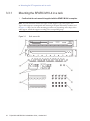
3.3 Mounting the Chassis in a Rack 37
3.3.1 Mounting the SPARC M10-4 in a rack 38
3.3.2 Mounting the PCI expansion unit in a rack 53
3.4 Mounting Optional Components 73
3.4.1 Mounting optional components in the SPARC M10-4 73
3.4.2 Mounting optional components in the PCI expansion unit 74
Chapter 4 Connecting Cables to the Chassis 75
4.1 Connecting Cables to the SPARC M10-4 75
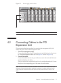
4.2 Connecting Cables to the PCI Expansion Unit 77
Chapter 5 Performing an Initial System Diagnosis 81
5.1 Connecting the System Management Terminal to the Chassis 81
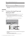
5.2 Turning on the Input Power and Starting the XSCF 82
5.3 Logging In to the XSCF 83
5.4 Checking the XCP Version 84
iv
Fujitsu M10-4/SPARC M10-4 Installation Guide ・ October 2015
5.5 Checking the Altitude Setting 84
5.6 Checking the Time Setting 85
5.7 Performing a Diagnosis Test 87
5.8 Checking the Component Status 89
Chapter 6 Making the Initial System Settings 93
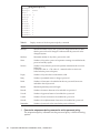
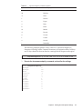
6.1 Setting the Password Policy 93
6.2 Setting a User Account and Password 96
6.3 Configuring the Telnet/SSH Service 98
6.3.1 Configuring the Telnet service 98
6.3.2 Configuring the SSH service 98
6.4 Configuring the HTTPS Service 99
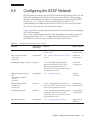
6.5 Configuring the XSCF Network 101
6.5.1 Setting an XSCF host name and domain name 102
6.5.2 Setting an Ethernet (XSCF-LAN) IP address 102
6.5.3 Setting the routing 103
6.5.4 Applying network settings 103
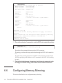
6.6 Configuring Memory Mirroring 104
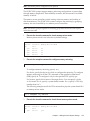
6.7 Creating a Physical Partition Configuration List (PCL) 106
6.8 Confirming that a System Board (PSB) is Assigned to a Physical
Partition (PPAR) 107
6.9 Setting a CPU Operational Mode for the Physical Partition 108
6.10 Synchronizing the Physical Partition (PPAR) Time and XSCF Time 110
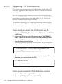
6.11 Registering a CPU Activation Key 111
6.11.1 CPU Activation key application conditions 111
6.11.2 Checking a CPU Activation key 111
6.11.3 Registering a CPU Activation key 112
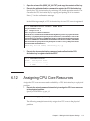
6.12 Assigning CPU Core Resources 113
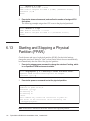
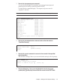
6.13 Starting and Stopping a Physical Partition (PPAR) 114
Appendix A Troubleshooting 117
A.1 Understanding the Usual Problems and Their Corrective Actions 117
Contents
v
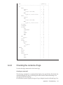
A.2 Understanding Commands for Troubleshooting 118
A.2.1 Checking the component status 118
A.2.2 Checking the contents of logs 121
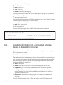
A.2.3 Checking information on a component where a failure or
degradation occurred 122
A.2.4 Checking diagnosis results 123
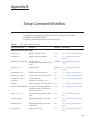
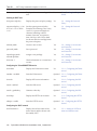
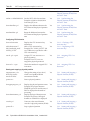
Appendix B Setup Command Workflow 125
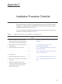
Appendix C Installation Procedure Checklist 131
vi
Fujitsu M10-4/SPARC M10-4 Installation Guide ・ October 2015
Preface
This document describes methods of installing and setting up the SPARC M10-4 from
Oracle or Fujitsu. The document assumes that the system has already been unpacked.
Fujitsu M10 is sold as SPARC M10 Systems by Fujitsu in Japan.
Fujitsu M10 and SPARC M10 Systems are identical products.
This preface includes the following sections:
Audience
■
■
Related Documentation
■
Text Conventions
■
Safety Precautions
■
Syntax of the Command-Line Interface (CLI)
■
Document Feedback
Audience
This document is designed for system administrators with advanced knowledge of
computer networks and Oracle Solaris, the service engineers who are in charge of
system maintenance, and field engineers.
Related Documentation
All documents for your server are available online at the following sites:
vii
■
■
Documents related to Oracle software (Oracle Solaris, etc.)
http://www.oracle.com/documentation/
Fujitsu documents
Japanese site
http://jp.fujitsu.com/platform/server/sparc/manual/
Global site
http://www.fujitsu.com/global/services/computing/server/sparc/downloads/manual/
The following table lists documents related to the SPARC M10 systems.
SPARC M10 systems-related documentation (*1)
Fujitsu M10/SPARC M10 Systems Getting Started Guide (*2)
Fujitsu M10/SPARC M10 Systems Quick Guide
Fujitsu M10/SPARC M10 Systems Important Legal and Safety Information (*2)
Software License Conditions for Fujitsu M10/SPARC M10 Systems
Fujitsu M10/SPARC M10 Systems Safety and Compliance Guide
Fujitsu M10/SPARC M10 Systems Security Guide
Fujitsu M10/SPARC M10 Systems/SPARC Enterprise/PRIMEQUEST Common Installation Planning Manual
Fujitsu M10-1/SPARC M10-1 Installation Guide
Fujitsu M10-4/SPARC M10-4 Installation Guide
Fujitsu M10-4S/SPARC M10-4S Installation Guide
Fujitsu M10-1/SPARC M10-1 Service Manual
Fujitsu M10-4/Fujitsu M10-4S/SPARC M10-4/SPARC M10-4S Service Manual
Crossbar Box for Fujitsu M10/SPARC M10 Systems Service Manual
PCI Expansion Unit for Fujitsu M10/SPARC M10 Systems Service Manual
Fujitsu M10/SPARC M10 Systems PCI Card Installation Guide
Fujitsu M10/SPARC M10 Systems System Operation and Administration Guide
Fujitsu M10/SPARC M10 Systems Domain Configuration Guide
Fujitsu M10/SPARC M10 Systems XSCF Reference Manual
Fujitsu M10/SPARC M10 Systems RCIL User Guide (*3)
Fujitsu M10/SPARC M10 Systems XSCF MIB and Trap Lists
Fujitsu M10/SPARC M10 Systems Product Notes
Fujitsu M10/SPARC M10 Systems Glossary
*1 The listed manuals are subject to change without notice.
*2 The printed manual comes with the product.
*3 This document applies specifically to the FUJITSU M10 and FUJITSU ETERNUS storage system.
viii Fujitsu M10-4/SPARC M10-4 Installation Guide ・ October 2015
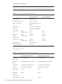
Text Conventions
This document uses the following fonts and symbols to express specific types of
information.
Font/Symbol
Meaning
Example
AaBbCc123
Indicates what you enter, in contrast to what is
displayed on the screen.
This font is used to indicate an example of
command input.
XSCF> adduser jsmith
AaBbCc123
Indicates the names of commands, files, and
directories displayed in computer output and on
the screen.
This font is used to indicate an example of
command input within the relevant framework.
XSCF> showuser -P
User Name: jsmith
Privileges: useradm
auditadm
Italic
Indicates the names of reference manuals.
See the Fujitsu M10-1/SPARC M10-1
Installation Guide.
""
Indicates the names of chapters, sections, items,
buttons, and menus.
See "Chapter 2 Network Connection."
Command syntax in the text
Though the XSCF commands have a section number of (8) or (1), it is omitted in the
text.
The Oracle Solaris commands have a section number such as (1M) in the text.
Each command has a section number in the command name when prompting users
to refer to it.
Safety Precautions
Read the following documents thoroughly before using or handling any SPARC M10
system:
■
Fujitsu M10/SPARC M10 Systems Important Legal and Safety Information
■
Fujitsu M10/SPARC M10 Systems Safety and Compliance Guide
Preface
ix
Syntax of the Command-Line Interface
(CLI)
The command syntax is as follows.
A variable that requires input of a value is in italics.
■
■
An optional element is enclosed in [ ].
■
A group of options for an optional keyword is enclosed in [ ] and delimited by |.
Document Feedback
If you have any comments or requests regarding this document, please contact us
from the following URL with the relevant manual number, manual title, and pages
along with specific details:
■
Japanese site
http://jp.fujitsu.com/platform/server/sparc/manual/
■
x
Global site
http://www.fujitsu.com/global/services/computing/server/sparc/downloads/manual/
Fujitsu M10-4/SPARC M10-4 Installation Guide ・ October 2015
Chapter 1
Understanding the Installation Flow
This chapter describes the required workflows for installation of the SPARC M10-4
and PCI expansion unit, broken up into the following sections.
For the overview, configuration, and specifications of the SPARC M10-4 and PCI
expansion unit, see the Fujitsu M10/SPARC M10 Systems Quick Guide.
■
Workflow for the SPARC M10-4
■
1.1
Workflow When Installing the PCI Expansion Unit
Workflow for the SPARC M10-4
The SPARC M10-4 is a 4U-size chassis that can be configured with up to 4 CPUs (32
or 64 cores). The building block cannot be configured. The SPARC M10-4 is used
alone.
This section describes the flow from SPARC M10-4 installation and installation of the
PCI expansion unit, which is an option mounted in the SPARC M10-4, to the initial
system settings.
The initial system settings are the settings implemented before system startup, and
they include the XSCF setup and CPU Activation setting. Skip the steps for the PCI
expansion unit if it is not to be installed.
By clicking a reference enclosed in " " to display a section, you can see the details of
the respective step. Italic font is used to indicate the name of a reference manual other
than this manual.
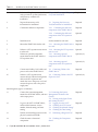
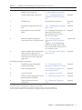
Table 1-1 Workflow for the SPARC M10-4
Step (work time (*1))
Work description
Reference
Installation work (approx. 38 minutes (*2))
1
Check the latest information available
in the Fujitsu M10/SPARC M10 Systems
Product Notes.
Fujitsu M10/SPARC M10 Systems
Product Notes
Required
1
Table 1-1 Workflow for the SPARC M10-4 (continued)
Step (work time (*1))
Work description
Reference
2
Before installing the system, check the
safety precautions, system specifications,
and necessary conditions for
installation.
"Chapter 2 Planning and Preparing
for System Installation"
Required
3
Prepare the necessary tools/
information for installation.
"3.1 Preparing the Necessary
Tools/Information for Installation"
Required
4
Confirm the delivered components.
"3.2.1 Confirming the delivered
components of the SPARC M10-4"
Required
"3.2.2 Confirming the delivered
components of the PCI expansion
unit"
Optional
5
Install the rack.
See the manual for each rack.
Required
6
Mount the SPARC M10-4 in the rack.
"3.3.1 Mounting the SPARC M10-4
in a rack"
Required
7
If there is a PCI expansion unit, mount
it in the rack.
"3.3.2 Mounting the PCI expansion
unit in a rack"
Optional
8
If there are optional components,
mount them on the SPARC M10-4 or
PCI expansion unit.
"3.4.1 Mounting optional
components in the SPARC M10-4"
Optional (*3)
"3.4.2 Mounting optional
components in the PCI expansion
unit"
Optional (*3)
9
Connect serial cables, LAN cables, and
power cords to the SPARC M10-4.
"4.1 Connecting Cables to the
SPARC M10-4"
Required
10
If there is a PCI expansion unit,
connect the link cable and management
cable to the PCI expansion unit.
Attach the core to the power cord, and
connect the power cord to the power
supply unit.
"4.2 Connecting Cables to the PCI
Expansion Unit"
Optional (*4)
Initial diagnosis (approx. 45 minutes)
11
Connect the system management
terminal to the SPARC M10-4, and turn
on the input power.
"5.1 Connecting the System
Management Terminal to the
Chassis"
"5.2 Turning on the Input Power
and Starting the XSCF"
Required
12
Log in to the XSCF of SPARC M10-4,
and check the firmware version
number, altitude setting, and time
setting.
"5.3
"5.4
"5.5
"5.6
Logging In to the XSCF"
Checking the XCP Version"
Checking the Altitude Setting"
Checking the Time Setting"
Required
13
Perform an initial diagnosis test on the
physical system board (PSB).
"5.7
Performing a Diagnosis Test"
Required
14
Check the status of mounted
components.
"5.8 Checking the Component
Status"
2
Fujitsu M10-4/SPARC M10-4 Installation Guide ・ October 2015
Required
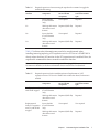
Table 1-1 Workflow for the SPARC M10-4 (continued)
Step (work time (*1))
Work description
Reference
Initial system settings (approx. 60 minutes)
15
Set the password policy.
"6.1
Setting the Password Policy"
16
Set a user account and password.
"6.2 Setting a User Account and
Password"
Required
17
Configure the telnet or SSH service.
"6.3 Configuring the Telnet/SSH
Service"
Required
18
Configure the HTTPS service.
"6.4 Configuring the HTTPS
Service"
Required
19
Configure the XSCF network.
"6.5 Configuring the XSCF
Network"
Required
20
When duplicating memory, configure
memory mirroring.
"6.6 Configuring Memory
Mirroring"
Optional
21
Set the configuration policy for a
physical partition.
"6.7 Creating a Physical Partition
Configuration List (PCL)"
Optional (*5)
22
Confirm that the system board (PSB) is
assigned to a physical partition (PPAR).
"6.8 Confirming that a System
Board (PSB) is Assigned to a
Physical Partition (PPAR)"
Required
23
Set a CPU operational mode for the
physical partition.
"6.9 Setting a CPU Operational
Mode for the Physical Partition"
Optional
24
Clear the difference between the
system time and physical partition
(PPAR) time.
"6.10 Synchronizing the Physical
Partition (PPAR) Time and XSCF
Time"
Required
25
Add a CPU Activation key to the
system.
"6.11
Key"
Required
(*6)
26
Assign CPU resources to the physical
partition.
"6.12 Assigning CPU Core
Resources"
Required
27
Confirm the start/stop of the physical
partition and the connection of the
console.
"6.13 Starting and Stopping a
Physical Partition (PPAR)"
Required
Registering a CPU Activation
Required
*1 Average work time
*2 Time required for mounting optional components and installing the PCI expansion unit is not included.
*3 If the optional components are ordered together with the SPARC M10-4, they are shipped mounted to the SPARC M10-4. If the PCI
expansion unit is also ordered, the optional components are shipped mounted to the PCI expansion unit.
*4 The link card is shipped mounted to the SPARC M10-4.
*5 The physical partition configuration information is already set.
*6 One CD-ROM disk containing a CPU Activation certificate is provided with the system. The CPU Activation key may be registered
with the system.
Note - The SPARC M10 systems have Oracle Solaris preinstalled. According to the purpose,
either use the preinstalled Oracle Solaris as is or reinstall it.
To reinstall Oracle Solaris, install the latest Oracle VM Server for SPARC. For the latest
information on the supported Oracle Solaris versions and SRU, see the Fujitsu M10/SPARC
M10 Systems Product Notes.
Chapter 1 Understanding the Installation Flow
3
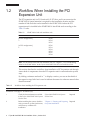
1.2
Workflow When Installing the PCI
Expansion Unit
The PCI expansion unit is a 2U chassis with 11 PCI slots, and it can connect to the
SPARC M10-4. Special attention is required for the installation location and the
number of link cards that can be installed in the SPARC M10-4 when the PCI
expansion unit is installed in the SPARC M10-4. Install link cards according to the
Table 1-2 rules.
Table 1-2 SPARC M10-4 link card installation rule
Maximum installable number
Link card installation location
[2-CPU configuration]
3
PCI#0
PCI#3
PCI#7
[4-CPU configuration]
6
PCI#0
PCI#1
PCI#3
PCI#5
PCI#7
PCI#9
Note - For the details on the link card installation rule, see "Chapter 2 PCI Card Mounting
Rules for the SPARC M10-4" in the Fujitsu M10/SPARC M10 PCI Card Installation Guide.
This section describes the workflows from installation of PCI expansion unit through
status check of components when the PCI expansion unit is connected under system
stop.
By clicking a reference enclosed in " " to display a section, you can see the details of
the respective step. Italic font is used to indicate the name of a reference manual other
than this manual.
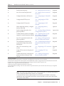
Table 1-3 Workflow when installing the PCI expansion unit
Step (work time (*1))
Work description
Reference
Installation work (approx. 38 minutes (*2))
1
Check the latest information available
in the Fujitsu M10/SPARC M10 Systems
Product Notes.
Fujitsu M10/SPARC M10 Systems
Product Notes
Required
2
Before installing the system, check the
safety precautions, system specifications,
and necessary conditions for
installation.
"Chapter 2 Planning and Preparing
for System Installation"
Required
4
Fujitsu M10-4/SPARC M10-4 Installation Guide ・ October 2015
Table 1-3 Workflow when installing the PCI expansion unit (continue d)
Step (work time (*1))
Work description
Reference
3
Prepare the necessary tools/
information for installation.
"3.1 Preparing the Necessary
Tools/Information for Installation"
Required
4
Confirm the delivered components.
"3.2.2 Confirming the delivered
components of the PCI expansion
unit"
Required
5
Install the rack.
See the manual for each rack.
Required
(*3)
6
Mount the PCI expansion unit in the
rack.
"3.3.2 Mounting the PCI expansion
unit in a rack"
Required
7
Install the link card on the SPARC
M10-4.
"8.5 Installing a PCI Express Card"
in the Fujitsu M10-4/Fujitsu
M10-4S/SPARC M10-4/SPARC
M10-4S Service Manual
Required
8
If there are optional components,
mount them on the PCI expansion unit.
"3.4.2 Mounting optional
components in the PCI expansion
unit"
"Chapter 2 PCI Card Mounting
Rules for the SPARC M10-4" in the
Fujitsu M10/SPARC M10 Systems PCI
Card Installation Guide
Optional (*4)
9
Connect the link cable and management
cable to the PCI expansion unit.
Attach the core to the power cord, and
connect the power cord to the power
supply unit.
"4.2 Connecting Cables to the PCI
Expansion Unit"
Required
Initial diagnosis (approx. 45 minutes)
10
Connect the system management
terminal to the M10-4.
"5.1 Connecting the System
Management Terminal to the Chassis"
Required
11
Turn on the input power.
"5.2 Turning on the Input Power
and Starting the XSCF"
Required
12
Log in to the XSCF.
"5.3
Logging In to the XSCF"
Required
13
Perform an initial diagnosis test on the
physical system board (PSB).
"5.7
Performing a Diagnosis Test"
Required
14
Check the status of mounted
components.
"5.8 Checking the Component
Status"
Required
*1 Average work time
*2 Time required for mounting optional components is not included.
*3 This is not necessary if the PCI expansion unit is installed in an empty space in the installed rack.
*4 If the optional components are also ordered, they are shipped mounted to the PCI expansion unit.
Chapter 1 Understanding the Installation Flow
5
1.2.1
Points to note on configurations with the PCI
expansion unit connected
If you install a PCI expansion unit, keep the following points in mind.
■
If the PCI expansion unit to be installed has PCIe cassettes, remove the PCIe
cassettes with mounted PCIe cards from the PCI expansion unit. Then, connect the
PCI expansion unit to the SPARC M10-4 so that Oracle Solaris in a logical domain
(control domain or root domain) can recognize the PCI expansion unit.
Install the PCIe cassettes with mounted PCIe cards in the PCI expansion unit
where Oracle Solaris in the logical domain (control domain or root domain)
recognizes the PCI expansion unit. Incorporate the PCIe cards of the PCI
expansion unit in Oracle Solaris in the logical domain (control domain or root
domain).
■
■
■
Before installing the PCI expansion unit, execute the ldm list-constraints -x
command of the Oracle Solaris in the control domain to save the configuration
information of the logical domains to an XML file.
If the logical domain configuration resets to the factory-default state as a result of
restarting the physical partition, execute the ldm init-system -i command on
Oracle Solaris in the control domain to restore the configuration information of the
logical domains from the XML file.
If you execute the setpciboxdio command of the XSCF firmware to set the
enabling/disabling setting of the direct I/O function of the PCI expansion unit,
perform it before you execute the addboard command to install the system board
with the PCI expansion unit connected on the physical partition.
When you have changed the setting of the direct I/O function with the setpciboxdio
command of the XSCF firmware, do not restart the logical domains until you
execute the ldm add-spconfig command of the Oracle Solaris in the control
domain to save the logical domain configuration in XSCF.
Suppose that one of the following operations is performed with the setpciboxdio
command using the XCP 2044 or later on the SPARC M10-4. Then, the logical domain
configuration of the physical partition will return to the factory-default state at the
next control domain start time. Also, the OpenBoot PROM environment variables
of the control domain will be initialized.
■
Changing the enable/disable setting of the direct I/O function for the PCI
expansion unit
■
Installing/removing/replacing a PCI expansion unit in a PCI slot of a SPARC
M10-4 chassis where the direct I/O function for the PCI expansion unit is enabled
You can execute the setpciboxdio command regardless of whether there is a PCI
expansion unit. Before doing so, save the logical domain configuration information
from Oracle Solaris to an XML file. Also, write down the setting information for the
OpenBoot PROM environment variables of the control domain to set it again.
Table 1-4 indicates what information may need to be saved/restored when changing
the enable/disable setting of the direct I/O function for the PCI expansion unit by
executing the setpciboxdio command.
6
Fujitsu M10-4/SPARC M10-4 Installation Guide ・ October 2015
Table 1-4 Required operations when executing the setpciboxdio command to toggle the
enable/disable setting
PCI expansion unit
connected
Current domain
configuration
Rebuilding Oracle VM
Server for SPARC
configuration
Setting OpenBoot PROM
environment variables
again
No
factory-default
(Control domain
only)
Not required
Required
No
With logical domains
other than control
domain
Required (XML file)
Required
Yes
factory-default
(Control domain
only)
Not required
Required
Yes
With logical domains
other than control
domain
Required (XML file)
Required
Table 1-5 indicates what information may need to be saved/restored when
installing/removing/replacing a PCI expansion unit in a PCI slot of a SPARC M10-4
chassis where the direct I/O function for the PCI expansion unit is enabled. Here, the
setpciboxdio command has been executed to enable the function.
Note - In PCI expansion unit maintenance using the PCI hot plug (PHP) function, the direct
I/O function is disabled, so the above information does not need to be saved/restored.
Table 1-5 Required operations for the installation/removal/replacement of a PCI
expansion unit in a PCI slot of a SPARC M10-4 where the direct I/O function is
enabled
Maintenance environment
Current domain
configuration
Rebuilding Oracle VM
Server for SPARC
configuration
Setting OpenBoot PROM
environment variables
again
Installation/removal
with PPAR stopped
factory-default
(Control domain
only)
Not required
Not required
With logical domains
other than control
domain
Required (XML file)
Required
factory-default
(Control domain
only)
Not required
Not required
With logical domains
other than control
domain
Required (XML file)
Required
Replacement of
faulty PCI expansion
unit (*1) with PPAR
stopped
Chapter 1 Understanding the Installation Flow
7
Table 1-5 Required operations for the installation/removal/replacement of a PCI
expansion unit in a PCI slot of a SPARC M10-4 where the direct I/O function is
enabled (continue d)
Maintenance environment
Current domain
configuration
Rebuilding Oracle VM
Server for SPARC
configuration
Setting OpenBoot PROM
environment variables
again
Replacement of
normal PCI
expansion unit (*1)
with PPAR stopped
factory-default
(Control domain
only)
Not required
Not required
With logical domains
other than control
domain
Not required
Not required
*1 This includes even the replacement of a link card, link cable, management cable, and link board.
Note - Execute the ldm list-constraints -x command to save it to an XML file, and execute the
ldm init-system -i command to restore it from an XML file. To display the information of
OpenBoot PROM environment, execute the printenv command at the ok prompt. For details
on these steps, see "1.7.3 How to save/restore the logical domain configuration information
and the OpenBoot PROM environment variable" in the PCI Expansion Unit for Fujitsu
M10/SPARC M10 Systems Service Manual.
8
Fujitsu M10-4/SPARC M10-4 Installation Guide ・ October 2015
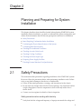
Chapter 2
Planning and Preparing for System
Installation
This chapter describes what should be checked when planning SPARC M10 system
installation. Before installation, you need to understand the system configuration and
obtain all the information that will become prerequisite conditions for installation.
■
Safety Precautions
2.1
■
Items Requiring Confirmation before Installation
■
Confirming the Physical Specifications of the System
■
Confirming Rack Specifications
■
Checking Environmental Conditions
■
Checking Acoustic Noise Levels
■
Checking Cooling Conditions
■
Checking the Power Input Type
■
Preparing Power Supply Facilities
■
Checking External Interface Port Specifications
Safety Precautions
This section describes precautions regarding installation of the SPARC M10 systems.
Be sure to follow the precautions below when performing installation work. Failure
to do so may lead to damage to the device or a malfunction.
■
Follow all the stated precautions, warnings, and instructions for the chassis.
■
■
Do not insert any foreign object into the chassis openings. Any object that touches
a high-voltage part or causes a component to short circuit may lead to fire or
electric shock.
Contact a service engineer for details of chassis inspection.
Safety precautions when working with electricity
■
Verify that both the voltage and frequency of input power match the voltage and
9
frequency indicated on the electrical rating label affixed to the chassis.
■
■
■
■
Make sure to wear a wrist strap when handling the internal disk (HDD/SSD),
memory, CPU memory unit (upper/lower unit), or other printed circuit boards.
Make sure to use grounded power outlets.
Do not make mechanical or electrical modifications to the chassis. We do not take
responsibility for regulatory compliance of a modified chassis.
Do not disconnect a power cord from the chassis while the power is on.
Safety precautions regarding racks
■
■
■
Racks must be fixed to the floor, ceiling, or nearest frame.
The quakeresistant options kit may be supplied with the racks. The use of the
quakeresistant options kit prevents the rack from toppling over when the chassis
is pulled out from the slide rails for installation or maintenance.
In the following cases, a safety evaluation must be performed by a service
engineer before installation or maintenance.
- If the quakeresistant options kit is not supplied and the rack is not fixed with
bolts to the floor, a service engineer confirms the safety of the rack, such as by
verifying that it does not topple over when the chassis is pulled out from the
slide rails.
- If the rack is mounted on a raised floor, a service engineer confirms that the floor
can withstand the load when the chassis is pulled out from the slide rails. Fix the
rack to the concrete floor beneath the raised floor by using the original mounting
kit that serves this purpose.
■
If multiple chassis are mounted in the rack, perform maintenance on one chassis at
a time.
Safety precautions regarding installation work
■
With this chassis installed in a closed or multi-unit rack assembly, the ambient
temperature inside the rack operating environment may be greater than the
ambient room temperature. Therefore, consideration must be given to installing
the chassis in an environment compatible with the manufacturer's maximum rated
ambient temperature.
- Consideration of air-conditioning adjustments, such as with air circulation, is
needed to prevent the ambient temperature inside the rack from exceeding the
maximum ambient operating temperature of this chassis.
- Maximum ambient operating temperature of this chassis: 35°C
■
The installation of the chassis in a rack should allow for sufficient air flow for the
chassis to operate safely.
- This chassis has ventilation slits at the front and rear of the chassis.
- To prevent overheating, do not cover or close these ventilation slits.
■
10
The mounting of the chassis in the rack should not create any hazardous condition
due to uneven mechanical loading. To keep the entire rack stable, fix the rack to
the wall or floor by suitable means.
- Be careful not to injure yourself or others when installing the chassis in the rack.
Fujitsu M10-4/SPARC M10-4 Installation Guide ・ October 2015
- Do not install this chassis in the rack if the chassis may make the entire rack
unstable.
- Weight of this chassis in the maximum configuration:
Model SP-4SNB (SPARC M10-4): 58 kg
Model SP-PCI-BOX (SPARC PCI-BOX): 22 kg
■
■
If the chassis is supplied power from a power strip or the service outlet of another
chassis, it may overload the power strip or the power cord of the other chassis.
- Confirm that the power strip or the power cord of the service outlet exceeds the
combined ratings of all the equipment to which it supplies power.
Electrical ratings of this chassis:
Model SP-4SNB: 200-240 VAC, 15.0-12.5 A, 50/60 Hz, single phase (maximum 2
inputs)
Model SP-PCI-BOX: 100-120/200-240 VAC, 5.0-4.2/2.5-2.1 A, 50/60 Hz, Single
phase (Maximum 2 inputs)
Be sure to securely ground the rack-mounted equipment. Pay particular attention
to power supply connections other than the direct connections to branch circuits
(e.g., use of power strips).
Caution - If all the power cords of this chassis are connected to one power strip, a
high leakage current may flow through the grounding wire of the power strip. Be
sure to connect the wire to ground before connecting the power supply. If the power
strip is not directly connected to a branch circuit, a power strip that has an
industrial-type attachment plug must be used.
■
Install this equipment such that it is near a wall and a power outlet is easily
accessible.
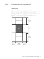
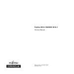
- Rack configuration
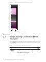
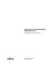
Note - Products must be mounted from the lower rack when they are mounted in a rack.
Chapter 2 Planning and Preparing for System Installation
11
Figure 2-1 Rack configuration (for the PCI expansion unit)
PCI-BOX (2U)
PCI-BOX (2U)
PCI-BOX (2U)
PCI-BOX (2U)
PCI-BOX (2U)
PCI-BOX (2U)
PCI-BOX (2U)
PCI-BOX (2U)
PCI-BOX (2U)
PCI-BOX (2U)
PCI-BOX (2U)
PCI-BOX (2U)
PCI-BOX (2U)
PCI-BOX (2U)
PCI-BOX (2U)
PCI-BOX (2U)
PCI-BOX (2U)
PCI-BOX (2U)
PCI-BOX (2U)
PCI-BOX (2U)
PCI-BOX (2U)
PCI-BOX: PCI expansion unit
2.2
Items Requiring Confirmation before
Installation
This section describes the items that you need to confirm before installing the SPARC
M10 system. Before starting installation work, confirm that the requirements in Table
2-1 have been met.
Table 2-1 List of items requiring confirmation before installation
Check item
System
configuration
Check
column
- Has the system configuration been determined?
- Has the required rack space been confirmed?
- Has the number of racks been decided?
Training
12
- Have the system administrator and operators attended the
required training courses?
Fujitsu M10-4/SPARC M10-4 Installation Guide ・ October 2015
Table 2-1 List of items requiring confirmation before installation (continued)
Check item
Installation
location
Check
column
- Has the system installation location been determined?
- Does the placement of each chassis meet the service area
requirements?
- Have the chassis been placed so that their air intakes do not
take in exhaust from other equipment?
- Have the rack installation requirements been met?
Access route
- Has the access route for the rack been secured?
Environmental
conditions
- Does the installation location meet the temperature and
humidity conditions?
- Can the environmental conditions at the installation location
be thoroughly maintained and controlled?
- Have security measures been established for the installation
location?
- Does the installation location have sufficient fire extinguishing
equipment?
Power supply
facilities
- Do you know the voltage available for the racks where each
chassis and peripheral will be mounted?
- Are the power supply facilities sufficient for the individual
chassis, monitors, and peripherals?
- Are the power supply facilities within an appropriate
distance from the racks?
Network
specifications
- Do you have the necessary information for network
connections?
CPU Activation
- Has the volume of resources to be used during initial
installation been determined?
- Have the required CPU Activations been ordered?
2.3
Confirming the Physical Specifications
of the System
This section describes the physical specifications of the system that require
confirmation before installation. Confirm that the installation location meets these
requirements.
Chapter 2 Planning and Preparing for System Installation
13
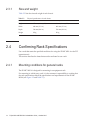
2.3.1
Size and weight
Table 2-2 lists the size and weight of each chassis.
Table 2-2 Physical specifications of each chassis
2.4
Item
SPARC M10-4
PCI expansion unit
Height
175 mm (6.9 in.) (4U)
86 mm (3.4 in.) (2U)
Width
440 mm (17.3 in.)
440 mm (17.3 in.)
Depth
746 mm (29.4 in.)
750 mm (29.5 in.)
Weight
58 kg
22 kg
Confirming Rack Specifications
Use a rack that meets the specified conditions for using the SPARC M10-4 or the PCI
expansion unit.
This section describes the items that must be confirmed to use a rack
2.4.1
Mounting conditions for general racks
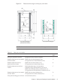
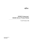
The SPARC M10-4 is designed for mounting in an equipment rack.
For mounting in a third-party rack, it is the customer's responsibility to confirm that
the rack specifications match the specifications and requirements for the SPARC
M10-4 (see Figure 2-2 and Table 2-3).
14
Fujitsu M10-4/SPARC M10-4 Installation Guide ・ October 2015
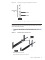
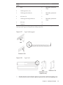
Figure 2-2 Dimensional drawings for third-party rack checks
FRONT
Rack column hole diagram
Rack horizontal diagram
(horizontal cross section)
Note - The dimensions shown in the conditions do not include any protrusions.
Table 2-3 Third-party rack checklist
Description
Condition
Letter in
figure
Rack type/Compliance standards
Equipment rack/EIA standard-compliant
--
Dimension between rear door (inside)
and front column
SPARC M10-4: At least 844 mm (33.2 in.)
PCI expansion unit: At least 848 mm (33.4 in.)
A
Dimension between front door
(inside) and front column
SPARC M10-4: At least 32 mm (1.3 in.)
PCI expansion unit: At least 24 mm (0.9 in.)
B
Dimension between front and rear
columns
Within adjustment range of rack mount kit
Adjustment range of the mount kit for each server
SPARC M10-4: 630 mm (24.8 in.) to 840 mm (33.1 in.)
PCI expansion unit: 630 mm (24.8 in.) to 840 mm (33.1 in.)
C
Dimension between rear door (inside)
and rear column
SPARC M10-4: At least 158 mm (6.2 in.)
PCI expansion unit: At least 158 mm (6.2 in.)
D
Front panel mounting space of chassis
At least 483 mm (19.0 in.)
E
Chapter 2 Planning and Preparing for System Installation
15
Table 2-3 Third-party rack checklist (continued)
Description
Condition
Letter in
figure
Distance between left and right
chassis attachment holes (common to
front and rear columns)
465 mm (18.3 in.)
F
Distance between left and right
columns (common to front and rear
columns)
At least 450 mm (17.7 in.)
G
Column thickness
2 mm (0.08 in.) to 2.5 mm (0.1 in.)
H
Structures other than columns
Rack has no structures between front and rear columns
I
Cable hatch
Rack has hatch on bottom surface, rear door, or elsewhere
J
Area of door vent openings
Front door: At least 73 % of door area
Rear door: At least 73 % of door area
K
Size of chassis attachment holes
(common to front and rear columns)
Square hole with sides longer than 9.2 mm (0.36 in.) and not
longer than 9.8 mm (0.38 in.) (*1) or M6 screw hole
L
Vertical pitch of chassis attachment
holes
(common to front and rear columns)
EIA standards, universal pitch
M
Door opening angle
Door opens to 130°
--
Strength
Rack has necessary strength/load capacity for mounting
chassis
--
Grounding
Rack and units can be grounded
--
Toppling prevention measures
Rack can be prevented from toppling over
--
Earthquake resistance measures
Earthquake resistance measures can be implemented for rack
--
*1 If the SPARC M10-4 and the PCI expansion unit have square holes with sides of 9.0 mm (0.35 in.) to 9.2 mm (0.36 in.), a separate rack
mount kit must be ordered.
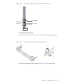
■
Mounting on the lowest shelf of the rack
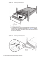
For the SPARC M10-4, the cable support at the chassis rear moves underneath the
chassis during maintenance, so do not mount the chassis on the lowest shelf (1U)
of the rack.
■
Other conditions
In addition to structural conditions, the following condition must be taken into
consideration.
- Install the rack such that the temperature inside the rack meets the temperature
conditions for cooling the chassis when mounted in the rack. For details, see "2.5
Checking Environmental Conditions." Particularly, make sure that exhaust
from the chassis does not re-enter the chassis through the air intakes. This
requires measures such as covering the front and rear of empty spaces inside the
rack.
16
Fujitsu M10-4/SPARC M10-4 Installation Guide ・ October 2015
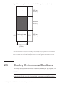
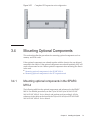
2.4.2
Installation area for a general rack
Service areas
Service area requirements vary depending on the rack used.
When mounting each chassis in the designated rack, see the examples of service areas
in Figure 2-3 and Figure 2-4. The rack width depends on the rack used.
When using a rack other than the designated rack, see the manual for the rack used.
Figure 2-3 Example of service areas for the SPARC M10-4 (top view)
600 mm
(23.6 in.)
Rear service area
900 mm
(35.4 in.)
Rack
1050 mm
(41.3 in.)
Front service area
1200 mm
(47.2 in.)
700 mm
(27.6 in.)
600 mm
(23.6 in.)
Chapter 2 Planning and Preparing for System Installation
17
Figure 2-4 Example of service areas for the PCI expansion unit (top view)
(*1)
Rear service area
800 mm
(31.5 in.)
Rack
105 0 mm
(41.3 in.)
Front service area
(*1)
(*1)
900 mm
(35.4 in.)
700 mm
(27.6 in.)
*1 To mount a chassis on the rack, an area with a depth of 1,200 mm (47.2 in.) is required in front of the rack, and
areas with a width of 600 mm (23.6 in.) are required on both the left and right sides of the front service area. If
there is a possibility that a chassis will be added later, secure an area with a depth of 1,200 mm (47.2 in.) in front
of the rack and areas with a width of 600 mm (23.6 in.) on both the left and right sides of the front service area.
2.5
Checking Environmental Conditions
This section describes the environmental conditions for the SPARC M10 systems. The
server can be installed at locations that meet the environmental conditions listed in
Table 2-4.
Note - When designing environmental control systems such as air conditioning facilities,
confirm that the air taken in by each chassis meets the requirements specified in this section.
18
Fujitsu M10-4/SPARC M10-4 Installation Guide ・ October 2015
The environmental conditions described in Table 2-4 reflect test results from each
chassis. The optimal conditions represent the recommended environment in
operation. The component failure rate may increase substantially when the system
operates for prolonged periods in an environment that is at or close to the operationtime (in operation) limit values, or when the system is installed in an environment
that is at or close to the non-operation-time (not in operation) limit values. To
minimize the occurrence of system downtime due to a component failure, set the
temperature and humidity within the optimal condition range.
The following conditions must be met to prevent overheating:
■
Neither warm air nor hot air blows directly on the front of the rack
■
Neither warm air nor hot air blows directly on the front panel of any chassis
Table 2-4 Environmental conditions
Item
In operation
Not in operation
Optimal
condition
Ambient
temperature
5°C to 35°C
41°F to 95°F
- When unpacked
0°C to 50°C
(32°F to 122°F)
- When still packed
-25°C to 60°C
(-4°F to 140°F)
21°C to
23°C
70°F to
74°F
Relative
humidity
(*1)
- When installed in server room
20% RH to 80% RH
- When installed in office (*2)
20% RH to 80% RH
- When installed in
server room
8% RH to 80% RH
- When installed in
office (*2)
8% RH to 80% RH
45% RH or
higher but
less than
50% RH
Maximum
wet-bulb
temperature
- When installed in server room
26°C (78.8°F)
- When installed in office (*2)
29°C (84.2°F)
- When installed in
server room
27°C (80.6°F)
- When installed in
office (*2)
29°C (84.2°F)
Altitude limit
(*3)
0 m to 3,000 m
(0 ft. to 10,000 ft.)
0 m to 12,000 m
(0 ft. to 40,000 ft.)
Chapter 2 Planning and Preparing for System Installation
19
Table 2-4 Environmental conditions (continue d)
Item
In operation
Temperature
conditions
- When installed at 0 m to 500 m (0 ft.
to 1,640 ft.)
5°C to 35°C (41°F to 95°F)
- When installed at 500 m to 1,000 m
(1,644 ft. to 3,281 ft.)
5°C to 33°C (41°F to 91.4°F)
- When installed at 1,000 m to 1,500 m
(3,284 ft. to 4,921 ft.)
5°C to 31°C (41°F to 87.8°F)
- When installed at 1,500 m to 3,000 m
(4,925 ft. to 9,843 ft.)
5°C to 29°C (41°F to 84.2°F)
Not in operation
Optimal
condition
*1 No condensation is assumed regardless of temperature and humidity conditions.
*2 Only the PCI expansion unit can be installed in an office. Install the SPARC M10-4 in a dedicated room such as
a server room.
*3 All the altitudes indicate heights above sea level.
2.5.1
Ambient temperature
To maintain system reliability and operator comfort, the optimal ambient temperature
is 21°C to 23°C (70°F to 74°F). This temperature range makes it easy to maintain the
relative humidity. While the system is operating within this range, even a failure of
the air conditioning facilities does not cause it to suddenly stop.
2.5.2
Ambient relative humidity
To process data safely, the optimal ambient relative humidity is 45% or higher but
less than 50%. The reasons for this are as follows:
■
A humidity in the optimum range can protect the system from corrosion issues
caused by high humidity
■
■
A humidity in the optimum range means that even a failure of the air conditioning
facilities does not cause the system to suddenly stop
A humidity in the optimum range can prevent failures and malfunctions caused
by electrostatic discharge
A relative humidity that is too low is conducive to generating a static electricity
discharge. The resulting intermittent interference may cause a failure or temporary
malfunction.
Electrostatic discharge is more likely to occur and harder to eliminate at locations
with a relative humidity below 35%. Electrostatic discharge becomes a critical issue
when the relative humidity falls below 30%. The set optimal relative humidity range
20
Fujitsu M10-4/SPARC M10-4 Installation Guide ・ October 2015
is stricter than the guidelines applied to indoor locations with more relaxed
environmental conditions such as general office environments. However, if the server
is installed in a server room, this condition is not difficult to meet because server
rooms utilize highly efficient moisture-proof materials and have fewer ventilation
cycles.
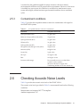
2.5.3
Contaminant conditions
Table 2-5 provides the acceptable reference values for contaminants with regard to
the SPARC M10 systems.
Table 2-5 Acceptable reference values for contaminants
2.6
Contaminant
Acceptable reference value
Hydrogen sulfide (H2S)
7.1 ppb or less
Sulfurous acid gas (sulfur oxide) (SO2)
37 ppb or less
Hydrogen chloride (HCI)
6.6 ppb or less
Chlorine (CI2)
3.4 ppb or less
Hydrogen fluoride (HF)
3.6 ppb or less
Nitrogen dioxide (nitrogen oxide) (NO2)
52 ppb or less
Ammonia (NH3)
420 ppb or less
Ozone (O3)
5 ppb or less
Oil vapor
0.2 mg/m3 or less
Dust
0.15 mg/m3 or less
Seawater (salt damage)
Do not install out at sea or within 500 m
(1,640.4 ft.) of the seashore.
(However, this does not apply if air
conditioning facilities do not use outside air.)
Checking Acoustic Noise Levels
Table 2-6 provides the acoustic noise levels of the SPARC M10-4.
The acoustic noise levels provided in Table 2-6 are measured based on the following
conditions.
Measurement environment: ISO 7779 compliant
Ambient temperature: 23°C
Chapter 2 Planning and Preparing for System Installation
21
Table 2-6 Acoustic noise levels of the SPARC M10-4
Acoustic noise level
CPU type
CPU configuration
In operation
When idle
Sound power level
SPARC64 X
2 CPUs
7.5 B
6.9 B
4 CPUs
8.2 B
6.9 B
2 CPUs
8.5 B
7.0 B
4 CPUs
9.0 B
7.0 B
2 CPUs
58 dB
56 dB
4 CPUs
64 dB
56 dB
2 CPUs
67 dB
57 dB
4 CPUs
74 dB
57 dB
SPARC64 X+
Sound pressure level
SPARC64 X
SPARC64 X+
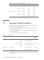
2.7
Checking Cooling Conditions
This section describes the cooling conditions for the SPARC M10 systems. Note the
following conditions when installing the system:
■
The air conditioning facilities for the room are sufficient to meet the cooling
conditions of the entire system
■
The air conditioning facilities have control functions for preventing excessive
temperature changes
Table 2-7 lists the cooling conditions for each chassis.
Table 2-7 Cooling conditions
Configuration
Input voltage
CPU type
Region
Maximum heat dissipation
Maximum
exhaust
airflow
SPARC M10-4
200 to 240 VAC
SPARC64 X
Japan
10,410 kJ/hr (9,864 BTU/hr)
17.1 m3/min
Outside
Japan
9,954 kJ/hr (9,434 BTU/hr)
Japan
11,550 kJ/hr (10,950 BTU/hr)
Outside
Japan
11,100 kJ/hr (10,520 BTU/hr)
SPARC64 X+
PCI expansion
unit
AC100 - 120 V
-
-
1,005 kJ/hr (953 BTU/hr)
200 to 240 VAC
-
-
972 kJ/hr (921 BTU/hr)
18.7 m3/min
4.5 m3/min
The SPARC M10 systems are designed to function in an environment with natural
convection airflow.
22
Fujitsu M10-4/SPARC M10-4 Installation Guide ・ October 2015
The following requirements must be followed to meet the environmental specifications.
■
Ensuring sufficient airflow for the entire system
Each chassis is equipped with a cooling function for front-to-rear cooling. Each
chassis has air vents on the front. Exhaust is expelled from the rear of each chassis.
The SPARC M10 systems use internal fans whose airflow reaches the maximum
exhaust airflow shown in Table 2-7 under normal operating conditions.
Example: 17.1 m3 (603.8 ft.3) per minute for each SPARC M10-4 unit
■
2.8
Ensuring that temperature at the intake part of each chassis does not exceed the
limit value
Other devices mounted in the rack must not cause the temperature at the intake
part of any chassis to exceed the limit value. This limit value in environmental
conditions assumes that each chassis operates with the rack door closed.
Checking the Power Input Type
This section describes the power input types that can be used with the SPARC M10
systems. To prevent serious accidents, confirm that the power supply facilities can
supply sufficient redundant power to the system.
The server can use the following power input types:
■
Redundant configuration of power supply units
2.8.1
■
Dual power feed
■
Three-phase power feed
■
Uninterruptible power supply (UPS) connection (optional)
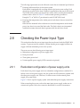
Redundant configuration of power supply units
Each chassis has power supply units in a redundant configuration as standard. If a
failure occurs in one power supply unit, the system can still continue to operate with
the other power supply unit. However, if a failure occurs in the external power
supply, the system stops.
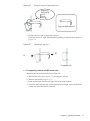
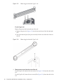
Figure 2-5 shows a power supply system with redundant power supply connections.
When connecting the power cords to the same input power supply, make sure to
connect each power cord to the connection destination in a one-to-one manner.
Chapter 2 Planning and Preparing for System Installation
23
Figure 2-5 Power supply system with redundant power supply connections
AC IN#1
AC IN#0
AC power
CB
CB
2.8.2
CB: Circuit breaker
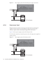
Dual power feed
Dual power feed is an option for receiving power feeds from two external power
supplies. If a failure occurs in one external power supply, the system can still
continue to operate with the external power supply on the other system.
Figure 2-6 shows a power supply system with dual power feed.
For dual system connections, connect the power cords to the input power supplies on
separate systems.
Figure 2-6 Power supply system with dual power feed
AC IN#1
AC IN#0
AC power
CB
CB
24
Fujitsu M10-4/SPARC M10-4 Installation Guide ・ October 2015
CB: Circuit breaker
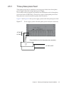
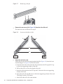
2.8.3
Three-phase power feed
Three-phase power feed is a method of receiving power feeds from a three-phase
power supply rather than a single-phase power supply.
The customer needs to prepare an external power distribution unit for three-phase
power feed for the SPARC M10-4. There are two types of three-phase power feed:
three-phase star connection and three-phase delta connection.
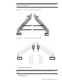
Figure 2-7 and Figure 2-8 show power supply systems with three-phase power feed.
Figure 2-7 Power supply system with three-phase power feed (star connection)
AC IN#1
AC IN#0
Power distribution box (for three phase star connection)
AC 380 to 415V
Chapter 2 Planning and Preparing for System Installation
25
Figure 2-8 Power supply system with three-phase power feed (delta connection)
AC IN#1
AC IN#0
Power distribution box (for three phase delta connection)
AC 200 to 240V
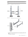
2.8.4
Uninterruptible power supply (UPS) connection
(optional)
Using an uninterruptible power supply (UPS) enables the stable supply of electrical
power to the system in case of power failure, widespread power outage, etc.
If the customer has ordered UPSs, use a separate UPS for each power supply system.
Connect PSU#0 and PSU#1 to the input power supplies of different systems.
Figure 2-9 shows a power supply system with three-phase power feed.
26
Fujitsu M10-4/SPARC M10-4 Installation Guide ・ October 2015
Figure 2-9 Power supply system with UPS connections
AC IN#1
AC IN#0
CB
UPS#0
AC#0
CB
UPS#1
AC#1
CB: Circuit breaker
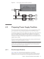
2.9
Preparing Power Supply Facilities
This section describes the electrical specifications, power cord specifications, facility
power requirements, and grounding requirements of the SPARC M10 systems.
To minimize component failure rates, stable power supply such as with a dual power
feed or uninterruptible power supply (UPS) must be prepared. The component
failure rate is likely to be higher when the system operates in an environment with
frequent power outages or unstable power supply than in an environment where the
supply of power is stable.
Electrical work and installation must be performed in accordance with the electrical
regulations of the region, municipality, or country.
Note - If the system will be used in a region where an appropriate input power outlet is not
available, contact a certified electrician. Have the electrician remove the connectors from each
power cord and connect the power cord to a dedicated branch circuit. Check the electrical
regulations of the region about installation conditions.
2.9.1
Electrical specifications
Table 2-8 and Table 2-9 list the electrical specifications of each chassis.
Memory devices of 64 GB are currently available only in Japan. Separate electrical
specifications are shown for Japan and for outside Japan because their maximum
Chapter 2 Planning and Preparing for System Installation
27
configurations are different.
Note - The values listed in Table 2-8 and Table 2-9 are based on values for the maximum
configuration of each chassis. The actual values vary depending on the system configuration.
Table 2-8 Electrical specifications (SPARC M10-4)
Item
Specification
CPU type: SPARC64 X
CPU type: SPARC64 X+
Input voltage
200 to 240 VAC
Number of power cords
2 (1 for each PSU)
Power cord length
Maximum length of 3.0 m
(9.8 ft.)
Redundancy
1+1 redundant configuration
Frequency
50 Hz/60 Hz, single phase
Rated current
(*1)
Japan
Outside Japan
14.8 A
14.1 A
16.0 A
15.7 A
Maximum
power
consumption
Japan
Outside Japan
2,891 W
2,765 W
3,208 W
3,082 W
Apparent power
Japan
Outside Japan
2,950 VA
2,821 VA
3,273 VA
3,145 VA
Rush current (*2)
45 A peak or less
Leakage current (*2)
1.75 mA
*1 The current that flows through each power cord in a redundant configuration is half the value listed in Table
2-8.
*2 The value is per power cord.
Table 2-9 Electrical specifications (PCI expansion unit)
Item
28
Specification
Input voltage of 100 to 120 VAC
Input voltage of 200 to 240 VAC
Number of
power cords
2 (1 for each PSU)
2 (1 for each PSU)
Power cord
length
Maximum length of 3.0 m (9.8 ft.)
Maximum length of 3.0 m (9.8 ft.)
Redundancy
1+1 redundant configuration
1+1 redundant configuration
Frequency
50 Hz/60 Hz, single phase
50 Hz/60 Hz, single phase
Rated current
(*1)
4.80 A
2.40 A
Maximum
power
consumption
279 W
270 W
Apparent power
284 VA
276 VA
Fujitsu M10-4/SPARC M10-4 Installation Guide ・ October 2015
Table 2-9 Electrical specifications (PCI expansion unit) (continued)
Item
Specification
Input voltage of 100 to 120 VAC
Input voltage of 200 to 240 VAC
Rush current (*2)
40 A peak or less
40 A peak or less
Leakage current
(*2)
1.75 mA
1.75 mA
*1 The current that flows through each power cord in a redundant configuration is half the value listed in Table
2-9.
*2 The value is per power cord.
2.9.2
Power cord specifications
Table 2-10 and Table 2-11 list the power cords and connector shape for each chassis.
Table 2-10 Power cords and connector shape (SPARC M10-4)
Destination
Power cord type
Connector shape
Japan
IEC60320-C20 250V 16A
NEMA L6-20P 250V 20A
IEC 60320-C19
North America
IEC60320-C20 250V 16A
NEMA L6-20P 250V 20A
IEC60309 250V 16A
South America
IEC60309 250V 16A
China
IEC60309 250V 16A
Hong Kong
IEC60309 250V 16A
Taiwan
NEMA L6-20P 250V 20A
Korea
NEMA L6-20P 250V 20A
India
IS1293 250V 16A
Other countries
IEC60309 250V 16A
Table 2-11 Power cords and connector shape (PCI expansion unit)
Destination
Power cord type
Connector shape
Japan
NEMA 5-15P 125V 15A
NEMA L6-15P 250V 15A
IEC 60320-C13
North America
NEMA 5-15P 125V 15A
NEMA L6-15P 250V 15A
IEC60320-C14 250V 10A
South America
IRAM2073 250V 10A
NBR14136 250V 10A
China
GB2099.1 250V 10A
Hong Kong
BSI363A 250V 10A
Chapter 2 Planning and Preparing for System Installation
29
Table 2-11 Power cords and connector shape (PCI expansion unit) (continued)
2.9.3
Destination
Power cord type
Taiwan
CNS10917 250V 10A
Korea
KSC8305 250V 10A
India
IS1293 250V 16A
Other countries
IEC60309 250V 10A
IEC60320-C14 250V 10A
Connector shape
Breaker characteristics
The breaker characteristics for the SPARC M10 systems must be taken into
consideration to allow the devices to be used under the right conditions. Use circuit
breakers that meet the following special conditions for the distribution panel
breakers on the equipment side.
Table 2-12 shows the distribution panel breaker capacity on the equipment side.
Table 2-12 Distribution panel breaker capacity on the equipment side
Device name
Power supply input
Distribution panel breaker capacity on
equipment side
For Japan/North
America/other countries
For Europe
SPARC M10-4
Single-phase 200 to 240 VAC
20 A
16 A
PCI expansion unit
Single-phase 100 to 120 VAC
10 A
-
Single-phase 200 to 240 VAC
10 A
10 A
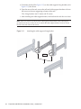
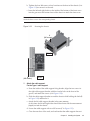
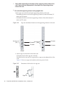
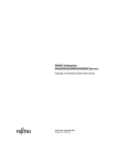
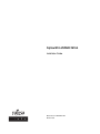
Figure 2-10 shows the cutoff characteristics of the circuit breaker.
Use a breaker with cutoff characteristics that have a Long-time delay type equivalent
to cutoff characteristic D (IEC/EN60898 or DIN VDE 0641 part II) shown in Figure
2-10, or one with longer cutoff characteristics.
30
Fujitsu M10-4/SPARC M10-4 Installation Guide ・ October 2015
Figure 2-10 Distribution panel breaker characteristics on the equipment side
180
120
60
40
20
Minute
10
6
4
2
Operating time
1
40
20
10
6
4
2
1
Second 0.6
0.4
0.2
B
C
D
0.1
0.06
0.04
0.02
0.01
1
1.5 2
3
4 5 6 7 8 10
15 20
30 40 50
80 100
Current (Scaling factor against rated current)
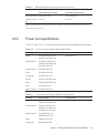
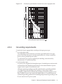
2.9.4
Grounding requirements
Ground each chassis appropriately according to the input power type.
■
For single-phase input
The components of each chassis do not include a grounded (three-wire type)
power cord. Order the power cords that match the device. Always connect the
power cords to grounded power outlets.
To confirm the type of power supplied by the building, contact the facility
administrator or a certified electrician.
■
For three-phase input
No power cord is supplied for three-phase input. Grounded power cords must be
connected from the distribution panel directly to the terminal boards of power
supply chassis as part of local electrical work.
Although common grounding is possible with this device, grounding methods
vary depending on the building of the installation. When using common
grounding, ground devices such that the grounding resistance is equal to or less
than 10 ohms. Be sure to have the facility administrator or a certified electrician
confirm the grounding method for the building and perform the grounding work.
Do not connect to an IT power system.
Chapter 2 Planning and Preparing for System Installation
31
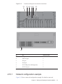
2.10
Checking External Interface Port
Specifications
This section provides an overview of the specifications of the external interface ports
required in installation and operation of the SPARC M10-4.
You can use the following external interface ports on the SPARC M10-4.
XSCF unit administration port
■
■
Serial port
The eXtended System Control Facility (XSCF) has one RS-232C-compliant serial
port. You can monitor and control the system by connecting the system
management terminal to the serial port. Functions that require TCP/IP are not
available through the serial port.
XSCF-LAN port
In addition to the serial port, the XSCF has two 1000BASE-T LAN ports. You can
remotely monitor and control the system by configuring a system control network
using a LAN port. There are two types of interfaces available: a command-line
interface (XSCF shell) and a browser user interface (XSCF Web).
Do not make a connection with a network switch or hub until you complete the
network setting for the XSCF. If a connection is made before the completion of the
setting, devices connecting with others may become unable to communicate, or
unauthorized login by a malicious third party to the XSCF of this chassis may be
unable to be prevented.
■
XSCF USB port (for field engineers)
Field engineers use this port to download information from the XSCF.
Other unit ports
■
GbE LAN port
The port is used to connect Oracle Solaris to the network. There are four ports.
Connection to the network is also possible through a LAN card, which is provided
by the customer, mounted in a PCI Express (PCle) slot.
■
■
SAS port
This port is used to connect an external SAS device.
USB port
This is a general-purpose USB port. Use the port to connect an external USB DVD
device, etc.
Figure 2-11 shows locations of external interface ports on the SPARC M10-4.
32
Fujitsu M10-4/SPARC M10-4 Installation Guide ・ October 2015
Figure 2-11 Locations of the ports for network connections
(3)
(5) (4) (1) (6)
(2)
(7)
2.10.1
No.
Port
Number on board
1, 7
USB port
2
2
GbE LAN port
4
3
SAS port
1
4
Serial port
1
5
XSCF USB port (for field engineers)
1
6
XSCF-LAN port
2
Network configuration example
Figure 2-12 shows a network configuration example. For details on network
Chapter 2 Planning and Preparing for System Installation
33
connections, see "1.3 Network Configuration" in the Fujitsu M10/SPARC M10
Systems System Operation and Administration Guide.
Figure 2-12 Network configuration example
Serial port
RJ45
XSCF LAN port
RJ45
GbE LAN port
RJ45
Internet
RS-232C serial
cross cable
34
Fujitsu M10-4/SPARC M10-4 Installation Guide ・ October 2015
Terminal
Chapter 3
Installing the System
This chapter describes the work of preparing for installation, mounting a chassis in a
rack, and mounting optional components.
■
Preparing the Necessary Tools/Information for Installation
3.1
■
Confirming Delivered Components
■
Mounting the Chassis in a Rack
■
Mounting Optional Components
Preparing the Necessary Tools/
Information for Installation
This section describes the tools and information that are required in installation.
Have these prepared before starting installation work.
Table 3-1 List of necessary tools
Name
Use
Phillips screwdriver (#2)
Used to attach cable support brackets and mount
optional components
Phillips screwdriver (#3)
Used to attach rails to the rack supporting columns
ESD mat and antistatic wrist strap
Used in the work of mounting optional components
Lifter
(hydraulic or mechanical jack)
Used in the work of mounting chassis in racks
System management terminal
(ASCII terminal, workstation, terminal server, patch
panel connected to terminal server, etc.)
Used to connect to the XSCF and for the work of
checking and configuring the XSCF firmware
35
3.2
Confirming Delivered Components
Here, confirm delivered components by referring to the List of Attachments that
comes with the chassis. If any item is missing, incorrect, or damaged, contact the
retailer from which the product was purchased or a sales representative.
■
Confirming the delivered components of the SPARC M10-4
■
3.2.1
Confirming the delivered components of the PCI expansion unit
Confirming the delivered components of the
SPARC M10-4
This section describes the confirmation of delivered components of the SPARC M10-4.
1. Confirm the delivered components by referring to the List of Attachments that
comes with the SPARC M10-4.
Table 3-2 below is a list of accessories for the SPARC M10-4. The accessories may
change without notice.
Table 3-2 Reference: List of accessories for the chassis
Name
Quantity
Remarks
SPARC M10-4 chassis
1
Fujitsu M10/SPARC M10 Systems Getting Started Guide
(*)
1
Fujitsu M10/SPARC M10 Systems Important Legal and
Safety Information
1
CPU Activation CD-ROM
1
(*1)
Power cord
2
For 200 VAC (*2)
Serial cable
1
Rack mount kit
1 set
Cable support
1 set
*1 The disk contains the CPU Activation key information.
*2 The power cord is ordered separately (required option), so it may not come with the product.
2.
36
Check for incomplete engagement, incomplete contact, or looseness in the
mounting of an internal disk that may have been caused by vibration during
transportation or moving of the equipment.
Also confirm that the PCI cassette lever is locked at the top.
Fujitsu M10-4/SPARC M10-4 Installation Guide ・ October 2015
3.2.2
Confirming the delivered components of the PCI
expansion unit
This section describes the confirmation of delivered components of the PCI
expansion unit.
1. Confirm the delivered components by referring to the List of Attachments that
comes with the PCI expansion unit.
Table 3-3 below is a list of accessories for the PCI expansion unit. The accessories
may change without notice.
Table 3-3 Reference: List of accessories for the PCI expansion unit
Name
Quantity
PCI expansion unit
1
Power cord
2
For 100 VAC or 200 VAC (*1)
Core
2
Used when attached to power cord
Rack mount kit
1 set
Cable support
1 set
Link cable (optical, 10 m)
Remarks
2
Either of two types of cables is selected (*2)
Management cable
1
(*2)
Link card
1
Card for mounting in the SPARC M10-4 chassis (*3)
Link cable (electrical, 3 m)
*1 The power cord is ordered separately (required option), so it may not come with the product.
*2 If ordered at the same time as the SPARC M10-4, the cable is supplied with the SPARC M10-4.
*3 If ordered at the same time as the SPARC M10-4, the card is shipped mounted in the SPARC M10-4.
2.
3.3
Confirm that the PCIe card cassette lever is locked at the bottom.
Mounting the Chassis in a Rack
This section describes the procedures for mounting the chassis in an equipment rack.
The method of securing the rails differs depending on the rack type. As described in
this section, the methods of securing them differ between the racks with supporting
columns having angled holes and the racks with supporting columns having M6
screw holes.
For rack details, see the manual for the rack used.
If the chassis has already been mounted in the rack, go to "3.4 Mounting Optional
Components."
For the rack mounting procedure of each chassis, see the following sections:
■
Mounting the SPARC M10-4 in a rack
Chapter 3 Installing the System
37
■
3.3.1
Mounting the PCI expansion unit in a rack
Mounting the SPARC M10-4 in a rack
1.
Confirm that the rack mount kit supplied with the SPARC M10-4 is complete.
Note - The rack mount kit contains two types of cable support: Type-1 and Type-2. The
Type-2 cable support is an integrated unit consisting of the parts indicated by numbers 2 to 5
in Figure 3-1. Steps 7 and 11 in the mounting procedure vary depending on the shape of the
cable support. Attach the support according to the corresponding steps.
Figure 3-1 Rack mount kit
38
Fujitsu M10-4/SPARC M10-4 Installation Guide ・ October 2015
Number
in figure
Name
Quantity
Remarks
1
Rail
2
Bilaterally symmetrical
shape
2
Cable support (*1) (*2)
1
3
Cable support bracket (*2)
2
4
M3 screw (*2)
2
5
Cable support fixing bracket (*2)
2
6
M6 screw
10
7
Cage nut
10
Bilaterally symmetrical
shape
Bilaterally symmetrical
shape
*1 There are two types of cable support: Type-1 and Type-2. To distinguish between them, see Figure 3-2.
*2 The Type-2 cable support is an integrated unit consisting of these parts.
Figure 3-2 Type-2 cable support
New
Reference: Old
2.
Confirm that the rack is fixed in place to prevent the rack from toppling over.
3.
Confirm the chassis mounting location in the rack. If necessary, mark the
location on the supporting columns.
4.
Step 4 differs depending on the shape of the supporting column holes of the
rack. Perform the work appropriate to the shape of the supporting column
holes of the rack.
■
For racks with supporting columns having angled holes
Attach cage nuts to the left and right supporting columns of the rack.
- Attachment locations in the front supporting columns: (From the bottom) 1U
center, 2U bottom, and 3U top
- Attachment locations in the rear supporting columns: (From the bottom) 1U
center and 2U center
Chapter 3 Installing the System
39
Figure 3-3 Cage nut attachment locations in the supporting columns of the rack
4U
Mounting
area (4U)
3U top
3U
Mounting
area (4U)
2U
2U center
2U bottom
1U
1U center
FRONT
1U center
REAR
a. Attach cage nuts from the inside of the rack.
Orient the hooks of the cage nut vertically.
Hook the hook at one end of a cage nut into a cage nut attachment hole of the
rack.
Figure 3-4 shows a cage nut hooked on the lower part of a hole.
Figure 3-4 Orientation of the hooks of a cage nut
Cage nut
b. Insert the hook at the tip of the supplied cage nut attachment tool through a
cage nut attachment hole from the front, and engage it with the hook at the
other end of the cage nut.
40
Fujitsu M10-4/SPARC M10-4 Installation Guide ・ October 2015
Figure 3-5 Using the cage nut attachment tool
Direction of
tool hook tip
Cage nut attachment tool
c. Pull the tool forward to attach the cage nut.
Push in direction A while simultaneously pulling in direction B as shown in
Figure 3-6.
Figure 3-6 Attaching a cage nut
B
A
Completed view
■
For supporting columns with M6 screw holes
Remove the pins at the front and rear of the rail.
a. Remove the screw (A in Figure 3-7) securing the rail pin.
b. Remove the pin (B in Figure 3-7).
c. Remove pins from the left and right rails in the same manner.
d. Store the removed pins and screws (eight pins and eight screws in total) for
future use when the chassis is moved.
Chapter 3 Installing the System
41
Figure 3-7 Removing a rail pin
A
5.
B
Remove the one screw (A in Figure 3-8) from the side of the rail.
The removed screw will be used in step 8.
Figure 3-8 Screws on the sides of rails
A
A
B
C
FRONT
6.
FRONT
Attach the rail to the rack.
Attach the rail such that the spring-loaded side (B in Figure 3-8) faces the front
and the flange (C in Figure 3-8) faces the bottom.
a. From the front of the rack, insert the rail protrusions into 2U top and 1U top
in the front supporting column of the rack.
b. Pull out the rail to as far as the depth of the rack.
c. Insert the rail protrusions into 2U top and 1U bottom in the rear supporting
column of the rack.
d. Secure the rail with one M6 screw to the front supporting column of the rack.
The fixing location is 2U bottom.
e. Attach the other rail in the same manner.
42
Fujitsu M10-4/SPARC M10-4 Installation Guide ・ October 2015
Note - After removing its screw, hold the rail level with both hands. If the rail tilts, it may
stretch.
Figure 3-9 Attaching the rail: Locations of protrusions
Mounting
area (4U)
Mounting
area (4U)
2U top
1U top
1U bottom
FRONT
REAR
Figure 3-10 Attaching the rail: Fixing location of the screw
REAR
2U bottom
FRONT
FRONT
7.
Attach the cable support fixing brackets to the rear supporting columns of the
rack.
For the Type-1 cable support
Chapter 3 Installing the System
43
a. Orient the notches (B in Figure 3-11) on the cable support fixing brackets (A in
Figure 3-11) face down.
b. From the rear of the rack, secure the rails and cable support brackets with two
M6 screws to the rear supporting columns of the rack.
The fixing locations are 1U center and 2U center.
c. After attaching the cable support bracket, confirm that the rack door can close.
Note - If the door cannot close because the cable support fixing bracket or the cable support
protrudes from the rear of the rack, do not attach the cable support bracket. However, secure
the rail to the rack with two M6 screws.
Figure 3-11 Attaching the cable support fixing bracket
REAR
B
A
B
44
Fujitsu M10-4/SPARC M10-4 Installation Guide ・ October 2015
Figure 3-12 Securing the cable support fixing brackets and the rails
Mounting
area (4U)
2U center
1U center
REAR
For the Type-2 cable support
a. Loosen the four screws (C in Figure 3-13) from the inside of the cable support.
Figure 3-13 Removing the cable support fixing brackets (1)
C
b. Slide the cable support fixing brackets (D in Figure 3-14) to remove them.
Chapter 3 Installing the System
45
Figure 3-14 Removing the cable support fixing brackets (2)
D
c. From the rear of the rack, secure the rails and cable support fixing brackets
(D) with two M6 screws to the rear supporting columns of the rack.
The fixing locations are 1U center and 2U center.
Figure 3-15 Attaching the cable support brackets
REAR
D
46
Fujitsu M10-4/SPARC M10-4 Installation Guide ・ October 2015
Figure 3-16 Securing the cable support fixing brackets and the rails
Mounting area
(4U)
2U center
1U center
REAR
d. After attaching the cable support fixing brackets, confirm that the rack door
can close.
Note - If the door cannot close because the cable support fixing bracket or the cable support
protrudes from the rear of the rack, do not attach the cable support bracket. However, secure
the rail to the rack with two M6 screws.
8.
Secure the rail sides by using the screws (M5) removed in step 5 (A in Figure
3-17).
Figure 3-17 Securing the sides of rails with screws
REAR
A (M5 screws)
FRONT
9.
Mount the chassis in the rack.
Mount the chassis from the front of the rack.
Chapter 3 Installing the System
47
Note - The SPARC M10-4 weighs 60 kg. Mount the chassis in the rack with four or
more people working together. Alternatively, use a lifter such as a hydraulic or
mechanical jack.
a. When using a lifter, secure it horizontally.
b. Lift the chassis to the mounting location with the lifter or with human force.
c. Put the rear part of the chassis on the flanges of the rails.
d. Slide the chassis into the rack. At this time, store the handle on the side of the
chassis. Also, confirm that the guide pins of the chassis (A in Figure 3-18) fit
into their rail guides (B in Figure 3-18).
e. Insert the chassis all the way to store it inside the rack.
Figure 3-18 Mounting in the rack
C
A
FRONT
B
A
FRONT
10. Secure the chassis to the rack.
a. Push out the left and right slide locks on the front cover (C in Figure 3-18) to
release the locks, and remove the front cover.
48
Fujitsu M10-4/SPARC M10-4 Installation Guide ・ October 2015
b. Tighten the four M6 screws at four locations on the front of the chassis (A in
Figure 3-19) to secure it to the rack.
c. Insert the left and right hooks on the inside of the bottom of the front cover
into the grooves at the bottom front of the chassis to attach the front cover.
Note - A label with the serial number of the chassis is affixed to the front cover. Be sure to
attach the front cover to the corresponding chassis.
Figure 3-19 Securing the chassis
A
(M6 screws)
FRONT
A
(M6 screws)
FRONT
11. Attach the cable support.
For the Type-1 cable support
a. From the inside of the cable support fixing bracket, align the two screws in
the right cable support bracket with the circular holes at the front of the
groove, and attach the screws (A in Figure 3-20).
b. Slide the cable support bracket toward the chassis while holding the latch (B
in Figure 3-20) attached to it.
c. Attach the left cable support bracket in the same manner.
At this time, the left and right sides should have been slid the same amount
(depth) toward the chassis.
d. Secure the cable support with two M3 screws (C in Figure 3-21).
e. Close the rear door of the rack, and confirm that the cable support does not
Chapter 3 Installing the System
49
interfere. If it interferes, slide the cable support toward the chassis while
holding the latches (B in Figure 3-20) of the left and right cable support
brackets. The cable support should be in the position nearest the chassis, with
the cable support bracket latches engaged.
f. If the cable support interferes with the door even when you slide it toward the
chassis as far as possible, remove the cable support.
Figure 3-20 Attaching the cable support brackets
REAR
Screw
A
Circular hole sections
B
50
Fujitsu M10-4/SPARC M10-4 Installation Guide ・ October 2015
Figure 3-21 Attaching the cable support
REAR
C
(M3 screws)
For the Type-2 cable support
a. Tilt the cable support to align the circular holes at the rear of the groove with
the two screws of a cable support fixing bracket (D in Figure 3-22), and attach
it. Level the cable support. Then, align the circular holes at the other side with
the two screws, and attach it.
Figure 3-22 Attaching the cable support (1)
D
Circular hole
sections
REAR
Chapter 3 Installing the System
51
b. Slide in the cable support all the way, and tighten the four screws (C in Figure
3-23).
Figure 3-23 Attaching the cable support (2)
C
REAR
Note - If the dimension between the front and rear columns of the rack is less than 740 mm,
secure the cable support without sliding it in all the way. The fixing location varies
depending on the dimension between the front and rear columns of the rack. Based on
Figure 3-24, align the scale marks (E in Figure 3-24) (spacing: 10 mm) on the cable support
with the screws (F in Figure 3-24) of the fixing brackets to secure the cable support.
Figure 3-24 Attaching the cable support (3)
Scale position 1st
Scale Scale position 10th
position 6th
E
REAR
F
Table 3-4 Dimensions between the front and rear columns and scale positions
52
Dimension between front and rear columns (mm)
Scale position
740
1st
Fujitsu M10-4/SPARC M10-4 Installation Guide ・ October 2015
Table 3-4 Dimensions between the front and rear columns and scale positions (continued)
Dimension between front and rear columns (mm)
Scale position
730
2nd
720
3rd
710
4th
700
5th
690
6th
680
7th
670
8th
660
9th
650
10th
Note - If you have difficulty laying a thick cable into the cable support, move forward the
fixing location of the cable support to make the work easier.
c. Close the rear door of the rack, and confirm that the cable support does not
interfere. If the cable support interferes with the rear door, remove the cable
support. Even if you remove the cable support, leave the rails secured with
the two M6 screws to the rack.
Figure 3-25 Completed SPARC M10-4 configuration
3.3.2
Mounting the PCI expansion unit in a rack
1.
Confirm that the rack mount kit supplied with the PCI expansion unit is
complete.
Chapter 3 Installing the System
53
Note - The rack mount kit contains two types of cable support: Type-1 and Type-2. To
distinguish the Type-2 cable support, see Figure 3-27. The Type-2 cable support is an
integrated unit consisting of the parts indicated by numbers 2 to 5 in Figure 3-26. Steps 6 and
10 in the mounting procedure vary depending on the shape of the cable support. Attach the
support according to the corresponding steps.
Note - The rack mount kit contains two types of rails: Type-1 and Type-2. To distinguish the
Type-2 rail, see Figure 3-28. The mounting procedure varies depending on the shape of the
rail. The text describes corresponding procedures, so attach the rail according to the relevant
procedure.
Figure 3-26 Rack mount kit
54
Fujitsu M10-4/SPARC M10-4 Installation Guide ・ October 2015
Number
in figure
Name
Quantity
Remarks
1
Rail
2
Bilaterally symmetrical
shape
2
Cable support (*1) (*2)
1
3
Cable support bracket (*2)
2
4
M3 screw (*2)
2
5
Cable support fixing bracket (*2)
2
6
M6 screw
10
7
Cage nut
10
Bilaterally symmetrical
shape
Bilaterally symmetrical
shape
*1 There are two types of cable support: Type-1 and Type-2. To distinguish between them, see Figure 3-27.
*2 The Type-2 cable support is an integrated unit consisting of these parts.
Figure 3-27 Type-2 cable support
New
Reference: Old
Figure 3-28 Type-2 rail
New
(Dedicated to PCI
expansion unit)
2.
Reference: Old
Confirm that the rack is fixed in place to prevent the rack from toppling over.
Chapter 3 Installing the System
55
3.
■
Step 3 differs depending on the shape of the supporting column holes of the
rack. Perform the work appropriate to the shape of the supporting column
holes of the rack.
For racks with supporting columns having angled holes
Attach cage nuts to the left and right supporting columns of the rack.
- Attachment locations in the front supporting columns: (From the bottom) 1U
center and 2U bottom
- Attachment locations in the rear supporting columns: (From the bottom) 1U
center and 2U center
Figure 3-29 Cage nut attachment locations in the supporting columns of the rack
㪤㫆㫌㫅㫋㫀㫅㪾㩷㪸㫉㪼㪸
(2U)
2U
1U
㪤㫆㫌㫅㫋㫀㫅㪾㩷㪸㫉㪼㪸
2U bottom
(2U)
2U center
1U center
1U center
FRONT
REAR
a. Attach cage nuts from the inside of the rack.
Orient the hooks of the cage nut vertically.
Hook the hook at one end of a cage nut into a cage nut attachment hole of the
rack.
Figure 3-30 shows a cage nut hooked on the lower part of a hole.
Figure 3-30 Orientation of the hooks of a cage nut
Cage nut
56
Fujitsu M10-4/SPARC M10-4 Installation Guide ・ October 2015
b. Insert the hook at the tip of the supplied cage nut attachment tool through a
cage nut attachment hole from the front, and engage it with the hook at the
other end of the cage nut.
Figure 3-31 Using the cage nut attachment tool
Direction of
tool hook tip
Cage nut attachment tool
c. Pull the tool forward to attach the cage nut.
Push in direction A while simultaneously pulling in direction B as shown in
Figure 3-32.
Figure 3-32 Attaching a cage nut
B
A
Completed view
■
For supporting columns with M6 screw holes
For the Type-1 rail
Remove the pins at the front and rear of the rail.
a. Remove the screw (A in Figure 3-33) securing the rail pin.
b. Remove the pin (B in Figure 3-33).
c. Remove pins from the left and right rails in the same manner.
d. Store the removed pins and screws (eight pins and eight screws in total) for
future use when the chassis is moved.
Chapter 3 Installing the System
57
Figure 3-33 Removing pins from the Type-1 rail
A
B
For the Type-2 rail
Remove the pins at the front and rear of the rail.
a. Remove the pins (A in Figure 3-34) at the front and rear of the left and right
rails.
b. Store the removed pins (four pins in total) for future use when the chassis is
moved.
Figure 3-34 Removing pins from the Type-2 rail
A
4.
Remove each screw from the side of the rail.
For the Type-1 rail, remove the one screw (A in Figure 3-35) from the side of the
rail.
For the Type-2 rail, loosen the two screws (B in Figure 3-36) from the side of the
rail.
58
Fujitsu M10-4/SPARC M10-4 Installation Guide ・ October 2015
Note - After removing or loosening the screw or screws, hold the rail level with both hands.
If the rail tilts, it may stretch.
Figure 3-35 Screw on the side of the Type-1 rail
A
A
B
C
FRONT
FRONT
Figure 3-36 Screws on the side of the Type-2 rail
B
FRONT
5.
B
FRONT
Attach the rail to the rack.
Note - After removing its screw, hold the rail level with both hands. If the rail tilts, it may
stretch.
For the Type-1 rail
Chapter 3 Installing the System
59
Attach the rail such that the spring-loaded side (B in Figure 3-35) faces the front
and the flange (C in Figure 3-35) faces the bottom.
a. From the front of the rack, insert the rail protrusions into 2U top and 1U top
in the front supporting column of the rack.
b. Pull out the rail to as far as the depth of the rack.
c. Insert the rail protrusions into 2U top and 1U bottom in the rear supporting
column of the rack.
d. Secure the rail with one M6 screw to the front supporting column of the rack.
The fixing location is 2U bottom.
e. Attach the other rail in the same manner.
Figure 3-37 Attaching the Type-1 rail: Locations of protrusions
2U top
Mounting
area (2U)
Mounting
area (2U)
1U top
1U bottom
FRONT
REAR
For the Type-2 rail
The letter [R] on a side of a rail indicates that the side is the front right side, and
[L] indicates that the side is the front left side.
a. From the rear of the rack, insert the rail protrusion into 1U top in the front
supporting column of the rack.
b. Pull out the rail to as far as the depth of the rack.
c. Insert the rail protrusion into 2U top in the rear supporting column of the
rack.
d. Secure the rail with one M6 screw to the front supporting column of the rack.
The fixing location is 2U bottom.
e. Attach the other rail in the same manner.
60
Fujitsu M10-4/SPARC M10-4 Installation Guide ・ October 2015
Figure 3-38 Attaching the Type-2 rail: Locations of protrusions
2U top
Mounting area
(2U)
Mounting area
(2U)
1U top
FRONT
REAR
Figure 3-39 Attaching the rail: Fixing location of the screw
REAR
2U bottom
FRONT
FRONT
6.
Attach the cable support fixing brackets to the rear supporting columns of the
rack.
For the Type-1 cable support
a. Orient the notches (B in Figure 3-40) on the cable support fixing brackets (A in
Figure 3-40) face down.
b. From the rear of the rack, secure the rails and cable support brackets with two
M6 screws to the rear supporting columns of the rack.
Chapter 3 Installing the System
61
The fixing locations are 1U center and 2U center.
c. After attaching the cable support bracket, confirm that the rack door can close.
Note - If the door cannot close because the cable support fixing bracket or the cable support
protrudes from the rear of the rack, do not attach the cable support bracket. However, secure
the rail to the rack with two M6 screws.
Figure 3-40 Attaching the cable support fixing bracket
REAR
B
A
B
62
Fujitsu M10-4/SPARC M10-4 Installation Guide ・ October 2015
Figure 3-41 Securing the cable support fixing brackets and the rails
2U center
Mounting
area (2U)
1U center
REAR
For the Type-2 cable support
a. Loosen the four screws (C in Figure 3-42) from the inside of the cable support.
Figure 3-42 Removing the cable support fixing brackets (1)
C
b. Slide the cable support fixing brackets (D in Figure 3-43) to remove them.
Chapter 3 Installing the System
63
Figure 3-43 Removing the cable support fixing brackets (2)
D
c. From the rear of the rack, secure the rails and cable support fixing brackets
(D) with two M6 screws to the rear supporting columns of the rack.
The fixing locations are 1U center and 2U center.
Figure 3-44 Attaching the cable support brackets
REAR
D
64
Fujitsu M10-4/SPARC M10-4 Installation Guide ・ October 2015
Figure 3-45 Securing the cable support fixing brackets and the rails
2U center
Mounting
area (2U)
1U center
REAR
d. After attaching the cable support fixing brackets, confirm that the rack door
can close.
Note - If the door cannot close because the cable support fixing bracket or the cable support
protrudes from the rear of the rack, do not attach the cable support bracket. However, secure
the rail to the rack with two M6 screws.
7.
Secure the rail sides by using the screws (M5) removed in step 4 (A in Figure
3-46).
Figure 3-46 Securing the sides of rails with screws
REAR
A (M5 screws)
FRONT
8.
Mount the PCI expansion unit in the rack.
Chapter 3 Installing the System
65
Mount the chassis from the front of the rack.
Caution - The PCI expansion unit weighs 22 kg. Exercise thorough caution when
mounting it in the rack.
Note - Mount the PCI expansion unit in the rack with two or more people working together.
Alternatively, use a lifter.
a. When using a lifter, secure it horizontally.
b. Lift the chassis to the mounting location with the lifter or with human force.
c. Put the rear part of the chassis on the flanges of the rails.
d. Slide the PCI expansion unit into the rack. At this time, confirm that the PCI
expansion unit sits on the rails and that the guide pins of the PCI expansion
unit (A in Figure 3-47) fit into their rail guides (B in Figure 3-47).
e. Insert the PCI expansion unit all the way to store it inside the rack.
66
Fujitsu M10-4/SPARC M10-4 Installation Guide ・ October 2015
Figure 3-47 Mounting in the rack
A
C
FRONT
B
A
FRONT
9.
Secure the PCI expansion unit in the rack.
a. Push out the left and right slide locks on the front cover (C in Figure 3-47) to
release the locks, and remove the front cover.
b. Tighten the two M6 screws at two locations on the front of the PCI expansion
unit (A in Figure 3-48) to secure it to the rack.
c. Insert the left and right hooks on the inside of the bottom of the front cover
into the grooves at the bottom front of the PCI expansion unit to attach the
front cover.
Note - A label with the serial number of the PCI expansion unit is affixed to the front cover.
Be sure to attach the front cover to the corresponding chassis.
Chapter 3 Installing the System
67
Figure 3-48 Securing the PCI expansion unit
A
A
10. Attach the cable support.
For the Type-1 cable support
a. From the inside of the cable support fixing bracket, align the two screws in
the right cable support bracket with the circular holes at the front of the
groove, and attach the screws (A in Figure 3-49).
b. Slide the cable support bracket toward the chassis while holding the latch (B
in Figure 3-49) attached to it.
c. Attach the left cable support bracket in the same manner. At this time, the left
and right sides should have been slid the same amount (depth) toward the
chassis.
d. Secure the cable support with two M3 screws (C in Figure 3-50).
e. Close the rear door of the rack, and confirm that the cable support brackets do
not interfere. If it interferes, slide the cable support toward the chassis while
holding the latches (B in Figure 3-49) of the left and right cable support
brackets. The cable support should be in the position nearest the chassis, with
the cable support bracket latches engaged.
f. If the cable support interferes with the door even when you slide it toward the
chassis as far as possible, remove the cable support.
68
Fujitsu M10-4/SPARC M10-4 Installation Guide ・ October 2015
Figure 3-49 Attaching the cable support brackets
REAR
Screw
A
Circular hole sections
B
Chapter 3 Installing the System
69
Figure 3-50 Attaching the cable support
REAR
C
(M3 screws)
For the Type-2 cable support
a. Tilt the cable support to align the circular holes at the rear of the groove with
the two screws of a cable support fixing bracket (D in Figure 3-51), and attach
it. Level the cable support. Then, align the circular holes at the other side with
the two screws, and attach it.
Figure 3-51 Attaching the cable support (1)
D
Circular
hole sections
70
Fujitsu M10-4/SPARC M10-4 Installation Guide ・ October 2015
REAR
b. Slide in the cable support all the way, and tighten the four screws (C in Figure
3-52).
Figure 3-52 Attaching the cable support (2)
C
REAR
Note - If the dimension between the front and rear columns of the rack is less than 740 mm,
secure the cable support without sliding it in all the way. The fixing location varies
depending on the dimension between the front and rear columns of the rack. Based on
Figure 3-53, align the scale marks (E in Figure 3-53) (spacing: 10 mm) on the cable support
with the screws (F in Figure 3-53) of the fixing brackets to secure the cable support.
Figure 3-53 Attaching the cable support (3)
Scale position 1st
Scale position 10th
Scale
position 6th
E
REAR
F
Table 3-5 Dimensions between the front and rear columns and scale positions
Dimension between front and rear columns (mm)
Scale position
740
1st
Chapter 3 Installing the System
71
Table 3-5 Dimensions between the front and rear columns and scale positions (continued)
Dimension between front and rear columns (mm)
Scale position
730
2nd
720
3rd
710
4th
700
5th
690
6th
680
7th
670
8th
660
9th
650
10th
Note - If you have difficulty laying a thick cable into the cable support, move forward the
fixing location of the cable support to make the work easier.
c. Close the rear door of the rack, and confirm that the cable support does not
interfere. If the cable support interferes with the rear door, remove the cable
support. Even if you remove the cable support, leave the rails secured with
the two M6 screws to the rack.
Figure 3-54 Completed cable support attachment
72
Fujitsu M10-4/SPARC M10-4 Installation Guide ・ October 2015
Figure 3-55 Completed PCI expansion unit configuration
3.4
Mounting Optional Components
This section describes the procedures for mounting optional components such as
memory and PCIe cards.
If the optional components are ordered together with the chassis, they are shipped
mounted in the chassis. If the optional components are ordered separately, they will
need to be mounted on site. Mount optional components after mounting the chassis
in the rack.
■
Mounting optional components in the SPARC M10-4
■
3.4.1
Mounting optional components in the PCI expansion unit
Mounting optional components in the SPARC
M10-4
The following table lists the optional components and references for the SPARC
M10-4. For detailed procedures, see the Fujitsu M10-4/Fujitsu M10-4S/SPARC
M10-4/SPARC M10-4S Service Manual, and perform work accordingly. All the
references in the table can be found in the Fujitsu M10-4/Fujitsu M10-4S/SPARC
M10-4/SPARC M10-4S Service Manual.
Chapter 3 Installing the System
73
Table 3-6 List of optional components and references for the SPARC M10-4
3.4.2
Optional component name
Reference
Memory
"Chapter 9
Hard disk drive
"Chapter 10
PCIe card
Link card
"Chapter 8
Maintaining the CPU Memory Unit/Memory"
Maintaining the Internal Disks"
Maintaining the PCI Express Cards"
Mounting optional components in the PCI
expansion unit
The following table lists the optional components and references for the PCI
expansion unit. For detailed procedures, see the PCI Expansion Unit for Fujitsu
M10/SPARC M10 Systems Service Manual, and perform work accordingly. All the
references in the table can be found in the PCI Expansion Unit for Fujitsu M10/SPARC
M10 Systems Service Manual.
Table 3-7 List of optional components and references for the PCI expansion unit
74
Optional component name
Reference
PCIe card
"Chapter 8
Cards"
Fujitsu M10-4/SPARC M10-4 Installation Guide ・ October 2015
Maintaining the PCI Express
Chapter 4
Connecting Cables to the Chassis
This chapter describes the procedure for connecting the power cords, serial cable,
and network cables to each chassis. All ports for the connections are on the rear of the
chassis. For a description of each port, see "2.10 Checking External Interface Port
Specifications."
■
Connecting Cables to the SPARC M10-4
■
4.1
Connecting Cables to the PCI Expansion Unit
Connecting Cables to the SPARC
M10-4
This section describes the procedure for connecting the serial cable, network cables,
and power cords to the SPARC M10-4.
1. Connect the serial cable supplied with the chassis from the serial port of the
XSCF unit (A in Figure 4-1) to the system management terminal.
75
Figure 4-1 Serial port location
A
2.
Connect a LAN cable of Category 5 or higher from a GbE port (A in Figure 4-2)
to the network switch or hub.
The GbE ports are used for the user network. Connect the other servers, other
PCs, UPS, etc. that are necessary for business via the network switch or hub.
Figure 4-2 GbE port locations
A
76
3.
If a PCIe card is mounted, connect a LAN cable and I/O cable to the respective
ports on the PCIe card.
4.
Secure the cables to the cable support.
While leaving extra length, secure the cables connected to the PCIe card to the
cable support.
5.
Connect the supplied power cords to the power supply units (A in Figure 4-3).
Secure the power cords with a power clamp.
Fujitsu M10-4/SPARC M10-4 Installation Guide ・ October 2015
Figure 4-3 Power supply unit locations
A
Note - Do not connect to an outlet at this point.
4.2
Connecting Cables to the PCI
Expansion Unit
This section describes the procedure for connecting the management cable, link
cables, and power cords to the PCI expansion unit.
1. Connect the management cable.
Connect the link board of the PCI expansion unit and the link card of the chassis
by using the management cable. (See A inFigure 4-5, and A inFigure 4-6.)
2.
Connect link cables.
Connect the cables such that the port indications on the link card and link board
match the labels on the cables.
Each port on the link card and link board is color-coded and numbered. Connect
the port to the corresponding port of the same color and number.
Note - The two link cables are the same. The labels on both ends of each cable have the same
indications. When laying the cables, check their connections to confirm that the ends of the
cables connected to the link card and link board are at the same locations as shown on the
labels.
Chapter 4 Connecting Cables to the Chassis
77
Figure 4-4 Link cable (optical) shape
a. Connect one end of a link cable to the port (B in Figure 4-5) on the link board
of the PCI expansion unit.
b. Connect the other end to the port (B in Figure 4-6) on the link card of the
SPARC M10-4. c. Connect one end of the other link cable to the port (C in Figure 4-5) on the link
board of the PCI expansion unit.
d. Connect the other end to the port (C in Figure 4-6) on the link card of the
SPARC M10-4.
Note - The two ports have the same shape and so may be incorrectly connected. Check the
labels at both ends of each cable to confirm that the cable is connected to the correct ports.
Hold the connector of the link cable (electrical) or link cable (optical), and insert it straight
into the opening. Do not hold the cable or its tab part when inserting it.
Note - PCI cassettes are mounted upside down in the SPARC M10-4 and the PCI expansion
unit. Accordingly, the port locations of PCIe cards, including the link card, are also upside
down. Be careful about this when mounting the cables.
Figure 4-5 Connecting the link cables and management cable (PCI expansion unit
side)
C
B
A
78
Fujitsu M10-4/SPARC M10-4 Installation Guide ・ October 2015
Figure 4-6 Connecting the link cables and management cable (SPARC M10-4
side)
A
B
C
3.
If a PCIe card is mounted, connect a LAN cable and I/O cable to the respective
ports on the PCIe card.
4.
Secure the cables to the cable support.
While leaving extra length, secure the cables connected to the PCIe card to the
cable support.
5.
Attach a core to each supplied power cord, and connect the cord to a power
supply unit.
a. Insert the power cord so that it fits into the groove of the core. Pinch the core
closed until its latch is secured.
Attach the core at a location 90 mm (3.5 in) from the end of the power cord
connector. (See Figure 4-7)
b. Connect the power cord to the power supply unit (A in Figure 4-8).
Secure the power cords with a power clamp.
Figure 4-7 Core attachment location
90 mm (3.5 in)
Chapter 4 Connecting Cables to the Chassis
79
Figure 4-8 Power supply unit locations
A
Note - Do not connect to an outlet at this point.
80
Fujitsu M10-4/SPARC M10-4 Installation Guide ・ October 2015
Chapter 5
Performing an Initial System Diagnosis
This chapter describes the procedures for connecting the system management
terminal, turning on the input power, and checking components.
For details on the XSCF commands executed in each step, see the Fujitsu M10/SPARC
M10 Systems XSCF Reference Manual.
■
Connecting the System Management Terminal to the Chassis
5.1
■
Turning on the Input Power and Starting the XSCF
■
Logging In to the XSCF
■
Checking the XCP Version
■
Checking the Altitude Setting
■
Checking the Time Setting
■
Performing a Diagnosis Test
■
Checking the Component Status
Connecting the System Management
Terminal to the Chassis
This section describes the procedures for checking the terminal software settings of
the system management terminal and connecting the system management terminal
to the serial port of the XSCF unit.
1. Confirm that the terminal software for connecting the system management
terminal has the following setting values.
Table 5-1 Terminal software setting value
Setting item
Value
Baud rate
9600
Data length
8 bits
Parity
None
81
Table 5-1 Terminal software setting value (continued)
Setting item
Value
STOP bit
1 bit
Flow control
None
Delay
Other than 0
2.
5.2
Confirm that the system management terminal is connected to the serial port
of the chassis.
Turning on the Input Power and
Starting the XSCF
This section describes the procedures for connecting the power cords to outlets,
turning on the input power, and starting the XSCF.
1. Set the mode switch on the operation panel to the Service position.
The Service position is indicated by a wrench icon. The Locked position is
indicated by a lock icon.
Figure 5-1 Mode switch on the operation panel of the SPARC M10-4
Locked
Service
82
2.
Confirm that the power cord connector is connected to a power supply unit of
the chassis.
3.
Connect the power cord plug to an outlet.
If the outlet has a circuit breaker, turn on the circuit breaker switch.
Fujitsu M10-4/SPARC M10-4 Installation Guide ・ October 2015
4.
Check the XSCF unit LEDs.
a. The CHECK LED of the XSCF unit goes on for an instant immediately after
the input power is turned on.
b. The READY LED of the XSCF unit flashes during XSCF initialization and
stays on after the initialization completes.
Figure 5-2 Rear of the SPARC M10-4
5.3
Logging In to the XSCF
This section describes the procedure for logging in to the XSCF by using the default
XSCF user account.
Log in to the XSCF by using the default user account and authentication method until
a user account appropriate to the user environment is registered for you. The default
user privileges are useradm and platadm.
Remarks - platadm is mainly used to manage the whole system. useradm is mainly used to
manage user accounts. For details on the user privilege types and the privileges, see Table
6-3.
1.
After the system management terminal displays "SCF_READY", press the
[Enter] key.
2.
After the login prompt appears, enter "default" for the login name.
login: default
3.
After a message prompting operation of the mode switch appears, operate
the mode switch on the operation panel as follows.
a. Switch the mode switch on the operation panel to the Locked position, and
press the RETURN key.
Chapter 5 Performing an Initial System Diagnosis
83
Change the panel mode switch to Locked and press return... Omitted
b. Leave the switch in that position for at least 5 seconds.
Leave it in that position for at least 5 seconds.
c. Return the mode switch to the Service position, and press the RETURN key.
Change the panel mode switch to Service and press return... Omitted
Note - Complete this switching operation of the mode switch in 1 minute or less. If the
operation exceeds 1 minute, login authentication times out.
4.
Confirm that the system management terminal displays the XSCF shell prompt.
XSCF>
5.4
Checking the XCP Version
This section describes the procedure for checking the XCP version.
1. Execute the version command.
The command comprehensively displays the version.
XSCF> version -c xcp
BB#00-XSCF#0 (Master)
XCP0 (Current): 2042
XCP1 (Reserve): 2042
5.5
Checking the Altitude Setting
This section describes the procedure for checking and setting the altitude of the
installation location. The setting in the factory default settings is 0 m. Check the
setting value, and change it as needed.
Note - Setting the altitude in the system makes it possible to detect abnormal intake
84
Fujitsu M10-4/SPARC M10-4 Installation Guide ・ October 2015
temperatures early. If the altitude of the installation location is unknown, set a high altitude.
Abnormal temperatures can be detected from abnormal CPU temperatures, for example,
even if no altitude is set in the system. This prevents critical damage to the system.
1.
Execute the showaltitude command.
The following example displays the system altitude. The factory default setting
is "0 m".
XSCF> showaltitude
0m
2.
If the altitude setting is correct, skip step 2 and subsequent steps. To change
the altitude, execute the setaltitude command.
The setting is in units of 100 m, and values less than 100 m are rounded up.
The following example sets the altitude to 100 m.
XSCF> setaltitude -s altitude=100
100m
3.
Execute the rebootxscf command to reflect the setting. If you are also
changing the setting values described in "5.6 Checking the Time Setting,"
you can skip step 3 and subsequent steps because the XSCF is reset in that
procedure too.
Executing the rebootxscf command disconnects the XSCF session.
The following example resets all the XSCFs and automatically selects "y" for the
confirmation message.
XSCF> rebootxscf -y -a
The XSCF will be reset. Continue? [y|n] :y
4.
5.6
Log in to the XSCF again.
For details, see "5.3 Logging In to the XSCF."
Checking the Time Setting
This section describes the procedure for setting the system date and time.
The date and time in the factory default settings are set in coordinated universal time
(UTC). If you want to display the time in the local time (JST), first set the time zone
and then check the time. Change the setting as needed.
1. Execute the showtimezone command to check the time zone.
The following example displays the factory default setting (UTC).
Chapter 5 Performing an Initial System Diagnosis
85
XSCF> showtimezone -c tz
UTC
2.
To set the time zone, execute the settimezone command, and check which
time zones can be set.
If you do not want to set the time zone, skip steps 2 and 3.
The following example displays a partial list of time zones that can be set.
XSCF> settimezone -c settz -a
Africa/Abidjan
Africa/Accra
Africa/Addis_Ababa
Africa/Algiers
Africa/Asmara
Africa/Asmera
Africa/Bamako
Africa/Bangui
.
.
3.
To set the time zone, execute the settimezone command.
The following example sets the time zone to "Asia/Tokyo."
XSCF> settimezone -c settz -s Asia/Tokyo
Asia/Tokyo
4.
Execute the showdate command to display the XSCF time.
If you have set the time zone, the command displays the time in the local time
(JST).
The following example displays the current time in the local time.
XSCF> showdate
Sat Oct 20 14:53:00 JST 2012
5.
If the time is correct, skip step 5 and subsequent steps. To change the date
and time, execute the setdate command.
Setting the date and time resets the XSCF.
The following example sets the local time (JST) to 16:59:00 October 20, 2012.
XSCF> setdate -s 102016592012.00
Sat Oct 20 16:59:00 JST 2012
The XSCF will be reset. Continue? [y|n] :y
Sat Oct 20 7:59:00 UTC 2012
XSCF>
86
Fujitsu M10-4/SPARC M10-4 Installation Guide ・ October 2015
Note - If the reboot is canceled, the XSCF does not reflect the setting values even when reboot
is by the rebootxscf command.
6.
5.7
Log in to the XSCF again.
For details, see "5.3 Logging In to the XSCF."
Performing a Diagnosis Test
This section describes the procedure for performing an initial diagnosis of the
specified physical system board (PSB) while the power is off.
Note - The PSB is powered on and off during the diagnosis test.
For power-on during the diagnosis test, CPU Activation keys do not need to have been
registered.
1.
Execute the testsb command.
The testsb command performs an initial diagnosis of the specified physical
system board (PSB).
The command powers on and off the PSB during the diagnosis. By specifying
options, you can check whether HDD/SSD/PCIe cards are mounted.
The following example performs an initial diagnosis of all mounted PSBs and
checks the connection I/O.
<Description of options specified>
-v: Additionally displays detailed messages of the initial diagnosis
-p: Executes the "probe-scsi-all" command of OpenBoot PROM and displays the
results while a diagnosis is being processed
-s: Executes the "show-devs" command of OpenBoot PROM and displays the
results while a diagnosis is being processed
-a: Diagnoses all the mounted PSBs
-y: Automatically responds with "y" to a query
XSCF> testsb -v -p -s -a -y
Initial diagnosis is about to start, Continue?[y|n] :y
PSB power on sequence started.
POST Sequence 01 Banner
LSB#00: POST 3.9.0 (2015/01/27 14:14)
:
<<Displayed execution results of "probe-scsi-all">>
/pci@8000/pci@4/pci@0/pci@0/scsi@0
FCode Version 1.00.56, MPT Version 2.00, Firmware Version 17.00.00.00
Target a
Chapter 5 Performing an Initial System Diagnosis
87
Unit 0 Disk TOSHIBA AL13SEB600 3702 1172123568 Blocks, 600 GB
SASDeviceName 500003953821f374 SASAddress 500003953821f376 PhyNum 0
Target b
Unit 0 Encl Serv device FUJITSU BBEXP 0d32
SASAddress 500000e0e0272d7d PhyNum 14
<<Displayed execution results of "show-devs">>
/pci@8700/pci@4
/pci@8700/pci@4/pci@0
/pci@8700/pci@4/pci@0/pci@11
/pci@8700/pci@4/pci@0/pci@9
/pci@8600/pci@4
/pci@8600/pci@4/pci@0
/pci@8600/pci@4/pci@0/pci@11
/pci@8600/pci@4/pci@0/pci@9
/pci@8500/pci@4
/pci@8500/pci@4/pci@0
/pci@8500/pci@4/pci@0/pci@9
/pci@8500/pci@4/pci@0/pci@8
/pci@8400/pci@4
/pci@8400/pci@4/pci@0
/pci@8400/pci@4/pci@0/pci@a
/pci@8400/pci@4/pci@0/pci@a/network@0,1
/pci@8400/pci@4/pci@0/pci@a/network@0
/pci@8300/pci@4
/pci@8300/pci@4/pci@0
/pci@8300/pci@4/pci@0/pci@8
/pci@8300/pci@4/pci@0/pci@0
/pci@8200/pci@4
/pci@8200/pci@4/pci@0
/pci@8200/pci@4/pci@0/pci@8
/pci@8200/pci@4/pci@0/pci@0
/pci@8100/pci@4
/pci@8100/pci@4/pci@0
/pci@8100/pci@4/pci@0/pci@0
:
PSB Test Fault
---- ------- -------00-0 Passed Normal
XSCF>
88
2.
Check the execution results of "probe-scsi-all" to confirm that all mounted
internal disks are identified.
3.
Check the execution results of "show-devs" to confirm that all mounted PCIe
cards are identified.
4.
Confirm that "Passed" and "Normal" appear for all PSBs in the results from
the initial diagnosis.
If the results display anything other than the above, see "Appendix A
Troubleshooting."
Fujitsu M10-4/SPARC M10-4 Installation Guide ・ October 2015
5.8
Checking the Component Status
This section describes the procedure for checking the configuration, status, and
quantities of the mounted field replaceable units (FRUs).
1. Execute the showhardconf command.
The command displays all the FRUs mounted in the chassis and their status.
However, it does not display the status of I/O-related components such as PCIe
cards and PCI expansion units while the system power is off.
Example: SPARC M10-4 display example
XSCF> showhardconf -M
SPARC M10-4;
+ Serial:2081230012; Operator_Panel_Switch:Service;
+ System_Power:Off; System_Phase:Cabinet Power Off;
Partition#0 PPAR_Status:Powered Off; BB#00 Status:Normal; Role:Master; Ver:2245h; Serial:9000000004;
+ FRU-Part-Number:CA07361-D203 A2 /9999999 ;
+ Power_Supply_System: ;
+ Memory_Size:640 GB;
CMUL Status:Normal; Ver:0501h; Serial:PP1413006B ;
+ FRU-Part-Number:CA07361-D262 A0 /9999999 ;
+ Memory_Size:384 GB; Type: B ; (*1)
CPU#0 Status:Normal; Ver:4141h; Serial:00020053;
+ Freq:3.700 GHz; Type:0x20; (*2)
+ Core:8; Strand:2; (*3)
Omitted *1 For a CMU on which the SPARC64 X+ processor is mounted, "Type: B" is displayed. For a CMU on which the SPARC64 X processor is
mounted, "Type: A" is displayed.
*2 If the SPARC64 X+ processor is mounted, "3.400 GHz; Type:0x20" or "3.700 GHz; Type 0x20" is displayed. If the SPARC64 X processor
is mounted, "2.800 GHz; Type:0x10" is displayed.
*3 If the SPARC64 X+ (3.7 GHz (8 cores)) processor is mounted, "Core:8" is displayed.
2.
Confirm that no FRU has an asterisk (*) displayed in front of it.
The asterisk (*) is a mark indicating the abnormal state of an FRU, where an
error or degradation occurred.
If a failure has occurred in any unit, see "A.2.2 Checking the contents of logs"
and "A.2.3 Checking information on a component where a failure or
degradation occurred."
3.
Execute the showhardconf -u command.
The command displays the quantities of mounted FRUs. However, it does not
display the quantities of I/O-related components such as PCIe cards and PCI
expansion units while the system power is off.
Example: SPARC M10-4 display example
Chapter 5 Performing an Initial System Diagnosis
89
XSCF> showhardconf -u
SPARC M10-4; Memory_Size:512 GB;
+-----------------------------------+------------+
| FRU | Quantity |
+-----------------------------------+------------+
| BB | 1 |
| CMUL | 1 |
| Type:B | ( 1) |
| CPU | 2 |
| Freq:3.400 GHz; | ( 2) |
| MEM | 16 |
| Type:07; Size:16 GB; | ( 16) |
| CMUU | 1 |
| Type:B | ( 1) |
| CPU | 2 |
| Freq:3.400 GHz; | ( 2) |
| MEM | 16 |
| Type:07; Size:16 GB; | ( 16) |
| PCICARD | 0 |
| LINKCARD | 0 |
| PCIBOX | 0 |
| IOB | 0 |
| LINKBOARD | 0 |
| PCI | 0 |
| FANBP | 0 |
| PSU | 0 |
| FAN | 0 |
| XBU | 0 |
| OPNL | 1 |
| PSUBP | 1 |
| Type:A | ( 1) |
| PSU | 2 |
| Type:B | ( 2) |
| FANU | 5 |
| XBBOX | 0 |
| XBU | 0 |
| XSCFU | 0 |
| OPNL | 0 |
| XBBPU | 0 |
| XSCFIFU | 0 |
| PSU | 0 |
| FANU | 0 |
+-----------------------------------+------------+
XSCF>
4.
Execute the showlogs error command.
Confirm that no error is displayed. If an error is displayed, see "A.2.2
the contents of logs."
XSCF> showlogs error
5.
90
Execute the showstatus command.
When there is no problem, the command displays nothing.
Fujitsu M10-4/SPARC M10-4 Installation Guide ・ October 2015
Checking
If a failure has occurred in any unit, an asterisk (*) and the unit status are
displayed. See "A.2.3 Checking information on a component where a failure or
degradation occurred."
XSCF> showstatus
6.
To implement the initial system settings, go to "Chapter 6 Making the Initial
System Settings." Otherwise, log out of the XSCF.
Chapter 5 Performing an Initial System Diagnosis
91
92
Fujitsu M10-4/SPARC M10-4 Installation Guide ・ October 2015
Chapter 6
Making the Initial System Settings
This chapter describes the initial settings that must be implemented before system
startup.
For details on the XSCF commands executed in each step, see the Fujitsu M10/SPARC
M10 Systems XSCF Reference Manual.
■
Setting the Password Policy
6.1
■
Setting a User Account and Password
■
Configuring the Telnet/SSH Service
■
Configuring the HTTPS Service
■
Configuring the XSCF Network
■
Configuring Memory Mirroring
■
Creating a Physical Partition Configuration List (PCL)
■
Confirming that a System Board (PSB) is Assigned to a Physical Partition (PPAR)
■
Setting a CPU Operational Mode for the Physical Partition
■
Synchronizing the Physical Partition (PPAR) Time and XSCF Time
■
Registering a CPU Activation Key
■
Assigning CPU Core Resources
■
Starting and Stopping a Physical Partition (PPAR)
Setting the Password Policy
Passwords have limitations such as length and character type. Those password
attributes conform to rules called the password policy.
The current password policy applies to every user account that is created. For this
reason, check the current password policy, and adjust the password policy as needed
before creating any user account.
1. Execute the showpasswordpolicy command to check the password policy.
93
XSCF> showpasswordpolicy
Mindays: 0
Maxdays: 99999
Warn: 7
Inactive: -1
Expiry: 0
Retry: 3
Difok: 3
Minlen: 9
Dcredit: 1
Ucredit: 1
Lcredit: 1
Ocredit: 1
Remember: 3
Table 6-1 Display contents of the showpasswordpolicy command
Display item
Description
Mindays
Minimum number of days after a password change before the next time
that the password can be changed. 0 indicates that the password can be
changed anytime.
Maxdays
Maximum number of days that a password is valid
Warn
Number of days after a password expiration warning is issued before the
password actually expires
Inactive
Number of days after the password expiration time before the account is
locked out.
The default value is -1. The value of -1 means that the account is not
locked after the password expires.
Expiry
Number of days that the account remains valid
Retry
Number of permitted retries to change a password
Difok
Number of characters to be included in the new password but are not
included in the old password
Minlen
Minimum permitted password length
Dcredit
Number of numeric characters to be included in a password
Ucredit
Number of uppercase letters to be included in a password
Lcredit
Number of lowercase letters to be included in a password
Ocredit
Number of non-alphanumeric characters to be included in a password
Remember
Number of passwords to be stored in the password history
2.
94
Execute the setpasswordpolicy command to set the password policy.
The setpasswordpolicy command sets the password policy with the following
options.
Fujitsu M10-4/SPARC M10-4 Installation Guide ・ October 2015
Table 6-2 setpasswordpolicy command options
Option
Password policy
-n
Mindays
-M
Maxdays
-w
Warn
-i
Inactive
-e
Expiry
-y
Retry
-k
Difok
-m
Minlen
-d
Dcredit
-u
Ucredit
-l
Lcredit
-o
Ocredit
-r
Remember
The following example specifies a retry count of 3, a password length of 8
characters including at least 2 numeric characters, an expiration time of 60 days,
and 15 days ahead for the start date for warnings before the password expires.
XSCF> setpasswordpolicy -y 3 -m 8 -d 2 -u 0 -l 0 -o 0 -M 60 -w 15
3.
Execute the showpasswordpolicy command, and confirm the settings.
XSCF> showpasswordpolicy
Mindays: 0
Maxdays: 60
Warn: 15
Inactive: -1
Expiry: 0
Retry: 3
Difok: 1
Minlen: 8
Dcredit: 2
Ucredit: 0
Lcredit: 0
Ocredit: 0
Remember: 3
Chapter 6 Making the Initial System Settings
95
6.2
Setting a User Account and Password
Set a user account and password appropriate to the use environment, and assign a
user privilege to the user account. Be sure to register at least one user account having
the platadm and useradm user privileges.
1. Execute the adduser command to add a user account.
The following example specifies jsmith for the user account name. If -u is not
specified, the UID is automatically assigned.
XSCF> adduser jsmith
The following example adds a user account with a UID specified.
XSCF> adduser -u 359 jsmith
2.
Execute the password command, and specify a password.
XSCF> password jsmith
Password:
Retype new password:
passwd: password updated successfully
XSCF>
The following example specifies 60 days for the expiration time and 15 days
ahead for the start date for warnings before the password expires.
XSCF> password -M 60 -w 15 jsmith
3.
Execute the setprivileges command to assign a user privilege to the user
account.
The setprivileges command can set the following as user privileges for the entire
system.
Table 6-3 User privilege
96
User privilege
Overview
Description of privilege
platadm
Manage the whole
system.
- Can perform all hardware operations for
the system.
- Can manipulate all XSCF settings except
those requiring the useradm and XSCF
audit privileges.
- Can add/delete hardware in a PPAR.
- Can perform power operations for a
physical partition.
- Can refer to all of the status of the server.
Fujitsu M10-4/SPARC M10-4 Installation Guide ・ October 2015
Table 6-3 User privilege (continued)
User privilege
Overview
Description of privilege
useradm
Manage user
accounts.
- Can create, delete, enable, and disable user
accounts.
- Can change user passwords and password
profiles.
- Can change user privileges.
auditop
Refer to the audit
status.
Can refer to the XSCF audit status and audit
methods.
auditadm
Control auditing.
- Can control XSCF auditing.
- Can delete XSCF audit methods.
fieldeng
Allow use by field
engineers.
Permits field engineers to only be able to
perform maintenance work and change
device configurations.
The following example specifies useradm and platadm for the user account.
XSCF> setprivileges jsmith useradm platadm
Note - The setprivileges command assigns the user privilege of the specified operand.
To add a new user privilege to a user account already assigned a user privilege, specify the
existing user privilege too.
4.
Execute the showuser command to check information on a created user
account.
XSCF> showuser -l
User Name: UID: Status: Minimum: Maximum: Warning: Inactive: Last Change: Password Expires: Password Inactive: Account Expires: Privileges: jsmith 359
Enabled
0
60
15
-1
May 22, 2013 Jul 21, 2013 Never
Never
useradm
platadm
Note - Considering maintenance work, be sure to prepare a field engineer (FE) user account
that has the fieldeng user privilege.
We recommend that the system administrator create accounts with the platadm, useradm,
auditadm, and fieldeng user privileges.
Chapter 6 Making the Initial System Settings
97
6.3
Configuring the Telnet/SSH Service
To use the XSCF shell terminal and the control domain console of the specified
physical partition, use Telnet or SSH.
SSH and Telnet can be concurrently enabled. However, a Telnet connection is not
based on a secure connection protocol. We recommend disabling Telnet when SSH is
enabled.
6.3.1
Configuring the Telnet service
This section describes how to configure the Telnet service.
1. Execute the showtelnet command to display the Telnet setting.
The following example displays the Telnet service setting. The factory default
setting is "disabled".
XSCF> showtelnet
Telnet status: disabled
2.
Execute the settelnet command to configure the Telnet service.
The following example specifies that the Telnet service be enabled.
XSCF> settelnet -c enable
Continue? [y|n] :y
3.
Execute the showtelnet command, and confirm that the Telnet setting is
"enabled".
XSCF> showtelnet
Telnet status: enabled
6.3.2
Configuring the SSH service
1.
Execute the showssh command to display the SSH settings.
The following example displays the SSH service settings. The factory default
setting is "disabled".
XSCF> showssh
SSH status: disabled RSA key:
98
Fujitsu M10-4/SPARC M10-4 Installation Guide ・ October 2015
DSA key: 2.
Execute the setssh command to configure the SSH service.
The following example specifies that the SSH service be enabled.
XSCF> setssh -c enable
Continue? [y|n] :y
3.
Execute the showssh command to display the host key and fingerprint.
A host key is generated when you enable the SSH service for the first time.
XSCF> showssh
SSH status: enabled
RSA key:
ssh-rsa
AAAAB3NzaC1yc2EAAAABIwAAAIEAt0IG3wfpQnGr51znS9XtzwHcBBb/UU0LN08S
ilUXE6j+avlxdY7AFqBf1wGxLF+Tx5pTa6HuZ8o8yUBbDZVJAAAAFQCfKPxarV+/
5qzK4A43Qaigkqu/6QAAAIBMLQl22G8pwibESrh5JmOhSxpLzl3P26ksI8qPr+7B
xmjLR0k=
Fingerprint:
1024 e4:35:6a:45:b4:f7:e8:ce:b0:b9:82:80:2e:73:33:c4
/etc/ssh/ssh_host_rsa_key.pub
DSA key:
ssh-dss
AAAAB3NzaC1kc3MAAACBAJSy4GxD7Tk4fxFvyW1D0NUDqZQPY3PuY2IG7QC4BQ1k
ewDnblB8/JEqI+8pnfbWzmOWU37KHL19OEYNAv6v+WZT6RElU5Pyb8F16uq96L8Q
DMswFlICMZgrn+ilJNStr6r8KDJfwOQMmK0eeDFj2mL40NOvaLQ83+rRwW6Ny/yF
1Rgv6PUpUqRLw4VeRb+uOfmPRpe6/kb4z++lOhtp
WI9bay6CK0nrFRok+z54ez7BrDFBQVuNZx9PyEFezJG9ziEYVUag/23LIAiLxxBm
W9pqa/WxC21Ja4RQVN3009kmVwAAAIAON1LR/9Jdd7yyG18+Ue7eBBJHrCA0pkSz
vfzzFFj5XUzQBdabh5p5Rwz+1vriawFIZI9j2uhM/3HQdrvYSVBEdMjaasF9hB6T
/uFwP8yqtJf6Y9GdjBAhWuH8F13pX4BtvK9IeldqCscnOuu0e2rlUoI6GICMr64F
L0YYBSwfbwLIz6PSA/yKQe23dwfkSfcwQZNq/5pThGPi3tob5Qev2KCK2OyEDMCA
OvVlMhqHuPNpX+hE19nPdBFGzQ==
Fingerprint:
1024 9e:39:8e:cb:8a:99:ff:b4:45:12:04:2d:39:d3:28:15
/etc/ssh/ssh_host_dsa_key.pub
6.4
Configuring the HTTPS Service
The HTTPS service settings are intended for use of XSCF Web with a connection to
the XSCF-LAN and for use of a Web browser window. Use the settings described
here to enable/disable HTTPS and use HTTPS. HTTPS is disabled by default in these
systems. The XSCF Web console can be a secure console.
Note - We recommend enabling https for the maintenance work of XSCF log collection and
Chapter 6 Making the Initial System Settings
99
XCP firmware update.
1.
Execute the showhttps command to display the HTTPS service settings.
The following example displays an HTTPS service setting. The factory default
setting is "disabled".
XSCF> showhttps HTTPS status: disabled
2.
Execute the sethttps command to configure HTTPS.
The following example enables the HTTPS service.
XSCF> sethttps -c enable
The web serverkey or web server certificate which has been signed by an external certification authority does not exist.
Created self-signed certificate for HTTPS service.Continue? [y|n] :y
If there is neither a Web server secret key nor a self-signed Web server certificate,
the command with "enable" specified automatically configures self-signing,
generates a Web server secret key, creates a Web server certificate, and enables
HTTPS to complete this work at one time.
3.
Execute the showhttps command, and confirm that the HTTPS setting has
changed to "enabled".
XSCF> showhttps
HTTPS status: enabled
Server key: installed in Apr 24 12:34:56 JST 2006
CA key: installed in Apr 24 12:00:34 JST 2006
CA cert: installed in Apr 24 12:00:34 JST 2006
CSR:
-----BEGIN CERTIFICATE REQUEST----MIIBwjCCASsCAQAwgYExCzAJBgNVBAYTAmpqMQ4wDAYDVQQIEwVzdGF0ZTERMA8G
A1UEBxMIbG9jYWxpdHkxFTATBgNVBAoTDG9yZ2FuaXphdGlvbjEPMA0GA1UECxMG
b3JnYW5pMQ8wDQYDVQQDEwZjb21tb24xFjAUBgkqhkiG9w0BCQEWB2VlLm1haWww
gZ8wDQYJKoZIhvcNAQEBBQADgY0AMIGJAoGBAJ5D57X/k42LcipTWBWzv2GrxaVM
5GEyx3bdBW8/7WZhnd3uiZ9+ANlvRAuw/YYy7I/pAD+NQJesBcBjuyj9x+IiJl9F
MrI5fR8pOIywVOdbMPCar09rrU45bVeZhTyi+uQOdWLoX/Dhq0fm2BpYuh9WukT5
pTEg+2dABg8UdHmNAgMBAAGgADANBgkqhkiG9w0BAQQFAAOBgQAux1jH3dyB6Xho
PgBuVIakDzIKEPipK9qQfC57YI43uRBGRubu0AHEcLVue5yTu6G5SxHTCq07tV5g
38UHSg5Kqy9QuWHWMri/hxm0kQ4gBpApjNb6F/B+ngBE3j/thGbEuvJb+0wbycvu
5jrhB/ZV9k8X/MbDOxSx/U5nF+Zuyw==
-----END CERTIFICATE REQUEST-----
100
Fujitsu M10-4/SPARC M10-4 Installation Guide ・ October 2015
6.5
Configuring the XSCF Network
The XSCF network settings consist of XSCF network interface settings such as for the
XSCF-LAN and the protocol for SP to SP communication (SSCP), routing settings,
and DNS-related settings. For details on the purpose and configuration of the XSCF
network, see "3.7.1 Using services through the XSCF network" to "3.7.5
Understanding the IP addresses that are set with SSCP" in the Fujitsu M10/SPARC
M10 Systems System Operation and Administration Guide.
Table 6-4 provides the setting items related to the XSCF network and the corresponding
XSCF shell commands.
Here, set the essential items in the table. This manual does not describe cases about
setting optional items. See "3.7 Configuring the XSCF Network" in the Fujitsu
M10/SPARC M10 Systems System Operation and Administration Guide.
Table 6-4 Setting items related to the XSCF network
Setting item
Implemented as
initial setting?
Reference
Related command
Host name/domain name
Optional
"6.5.1 Setting an XSCF host name and
domain name"
sethostname
showhostname
XSCF network IP address
- XSCF-LAN
- Net mask
Implemented
"6.5.2 Setting an Ethernet (XSCF-LAN) IP
address"
setnetwork
shownetwork
Enabling/Disabling the network
Optional
"3.7.8 Enabling/Disabling the XSCF
network and setting an XSCF-LAN IP
address and net mask" in the Fujitsu
M10/SPARC M10 Systems System Operation
and Administration Guide.
setnetwork,
shownetwork
Adding/Deleting a network
route
- Destination IP address
- Gateway
- Net mask
Implemented
"6.5.3
setroute
showroute
Adding/Deleting a DNS
- Name server
- Search path
Optional
"3.7.13 Setting the DNS for the XSCF" in
the Fujitsu M10/SPARC M10 Systems System
Operation and Administration Guide.
setnameserver
shownameserver
IP packet filtering rule
Optional
"3.7.14 Setting the IP packet filtering rules
for the XSCF network" in the Fujitsu
M10/SPARC M10 Systems System Operation
and Administration Guide.
setpacketfilters
showpacketfilters
Applying the network
Implemented
"6.5.4
applynetwork
rebootxscf
Setting the routing"
Applying network settings"
Chapter 6 Making the Initial System Settings
101
6.5.1
Setting an XSCF host name and domain name
1.
Execute the showhostname command to display host names.
The following example displays the factory default settings.
XSCF> showhostname -a
bb#00:localhost.localdomain 2.
Execute the sethostname command to set a host name.
For hostname, specify the host name to set. For xscfu, specify the chassis for the
setting. For the SPARC M10-4, specify bb#00.
XSCF> sethostname xscfu hostname The following example sets the host name scf0-hostname for BB#00.
XSCF> sethostname bb#00 scf0-hostname
The following example sets the domain name example.com for XSCF.
XSCF> sethostname -d example.com
6.5.2
Setting an Ethernet (XSCF-LAN) IP address
The XSCF-LAN is a LAN established for user access to the XSCF. Two XSCF-LAN
ports can be used, depending on the network configuration.
For the SPARC M10-4, set either or both of the following IP addresses:
- XSCF-LAN#0 of BB#00
- XSCF-LAN#1 of BB#00
Figure 6-1 Example of XSCF-LAN settings
BB#00
Master XSCF
LAN#0
192.168.1.x (1)
102
LAN#1
192.168.2.a (1)
Fujitsu M10-4/SPARC M10-4 Installation Guide ・ October 2015
Remarks - Configure the XSCF-LAN#0 and XSCF-LAN#1 ports such that they are on
different subnets. (See (1) in Figure 6-1.)
1.
Execute the setnetwork command with network interface information specified.
The following example sets the IP addresses and net masks for XSCF-LAN#0 and
XSCF-LAN#1 of BB#00 to enable them.
XSCF> setnetwork bb#00-lan#0 -m 255.255.255.0 192.168.1.x
XSCF> setnetwork bb#00-lan#1 -m 255.255.255.0 192.168.2.a
6.5.3
Setting the routing
1.
Execute the showroute command to display the routing environment.
XSCF> showroute -a
Destination Gateway Netmask Flags Interface
Destination Gateway Netmask Interface
2.
Execute the setroute command to set the default gateway.
For -n address, specify the IP address that is the routing information destination.
If 0.0.0.0 is specified in address, the command sets the default routing information.
For -g address, specify the gateway address used in routing.
For interface, specify the network interface to be set. For SPARC M10-4, either
bb#00-lan#0 or bb#00-lan#1 can be specified.
XSCF> setroute -c add -n address -g address interface
The following example adds the default gateway IP address 192.168.1.1 for
XSCF-LAN#0 of BB#00.
XSCF> setroute -c add -n 0.0.0.0 -g 192.168.1.1 bb#00-lan#0
6.5.4
Applying network settings
To complete configuration of the network, settings must be reflected and the XSCF
must be reset. The XSCF reset disconnects the XSCF session, so log in again.
1. Execute the applynetwork command on the XSCF shell.
Execution of the command displays the network settings, so you can confirm the
settings made.
Chapter 6 Making the Initial System Settings
103
XSCF> applynetwork
The following network settings will be applied:
bb#00 hostname :scf0-hostname
bb#01 hostname :scf1-hostname
DNS domain name :example.com
interface :bb#00-lan#0
status :up
IP address :192.168.1.x
netmask :255.255.255.0
route :-n 0.0.0.0 -m 0.0.0.0 -g 192.168.1.1
interface :bb#00-lan#1
status :down
IP address :192.168.2.a
netmask :255.255.255.0
route :-n 0.0.0.0 -m 0.0.0.0 -g 192.168.2.1 Omitted
Continue? [y|n] :y
Please reset the all XSCFs by rebootxscf to apply the network settings.
Please confirm that the settings have been applied by executing
showhostname, shownetwork, showroute, showsscp and shownameserver after
rebooting the all XSCFs.
2.
Execute the rebootxscf command to reset the XSCF and complete the settings.
XSCF> rebootxscf -a
The XSCF will be reset. Continue? [y|n] :y
Execution of the command disconnects the XSCF connection.
The setting work from this step can be done through an XSCF-LAN connection
too.
To switch from a serial connection to an XSCF-LAN connection, connect to the
XSCF by specifying its IP address on a PC connected to the XSCF-LAN, and log
in again.
3.
6.6
Execute the showhostname, shownetwork, and showroute commands again
to display the network settings, and confirm the new network information.
Configuring Memory Mirroring
This section describes how to configure memory mirroring.
104
Fujitsu M10-4/SPARC M10-4 Installation Guide ・ October 2015
Note - The memory mirror configurations are optional.
The SPARC M10 systems support memory mirroring configurations to protect data
through memory duplication. Data reliability increases, but the amount of available
memory is halved.
The memory access controller controls writing of data to memory and reading of
data from memory. The SPARC M10 systems configure the mirroring by grouping
memory into sets controlled by two memory access controllers.
Note - The memory grouped together in a mirroring group must all have the same capacity
and be the same rank.
1.
Execute the showfru command to check memory mirror mode.
Memory mirror mode is set in the factory default settings.
XSCF> showfru -a
Device Location sb 00-0
cpu 00-0-0 cpu 00-0-1 cpu 00-0-2 cpu 00-0-3 2.
Memory Mirror Mode
no
no
no
no
Execute the setupfru command to configure memory mirroring.
XSCF> setupfru [-m {y|n}] device location
To configure memory mirroring, specify -m y.
For device, specify the device for which to configure the mirroring. To configure
memory mirroring for all the CPUs mounted on the specified system board
(PSB), specify sb. To configure it only for the specified CPU, specify cpu.
For location, specify the location of the target device. You can specify it in the
xx-0-z format. For xx, specify a system board number. For z, specify a CPU chip
number from 0 to 3.
The following example sets all the CPUs mounted on physical system board 00-0
to memory mirror mode.
XSCF> setupfru -m y sb 00-0 3.
Execute the showfru command to check the set memory mirror mode.
XSCF> showfru -a
Device Location Memory Mirror Mode
sb 00-0
cpu 00-0-0 yes
Chapter 6 Making the Initial System Settings
105
cpu 00-0-1 yes
cpu 00-0-2 yes
cpu 00-0-3 yes
6.7
Creating a Physical Partition
Configuration List (PCL)
A physical partition (PPAR) consists of physical system boards (PSBs). In the
physical partition, the hardware resources of a physical system board (PSB) can be
assigned to logical system boards (LSB).
Use the showpcl command to check a physical partition configuration list (PCL), and
use the setpcl command to set a PCL.
For an explanation of the setpcl command options, see the setpcl command man page
or the Fujitsu M10/SPARC M10 Systems XSCF Reference Manual.
For the SPARC M10-4, the physical partition configuration information is already set.
For the SPARC M10-4, only the configuration policy can be set.
■
Physical system board (PSB)
The PSB consists of all physical components mounted on a SPARC M10 System
chassis such as CPUs and memory. For the SPARC M10-4, a CPU memory unit
(containing the <CMUL> on the bottom and the <CMUU> on top) is a physical
system board (PSB). The other devices that are treated as physical system boards
(PSBs) may include PCIe cards and disk devices. Sometimes, a physical unit of
hardware being installed/removed/replaced is described as a physical system
board (PSB).
■
■
1.
Logical system board (LSB)
The LSB is a logical unit name assigned to a physical system board (PSB). Each
physical partition has a set of logical system boards (LSBs) assigned to it. A logical
system board number is used to control how resources such as kernel memory are
assigned to each logical domain.
System board
This term is used to describe hardware resources in operations such as configuring
or displaying a physical partition.
Execute the showpcl command to check a physical partition configuration list
(PCL).
XSCF> showpcl -a
PPAR-ID LSB PSB Status
00 Powered Off
00 00-0
2.
106
Execute the setpcl command to set the configuration policy for all physical
partitions as a whole.
Fujitsu M10-4/SPARC M10-4 Installation Guide ・ October 2015
XSCF> setpcl -p ppar_id -s policy=value
In value, specify fru (part), psb (system board), or system (all physical partitions
as a whole) as the degradation unit. The default setting is fru.
The following example sets the configuration policy to "All physical partitions"
for physical partition 0.
XSCF> setpcl -p 0 -s policy=system
3.
Execute the showpcl command, and confirm the set physical partition
configuration list (PCL).
XSCF> showpcl -v -a PPAR-ID LSB PSB 00 00 00-0 01 - 02 03 04 05 -
6.8
Status No-Mem No-IO Cfg-policy
Powered Off System
False False
Confirming that a System Board (PSB)
is Assigned to a Physical Partition
(PPAR)
For the SPARC M10-4, a system board (PSB) is assigned to a logical system board
(LSB) of a physical partition (PPAR) in advance.
1. Execute the showboards command to check the system board (PSB) status.
XSCF> showboards -a PSB PPAR-ID(LSB) Assignment Pwr Conn Conf Test Fault ---- ------------ ----------- ---- ---- ---- ------- -------- 00-0 00(00) Assigned n n n Passed Normal
XSCF>
Chapter 6 Making the Initial System Settings
107
6.9
Setting a CPU Operational Mode for
the Physical Partition
This section describes how to set a CPU operational mode for the physical partition.
You can use the setpparmode command of the XSCF to set a CPU operational mode
for each physical partition.
There are two CPU operational modes (cpumode) that are specifiable for the
setpparmode command: auto mode and compatible mode.
The CPU operational mode is set to "auto" mode by default.
■
auto mode:
Enables the database speed-up instructions, which are expanded functions of the
SPARC64 X+ processor.
However, if the SPARC64 X+ processors and SPARC64 X processors are mixed,
the SPARC64 X+ processors are operated compatibly with the SPARC64 X
processor. To perform maintenance by using dynamic reconfiguration in a mixed
configuration, specify compatible mode.
■
compatible mode:
Operates the SPARC64 X+ processor compatibly with the SPARC64 X processor.
To configure a physical partition in which SPARC64 X+ processors and SPARC64
X processors are mixed, specify this mode.
Note - For XCP firmware versions and Oracle Solaris versions that support this function, see
the Fujitsu M10/SPARC M10 Systems Product Notes for the latest XCP version (XCP 2210 or
later) for your server.
1.
Execute the showpparmode command to check the CPU Mode of the physical
partition.
"auto" mode is set as the factory default. In this mode it is automatically
determined if the operation is performed in extended mode or compatible mode.
XSCF>showpparmode -p 0
Host-ID :0f010f10
Diagnostic Level :min
Message Level :normal
Alive Check :on
Watchdog Reaction :reset
Break Signal :on
Autoboot(Guest Domain) :on
Elastic Mode :off
IOreconfigure :true
CPU Mode :auto
PPAR DR(Current) :off
PPAR DR(Next) :off
108
Fujitsu M10-4/SPARC M10-4 Installation Guide ・ October 2015
2.
To change the CPU mode to "compatible" mode, execute the setpparmode
command and set the CPU Mode to "compatible".
XSCF>setpparmode -p 0 -m cpumode=compatible
Diagnostic Level :max -> Message Level :normal -> Alive Check :on -> Watchdog Reaction :reset -> Break Signal :on -> Autoboot(Guest Domain) :on -> Elastic Mode :off -> IOreconfigure :true -> CPU Mode :auto -> compatible
PPAR DR :off -> The specified modes will be changed.
Continue? [y|n] :y
configured.
Diagnostic Level :max
Message Level :normal
Alive Check :on (alive check:available)
Watchdog Reaction :reset (watchdog reaction:reset)
Break Signal :on (break signal:non-send)
Autoboot(Guest Domain) :on
Elastic Mode :on
IOreconfigure :false
CPU Mode :compatible
PPAR DR :off
3.
Execute the showpparmode command, and confirm that the CPU Mode of the
physical partition has been set to "compatible".
XSCF>showpparmode -p 0
Host-ID :0f010f10
Diagnostic Level :min
Message Level :normal
Alive Check :on
Watchdog Reaction :reset
Break Signal :on
Autoboot(Guest Domain) :on
Elastic Mode :off
IOreconfigure :true
CPU Mode :compatible
PPAR DR(Current) :off
PPAR DR(Next) :off
Chapter 6 Making the Initial System Settings
109
6.10
Synchronizing the Physical Partition
(PPAR) Time and XSCF Time
This section describes the procedure for clearing the difference between the system
time and physical partition (PPAR) time.
The XSCF keeps the time difference from the physical partition. With each change by
the setdate command to the system time, the difference is updated with the
difference between the physical partition time and the changed system time.
To initialize the time difference between all physical partitions and the XSCF, execute
the resetdateoffset command on the XSCF. This command synchronizes the physical
partition times after physical partition startup with the XSCF time.
1. Execute the showdate command to display the XSCF time.
If you have set the time zone, the command displays the time in the local time
(JST).
The following example displays the current time in the local time.
XSCF> showdate
Sat Oct 20 14:53:00 JST 2012
2.
Confirm that the set XSCF time is correct. To change the date and time,
execute the setdate command.
For details, see "5.6 Checking the Time Setting."
3.
Execute the showdateoffset command to check the times difference between
the XSCF system time and physical partition time.
The following example displays the difference between the system time and the
time of PPAR-ID 0.
XSCF> showdateoffset -p 0 PPAR-ID Domain Date Offset
00 0 sec
4.
Unless the time difference in step 3 was 0 seconds, execute the resetdateoffset
command to initialize the difference between the XSCF system time and the
time of the physical partition.
The time of each physical partition is set to the XSCF system time at the next
physical partition startup.
XSCF> resetdateoffset -p 0 Clear the offset of PPAR-ID 0? [y|n] :y XSCF>
110
Fujitsu M10-4/SPARC M10-4 Installation Guide ・ October 2015
6.11
Registering a CPU Activation Key
6.11.1
CPU Activation key application conditions
■
■
■
■
6.11.2
The unit of a CPU Activation key is two cores, and you can enter any CPU
Activation key individually into a purchased, borrowed, or leased SPARC M10
system. The key makes available two CPU cores, which are assigned in units of a
single core to a physical partition.
A single CPU Activation key cannot be entered and used with multiple SPARC
M10 systems at the same time.
Once entered on a SPARC M10 system, a CPU Activation key can be deleted from
that system and re-entered on another SPARC M10 system. Also, a CPU
Activation key purchased for a SPARC64 X processor can be deleted from a
SPARC M10 system, and then re-entered on a system in which a SPARC64 X+
processor is mounted. However, both SPARC M10 systems where the key is
entered must be the same model. Furthermore, the SPARC M10 systems cannot
belong to different customers.
The number/type of software licenses used with the licensed CPU cores differs
depending on the software. It is the responsibility of the customer to confirm that
proper software licenses are installed for the addition of licensed CPU cores.
Checking a CPU Activation key
1.
Execute the showcodactivation command to check the CPU Activation key
information.
In the following example, no CPU Activation key has been installed.
In this case, perform the work in "6.11.3
Registering a CPU Activation key."
XSCF> showcodactivation Index Description Count ------- ----------- ------ In the following example, a CPU Activation key has already been installed. In
this case, skip "6.11.3 Registering a CPU Activation key" and go to "6.12
Assigning CPU Core Resources."
XSCF> showcodactivation Index Description Count ------- ----------- ------ 0 PROC 2 Chapter 6 Making the Initial System Settings
111
6.11.3
Registering a CPU Activation key
CPU Activation keys are provided on the CD-ROM labeled "SPARC M10-4 CPU
Activation" supplied for system deployment. Have the CD-ROM on hand before
registering a CPU Activation key.
The CPU Activation keys are contained in text files in the "ACTIVATION_KEY"
folder on the CD-ROM. A file for registering the keys as a batch (XXXXX_XX.TXT)
and another for registering them one at a time (XXXXX_XX_001.TXT, etc.) are
provided. Use either file according to the situation.
The methods of registering a CPU Activation key with the system are as follows:
specify and register the CPU Activation key file; or copy and paste the CPU
Activation key contents.
How to specify and register the CPU Activation key file
1.
Copy the "ACTIVATION_KEY" contents on the CPU Activation key CD-ROM to
a USB device.
2.
Connect the USB device to the USB connector (where "MAINTENANCE
ONLY" is printed) on the XSCF unit panel (rear panel) of the master XSCF.
3.
Register the CPU Activation key by executing the addcodactivation command
from the storage location of the key.
The following example specifies the "XXXXX_XX.TXT" file on a USB device to
register CPU Activation keys.
XSCF> addcodactivation -F file:///media/usb_msd/XXXXX_XX.TXT Above Key will be added, Continue?[y|n]: y
.......... done.
successfully added Activation Key count : 10.
4.
Execute the showcodactivation command, and confirm that the CPU
Activation key is registered with the XSCF.
XSCF> showcodactivation Index Description Count ------- ----------- ------ 0 PROC 10
How to copy and paste the CPU Activation key contents
112
1.
Insert the CPU Activation key CD-ROM into the system administration terminal.
2.
Open the ACTIVATION_KEY folder on the CD-ROM.
Fujitsu M10-4/SPARC M10-4 Installation Guide ・ October 2015
3.
Open the relevant file (XXXX_XX_001.TXT), and copy the contents of the key.
4.
Execute the addcodactivation command to register the CPU Activation key.
Specify the CPU Activation key by enclosing it in double quotation marks. You
can enter the CPU Activation key by copying and pasting all of its contents.
Enter "y" for the confirmation message.
In the following example, a CPU Activation key for two CPU cores is registered.
XSCF> addcodactivation "Product: SPARC M10-x
SequenceNumber:xxxx Cpu: noExpiration 2
Text-Signature-SHA256-RSA2048:
PSSrElBrse/r69AVSVFd38sT6AZm2bxeUDdPQHKbtxgvZPsrtYguqiNUieB+mTDC
nC2ZwUq/JjogeMpmsgd8awSphnJkpbud/87PkP4cUvz/sCPv5xM5M/J+94a3vvEh
IhfmafmVhnvpLvS1Umm6iypOXMASHpPjkWqRt1qvSNwYAYwO0mGXLCUNggamQ4dm
3K3taCYr7WmEEWaUt+H9k84bRTKIlSkePdRuBTrtzUoDRJ2oY3IM6M1/9tRYOMGH
BSr0n0kS0Hfl5hspsbpwTZwozuSayXOSgOZf+su04mri77VisyrfEGpnY053Ye3N
b1GCkFx1RH27FdVHiB2H0A=="
Above Key will be added, Continue?[y|n]: y
5.
Execute the showcodactivation command, and confirm that the CPU
Activation key is registered with the XSCF.
XSCF> showcodactivation Index Description Count ------- ----------- ------ 0 PROC 2
6.12
Assigning CPU Core Resources
Assign the CPU core resources made available by a CPU Activation key to a physical
partition.
1. Execute the setcod command interactively to assign the CPU core resources
to the physical partition.
Specify a PPAR-ID for -p ppar_id.
XSCF> setcod -p ppar_id -s cpu
The following example interactively assigns four CPU cores to the physical
partition.
Chapter 6 Making the Initial System Settings
113
XSCF> setcod -p 0 -s cpu
PROC Permits installed: 4 cores
PROC Permits assigned for PPAR 0 (4 MAX) [Permanent 0cores]
Permanent [0]:4
XSCF>
2.
Execute the showcod command, and confirm the number of assigned CPU
Activations.
The following example assigns four CPU cores to the physical partition 0.
XSCF> showcod -v -s cpu
PROC Permits installed : 4 cores
PROC Permits assigned for PPAR 0: 4 [Permanent 4cores]
XSCF>
6.13
Starting and Stopping a Physical
Partition (PPAR)
Check the start and stop of a physical partition (PPAR). For the initial settings,
change the auto-boot? setting to "false" so that Oracle Solaris does not automatically
boot immediately after the start of the physical partition.
1. Execute the setpparparam command to change the auto-boot? setting, which
is an OpenBoot PROM environment variable.
XSCF> setpparparam -p 0 -s bootscript "setenv auto-boot? false"
OpenBoot PROM variable bootscript will be changed.
Continue? [y|n] :y
2.
Execute the poweron command to start the physical partition.
XSCF> poweron -a
PPAR-IDs to power on:00,01
Continue? [y|n]:y
00:Powering on
01:Powering on
*Note*
This command only issues the instruction to power-on.
The result of the instruction can be checked by the
"showpparprogress".
Note - It takes about 7 minutes for the SPARC M10-4 to start a physical partition.
114
Fujitsu M10-4/SPARC M10-4 Installation Guide ・ October 2015
3.
Execute the showpparprogress command.
You can check the progress, in the midst of processing, between physical
partition power-on and up to before the start of POST.
Confirm that the command displays "The sequence of power control is
completed." and ends.
Note - Oracle Solaris does not start automatically because the auto-boot? setting is false.
XSCF> showpparprogress -p 0
PPAR Power On Preprocessing PPAR#0 [ 1/12]
PPAR Power On PPAR#0 [ 2/12]
XBBOX Reset PPAR#0 [ 3/12]
PSU On PPAR#0 [ 4/12]
CMU Reset Start PPAR#0 [ 5/12]
XB Reset 1 PPAR#0 [ 6/12]
XB Reset 2 PPAR#0 [ 7/12]
XB Reset 3 PPAR#0 [ 8/12]
CPU Reset 1 PPAR#0 [ 9/12]
CPU Reset 2 PPAR#0 [10/12]
Reset released PPAR#0 [11/12]
CPU Start PPAR#0 [12/12]
The sequence of power control is completed.
XSCF>
4.
Execute the showdomainstatus command, and confirm that status is
"OpenBoot Running".
XSCF# showdomainstatus -p 0 Logical Domain Name Status primary OpenBoot Running XSCF# 5.
Execute the console command to connect to the console of the specified
physical partition.
The auto-boot? setting is false, so you can confirm the start up to the ok prompt.
XSCF> console -p 0
Console contents may be logged.
Connect to PPAR-ID 0?[y|n] :y [Enter] key
{0} ok
6.
Press the [Enter] key. Then, press the [#] (default value for the escape
symbol) and [.] (period) keys to move from the console to the XSCF shell.
Chapter 6 Making the Initial System Settings
115
{0} ok #.
exit from console.
XSCF>
7.
Execute the poweroff command to stop the physical partition.
XSCF> poweroff -a
PPAR-IDs to power off :00,01
Continue? [y|n] :y
00 : Powering off
01 : Powering off
*Note*
This command only issues the instruction to power-off.
The result of the instruction can be checked by the
"showpparprogress".
8.
Execute the showpparprogress command, and confirm that the command
displays "The sequence of power control is completed." and ends.
XSCF> showpparprogress -p 0
PPAR Power Off PPAR#0 [ 1/ 3]
CPU Stop PPAR#0 [ 2/ 3]
PSU Off PPAR#0 [ 3/ 3]
The sequence of power control is completed.
XSCF>
Oracle Solaris is preinstalled on the SPARC M10 system. According to the purpose,
either use the preinstalled Oracle Solaris as is or reinstall it.
To reinstall Oracle Solaris, install the latest Oracle VM Server for SPARC. For the
latest information on the supported Oracle Solaris versions and SRU, see the Fujitsu
M10/SPARC M10 Systems Product Notes.
116
Fujitsu M10-4/SPARC M10-4 Installation Guide ・ October 2015
Appendix A
Troubleshooting
This appendix describes the corrective actions for problems that may occur during
installation work on the SPARC M10-4.
■
Understanding the Usual Problems and Their Corrective Actions
■
A.1
Understanding Commands for Troubleshooting
Understanding the Usual Problems
and Their Corrective Actions
If operation is not normal during installation work, you may wonder whether there
was a failure. In such cases, inspect the following items and take corrective measures
accordingly.
Table A-1 List of problem case examples
Case
Possible cause
Corrective action
The input power cannot be turned
on.
The power cord is disconnected.
Connect the power cord correctly.
The breaker on the distribution
board is turned off.
Turn on the breaker.
The serial cable is not connected to
the serial port.
Connect the serial cable correctly to
the serial port of the chassis.
See Figure 4-1 in "4.1 Connecting
Cables to the SPARC M10-4."
The system management terminal
does not display the login prompt.
117
A.2
Understanding Commands for
Troubleshooting
This section describes the XSCF shell commands used to check detailed error
information and the system status.
A.2.1
Checking the component status
Use the showhardconf command to check the status of each field replaceable unit
(FRU). The displayed information is as follows:
■
Current configuration and status
■
Quantities of mounted FRUs by FRU type, such as CPU, memory, and PCIe card
■
Physical partition (PPAR) information
■
■
PCI expansion unit information (displayed only when the power to the physical
partition is on)
PCIe card information (displayed only when the power to the physical partition is
on)
showhardconf command
Use the showhardconf command to check the system hardware configuration and
the status of each component.
A displayed asterisk (*) indicates the fault location regarding a unit where a failure or
degradation occurred.
Status displays the following statuses.
■
Faulted: Non-operational status of the relevant component due to failure
■
■
■
■
Degraded: A part of the unit has failed, but the unit continues in operation.
Deconfigured: The unit including its components on the lower layers is in a
normal condition, but it has been degraded due to the influence of a failure or
degradation of another unit.
Maintenance: Maintenance work in progress. The replacefru command is in
operation.
Normal: Normal status
Example: SPARC M10-4 display example
XSCF> showhardconf -M
SPARC M10-4;
+ Serial:20xxxxxxxx; Operator_Panel_Switch:Locked;
+ System_Power:Off; System_Phase:Cabinet Power Off;
BB#00 Status:Normal; Role:Master; Ver:2209h; Serial:2014020904;
+ FRU-Part-Number:CA07361-D203 B0 /9999999 ;
+ Power_Supply_System: ;
118
Fujitsu M10-4/SPARC M10-4 Installation Guide ・ October 2015
+ Memory_Size:512 GB;
CMUL Status:Normal; Ver:0301h; Serial:PP140601D9 ;
+ FRU-Part-Number:CA07361-D251 A4 /9999999 ;
+ Memory_Size:256 GB; Type: B ;
CPU#0 Status:Normal; Ver:4142h; Serial:00020203;
+ Freq:3.400 GHz; Type:0x20;
+ Core:16; Strand:2;
CPU#1 Status:Normal; Ver:4142h; Serial:00020199;
+ Freq:3.400 GHz; Type:0x20;
+ Core:16; Strand:2;
MEM#00A Status:Normal;
+ Code:2c800f36KSF2G72PZ-1G6E2 4532-E229CD95;
+ Type:07; Size:16 GB;
MEM#01A Status:Normal;
+ Code:2c800f36KSF2G72PZ-1G6E2 4532-E229CD9C;
+ Type:07; Size:16 GB;
MEM#02A Status:Normal;
+ Code:2c800f36KSF2G72PZ-1G6E2 4532-E229CDB4;
+ Type:07; Size:16 GB;
MEM#03A Status:Normal;
+ Code:2c800f36KSF2G72PZ-1G6E2 4532-E229CDA6;
+ Type:07; Size:16 GB;
MEM#04A Status:Normal;
+ Code:2c800f36KSF2G72PZ-1G6E2 4532-E229CD9D;
+ Type:07; Size:16 GB;
MEM#05A Status:Normal;
+ Code:2c800f36KSF2G72PZ-1G6E2 4532-E229CD91;
+ Type:07; Size:16 GB;
MEM#06A Status:Normal;
+ Code:2c800f36KSF2G72PZ-1G6E2 4532-E229CDA7;
+ Type:07; Size:16 GB;
MEM#07A Status:Normal;
+ Code:2c800f36KSF2G72PZ-1G6E2 4532-E229CDB7;
+ Type:07; Size:16 GB;
MEM#10A Status:Normal;
+ Code:2c800f36KSF2G72PZ-1G6E2 4532-E229CDB5;
+ Type:07; Size:16 GB;
MEM#11A Status:Normal;
+ Code:2c800f36KSF2G72PZ-1G6E2 4532-E229CDB8;
+ Type:07; Size:16 GB;
MEM#12A Status:Normal;
+ Code:2c800f36KSF2G72PZ-1G6E2 4532-E229CD94;
+ Type:07; Size:16 GB;
MEM#13A Status:Normal;
+ Code:2c800f36KSF2G72PZ-1G6E2 4532-E229CDBD;
+ Type:07; Size:16 GB;
MEM#14A Status:Normal;
+ Code:2c800f36KSF2G72PZ-1G6E2 4532-E229CDB9;
+ Type:07; Size:16 GB;
MEM#15A Status:Normal;
+ Code:2c800f36KSF2G72PZ-1G6E2 4532-E229CDBA;
+ Type:07; Size:16 GB;
MEM#16A Status:Normal;
+ Code:2c800f36KSF2G72PZ-1G6E2 4532-E229CDBC;
+ Type:07; Size:16 GB;
Appendix A Troubleshooting
119
MEM#17A Status:Normal;
+ Code:2c800f36KSF2G72PZ-1G6E2 4532-E229CDBB;
+ Type:07; Size:16 GB;
CMUU Status:Normal; Ver:0301h; Serial:PP140601DH ;
+ FRU-Part-Number:CA07361-D271 A3 /9999999 + Memory_Size:256 GB; Type: B ;
CPU#0 Status:Normal; Ver:4142h; Serial:00030239;
+ Freq:3.400 GHz; Type:0x20;
+ Core:16; Strand:2;
CPU#1 Status:Normal; Ver:4142h; Serial:00020195;
+ Freq:3.400 GHz; Type:0x20;
+ Core:16; Strand:2;
MEM#00A Status:Normal;
+ Code:2c800f36KSF2G72PZ-1G6E2 4532-3837DC35;
+ Type:07; Size:16 GB;
Omitted
XBU#0 Status:Normal; Ver:0101h; Serial:PP140601JE ;
+ FRU-Part-Number:CA07361-D102 A9 /7060924 + Type: A ;
XBU#1 Status:Normal; Ver:0101h; Serial:PP140601JD ;
+ FRU-Part-Number:CA07361-D102 A9 /7060924 + Type: A ;
OPNL Status:Normal; Ver:0101h; Serial:PP140502AY ;
+ FRU-Part-Number:CA20365-B35X 005AC/7060922 PSUBP Status:Normal; Ver:0201h; Serial:PP1406023P ;
+ FRU-Part-Number:CA07361-D203 B0 /9999999 + Type: B ;
PSU#0 Status:Normal; Ver:303545h; Serial:FA14020039 + FRU-Part-Number:CA01022-0820 /7088114 ;
+ Power_Status:ON; AC:200 V; Type: B ;
PSU#1 Status:Normal; Ver:303545h; Serial:FA14020038 + FRU-Part-Number:CA01022-0820 /7088114 ;
+ Power_Status:ON; AC:200 V; Type: B ;
FANU#0 Status:Normal;
FANU#1 Status:Normal;
FANU#2 Status:Normal;
FANU#3 Status:Normal;
FANU#4 Status:Normal;
;
;
;
;
;
;
;
showhardconf -u command
Use the showhardconf command with the -u option to display the quantity of each
type of mounted field replaceable unit.
The CPU modules are displayed with the operating frequency, and the memory units
are displayed with the capacity per memory. If the option is omitted, the command
displays the current configuration information, status information, and physical
partition (PPAR) information for each field replaceable unit.
Example: SPARC M10-4 display example
XSCF> showhardconf -u
SPARC M10-4; Memory_Size:512 GB;
+-----------------------------------+------------+
120
Fujitsu M10-4/SPARC M10-4 Installation Guide ・ October 2015
| FRU | Quantity |
+-----------------------------------+------------+
| BB | 1 |
| CMUL | 2 |
| Type:B | ( 1) |
| CPU | 2 |
| Freq:3.400 GHz; | ( 2) |
| MEM | 16 |
| Type:07; Size:16 GB; | ( 16) |
| CMUU | 1 |
| Type:B | ( 1) |
| CPU | 2 |
| Freq:3.400 GHz; | ( 2) |
| MEM | 16 |
| Type:07; Size:16 GB; | ( 16) |
| PCICARD | 3 |
| LINKCARD | 0 |
| PCIBOX | 0 |
| IOB | 0 |
| LINKBOARD | 0 |
| PCI | 0 |
| FANBP | 0 |
| PSU | 0 |
| FAN | 0 |
| XBU | 2 |
| Type:A | ( 2) |
| OPNL | 1 |
| PSUBP | 1 |
| Type:B | ( 1) |
| PSU | 2 |
| Type:B | ( 2) |
| FAN | 5 | | XBBOX | 0 | | XBU | 0 | | XSCFU | 0 | | OPNL | 0 | | XBBPU | 0 | | XSCFIFU | 0 |
| PSU | 0 | | FANU | 0 | +-----------------------------------+------------+
A.2.2
Checking the contents of logs
Use the showlogs command to check error logs.
showlogs command
The showlogs command is a command that displays the specified log. By default, the
command displays the log in chronological order from the oldest time stamp. You
can specify the following logs.
On individual systems, specify the type of log to display from the collected logs. You
Appendix A Troubleshooting
121
can specify one of the following:
■
error: Error log
■
power: Power log
■
event: Event log
■
monitor: Monitoring message log
On individual chassis of the SPARC M10 systems, specify the type of log to display
from the collected logs.
■
env: Temperature history
On individual physical partitions (PPARs), specify the type of log to display from the
collected logs. You can specify one of the following:
■
console: Console message log
■
panic: Panic message log
■
ipl: IPL message log
Example: Display example where an XSCF cable is incorrectly connected
XSCF> showlogs error
Date: Oct 29 16:35:09 JST 2012
Code: 80000000-003bff0000ff0000ff-01a100040000000000000000
Status: Alarm Occurred: Oct 29 16:35:01.895 JST 2012
FRU : /BB#1
Msg: BB control cable detected unexpected
A.2.3
Checking information on a component where a
failure or degradation occurred
Use the showstatus command to check information on a degraded unit among the
FRUs composing the system.
showstatus command
The command displays information on the unit where a failure has occurred and on
units on upper layers, among the field replaceable units composing the system. The
mark indicating the status (*) appears at the beginning of the line of the displayed
unit. Status displays the unit status.
■
Status: Description
■
Faulted: Non-operational status of the relevant component due to failure
■
Degraded: A part of the unit has failed, but the unit continues in operation.
■
■
Deconfigured: The unit including its components on the lower layers is in a
normal condition, but it has been degraded due to the influence of a failure or
degradation of another unit.
Maintenance: Maintenance work in progress. The replacefru command is in
operation.
Example: Display example where a CPU and memory of the CPU memory unit
122
Fujitsu M10-4/SPARC M10-4 Installation Guide ・ October 2015
(lower) of BB#00 are degraded because of a failure
XSCF> showstatus
BB#00;
CMUL Status:Normal;
* CPU#0 Status:Faulted;
* MEM#00A Status:Faulted;
A.2.4
Checking diagnosis results
Use the testsb command to perform an initial diagnosis of the specified physical
system board (PSB).
testsb command
The testsb command diagnoses the configuration of the specified PSB and the
operation of each device mounted on the PSB. After completing the diagnosis, the
command displays the results. You can also check the diagnosis results with the
display of "Test" and "Fault" by the showboards command.
The displayed diagnosis results from testsb are as follows:
■ PSB: PSB number
■
Test: Initial diagnosis status of the PSB
Unmount: The PSB cannot be recognized because it is not mounted or has failed.
Unknown: The PSB has not been diagnosed.
Testing: The initial diagnosis is in progress.
Passed: The initial diagnosis ended normally.
Failed: A failure occurred in the initial diagnosis.
■
Fault: PSB degradation status
Normal: The PSB is normal.
Degraded: The PSB can operate but has a degraded component.
Faulted: The PSB is not operating because a failure occurred or cannot be
controlled because of a communication failure.
Example: SPARC M10-4 diagnosis example (normal end), including execution of
show-devs and probe-scsi-all
XSCF> testsb -v -p -s -a -y
Initial diagnosis is about to start, Continue?[y|n] :y
PSB power on sequence started.
POST Sequence 01 Banner
LSB#00: POST 3.9.0 (2015/01/27 14:14)
:
<<Displayed execution results of "probe-scsi-all">>
Appendix A Troubleshooting
123
/pci@8000/pci@4/pci@0/pci@0/scsi@0
FCode Version 1.00.56, MPT Version 2.00, Firmware Version 17.00.00.00
Target a
Unit 0 Disk TOSHIBA AL13SEB600 3702 1172123568 Blocks, 600 GB
SASDeviceName 500003953821f374 SASAddress 500003953821f376 PhyNum 0
Target b
Unit 0 Encl Serv device FUJITSU BBEXP 0d32
SASAddress 500000e0e0272d7d PhyNum 14
<<Displayed execution results of "show-devs">>
/pci@8700/pci@4
/pci@8700/pci@4/pci@0
/pci@8700/pci@4/pci@0/pci@11
/pci@8700/pci@4/pci@0/pci@9
/pci@8600/pci@4
/pci@8600/pci@4/pci@0
/pci@8600/pci@4/pci@0/pci@11
/pci@8600/pci@4/pci@0/pci@9
/pci@8500/pci@4
/pci@8500/pci@4/pci@0
/pci@8500/pci@4/pci@0/pci@9
/pci@8500/pci@4/pci@0/pci@8
/pci@8400/pci@4
/pci@8400/pci@4/pci@0
/pci@8400/pci@4/pci@0/pci@a
/pci@8400/pci@4/pci@0/pci@a/network@0,1
/pci@8400/pci@4/pci@0/pci@a/network@0
/pci@8300/pci@4
/pci@8300/pci@4/pci@0
/pci@8300/pci@4/pci@0/pci@8
/pci@8300/pci@4/pci@0/pci@0
/pci@8200/pci@4
/pci@8200/pci@4/pci@0
/pci@8200/pci@4/pci@0/pci@8
/pci@8200/pci@4/pci@0/pci@0
/pci@8100/pci@4
/pci@8100/pci@4/pci@0
/pci@8100/pci@4/pci@0/pci@0
:
PSB Test Fault
---- ------- -------00-0 Passed Normal
XSCF>
124
Fujitsu M10-4/SPARC M10-4 Installation Guide ・ October 2015
Appendix B
Setup Command Workflow
This appendix describes the workflow of the XSCF commands executed in
installation of the SPARC M10-4.
For details, see the linked sections listed in Table B-1.
Table B-1 XSCF setup command examples
XSCF command example
Description
Mandatory?
Linked section
Making the initial system settings
version -c xcp
Displays the XCP version
Yes
"5.4 Checking the XCP Version"
showaltitude
Displays the system altitude
Yes
"5.5 Checking the Altitude
Setting"
setaltitude -s altitude=100
Sets the altitude
Example: The system altitude is set to
100 m.
Optional
"5.5 Checking the Altitude
Setting"
rebootxscf -y -a
Resets the XSCF
Optional
(*1)
"5.5 Checking the Altitude
Setting"
showtimezone -c tz
Displays the XSCF time zone
No
"5.6 Checking the Time Setting"
settimezone -c settz -a
Lists the time zones that can be set
No
"5.6 Checking the Time Setting"
settimezone -c settz -s
Asia/Tokyo
Sets the time zone
Example: "Asia/Tokyo" is set.
Yes
"5.6 Checking the Time Setting"
showdate
Displays the XSCF clock date and time
Yes
"5.6 Checking the Time Setting"
setdate -s 102016592012.00
Sets the XSCF clock date and time
Example: 16:59:00 on 2012/10/20 in
local time (JST) is set.
Yes
"5.6 Checking the Time Setting"
testsb -v -p -s -a -y
Performs an initial diagnosis of the
PSB
Yes
"5.7 Performing a Diagnosis
Test"
showhardconf -M
Displays information on each FRU
Yes
"5.8 Checking the Component
Status"
showhardconf -u
Displays the number of mounted
units by FRU
No
"5.8 Checking the Component
Status"
showlogs error
Displays an error log
Yes
"5.8 Checking the Component
Status"
125
Table B-1 XSCF setup command examples (continued)
XSCF command example
Description
Mandatory?
Linked section
showstatus
Displays information on a degraded
unit
Yes
"5.8 Checking the Component
Status"
showpasswordpolicy
Displays the password policy settings
No
"6.1 Setting the Password
Policy"
setpasswordpolicy -y 3 -m
8 -d 2 -u 0 -l 0 -o 0 -M 60
-w 15
Sets the system password policy
Example: The following is set: a retry
count of 3, a password length of 8
characters including at least 2
numeric characters, an expiration
time of 60 days, and 15 days ahead
for the start date for warnings before
the password expires.
Yes
"6.1 Setting the Password
Policy"
adduser jsmith
Creates a user account
Yes
"6.2 Setting a User Account
and Password"
password jsmith
Sets a password
Yes
"6.2 Setting a User Account
and Password"
setprivileges jsmith
useradm platadm
Assigns a user privilege
Yes
"6.2 Setting a User Account
and Password"
showuser -l
Checks information on a created user
account
No
"6.2 Setting a User Account
and Password"
Creating an XSCF user
Configuring the Telnet/SSH/HTTPS service
showtelnet
Displays the Telnet service status
No
"6.3.1 Configuring the Telnet
service"
settelnet -c enabled
Starts the Telnet service
Optional
"6.3.1 Configuring the Telnet
service"
showssh
Displays SSH service information
No
"6.3.2 Configuring the SSH
service"
setssh -c enabled
Starts the SSH service
Optional
"6.3.2 Configuring the SSH
service"
setssh -c genhostkey
Generates a host key
Optional
"6.3.2 Configuring the SSH
service"
showhttps
Displays the HTTPS service status
No
"6.4 Configuring the HTTPS
Service"
sethttps -c enable
Starts the HTTPS service
Optional
"6.4 Configuring the HTTPS
Service"
No
"6.5.1 Setting an XSCF host
name and domain name"
Configuring the XSCF network
showhostname -a
126
Displays the set host names of the
master chassis and the chassis with
the standby XSCF
Fujitsu M10-4/SPARC M10-4 Installation Guide ・ October 2015
Table B-1 XSCF setup command examples (continued)
XSCF command example
Description
Mandatory?
Linked section
sethostname bb#00
scf0-hostname
Sets a host name
Example: The host name "scf0hostname" is set for BB#00.
Optional
"6.5.1 Setting an XSCF host
name and domain name"
sethostname -d
example.com
Sets a DNS domain name
Example: The domain name
"example.com" is set.
Optional
"6.5.1 Setting an XSCF host
name and domain name"
setnetwork bb#00-lan#0
-m 255.255.255.0
192.168.1.10
Configures an XSCF-LAN network
interface
Example: The IP address 192.168.1.10
and the net mask 255.255.255.0 are set
for XSCF-LAN#0 of BB#00.
Yes
"6.5.2 Setting an Ethernet
(XSCF-LAN) IP address"
showroute -a
Displays routing information
No
"6.5.3
Setting the routing"
setroute -c add -n 0.0.0.0
-g 192.168.1.1 bb#00-lan#0
Sets routing information
Example: The default gateway IP
address 192.168.1.1 is added to
XSCF-LAN#0 of BB#00.
Yes
"6.5.3
Setting the routing"
applynetwork
Applies XSCF network information to
the XSCF
Yes
"6.5.4 Applying network
settings"
rebootxscf -a
Resets the XSCF
Yes
"6.5.4 Applying network
settings"
Setting memory mirror mode
showfru -a
Displays the set information for all
devices
Optional
"6.6 Configuring Memory
Mirroring"
setupfru -m y sb 00-0
Sets the memory mounted on a PSB to
mirror mode
Example: All CPUs under PSB 00-0
are set to memory mirror mode.
Optional
"6.6 Configuring Memory
Mirroring"
Configuring a physical partition
showpcl -a
Displays physical partition (PPAR)
configuration information (PCL)
Yes
"6.7 Creating a Physical
Partition Configuration List
(PCL)"
setpcl -p 0 -s policy=system
Sets the configuration policy
Example: The configuration policy is
set to "All physical partitions" for
physical partition 0.
Optional
"6.7 Creating a Physical
Partition Configuration List
(PCL)"
showboards -a
Displays information on all mounted
PSBs
Yes
"6.8 Confirming that a System
Board (PSB) is Assigned to a
Physical Partition (PPAR)"
setpparmode -p 0 -m
cpumode=compatible
Sets a CPU operational mode for the
physical partition
Optional
"6.9 Setting a CPU Operational
Mode for the Physical Partition"
Synchronizing the physical partition time with the XSCF time
Appendix B Setup Command Workflow
127
Table B-1 XSCF setup command examples (continued)
XSCF command example
Description
Mandatory?
Linked section
showdate
Displays the XSCF clock date and time
Yes
"6.10 Synchronizing the
Physical Partition (PPAR) Time
and XSCF Time"
setdate -s 102016592012.00
Sets the XSCF clock date and time
Example: 16:59:00 on 2012/10/20 in
local time (JST) is set.
Yes
"6.10 Synchronizing the
Physical Partition (PPAR) Time
and XSCF Time"
showdateoffset -p 0
Displays the difference between the
XSCF time and the physical partition
time
Yes
"6.10 Synchronizing the
Physical Partition (PPAR) Time
and XSCF Time"
resetdateoffset -p 0
Resets the difference between the
XSCF time and the physical partition
time
Yes
"6.10 Synchronizing the
Physical Partition (PPAR) Time
and XSCF Time"
showcodactivation
Displays the CPU Activation key
information
Yes
"6.11.2 Checking a CPU
Activation key"
addcodactivation -F
file:///media/usb_msd/
XXXXX_XX.TXT
Adds a CPU Activation key
Example: The "XXXXX_XX.TXT" file
on a USB device is specified to add a
CPU Activation key.
Yes
"6.11.3 Registering a CPU
Activation key"
setcod -p 0 -s cpu 4
Assigns CPU core resources to a
physical partition
Example: Four CPU cores are
assigned to physical partition 0.
Yes
"6.12 Assigning CPU Core
Resources"
showcod -v -s cpu
Checks the number of assigned CPU
Activations
Yes
"6.12 Assigning CPU Core
Resources"
Configuring CPU Activation
Starting and stopping a physical partition
setpparparam -p 0 -s
bootscript "setenv
auto-boot? false"
Changes the setting of auto-boot?,
which is an OpenBoot PROM
environment variable
Yes
"6.13 Starting and Stopping a
Physical Partition (PPAR)"
poweron -a
Starts a physical partition
Yes
"6.13 Starting and Stopping a
Physical Partition (PPAR)"
showpparprogress -p 0
Displays the physical partition status
Example: The progress between
PPAR-ID 0 power-on and the start of
POST is displayed in the midst of
processing.
Yes
"6.13 Starting and Stopping a
Physical Partition (PPAR)"
showdomainstatus -p 0
Displays the logical domain status
Example: The status of all logical
domains on PPAR-ID 0 is displayed.
Yes
"6.13 Starting and Stopping a
Physical Partition (PPAR)"
console -p 0
Connects to the control domain
console of a physical partition (PPAR)
Yes
"6.13 Starting and Stopping a
Physical Partition (PPAR)"
poweroff -a
Stops a physical partition
Yes
"6.13 Starting and Stopping a
Physical Partition (PPAR)"
128
Fujitsu M10-4/SPARC M10-4 Installation Guide ・ October 2015
Table B-1 XSCF setup command examples (continued)
XSCF command example
Description
Mandatory?
Linked section
showpparprogress -p 0
Displays the physical partition status
Yes
"6.13 Starting and Stopping a
Physical Partition (PPAR)"
*1 If you execute the setdate command after setting the altitude, you can skip rebootxscf because the XSCF is automatically reset after the
command is executed.
Appendix B Setup Command Workflow
129
130
Fujitsu M10-4/SPARC M10-4 Installation Guide ・ October 2015
Appendix C
Installation Procedure Checklist
This section contains a checklist of the required steps you need to follow from the
installation to initial diagnosis of SPARC M10-4 to ensure that the device setup is
complete and the device is ready for use.
You can customize this checklist according to your use environment, and use it in
combination with the workflow in Table 1-1.
Table C-1 SPARC M10-4 Workflow (from Installation to Initial Diagnosis)
Work description
Check
1. Before installing the system, check the
safety precautions, system specifications,
and necessary conditions for installation.
[
]
Chapter 2 Planning and Preparing for System
Installation
2. Prepare the necessary tools/information
for installation.
[
]
3.1 Preparing the Necessary Tools/
Information for Installation
3. Confirm the delivered components.
[
]
"3.2.1 Confirming the delivered components
of the SPARC M10-4"
[
]
"3.2.2 Confirming the delivered components
of the PCI expansion unit"
4. Install the rack.
[
]
5. Mount the SPARC M10-4 in the rack.
[
]
"3.3.1
Mounting the SPARC M10-4 in a rack"
6. If there is a PCI expansion unit, mount it
in the rack.
[
]
"3.3.2
rack"
Mounting the PCI expansion unit in a
7. After mounting the SPARC M10-4,
confirm the complete contact (complete
engagement) of the internal disk, fan
unit, and PCI cassettes.
[
]
Person in
charge
Installation Guide reference
131
Table C-1 SPARC M10-4 Workflow (from Installation to Initial Diagnosis) (continue d)
Work description
Check
8. If there are optional components, mount
them on the SPARC M10-4 and the PCI
expansion unit.
(For details, see the service manual.)
[
Person in
charge
]
Installation Guide reference
"3.4.1 Mounting optional components in the
SPARC M10-4"
"3.4.2 Mounting optional components in the
PCI expansion unit"
In the Fujitsu M10-4/Fujitsu M10-4S/SPARC
M10-4/SPARC M10-4S Service Manual:
"Chapter 8 Maintaining the PCI Express Cards""
Chapter 9 Maintaining the CPU Memory
Unit/Memory"
"Chapter 10 Maintaining the Internal Disks"
9. Connect serial cables, LAN cables, and
power cords to the SPARC M10-4.
[
]
"4.1
10. Connect the link cable and management
cable to the PCI expansion unit and the
SPARC M10-4.
Attach the core to the power cord, and
connect the power cord to the PCI
expansion unit.
[
]
"4.2 Connecting Cables to the PCI Expansion
Unit"
11. Connect the system management
terminal to the SPARC M10-4.
[
]
"5.1 Connecting the System Management
Terminal to the Chassis"
12 Turn on the input power, and check the
status from the LED display on the XSCF
unit.
[
]
"5.2 Turning on the Input Power and Starting
the XSCF"
13. Log in to the XSCF.
[
]
"5.3
Logging In to the XSCF"
14. Check the XCP version.
[
]
"5.4
Checking the XCP Version"
15. Set the altitude.
[
]
"5.5
Checking the Altitude Setting"
16. Set the time.
[
]
"5.6
Checking the Time Setting"
17. Perform the initial diagnosis test.
[
]
"5.7 Performing a Diagnosis Test"
The probe-scsi-all command and the
show-devs command are displayed as
command options in the diagnosis test.
Confirm that the installed disk capacity and
number of units, and the installation position
and device name of the PCI Express card are
correct.
18. Confirm that that each component is
normally recognized, and no errors occur.
[
]
"5.8
132
Fujitsu M10-4/SPARC M10-4 Installation Guide ・ October 2015
Connecting Cables to the SPARC M10-4"
Checking the Component Status"