1
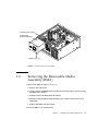
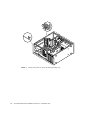
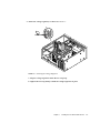
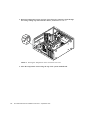
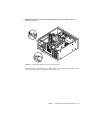
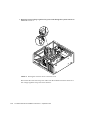
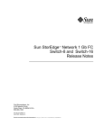
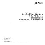
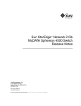
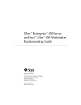
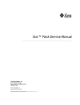
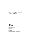
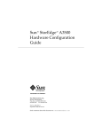
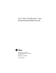
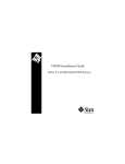
Sun™ Noise Reduction Kit
Installation Instructions
For Sun™ Ultra™ 30 and Sun Ultra 60 Workstations
Sun Microsystems, Inc.
901 San Antonio Road
Palo Alto, CA 94303-4900 USA
650 960-1300
Fax 650 969-9131
Part No. 806-2987-10
September 1999, Revision A
Send comments about this document to: [email protected]
Copyright 1999 Sun Microsystems, Inc., 901 San Antonio Road • Palo Alto, CA 94303-4900 USA. All rights reserved.
This product or document is protected by copyright and distributed under licenses restricting its use, copying, distribution, and decompilation.
No part of this product or document may be reproduced in any form by any means without prior written authorization of Sun and its licensors,
if any. Third-party software, including font technology, is copyrighted and licensed from Sun suppliers.
Parts of the product may be derived from Berkeley BSD systems, licensed from the University of California. UNIX is a registered trademark in
the U.S. and other countries, exclusively licensed through X/Open Company, Ltd. For Netscape Communicator™, the following notice applies:
Copyright 1995 Netscape Communications Corporation. All rights reserved.
Sun, Sun Microsystems, the Sun logo, AnswerBook2, docs.sun.com, and Solaris are trademarks, registered trademarks, or service marks of Sun
Microsystems, Inc. in the U.S. and other countries. All SPARC trademarks are used under license and are trademarks or registered trademarks
of SPARC International, Inc. in the U.S. and other countries. Products bearing SPARC trademarks are based upon an architecture developed by
Sun Microsystems, Inc.
The OPEN LOOK and Sun™ Graphical User Interface was developed by Sun Microsystems, Inc. for its users and licensees. Sun acknowledges
the pioneering efforts of Xerox in researching and developing the concept of visual or graphical user interfaces for the computer industry. Sun
holds a non-exclusive license from Xerox to the Xerox Graphical User Interface, which license also covers Sun’s licensees who implement OPEN
LOOK GUIs and otherwise comply with Sun’s written license agreements.
RESTRICTED RIGHTS: Use, duplication, or disclosure by the U.S. Government is subject to restrictions of FAR 52.227-14(g)(2)(6/87) and
FAR 52.227-19(6/87), or DFAR 252.227-7015(b)(6/95) and DFAR 227.7202-3(a).
DOCUMENTATION IS PROVIDED “AS IS” AND ALL EXPRESS OR IMPLIED CONDITIONS, REPRESENTATIONS AND WARRANTIES,
INCLUDING ANY IMPLIED WARRANTY OF MERCHANTABILITY, FITNESS FOR A PARTICULAR PURPOSE OR NONINFRINGEMENT, ARE DISCLAIMED, EXCEPT TO THE EXTENT THAT SUCH DISCLAIMERS ARE HELD TO BE LEGALLY INVALID.
Copyright 1999 Sun Microsystems, Inc., 901 San Antonio Road • Palo Alto, CA 94303-4900 Etats-Unis. Tous droits réservés.
Ce produit ou document est protégé par un copyright et distribué avec des licences qui en restreignent l’utilisation, la copie, la distribution, et la
décompilation. Aucune partie de ce produit ou document ne peut être reproduite sous aucune forme, par quelque moyen que ce soit, sans
l’autorisation préalable et écrite de Sun et de ses bailleurs de licence, s’il y en a. Le logiciel détenu par des tiers, et qui comprend la technologie
relative aux polices de caractères, est protégé par un copyright et licencié par des fournisseurs de Sun.
Des parties de ce produit pourront être dérivées des systèmes Berkeley BSD licenciés par l’Université de Californie. UNIX est une marque
déposée aux Etats-Unis et dans d’autres pays et licenciée exclusivement par X/Open Company, Ltd. La notice suivante est applicable à
Netscape Communicator™ : Copyright 1995 Netscape Communications Corporation. All rights reserved.
Sun, Sun Microsystems, the Sun logo, AnswerBook2, docs.sun.com, et Solaris sont des marques de fabrique ou des marques déposées, ou
marques de service, de Sun Microsystems, Inc. aux Etats-Unis et dans d’autres pays. Toutes les marques SPARC sont utilisées sous licence et
sont des marques de fabrique ou des marques déposées de SPARC International, Inc. aux Etats-Unis et dans d’autres pays. Les produits portant
les marques SPARC sont basés sur une architecture développée par Sun Microsystems, Inc.
L’interface d’utilisation graphique OPEN LOOK et Sun™ a été développée par Sun Microsystems, Inc. pour ses utilisateurs et licenciés. Sun
reconnaît les efforts de pionniers de Xerox pour la recherche et le développement du concept des interfaces d’utilisation visuelle ou graphique
pour l’industrie de l’informatique. Sun détient une licence non exclusive de Xerox sur l’interface d’utilisation graphique Xerox, cette licence
couvrant également les licenciés de Sun qui mettent en place l’interface d’utilisation graphique OPEN LOOK et qui en outre se conforment aux
licences écrites de Sun.
CETTE PUBLICATION EST FOURNIE "EN L’ETAT" ET AUCUNE GARANTIE, EXPRESSE OU IMPLICITE, N’EST ACCORDEE, Y COMPRIS
DES GARANTIES CONCERNANT LA VALEUR MARCHANDE, L’APTITUDE DE LA PUBLICATION A REPONDRE A UNE UTILISATION
PARTICULIERE, OU LE FAIT QU’ELLE NE SOIT PAS CONTREFAISANTE DE PRODUIT DE TIERS. CE DENI DE GARANTIE NE
S’APPLIQUERAIT PAS, DANS LA MESURE OU IL SERAIT TENU JURIDIQUEMENT NUL ET NON AVENU.
Please
Recycle
CHAPTER
1
Installing the Sun Noise Reduction
Kit
This chapter describes how to install the Sun noise reduction kit in a Sun Ultra 30 or
Sun Ultra 60 workstation. The installation procedure illustrates the procedure with
an Ultra 60 system, but installation is the same for both systems.
Installing the noise reduction kit involves the following steps.
Note – The procedures described here apply to both the Sun Ultra 30 and Ultra 60
workstations. Some steps,called out in the procedure description, are covered in
more detail in the two systems’ respective service manuals; Sun Ultra 30 Service
Manual, 802-7719, or Sun Ultra 60 Service Manual, 805-1709.
1. Removing the power supply from the system chassis.
2. Removing the Removable Media Assembly from the system chassis.
3. Installing the noise reduction kit inside the chassis
4. Routing the noise reduction kit wiring inside the chassis and making all required
connections.
5. Replacing the Removable Media Assembly into the system.
6. Replacing the power supply into the system.
1-1
1.1
Removing the Power Supply
1. Power off the system unit.
Refer to your system’s service manual.
2. Remove the side access cover.
Refer to your system’s service manual.
Caution – When removing the power supply, attach the copper end of the wrist
strap to the system unit chassis, not the power supply.
3. Disconnect the power cord from the power supply.
4. Attach the wrist strap.
Refer to your system’s service manual.
5. Remove the power supply as follows (FIGURE 1-1):
a. Using a number 2 Phillips-head screwdriver, loosen the four captive screws
securing the power supply to the chassis.
b. Slide the power supply from the chassis rear until the power supply is stopped
by the power supply cables.
c. Disconnect the peripheral cable connector from the power supply (not
illustrated).
d. Disconnect the power supply cables from the motherboard (not illustrated).
e. Remove the power supply from the chassis.
1-2
Sun Noise Reduction Kit Installation Instructions • September 1999
Peripheral power cable
Power supply
(partially extended)
Captive screw (4)
FIGURE 1-1
1.2
Removing the Power Supply
Removing the Removable Media
Assembly (RMA)
1. Remove the RMA as follows (FIGURE 1-2):
a. Remove the front bezel.
b. Using a number 2 Phillips-head screwdriver, loosen the captive screws securing
the RMA to the chassis.
c. Partially remove the RMA from the chassis.
d. Disconnect the peripheral cables and the power cables from the drives (not
illustrated).
e. Remove the RMA from the chassis.
2. Place the RMA on an antistatic mat.
Chapter 1
Installing the Sun Noise Reduction Kit
1-3
RMA
Diskette drive
CD-ROM drive
(or 4-mm or 8-mm tape drive)
Captive screw (2)
Front bezel
FIGURE 1-2
1-4
Removing the Removable Media Assembly
Sun Noise Reduction Kit Installation Instructions • September 1999
1.3
Installing the Noise Reduction Kit
The noise reduction kit consists of the following parts, as shown in FIGURE 1-3:
Fan power connector (2)
Temperature sensor
Pass-through power
connector
Wiring Routing Clip
Voltage regulator
FIGURE 1-3
Noise Reduction Kit Components
1. Insert the nylon tie wrap in the system internal chassis as shown in FIGURE 1-4.
a. Route the tie, tapered end pointing down, through two holes in the internal
chassis.
b. Slip the tapered end of the tie into the tie wrap lock.
2. Install the wiring routing clip inside the chassis, as shown in FIGURE 1-4.
a. Peel off the paper backing from the clip.
b. Press the adhesive back of the clip on to the top of the chassis as shown.
Chapter 1
Installing the Sun Noise Reduction Kit
1-5
FIGURE 1-4
1-6
Placing the Nylon Tie Wrap and Wiring Routing Clip
Sun Noise Reduction Kit Installation Instructions • September 1999
3. Attach the voltage regulator, as shown in FIGURE 1-5.
FIGURE 1-5
Attaching the Voltage Regulator
a. Slip the voltage regulator inside the tie wrap loop.
b. Tighten the tie wrap firmly to hold the voltage regulator in place.
Chapter 1
Installing the Sun Noise Reduction Kit
1-7
4. Route the temperature sensor and one of the fan power connector leads through
the wiring routing clip and inside the chassis, as shown in FIGURE 1-6.
FIGURE 1-6
Routing the Temperature Sensor and Fan Power Lead
5. Place the temperature sensor along the top of the system motherboard.
1-8
Sun Noise Reduction Kit Installation Instructions • September 1999
6. Route the fan power connector lead through the large holes in the chassis as
shown in FIGURE 1-7.
FIGURE 1-7
Routing the Rear Fan Power Connector Lead
Disconnect the rear CPU fan power cable from the system motherboard and connect
it to the voltage regulator fan power lead connector.
Chapter 1
Installing the Sun Noise Reduction Kit
1-9
7. Route the second voltage regulator fan power lead through the systems chassis as
shown in FIGURE 1-8.
FIGURE 1-8
Routing the Front Fan Power Connector Lead
Disconnect the front CPU fan power cable from the motherboard and connect it to
the voltage regulator fan power lead connector.
1-10
Sun Noise Reduction Kit Installation Instructions • September 1999
P3
P3
8. Connect the female connector of the voltage regulator power pass-through
connector to the SCSI device power connector labeled “P3” as shown in FIGURE 1-9.
FIGURE 1-9
Connecting the Pass-Through Power Connector
Note – You will connect the male connector of the voltage regulator power passthrough connector to the SCSI device in the RMA, if one is installed.
You have finished installing the noise reduction kit.
Chapter 1
Installing the Sun Noise Reduction Kit
1-11
1.4
Replacing the RMA
Caution – Use proper ESD grounding techniques when handling components. Wear
an antistatic wrist strap and use an ESD-protected mat. Store ESD-sensitive
components in antistatic bags before placing them on any surface.
RMA
Diskette drive
CD-ROM drive
(or 4-mm or 8-mm tape drive)
Captive screw (2)
Front bezel
FIGURE 1-10
Replacing the Removable Media Assembly
1. Replace the RMA as follows (FIGURE 1-10):
1-12
Sun Noise Reduction Kit Installation Instructions • September 1999
a. Position the RMA into the chassis, connect the rear cable connectors as
required.
b. Using a number 2 Phillips-head screwdriver, tighten the captive screws
securing the RMA to the chassis.
2. Replace the front bezel.
1.5
Replacing the Power Supply
Caution – Use proper ESD grounding techniques when handling components. Wear
an antistatic wrist strap and use an ESD-protected mat. Store ESD-sensitive
components in antistatic bags before placing them on any surface.
1. Replace the power supply as follows (FIGURE 1-11):
a. Feed the power supply cables through the chassis opening; support the power
supply cables while engaging the power supply into the chassis rails.
b. Position the power supply into the chassis.
c. Slide the power supply toward the chassis front.
d. Connect the power cables to the motherboard.
e. Connect the peripheral cable connector to the power supply.
f. Replace the peripheral power cable through the cable routing clips.
Chapter 1
Installing the Sun Noise Reduction Kit
1-13
Peripheral power cable
Power supply
(partially extended)
Captive screw (4)
FIGURE 1-11
Replacing the Power Supply
g. Slide the power supply toward the chassis front until the power supply rear
panel is flush with the chassis.
h. Using a number 2 Phillips-head screwdriver, tighten the captive screws
securing the power supply to the chassis.
Note – Tighten the captive screws in a clockwise order beginning with the upper
right captive screw.
2. Detach the wrist strap.
3. Connect the AC power cord.
4. Replace the side access cover.
Refer to your system’s service manual.
5. Power on the system unit.
Refer to your system’s service manual.
1-14
Sun Noise Reduction Kit Installation Instructions • September 1999