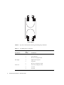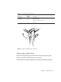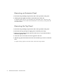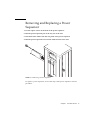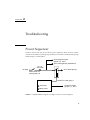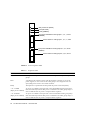
1
Sun™ Rack Service Manual
Sun Microsystems, Inc.
4150 Network Circle
Santa Clara, CA 95054 U.S.A.
650-960-1300
Part No. 816-6387-10
November 2002, Revision A
Send comments about this document to: [email protected]
Copyright 2002 Sun Microsystems, Inc., 4150 Network Circle, Santa Clara, California 95054, U.S.A. All rights reserved.
Sun Microsystems, Inc. has intellectual property rights relating to technology embodied in the product that is described in this document. In
particular, and without limitation, these intellectual property rights may include one or more of the U.S. patents listed at
http://www.sun.com/patents and one or more additional patents or pending patent applications in the U.S. and in other countries.
This document and the product to which it pertains are distributed under licenses restricting their use, copying, distribution, and
decompilation. No part of the product or of this document may be reproduced in any form by any means without prior written authorization of
Sun and its licensors, if any.
Third-party software, including font technology, is copyrighted and licensed from Sun suppliers.
Parts of the product may be derived from Berkeley BSD systems, licensed from the University of California. UNIX is a registered trademark in
the U.S. and in other countries, exclusively licensed through X/Open Company, Ltd.
Sun, Sun Microsystems, the Sun logo, AnswerBook2, docs.sun.com, and Solaris are trademarks or registered trademarks of Sun Microsystems,
Inc. in the U.S. and in other countries.
All SPARC trademarks are used under license and are trademarks or registered trademarks of SPARC International, Inc. in the U.S. and in other
countries. Products bearing SPARC trademarks are based upon an architecture developed by Sun Microsystems, Inc.
The OPEN LOOK and Sun™ Graphical User Interface was developed by Sun Microsystems, Inc. for its users and licensees. Sun acknowledges
the pioneering efforts of Xerox in researching and developing the concept of visual or graphical user interfaces for the computer industry. Sun
holds a non-exclusive license from Xerox to the Xerox Graphical User Interface, which license also covers Sun’s licensees who implement OPEN
LOOK GUIs and otherwise comply with Sun’s written license agreements.
Use, duplication, or disclosure by the U.S. Government is subject to restrictions set forth in the Sun Microsystems, Inc. license agreements and as
provided in DFARS 227.7202-1(a) and 227.7202-3(a) (1995), DFARS 252.227-7013(c)(1)(ii) (Oct. 1998), FAR 12.212(a) (1995), FAR 52.227-19, or
FAR 52.227-14 (ALT III), as applicable.
DOCUMENTATION IS PROVIDED "AS IS" AND ALL EXPRESS OR IMPLIED CONDITIONS, REPRESENTATIONS AND WARRANTIES,
INCLUDING ANY IMPLIED WARRANTY OF MERCHANTABILITY, FITNESS FOR A PARTICULAR PURPOSE OR NON-INFRINGEMENT,
ARE DISCLAIMED, EXCEPT TO THE EXTENT THAT SUCH DISCLAIMERS ARE HELD TO BE LEGALLY INVALID.
Copyright 2002 Sun Microsystems, Inc., 4150 Network Circle, Santa Clara, California 95054, Etats-Unis. Tous droits réservés.
Sun Microsystems, Inc. a les droits de propriété intellectuels relatants à la technologie incorporée dans le produit qui est décrit dans ce
document. En particulier, et sans la limitation, ces droits de propriété intellectuels peuvent inclure un ou plus des brevets américains énumérés
à http://www.sun.com/patents et un ou les brevets plus supplémentaires ou les applications de brevet en attente dans les Etats-Unis et dans
les autres pays.
Ce produit ou document est protégé par un copyright et distribué avec des licences qui en restreignent l’utilisation, la copie, la distribution, et la
décompilation. Aucune partie de ce produit ou document ne peut être reproduite sous aucune forme, parquelque moyen que ce soit, sans
l’autorisation préalable et écrite de Sun et de ses bailleurs de licence, s’il y ena.
Le logiciel détenu par des tiers, et qui comprend la technologie relative aux polices de caractères, est protégé par un copyright et licencié par des
fournisseurs de Sun.
Des parties de ce produit pourront être dérivées des systèmes Berkeley BSD licenciés par l’Université de Californie. UNIX est une marque
déposée aux Etats-Unis et dans d’autres pays et licenciée exclusivement par X/Open Company, Ltd.
Sun, Sun Microsystems, le logo Sun, AnswerBook2, docs.sun.com, et Solaris sont des marques de fabrique ou des marques déposées de Sun
Microsystems, Inc. aux Etats-Unis et dans d’autres pays.
Toutes les marques SPARC sont utilisées sous licence et sont des marques de fabrique ou des marques déposées de SPARC International, Inc.
aux Etats-Unis et dans d’autres pays. Les produits protant les marques SPARC sont basés sur une architecture développée par Sun
Microsystems, Inc.
L’interface d’utilisation graphique OPEN LOOK et Sun™ a été développée par Sun Microsystems, Inc. pour ses utilisateurs et licenciés. Sun
reconnaît les efforts de pionniers de Xerox pour la recherche et le développment du concept des interfaces d’utilisation visuelle ou graphique
pour l’industrie de l’informatique. Sun détient une license non exclusive do Xerox sur l’interface d’utilisation graphique Xerox, cette licence
couvrant également les licenciées de Sun qui mettent en place l’interface d ’utilisation graphique OPEN LOOK et qui en outre se conforment
aux licences écrites de Sun.
LA DOCUMENTATION EST FOURNIE "EN L’ÉTAT" ET TOUTES AUTRES CONDITIONS, DECLARATIONS ET GARANTIES EXPRESSES
OU TACITES SONT FORMELLEMENT EXCLUES, DANS LA MESURE AUTORISEE PAR LA LOI APPLICABLE, Y COMPRIS NOTAMMENT
TOUTE GARANTIE IMPLICITE RELATIVE A LA QUALITE MARCHANDE, A L’APTITUDE A UNE UTILISATION PARTICULIERE OU A
L’ABSENCE DE CONTREFAÇON.
Please
Recycle
Contents
1.
Sun Rack Service
1
Preparing the Rack for Service
1
Removing the Grounding Straps
Removing a Side Panel
3
Removing an Extension Panel
Removing the Top Panel
1
4
4
Removing and Replacing a Power Sequencer
Removing and Replacing a Power Strip
6
Removing and Replacing a Cable Assembly
2.
Removing a Cable Assembly
7
Replacing a Cable Assembly
8
Troubleshooting
13
Power Sequencer
13
Power Strips
5
7
16
iii
iv
Sun Rack Service Manual • November 2002
Preface
This document describes how to remove and replace the field replaceable parts in a
Sun Rack and contains some troubleshooting information for isolating faults.
Accessing Sun Documentation
You can view, print, or purchase a broad selection of Sun documentation, including
localized versions, at:
http://www.sun.com/documentation
Sun Welcomes Your Comments
Sun is interested in improving its documentation and welcomes your comments and
suggestions. You can email your comments to Sun at:
[email protected]
Please include the part number (816-6387-10) of your document in the subject line of
your email.
v
vi Sun Rack Service Manual • November 2002
CHAPTER
1
Sun Rack Service
All service procedures must be performed by qualified service personnel.
Read the Sun Rack Safety and Compliance document before attempting any service
procedures.
There are four types of field-replaceable units in the Sun™ Rack:
■
Power sequencers
■
Power strips
■
Cable harnesses
■
Top panel
Preparing the Rack for Service
Some maintenance tasks require that the panels be removed from the Sun Rack.
Removing the Grounding Straps
There are three grounding straps mounted to each corner of the top of the rack
frame. FIGURE 1-1 and TABLE 1-1 identify which straps are connected to which panels.
Before removing any panel, the grounding strap must be disconnected from the
panel.
1
1
2
3
4
5
6
7
8
9
10
11
12
Front of Rack
FIGURE 1-1
Top View of Rack Frame Showing Grounding Strap Terminals
TABLE 1-1
Grounding Strap Connections
Rack Terminal
Grounding
Strap
Number
Connected to:
Rear Left
1
Left extension panel
2
Left side panel
3
Rear door if hinged on left
4
Right extension panel
5
Top panel
6
Rear door if hinged on right
7
Front door if hinged on left
8
not used
9
not used
Rear Right
Front Left
2
Sun Rack Service Manual • November 2002
TABLE 1-1
Grounding Strap Connections
Rack Terminal
Grounding
Strap
Number
Connected to:
Front Right
10
Right side panel
11
Front door if hinged on right
12
not used
FIGURE 1-2
Typical Grounding Strap Connection
Removing a Side Panel
1. Disconnect the grounding strap from the stud on the top inside of the panel.
2. Release two latches on the bottom inside of the panel.
3. Pull the bottom of the panel slightly away from the rack and lift up the panel.
Chapter 1
Sun Rack Service
3
Removing an Extension Panel
1. Disconnect the grounding strap from the stud on the top inside of the panel.
2. Lift the panel up slightly and slide it toward the front of the rack.
To hold the panel in place, a tab attached to the panel slides into a bracket on the
rack side. There are two of these tabs and brackets, one at the top of the panel and
one at the bottom.
Removing the Top Panel
1. Disconnect the grounding strap from the stud on the top inside of the panel.
2. Disconnect the top panel power supply power cord from power strip.
3. Remove the logo panel from the top front of the rack, or if your Sun Rack has a
front door, open the door.
4. Loosen the four screws that secure the top panel to the rack.
5. Slide the top panel toward the front of the rack and lift it up to remove it from the
rack.
To replace the top panel, reverse the order of the removal procedure.
4
Sun Rack Service Manual • November 2002
Removing and Replacing a Power
Sequencer
1. Loosen captive screws on the front of the power sequencer.
2. Pull the power sequencer part of the way out of the rack.
3. Disconnect three cables from the rear panel of the power sequencer.
4. Pull the power sequencer free from the cables and out of the rack.
FIGURE 1-3
Removing a Power Sequencer
To replace a power sequencer, reverse the steps of the power sequencer removal
procedure.
Chapter 1
Sun Rack Service
5
Removing and Replacing a Power Strip
In order to remove the inner power strip, you must first remove the outer power
strip (the one closer to the back of the rack). The removal procedure for both power
strips is the same.
1. Disconnect the cable from the bottom of the power strip.
2. Loosen the retaining screw at the top of the power strip and pull the top of the
power strip toward the back of the rack.
3. Pull the power strip up and out so that the tab at the bottom of the power strip
clears the bracket.
FIGURE 1-4
Power Strip
To replace a power strip, reverse the steps of the power strip removal procedure.
To replace the inner power strip, the outer power strip must be removed.
6
Sun Rack Service Manual • November 2002
Removing and Replacing a Cable
Assembly
Removing a Cable Assembly
1. Disconnect the cable harness to be removed from its power strip.
2. On the power sequencer side of the rack, remove the side panel, the power strip
bracket cover, the power strip bracket, and both power strips.
FIGURE 1-5
Cable Harness
3. Disconnect the cable harness from the power input panel.
a. Remove two screws holding the power input panel to the rack.
b. Remove one screw that holds the connector cluster to the power input panel
assembly.
4. Disconnect the cable harness from the power sequencer.
a. Loosen two screws on the front panel of the power sequencer.
Chapter 1
Sun Rack Service
7
b. Pull the power sequencer out the front of the rack.
c. Disconnect the cable harness from the three connectors on the power
sequencer. Set the power sequencer aside.
5. Loosen the screw that holds the cable harness carrier plate to the rack.
6. Lift up the rear of the carrier plate so the notch clears the edge on which it is
seated.
7. Pull the carrier plate and cable harness out the back of the rack.
Replacing a Cable Assembly
Each cable harness consists of three cables bundled together on a carrier plate.
Viewed from the back of the rack, the cable harnesses and power sequencers are
mounted on the left side of the rack. The lower cable harness (B) is shorter than the
upper harness (A). Each cable carrier plate is installed in the slot above its respective
sequencer. It is more convenient to install the cables for the lower sequencer (B) first.
1. Remove the rack side panel, the power strip bracket cover, and the power strip
bracket.
8
Sun Rack Service Manual • November 2002
2. Holding the carrier plate, pass the cable bundle through the space between the
outer frame and the rack mounting rail.
FIGURE 1-6
Cable Harness and Carrier Plate
After the cable ends are inserted, insert the carrier plate and push it forward toward
the front of the rack. As you slide the carrier plate in, the front end is guided by a
vertical channel on the front cover plate.
As the carrier is close to being fully inserted, a small tab on its bottom edge aligns
with a slot in the channel to position the carrier to the right. As this tab fully engages
a small vertical slot in the carrier plate engages and allows the carrier to drop into its
final position. At this point tighten the captive screw.
3. Repeat Step 2 for the upper cable harness (A).
Chapter 1
Sun Rack Service
9
4. Attach the two connector clusters to the power input panel.
FIGURE 1-7
Attaching Connector Clusters to the Power Input Panel
Mount the lower cable harness cluster (B) on the right side of the input panel.
Position each cluster under the power input panel with the open side up. The cables
are positioned on the left side of the power input panel. The connectors engage with
the slots in the front surface. Secure each cluster with a single screw between the two
connectors.
While attaching the left-hand cluster (A) to the power input panel, ensure that the
cluster supports the two cables from the right-hand cluster (B).
10
Sun Rack Service Manual • November 2002
5. Attach the input power panel to the rack with two 8 mm screws, split washers,
and flat washers.
FIGURE 1-8
Attaching the Power Input Panel to the Rack
6. Reinstall the power strip mounting bracket and the power strip mounting bracket
cover.
Chapter 1
Sun Rack Service
11
12
Sun Rack Service Manual • November 2002
CHAPTER
2
Troubleshooting
Power Sequencer
FIGURE 2-1 shows only one AC circuit in a power sequencer. There are four of these
circuits for the odd (1-7) outlet groups and five more for the even (0-8) outlet groups.
Outlet Group 9 is unswitched.
AC to relays for outlet
groups 3, 5, and 7
AC to outlet group 9 (unswitched)
~ AC 1-9
ODD (LED)
AC Input
AC to outlet group 1
Power switch for
outlet groups 1-9
Control
Fault (LED)
Control for outlet group 1
Control for outlet
groups 3, 5, and 7
Ready (LED)
FIGURE 2-1
Simplified Block Diagram of a Single Circuit in a Power Sequencer
13
Okay to Remove (BLUE)
Fault (YELLOW)
Ready (GREEN)
Input power available for outlet groups 1, 3, 5, 7, and 9
(GREEN)
Power switch for outlet groups 1, 3, 5, 7, and 9
Input power available for outlet groups 0, 2, 4, 6, and 8
(GREEN)
Power switch for outlet groups 0, 2, 4, 6, and 8
FIGURE 2-2
Power Sequencer LEDs
TABLE 2-1
Sequencer LEDs
LED
ON indicates
Okay to Remove
The sequencer output AC is turned off; there is no power to the power strip outlet
groups.
Fault
A problem in the sequencer; either with the sequencer controller or one of the
power supplies, or one or more of the outlet groups is not energized. Note: An
open (OFF) power switch is not a Fault condition.
Ready
The sequencer is operational and has passed the power-on-self-test (POST).
~ AC 1-9 ODD
(Input power available)
AC power is available to the input side of the odd-numbered outlet group relays.
Note: this LED only indicates that power is available to the outlet group relays; it
does not indicate that AC power is output from the sequencer.
~ AC 0-8 EVEN
(Input power available)
AC power is available to the input side of the even-numbered outlet group relays.
Note: this LED only indicates that power is available to the outlet group relays; it
does not indicate that AC power is output from the sequencer.
14
Sun Rack Service Manual • November 2002
TABLE 2-2
LED Indicators on the Power Sequencer
Condition
LED
LED Status
Troubleshooting Action
Normal operation
Okay to Remove
OFF
No action required.
Fault
OFF
Ready
ON
~ AC 1-9 ODD
ON
~ AC 0-8 EVEN
ON
Okay to Remove
OFF
Fault
ON
Ready
(ON or OFF)
~ AC 1-9 ODD
ON
~ AC 0-8 EVEN
ON
Okay to Remove
ON
Fault
(ON or OFF)
Ready
(ON or OFF)
~ AC 1-9 ODD
OFF
~ AC 0-8 EVEN
OFF
Okay to Remove
OFF
Fault
OFF
Ready
ON
~ AC 1-9 ODD
OFF
~ AC 0-8 EVEN
ON
Sequencer fault
Turned off
Missing AC input
1. Turn off both power switches. The blue
“Okay to Remove” LED lights.
2. Remove and replace the power sequencer.
You can safely remove the sequencer.
Assuming both power switches are on, start
troubleshooting the input to the sequencer:
1. Input power panel connectors
2. Branch (wall) circuit breaker
Chapter 2
Troubleshooting
15
Power Strips
Each power strip is divided into outlet groups. Each outlet group has four outlets
(sockets). The outlet groups are divided into two sets: odd and even. The odd outlet
groups are 1, 3, 5, 7, and 9. The even outlet groups are 0, 2, 4, 6, and 8. The odd
outlet groups receive their power from one AC input and the even outlet groups
receive their power from the other AC input.
The power strips have a power indicator LED for each outlet group.
A single LED on a
power strip is not lit.
Power sequencer
Fault light on?
Yes
Replace power
sequencer.
No
Voltage okay at the
outlet group?
Yes
LED is faulty. Replace
power strip.
FIGURE 2-3
16
Troubleshooting a Power Strip
Sun Rack Service Manual • November 2002
No
Replace cable
harness.