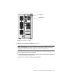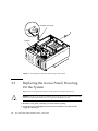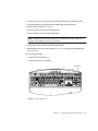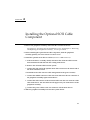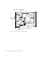
1
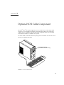
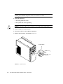
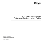
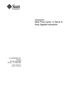
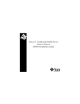
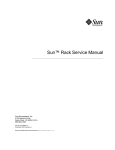
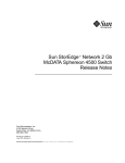
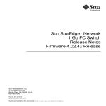
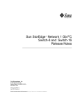
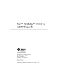
Sun™ Ultra™ 80 SCSI Cable Installation Guide Sun Microsystems, Inc. 901 San Antonio Road Palo Alto, CA 94303 U.S.A. 650-960-1300 Part No. 806-4423-10 March 2000, Revision A Send comments about this document to: [email protected] Copyright 2000 Sun Microsystems, Inc., 901 San Antonio Road • Palo Alto, CA 94303-4900 USA. All rights reserved. This product or document is protected by copyright and distributed under licenses restricting its use, copying, distribution, and decompilation. No part of this product or document may be reproduced in any form by any means without prior written authorization of Sun and its licensors, if any. Third-party software, including font technology, is copyrighted and licensed from Sun suppliers. Parts of the product may be derived from Berkeley BSD systems, licensed from the University of California. UNIX is a registered trademark in the U.S. and other countries, exclusively licensed through X/Open Company, Ltd. For Netscape Communicator™, the following notice applies: Copyright 1995 Netscape Communications Corporation. All rights reserved. Sun, Sun Microsystems, the Sun logo, AnswerBook2, docs.sun.com, Ultra, and Solaris are trademarks, registered trademarks, or service marks of Sun Microsystems, Inc. in the U.S. and other countries. All SPARC trademarks are used under license and are trademarks or registered trademarks of SPARC International, Inc. in the U.S. and other countries. Products bearing SPARC trademarks are based upon an architecture developed by Sun Microsystems, Inc. The OPEN LOOK and Sun™ Graphical User Interface was developed by Sun Microsystems, Inc. for its users and licensees. Sun acknowledges the pioneering efforts of Xerox in researching and developing the concept of visual or graphical user interfaces for the computer industry. Sun holds a non-exclusive license from Xerox to the Xerox Graphical User Interface, which license also covers Sun’s licensees who implement OPEN LOOK GUIs and otherwise comply with Sun’s written license agreements. RESTRICTED RIGHTS: Use, duplication, or disclosure by the U.S. Government is subject to restrictions of FAR 52.227-14(g)(2)(6/87) and FAR 52.227-19(6/87), or DFAR 252.227-7015(b)(6/95) and DFAR 227.7202-3(a). DOCUMENTATION IS PROVIDED “AS IS” AND ALL EXPRESS OR IMPLIED CONDITIONS, REPRESENTATIONS AND WARRANTIES, INCLUDING ANY IMPLIED WARRANTY OF MERCHANTABILITY, FITNESS FOR A PARTICULAR PURPOSE OR NONINFRINGEMENT, ARE DISCLAIMED, EXCEPT TO THE EXTENT THAT SUCH DISCLAIMERS ARE HELD TO BE LEGALLY INVALID. Copyright 2000 Sun Microsystems, Inc., 901 San Antonio Road • Palo Alto, CA 94303-4900 Etats-Unis. Tous droits réservés. Ce produit ou document est protégé par un copyright et distribué avec des licences qui en restreignent l’utilisation, la copie, la distribution, et la décompilation. Aucune partie de ce produit ou document ne peut être reproduite sous aucune forme, par quelque moyen que ce soit, sans l’autorisation préalable et écrite de Sun et de ses bailleurs de licence, s’il y en a. Le logiciel détenu par des tiers, et qui comprend la technologie relative aux polices de caractères, est protégé par un copyright et licencié par des fournisseurs de Sun. Des parties de ce produit pourront être dérivées des systèmes Berkeley BSD licenciés par l’Université de Californie. UNIX est une marque déposée aux Etats-Unis et dans d’autres pays et licenciée exclusivement par X/Open Company, Ltd. La notice suivante est applicable à Netscape Communicator™: Copyright 1995 Netscape Communications Corporation. Tous droits réservés. Sun, Sun Microsystems, the Sun logo, AnswerBook2, docs.sun.com, Ultra, et Solaris sont des marques de fabrique ou des marques déposées, ou marques de service, de Sun Microsystems, Inc. aux Etats-Unis et dans d’autres pays. Toutes les marques SPARC sont utilisées sous licence et sont des marques de fabrique ou des marques déposées de SPARC International, Inc. aux Etats-Unis et dans d’autres pays. Les produits portant les marques SPARC sont basés sur une architecture développée par Sun Microsystems, Inc. L’interface d’utilisation graphique OPEN LOOK et Sun™ a été développée par Sun Microsystems, Inc. pour ses utilisateurs et licenciés. Sun reconnaît les efforts de pionniers de Xerox pour la recherche et le développement du concept des interfaces d’utilisation visuelle ou graphique pour l’industrie de l’informatique. Sun détient une licence non exclusive de Xerox sur l’interface d’utilisation graphique Xerox, cette licence couvrant également les licenciés de Sun qui mettent en place l’interface d’utilisation graphique OPEN LOOK et qui en outre se conforment aux licences écrites de Sun. CETTE PUBLICATION EST FOURNIE "EN L’ETAT" ET AUCUNE GARANTIE, EXPRESSE OU IMPLICITE, N’EST ACCORDEE, Y COMPRIS DES GARANTIES CONCERNANT LA VALEUR MARCHANDE, L’APTITUDE DE LA PUBLICATION A REPONDRE A UNE UTILISATION PARTICULIERE, OU LE FAIT QU’ELLE NE SOIT PAS CONTREFAISANTE DE PRODUIT DE TIERS. CE DENI DE GARANTIE NE S’APPLIQUERAIT PAS, DANS LA MESURE OU IL SERAIT TENU JURIDIQUEMENT NUL ET NON AVENU. Please Recycle Preface The Sun Utra 80 SCSI Cable Installation Guide describes how to install the Sun Ultra 80 SCSI cable optional component. Related Documentation Application Title Part Number Service Sun Ultra 80 Service Manual 805-6618 Accessing Sun Documentation Online The docs.sun.comsm web site enables you to access Sun technical documentation on the Web. You can browse the docs.sun.com archive or search for a specific book title or subject at: http://docs.sun.com iii Ordering Sun Documentation Fatbrain.com, an Internet professional bookstore, stocks select product documentation from Sun Microsystems, Inc. For a list of documents and how to order them, visit the Sun Documentation Center on Fatbrain.com at: http://www1.fatbrain.com/documentation/sun Sun Welcomes Your Comments Sun is interested in improving its documentation and welcomes your comments and suggestions. You can email your comments to Sun at: [email protected] Please include the part number of your document in the subject line of your email. iv Sun Ultra 80 SCSI Cable Installation Guide • March 2000 Contents Preface 1. 2. 3. 4. iii Optional SCSI Cable Component 1-1 1.1 Optional SCSI Cable Component Kit 1.2 System Hardware Requirements 1.3 SCD Compliance 1.4 How to Proceed 1-2 1-2 1-2 1-3 Powering On/Off and Internal Access 2-1 2.1 Powering Off the System/Removing the Access Panel 2.2 Attaching the Antistatic Wrist Strap 2.3 Replacing the Access Panel/Powering On the System 2-5 Removing and Replacing the Peripheral Assembly 3.1 Removing the Peripheral Assembly 3.2 Installing an Optional Component 3.3 Replacing the Peripheral Assembly 2-1 2-6 3-1 3-1 3-3 3-4 Installing the Optional SCSI Cable Component 4-1 Contents v vi Sun Ultra 80 SCSI Cable Installation Guide • March 2000 CHAPTER 1 Optional SCSI Cable Component The Sun Ultra 80 system supports up to two SCSI devices, with 50-pin SCSI connectors, in its peripheral assembly (removable media drive bay). This book explains how to install the optional SCSI cable component when a second SCSI removable media drive is added to the system. For more detail on the Sun Ultra 80 system, please consult the Sun Ultra 80 Service Manual, part number 805-6618. Peripheral assembly (removable media drive bay) FIGURE 1-1 Ultra 80 Workstation 1-1 1.1 Optional SCSI Cable Component Kit Each optional SCSI cable component kit contains: ■ ■ ■ 1.2 This book SCSI cable Antistatic wrist strap System Hardware Requirements System hardware requirements include a second SCSI device with a 50-pin connector, to be installed in the peripheral assembly (removable media drive bay). The device may be a 4-mm tape drive, an 8-mm tape drive, or a second CD-ROM drive. 1.3 SCD Compliance Sun Ultra 80 systems have been independently tested and verified to comply with revision 2.1 of the SPARC™ Compliance Definition (SCD) developed by SPARC International, Inc. These systems are binary compatible with all other systems and software that conform to SCD version 2.1. 1-2 Sun Ultra 80 SCSI Cable Installation Guide • March 2000 1.4 How to Proceed If you are an experienced technician, system administrator, authorized service provider (ASP), or advanced computer system end user who has experience troubleshooting and replacing hardware, you may want to start with Chapter 4 “Installing the Optional SCSI Cable Component.” Otherwise, first read and perform the procedures in sequence in Chapter 2 “Powering On/Off and Internal Access”, and Chapter 3 “Removing and Replacing the Peripheral Assembly.” Chapter 1 Optional SCSI Cable Component 1-3 1-4 Sun Ultra 80 SCSI Cable Installation Guide • March 2000 CHAPTER 2 Powering On/Off and Internal Access This chapter contains procedures to power on and off the system, and instructions on how to access the system for service: ■ ■ ■ 2.1 Section 2.1 “Powering Off the System/Removing the Access Panel” on page 2-1 Section 2.2 “Attaching the Antistatic Wrist Strap” on page 2-5 Section 2.3 “Replacing the Access Panel/Powering On the System” on page 2-6 Powering Off the System/Removing the Access Panel To power off the system and remove the access panel: Caution – Prior to turning off the system power, exit from the operating system. Failure to do so may result in data loss. 1. Back up system files and data. 2. Halt the system. Caution – Pressing the power switch does not remove all power from the system; a trickle voltage remains in the power supply. To remove all power from the system, disconnect the power cord. 3. Momentarily press the front panel power switch (FIGURE 2-1) and follow the instructions on the screen. 2-1 Note – If the system will not shut down, such as when the operating system has crashed, press and hold the power switch for at least five seconds. 4. Verify the following: a. The front panel LED is off. b. The system fans are not spinning. Caution – Disconnect the power cord prior to servicing system components. 5. Turn off the power to the monitor. 6. Disconnect cables to any peripheral equipment. 7. Remove the lock block, if installed (FIGURE 2-2). Power switch FIGURE 2-1 2-2 System Power Sun Ultra 80 SCSI Cable Installation Guide • March 2000 Lock block Workstation FIGURE 2-2 Lock Block Location 8. Remove the access panel as follows (FIGURE 2-3): Note – Removing the access panel activates the system power interlock circuit. This safety mechanism prevents all DC voltages (except 5 VDC standby power) from reaching any internal components when the access panel is removed. a. Lay the system in the service position. b. Press down on the two depressions at the top of the access panel. Tilt the top of the access panel out about an inch. c. Lift the access panel up and clear of the chassis. Chapter 2 Powering On/Off and Internal Access 2-3 Access panel Depression (2) FIGURE 2-3 2-4 Removing/Replacing the Access Panel Sun Ultra 80 SCSI Cable Installation Guide • March 2000 2.2 Attaching the Antistatic Wrist Strap Caution – Wear an antistatic wrist strap and use an ESD-protected mat when handling components. When servicing or removing system components, attach an ESD strap to your wrist, then to a metal area on the chassis, and then disconnect the power cord from the system and the wall receptacle. Following this caution equalizes all electrical potentials with the system. 1. Disconnect the power cord. 2. Attach the antistatic wrist strap as follows (FIGURE 2-4): a. Unwrap the first two folds of the antistatic wrist strap and wrap the adhesive side firmly against your wrist. b. Peel the liner from the copper foil at the opposite end of the antistatic wrist strap. c. Attach the copper end of the antistatic wrist strap to the chassis. Chapter 2 Powering On/Off and Internal Access 2-5 Antistatic wrist strap Chassis FIGURE 2-4 2.3 Attaching the Antistatic Wrist Strap to the Chassis Replacing the Access Panel/Powering On the System Replace the access panel and power on the system as follows (FIGURE 2-3): Caution – If the access panel is installed incorrectly, the power interlock circuit will remain activated. Ensure that the access panel is installed correctly. 1. Hold the access panel, centering it over the chassis opening. 2. Lower the access panel lightly onto the chassis until the access panel hooks engage the chassis rail. 2-6 Sun Ultra 80 SCSI Cable Installation Guide • March 2000 3. Tilt the top of the access panel in toward the chassis until it clicks into place. 4. Verify that the access panel clicks into both sides of the chassis top. 5. Replace the lock block (FIGURE 2-2). 6. Place the system into the operating position. 7. Turn on power to all connected peripherals. Note – Peripheral power is activated prior to system power so the system can recognize the peripherals when it is activated. 8. Connect the power cord to the wall and the system. 9. Momentarily press the power switch (FIGURE 2-1) or the Type-6 keyboard power key (FIGURE 2-5). 10. Verify the following: a. The front panel LED is on. b. The system fans are spinning. Power key Num Lock Help Esc F1 F2 F3 F4 F5 F6 Caps Lock F7 Scroll Lock F8 Compose F9 F10 F11 F12 Print Screen Scroll Lock SysRq Stop Again ~ ! ` 1 Props Undo Tab Front Copy @ # 2 $ 3 Q % 4 W ^ 5 E & 6 R * 7 T ( 8 Y ) 9 U _ 0 I + P { S D F G H J K L : ; Open Paste Find Cut FIGURE 2-5 Z X C V Shift Control B N M < , > . | } [ A Caps Lock Break Insert Home Page Up Num Lock / * - Del End Page Down 7 8 9 + = - O Back Space ] \ " Enter Pause PgUp Home 4 5 6 1 2 3 ' ? Shift / Alt End Compose Alt Graph Enter PgDn 0 . Ins Del Type-6 Keyboard Chapter 2 Powering On/Off and Internal Access 2-7 2-8 Sun Ultra 80 SCSI Cable Installation Guide • March 2000 CHAPTER 3 Removing and Replacing the Peripheral Assembly To remove and replace a peripheral assembly drive, it is necessary to remove and replace the peripheral assembly. Note – A peripheral assembly drive can be a CD-ROM drive, a 4-mm tape drive, an 8-mm tape drive, or any offered optional drive component, such as a PCI-connected device. 3.1 Removing the Peripheral Assembly 1. Remove any CD-ROM, tape, or diskette in the drive. 2. Power off the system and remove the access panel. See Section 2.1 “Powering Off the System/Removing the Access Panel” on page 2-1. Caution – Use proper ESD grounding techniques when handling components. Wear an antistatic wrist strap and use an ESD-protected mat. Store ESD-sensitive components in antistatic bags before placing them on any surface. 3. Attach the antistatic wrist strap. See Section 2.2 “Attaching the Antistatic Wrist Strap” on page 2-5. 4. Remove the peripheral assembly as follows (FIGURE 3-1 and FIGURE 3-2): a. Remove the peripheral bezel assembly by pressing down on the top of the bezel and pulling it straight out from the chassis. 3-1 b. Using a No. 2 Phillips screwdriver, remove the four screws securing the peripheral assembly to the chassis. c. Partially remove the peripheral assembly from the chassis. d. Disconnect the power and interface cables from all drives installed in the peripheral assembly. e. Remove the peripheral assembly from the chassis. 5. Place the peripheral assembly on an antistatic mat. Peripheral assembly Screw (4) Peripheral bezel assembly FIGURE 3-1 3-2 Removing and Replacing the Peripheral Assembly Sun Ultra 80 SCSI Cable Installation Guide • March 2000 3.2 Installing an Optional Component Note – Ensure that the peripheral power cable and all data cables are properly routed through the clips adjacent to the peripheral assembly. Route the SCSI data cable through the cable management hooks (part of chassis) adjacent to the hard drive cage. Caution – Use proper ESD grounding techniques when handling components. Wear an antistatic wrist strap and use an ESD-protected mat. Store ESD-sensitive components in antistatic bags before placing them on any surface. 1. Remove the filler panel, if necessary (FIGURE 3-2). 2. Position the optional component into the middle shelf of the peripheral assembly. 3. Using a No. 2 Phillips screwdriver, tighten the four screws securing the optional component to the peripheral assembly. 4. Replace the peripheral assembly. See Section 3.3 “Replacing the Peripheral Assembly” on page 3-4. Chapter 3 Removing and Replacing the Peripheral Assembly 3-3 Filler panel Screw (4) Screw (4) CD-ROM drive Optional component location Filler panel Diskette drive FIGURE 3-2 3.3 Installing Any Optional Tape Drive Component Replacing the Peripheral Assembly Caution – Use proper ESD grounding techniques when handling components. Wear an antistatic wrist strap and use an ESD-protected mat. Store ESD-sensitive components in antistatic bags before placing them on any surface. 1. Replace the peripheral assembly as follows (FIGURE 3-2): a. Position the peripheral assembly into the chassis. b. Connect the rear cable connectors as required. c. If an optional drive component is being installed, undress the optional drive component power harness and route it from the CPU area into the peripheral area. d. Using a No. 2 Phillips screwdriver, tighten the captive screws securing the peripheral assembly to the chassis. 2. Replace the peripheral bezel assembly. 3-4 Sun Ultra 80 SCSI Cable Installation Guide • March 2000 3. Detach the antistatic wrist strap. 4. Replace the access panel and power-on the system. See Section 2.3 “Replacing the Access Panel/Powering On the System” on page 2-6. Chapter 3 Removing and Replacing the Peripheral Assembly 3-5 3-6 Sun Ultra 80 SCSI Cable Installation Guide • March 2000 CHAPTER 4 Installing the Optional SCSI Cable Component 1. Remove the peripheral assembly and install the second SCSI device. See Chapter 2 “Powering On/Off and Internal Access and Chapter 3 “Removing and Replacing the Peripheral Assembly”, for safe procedures. 2. Before installing the optional SCSI cable component, slide the peripheral assembly partially out of the chassis for easier access. 3. Install the optional SCSI cable as follows (FIGURE 4-1 and FIGURE 4-2): a. If the SCSI device is already cabled, disconnect the old SCSI cable from the SCSI terminator board and from the existing SCSI device. b. Remove the old SCSI cable from the system. c. Connect the male end of the optional SCSI cable connector to the female end of the SCSI terminator board. d. Install the SCSI cable onto the cable management hooks (part of chassis). e. Connect the middle connector of the new SCSI cable onto the rear connector of the peripheral assembly topmost SCSI device. f. Connect the end connector of the new SCSI cable onto the rear connector of the other SCSI device. The Sun Ultra 80 will support only two SCSI devices in the peripheral assembly. g. Connect the power cables to the rear connector of both SCSI devices. 4. Slide the peripheral assembly back into the system chassis. 4-1 SCSI terminator board Optional SCSI cable component SCSI cable middle connector SCSI cable end connector FIGURE 4-1 4-2 Installing the Optional SCSI Cable Component Sun Ultra 80 SCSI Cable Installation Guide • March 2000 Power connector (2) FIGURE 4-2 Reinstalling the Power Cables Chapter 4 Installing the Optional SCSI Cable Component 4-3 4-4 Sun Ultra 80 SCSI Cable Installation Guide • March 2000