1
WARRANTY
WARRANTY: Except with respect to those components parts and uses
which are hereinafter described, Ney Dental Inc. (NDI) warrants this
furnace to be free from defects in material and workmanship for a period
of two years from the date of sale. NDI’s liability under this warranty is
limited solely to repairing or, at NDI’s option, replacing those products
included within the warranty which are returned to NDI within the applicable warranty period (with shipping charges prepaid), and which are
determined by NDI to be defective. This warranty shall not apply to any
product which has been subject to misuse; negligence; or accident; or
misapplied; or modified; or repaired by unauthorized persons; or improperly installed.
Q200
Vacuum Porcelain Furnace
INSPECTION: Buyer shall inspect the product upon receipt. The buyer
shall notify NDI in writing of any claims of defects in material and workmanship within thirty days after the buyer discovers or should have
discovered the facts upon which such a claim is based. Failure of the
buyer to give written notice of such a claim within this time period shall
be deemed to be a waiver of such claim.
DISCLAIMER: The provisions here-in stated NDI sole obligation and
exclude all other remedies or warranties, expressed or implied, including
those related to MERCHANTABILITY and FITNESS FOR A PARTICULAR PURPOSE.
LIMITATION OF LIABILITY: Under no circumstances shall NDI be liable
to the buyer for any incidental, consequential or special damages, losses
or expenses.
LIMITATION OF ACTIONS: The buyer must initiate any action with
respect to claims under the warranty described in the first paragraph
within one year after the cause of action has accrued.
Corporate and Sales Office:
Ney Dental Inc.
65 West Dudley Town Road
Bloomfield, CT 06002-1316 USA
860.242.6188
FAX 860.769.5050
Product Service Office:
Ney Dental Inc.
Equipment Division
13553 Calimesa Blvd.
Yucaipa, CA 92399-2303 USA
909.795.2461
FAX 909.795.5268
Q200 9902 93-63-093
Operating Manual & Log
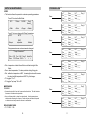
Model No:
94-94-000
94-94-003
94-94-004
Voltage:
100V 50/60Hz
120V 50/60Hz
230V 50/60Hz
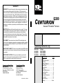
DESCRIPTION
PAGE
Safety ........................................ 2
Furnace Description ................... 3
Installation .................................. 4
Getting Started ................... 5
Program Log ............................ 11
Specifications .......................... 15
Features .................................. 16
Setup & Maintenance ............... 18
Other Operations ...................... 19
Error Codes .............................. 23
Parameter Description .............. 24
Accessories ............................. 26
Product Service ........................ 27
Warranty .............................. Back
SAFETY:
!
• If equipment is used in a manner not specified by the manufacturer, the
protection provided by the equipment may be impaired.
• Never operate furnace in close proximity to combustible materials or place
materials on top of the furnace.
• The furnace must be electrically grounded to a three wire electrical outlet
or receptacle. The electrical service provided must be a dedicated line of
the proper size according to local electrical codes.
• Disconnect the line cord before attempting to service the furnace.
• Do not attempt to service the furnace until you read and understand the
service manual. (See Manual under Accessories on page 23)
• Do not touch the reflective viewport window with fingers; the reflective
surface can be damaged by hand oils. Clean the window with a clean soft
dry cloth when furnace is in NITE MODE.
• Do not operate the furnace controls with tongs or other tools; the tongs will
damage the control switches.
• Do not use solvents or liquid cleaners on the control panel; they will enter
the panel and damage it.
• Do not place firing trays or other hot objects directly in front of the furnace;
they will melt the graphic overlay.
• Use only air, Nitrogen, CO2 and Argon for backfilling operations. Do not use
any other type of gas for backfilling.
PRODUCT SERVICE:
Three methods of product service are available for the CENTURION. The first is telephone
assistance available at the numbers listed below. The second is to return the furnace for
servicing using the instructions below. The final method is to call NDI at the phone numbers
below and obtain a service manual for a nominal fee.
BEFORE RETURNING THE FURNACE, DO THE FOLLOWING:
•
•
Remove all firing trays, work platforms, and other loose items from inside the muffle.
The original packing material should be used for the return shipment. Contact NDI for
replacements if they are not available.
• Call NDI for a RMA number (Return Material Authorization). This is used to track and identify
your furnace. Material received without this number may not be identifiable.
• Equipment damaged in shipment as the result of improper packing may not be paid by the
carrier. The Ney Dental Inc. will not be responsible for damages resulting from improper
packing.
Ship Prepaid To:
Ney Dental Inc.
Equipment Division
909.795.2461
FAX 909.795.5268
RMA Number __________
13553 Calimesa Blvd.
Yucaipa, CA 92399-2303 USA
OSHA AND CALIFORNIA PROPOSITION 65:
Muffle Dust Exposure
In keeping with the policy of Ney Dental Inc. to build safe products, comply with all National
and State statutes and keep you, the valued customer informed; the services of a Certified
Industrial Hygienist firm were employed to test and evaluate the lab operator’s exposure to
respirable refractory ceramic fiber (RCF) and crystobalite (a form of crystalline silica) present
in the furnace muffle.
The findings of this test revealed that levels of exposure during the normal operation of this
equipment, as outlined in the operator’s manual, were far less than the Permissible Exposure
Limit set by the Federal Government.
When it becomes necessary to replace the muffle, the person doing this work is recommended
to wear a HEPA filter respirator and protective gloves as a precautionary matter.
Seal used muffle in a plastic bag and dispose of in accordance with local, state and Federal
regulations.
Because this product and many similar products on the market today contain crystalline silica
and ceramic fibers, it is necessary under the statutes of California Proposition 65 that Ney
Dental Inc. include the following statement:
“This product contains substance(s) known to the State of California to cause cancer.”
Material Safety Data Sheets for RCF materials supplied upon request.
2
27
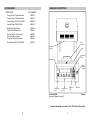
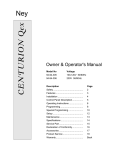
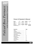
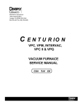
FURNACE DESCRIPTION:
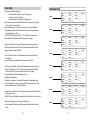
ACCESSORIES:
DESCRIPTION
PART NUMBER
Tongs; 25cm (10") Stainless Steel
Tongs; 30cm (12") Stainless Steel
9390014
9390015
Vacuum Pump; 100-125V; 50/60Hz
Vacuum Pump; 230V; 50/60Hz
9492999
9492410
Side Mounted Work Shelf
Ceramic Side Platform Tray
9492932
9390017
De-Con-Tam Kit; 5 carbon rods
Silver Calibration Coupons
Firing Tray, Round Honeycomb
9490799
9982561
9998813
Service Manual, Q50, Q100, Q200
9363078
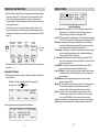
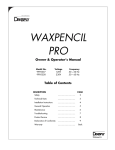
Door
Insulation
Muffle
(Inside)
Door
Start/Stop
Keys
Escape Key
S
ESC
Power
Switch
(On/Off)
S
Start
Stop
1
2
3
F1
F2
F4
F3
4
5
6
7
8
9
0
Enter
Open\Close
Keys
Function Keys
(F1-F4)
Centurion Q200
(See also "Features", page 14)
Digit Keys
(0-9)
Enter Key
Figure 1
* Canadian Standards Association (CSA), TÜV-GS and CE certified.
26
3
PARAMETER DESCRIPTION (CONT.)
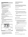
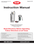
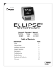
INSTALLATION INSTRUCTIONS:
Experimental Mode
UNPACKING:
Carefully unpack and remove the furnace from its shipping carton.
• Do not lift furnace by the top cabinet assembly.
• Save the carton and other packing material for future use in
transporting the furnace.
• Shipping damage should be reported to the carrier as soon as
detected.
This mode of operation allows the operator to customize firing cycles.
Each cycle has up to 9 segments. However, the first and last segments
are special to include drying and cooling features.
Segment 1 parameters
The furnace shipping carton contains the following:
• One furnace complete with power cord
• Owner & Operator's Manual (this document)
• Side work shelf, Program log book and cards
• Vacuum tubing, connections, and fuses
• Fiber Door Insulation (MUST BE INSTALLED in furnace
before operation, see page 3)
• Ceramic firing trays and ceramic pegs for temperature checks
Temp: This is the temperature before and during the segment 1 firing
cycle
LIFTING AND CARRYING:
• Get a firm footing. Keep your feet shoulder width apart for a stable base.
• Bend your knees. Don't bend at the waist.
• Grip the base of the furnace and lift with your legs.
• Keep the load close to your body and carry the unit to the destination. Keep your
back upright during lifting.
INSTALLATION:
• Remove all packing material from in and around the furnace. The
furnace should be located at least 15cm (6") away from walls, shelves
and heat sensitive materials.
• The furnace should not be located directly under shelves or other airflow
restrictions.
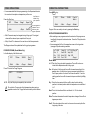
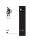
• Vacuum pump connections (see Figure 2, below).
Vacuum
Chamber Vent
Vacuum Pump
Socket
Pos: At the start of a firing cycle the muffle is lowered according to
the position value specified. From this position the muffle is lowered
in steps. A value of zero has no movement. A value of 9 will close
the muffle.
Time: This is the time the muffle stepped to its closed position while the
temperature is controlled at Lo T.
Segment 2 thru 8 Parameters
Rate: This value determines the rate of temperature change of the muffle
Vac%: This value instructs the control how much vacuum to pull.
A value of 100% indicates that vacuum be pulled until the pump
cannot deliver any more and then to turn off the pump.
A value of 101% will instruct the pump to stay on until the release
command is given.
A value of less than 100% will turn off the pump at the appropriate
value.
Hold: This is the time the muffle is controlled at the end of the Rate.
External
Vacuum Pump
Hose Connection
Power Cord
Gas Backfill Port
Manual (Emergency)
Vacuum Release
Rear Panel View, Q200
Figure 2
Temp: This is the temperature at the end of the Rate
Gas: This parameter is programmed either ON or OFF
When programmed ON it allows a gas (when connected to the
back of the furnace) to enter the muffle. The flow can be adjusted by
means of a needle valve during this segment.
• Connect the power cord to a power circuit or receptacle with an
overcurrent protection (circuit breaker or fuse) rating of at least 15
Amps. This circuit should only supply the furnace and pump. Never
use an extension cord.
4
Segment 9 Parameter
Cool: This is the time the muffle is stepped to its open position.
25
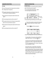
OPERATING INSTRUCTIONS:
PARAMETER DESCRIPTION:
InCer Mode
All the ceramic firing programs have two segments each consisting of a
Rate, a Temperature and a Time parameter.
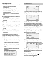
GETTING STARTED:
The following example is for conventional porcelain firing in the Dental
mode, for other operating modes, see page 18.
• Turn on the furnace power switch (see Figure 1, page 3).
• The furnace display will show the test screen:
R1: This parameter determines the rate of temperature change inside
the muffle to reach its first destination temperature
T1: This value determines the temperature inside the muffle at its first
segment
H1: This value determines the time the muffle is controlled at T1
Software
Version
*** Ney Dental Inc. ***
V1.0 f=60Hz, Line AC+, Cycles=0
Press <ESC> to continue
Muffle is off
Motor TEST
Completed
Firing Cycles
• For motor speed timing, the muffle will go up, down, then up again.
R2: This parameter determines the rate of temperature change inside the
muffle to reach its second destination temperature
!
T2: This value determines the temperature inside the muffle at its second
segment
Remove the foam padding from inside the muffle and place the
door insulation in center of door. (See Figure 1, page 3).
Pressing the E S C key will start normal operation
H2: This value determines the time the muffle is controlled at T2
35°C
•
725mm
34:27M
Prog 100
New ->
<Edit>
<Nite>
<Purge>
<Mode>
Program 100 is preprogrammed to remove any accumulated moisture.
It is recommended to run this cycle now and observe the different
stages during the firing cycle. Press the green S start key.
The furnace control now enters the firing mode and heats the muffle
temperature to its LoT=550°C. At that point the muffle travels to its
"Dry" Position (programmable from 0-9, in this case, 2) and continues
to close in small steps for 5 minutes.
Once the muffle is closed a 1 minute "Heat" soak is performed,
followed by a heat increase ("Rate") of 55°C/min to 960°C under
vacuum to remove any moisture. The vacuum pump will turn off once it
reads a steady level but will repump if excess moisture is in the muffle.
(If the furnace does not pull vacuum, a "No Vac" error will occur. See
page 22, "Error Codes"). After a 20 minute soak at 960°C the furnace
enters the cool cycle as the muffle opens.
24
5
OPERATING INSTRUCTIONS:
ERROR CODES:
• Daily Use: Before starting the normal firing process each day allow the
furnace to preheat for 15 to 30 minutes at its low temperature. Alternately running a firing cycle without a load can also be used as a
preheat operation. Preheating the furnace will provide more accurate
and consistent results.
When the furnace is not being used keep the muffle closed. This
prevents the absorption of moisture into the thermal insulation which
reduces vacuum levels when normal firing is attempted. (See "Setup",
page 17).
Current Muffle
Temperature
ESC
Escape
Key
Barometric
Pressure
Program
Time
Program
Number
35°C
725mm
34:27M
Prog 100
New ->
<Edit>
<Nite>
<Purge>
<Mode>
F1
F2
F3
New Program
Number
F4
• The function keys F1-F4 activate different tasks shown on the display in
brackets (< >).
CHANGING PROGRAMS:
• The blinking arrow below the program number indicates a new program
may be entered.
Example: Change current program 100 to program 34.
Key sequence: 3, 4,
(Enter).
35°C
725mm
35:25M
Prog 100
New ->34
<Edit>
<Nite>
<Purge>
<Mode>
Open TC No Vacuum
Over Temp Lo Vacuum
Max. Temp No Muffle
Typical Error Display
Over Temp (Muffle temperature > 1220°C); Possible causes: Shorted
Thermocouple, shorted triac, shorted optotriac on computer
PCB, bad wiring connections, bad computer PCB
Open TC (Thermocouple); Possible causes: TC tip open, bad connection
to TC, bad TC to computer PCB connection, bad computer PCB
Max Temp; Temperature above programmable limit Tmax; Possible
causes: Prog High Limit programmed lower than current parameters, overshoot from high heat rate, same as Err1
No Vacuum; Detected no or little pull; Possible causes: Vacuum pump
not connected (hose and power cord), interference material on
O-ring surface (See figure 2, page 4)
Lo Vacuum; Possible causes: moisture in muffle (run program 100),
poor vacuum pump performance, Press ESC to clear the Err and
continue the firing cycle
Open Muffle: No muffle current detected; Possible causes: Muffle
opened, bad wiring connections to muffle, bad triac
Low AC Voltage; Possible causes: wall socket shared with other loads,
furnace connected with small extension cord, low voltage from
power company
EEPROM error; Microcomputer program memory error; Possible
causes: computer PCB
Wrong TC; Shorted or Reversed Thermocouple (TC); Possible causes:
TC connections reversed at computer board terminals, TC
extension wire shorted against metal structure or cabinet
Motor; Too slow, time to reach up position was greater than 12 sec.
Possible causes: weight on top of enclosure, bent lift mechanism, control PCB failure, Motor connector not connected
Triac; Fires continuously; Possible causes: Triac driver or triac shorted
No Hz; No line frequency detected; Possible causes: computer PCB
The program parameters of program 34 are displayed.
Lo T ->550
Pos. 2
Dry 1:00
Heat 1:00
Rate 55 Hi T 960 Prog 34
Vac%100 Vstp 960
Hold 1:00 Vstp 1:00
Cool 1:00
<Copy>
6
No Hz
TC Wrong
Triac
Motor
EEPROM Lo AC
23
OTHER OPERATIONS:
OPERATING INSTRUCTIONS:
• It is recommended that before programming in the Experimental mode
the user should complete a temperature profile curve.
Press the Start key:
35°C
745mm
Stage 1
Expm 1.9
-=-=-=-=-=-=-=-=-=-=-=-=-=-=-=-=-=-=-=-=-=-=-=<Edit>
<Skip>
Rate 25
Line flickers to
indicate firing
cycle operation.
Current operation is
indicated: Rate or
Hold along with
program parameter.
• <Edit> Parameter may be changed during a firing cycle. The original
values will be restored upon completion of the cycle.
• <Skip> Press F3 to advance to the next rate or hold time parameter.
The Stage number will be updated as the firing cycle progresses.
PURGE PROGRAM: (Dental Mode Only)
In the idle display of the Dental mode:
35°C
<Edit>
725mm
<Nite>
35:25M
<Purge>
Prog 1
New ->
<Mode>
Press F3 to start the Purge Program
550°C
01:30:00 H
Purge
NOTE: Only the Stop key is accepted by the controller.
!
Do not abort a Purge cycle at high temperatures when using a
graphite or carbon rod. Oxygen will react violently with hot carbon.
Press ESC
key.
35°C
725mm
10:20M
Prog 34
New ->
<Edit>
<Nite>
<Purge>
<Mode>
Program 34 is now ready to be ran by pressing the Start key.
EDITING PROGRAM PARAMETERS:
• After selecting a new program number the contents of the program can
be edited to the operator's desired values. Press the F1 key below the
word "Edit".
• It is recommended to fill out the respective screen in the log section
(see page 10) before entering new data.
Lo T ->550
Pos 2
Dry
1:00
Heat 1:00
Rate 55
Hi T 960 Prog 34
Vac%100 Vstp 960
Hold 1:00 Vstp 1:00
Cool 1:00
<Copy>
Dental Mode
Lo T: This is the firing cycle start temperature. The muffle is also controlled at this temperature after a firing cycle.
Pos: At the start of a firing cycle the muffle is lowered according to this
position value. A value of zero has no movement and starts from
the full open position. A value of 9 will close the muffle. From this
starting position the muffle is lowered in steps controlled by the Dry
time.
Dry: This is the time required for the muffle to step from the starting
position to its closed position while the temperature is controlled at
Lo T.
Heat: This is the time the muffle is controlled at Lo T in the closed
position.
Rate: This value determines the rate of temperature change of the muffle in
degrees per minute.
Vac%: This value instructs the control on how much vacuum to pull at the
beginning of the rate.
22
7
OPERATING INSTRUCTIONS:
A value of 100% indicates that the vacuum pump will operate until
the vacuum level stops increasing (lowest reading).
Approximately 1 minute.
A value of 101% will instruct the pump to stay on until the release
command is given.
A value of less than 100% will turn off the pump at the appropriate
vacuum level below full vacuum.
A value of 0% will be an "Air" cycle and not turn on the vacuum
pump.
OTHER OPERATIONS:
Temp -> 25
Pos.
4
Time 0:00
Hi T: This is the high temperature at the end of the Rate held for the Hold
time.
x.y
Next Stage:
<Add>
The first stage in the Expm mode is the muffle closing operation. Press
the F1 key to edit the parameters. Pressing the F4 key adds a second
stage to the program.
Rate -> 25
Vac% 0
Hold 0:00
Hold: This is the time the muffle is controlled at the high temperature (HiT) at the end of the Rate.
Cool: This is the time the muffle is stepped to its open position from the
closed position.
Expm1.1
Temp 25
Gas 0
<End>
Expm1.2
<Add>
Vstp: This value sets the vacuum release temperature during the Rate. If
programmed below the Hi T the vacuum is release at that temperature. If programmed above the Hi T the vacuum is held for all of the
Hold Time.
Use the F2 and F3 keys to edit the parameters. The Rate, Vac%, Hold
and Temp parameters are the same as those used in the Dental Mode.
The Gas parameter, when set to 100%, activates the gas backfill valve. A
low pressure inert gas blanket can be applied to the chamber. The bottom
aluminum door acts as the pressure relief valve. The flow into the chamber
is limited by the needle adjustment valve on the rear of the furnace.
Vstp: When Vstp temp above is set equal to the Hi T then a vacuum
stop time can be set. This is the amount of time during the Hold
time with vacuum.
Pressing the F4 "Add' key adds another stage to the program. Up to 6
more stages can be added. When the program reaches stage 9, the last
stage is the muffle opening (Cooling) operation.
• The blinking arrow after LoT indicates that this parameter can be
changed by means of the digit keys followed by the Enter key. After
the LoT value has been entered the arrow advances automatically to
the next parameter.
• Press F1 to advance to the parameter that needs to be changed
in the F1 column.
• Press F2 for parameters that need to be changed in the F2
•
column.
Press F3 for parameters that need to be changed in the F3
column.
If a parameter is programmed out of range the display will show
the allowed ranges:
Lo T: 25-800°C
Rate: 1-222°C/min
Temp: 25-1205°C
Tmax: 800-1210°C
Prog: 1-100 (1-5, 1-9)
Tcal: 860 - 1060°C
Vac: 0,50...100,101%
Nite: 25-800°C
8
[ESC]: To operate
<Add>: Next Stage
<End>
Temp 25
Expm1.9
Cool-> 1:00
The <End> key can be pressed at any number of stages to limit the
program length.
35°C
<Edit>
745mm
Stage 1
Expm 1.9
New ->
9 indicates that
there are 9 stages
in Program 1.
<Mode>
Pressing the E S C key puts the furnace into the Expm Idle mode. The
display shows the current muffle temperature, chamber pressure, current
stage, and program name.
Pressing one of the 1 - 9 digit keys followed by the
changes to one of the 8 other Experimental programs.
21
Enter key
OTHER OPERATIONS:
OPERATING INSTRUCTIONS:
Pressing the E S C key puts the furnace into the InCer Idle Mode.
COPYING PROGRAMS:
• This function is used to speed up programming when several programs
have similar parameters.
Press F4 to activate the copy program while in the <Edit> display:
35°C
9:18:00H
<Edit>
InCer 1
New ->
Lo T ->550°C Rate 50
Pos 2
Vac%100
Dry
1:00 Hold 1:00
Heat 1:00
Cool 1:00
<Mode>
Pressing one of the 1 - 5 digit keys followed by the
Enter key
changes to one of the 4 other InCer programs. Pressing the Start key
starts the firing cycle for the selected program. The display changes as
indicated below:
35°C
9:18:00H
InCer 1
-=-=-=-=-=-=-=-=-=-=-=-=-=-=-=-=-=-=-=-=-=-=-=R1
<Edit>
Hi T 960 Prog 34
Vstp 960 Copy _
Vstp 1:00
<Copy>
Select new
program
number to
be copied to.
Simply enter the program number to be copied to.
Count down time
in Hours:minutes:
second
Example: Copy Program 34 to Program 1
Key Sequence: 1,
(Enter)
Indication of
current operation
being performed
Pressing the F4 <Mode> key causes the control to display the mode
selection screen.
550°C
725mm
10:20M
Prog 1
New ->
<Edit>
<Nite>
<Purge>
<Mode>
Press the F1 key (edit) to change some of the parameters of prog 1
*** Operating Mode Selection ***
<Dental>
InCer Mode
<InCer>
<Expm>
Expm. Mode (Experimental):
START A FIRING CYCLE:
• The firing cycle of the selected program starts. The cycle timer counts
down.
Press the green start S key. (See figure 1, page 3).
Pressing the F3 key activates the Experimental ( Expm) mode. This
mode of operation allows for the free form construction of multiple stage
firing cycles. These cycles can be any combination of temperatures, ramp
rates, vac or air, and gas backfill parameters. Each program stage is
individually programmable with full atmospheric control.
Nine programs (Expm 1 - 9) are available in the Experimental mode each
with nine stages. The Expm mode programs are numbered as "Expm
x.y". Where "x" is the program number and "y" indicates the stage
number in that program.
20
550°C
725mm
35:25M
Prog 1
-=-=-=-=-=-=-=-=-=-=-=-=-=-=-=-=-=-=-=-=-=-=-=<Edit>
<Nite>
<Skip>
LoT 550
Line flickers to
indicate firing
cycle running.
Indicates the
starting temp.
• <Edit>: Parameters may be changed during a firing cycle. The original
values will be restored upon completion of the cycle.
• <Nite>: Pressing F2 tells the control to enter the "Nite Mode" after
•
completion of the cycle. To cancel this mode, press ESC.
<Skip>: Press F3 to advance the control processor to the next parameter in the cycle.
Examples:
• If waiting for LoT - the dry cycle will start.
• If ramping - the present temperature is the new HiT and
the Hold time is activated.
• If cooling - the muffle closes again and the rate segment
is activated again.
9
OPERATING INSTRUCTIONS:
OTHER OPERATIONS:
STOP A FIRING CYCLE:
• Program stops, muffle opens.
Press the red stop S key. (See figure 1, page 3).
550°C
725mm
10:20M
Prog 1
New ->
<Edit>
<Nite>
<Purge>
<Mode>
In the Idle display, the mode selection icon <Mode> is visible.
NITE MODE:
100°C
<Setup>
NITE
[ESC]
to operate
<Mode>
• In this mode the muffle temperature is controlled by the parameter
•
•
OPERATING MODE SELECTION:
The Q200 has three different modes of operation. The first mode is for
conventional porcelain firing and is called <Dental>. The second mode is
for sintering all ceramic restorations and is called <InCer>. The last mode
is for experimental or longer firing cycles and is called <Expm> for Experimental. The following pages explain the <InCer> and <Expm> modes of
operation.
programmed in <Setup> (Default is set at 100°C, See Setup & Maintenance on page 15). Once this temperature is reached, the muffle
closes.
It is recommended to place the furnace into this mode at the end of the
working day to prevent moisture from entering the muffle.
To return to the operating mode press ESC.
DRY POSITION TEMPERATURE:
Listed are temperatures at the load for various position (Pos) and LoT
settings.
Position:
1 -50
70
80
95
120
135
2 -55
75
85
105
130
155
3 -60
85
100
120
155
180
4 -75
100
120
155
195
230
5 -90
130
160
195
255
290
6 -120
180
240
320
380
470
7 -190
330
420
515
600
675
8 -265
380
480
580
680
780
9 -295
395
495
595
695
790
300
400
500
600
700
Lo T in °C
Example: LoT=457°, Pos=2
Temperature at load: approx: 80°C
800
NOTE: Ambient room temperature variations (heater, fan, etc.) will have a
great effect on the load temperature.
10
35°C
725mm
35:25M
Prog 1
New ->
<Edit>
<Nite>
<Purge>
<Mode>
• Press F4 to select the desired mode:
*** Operating Mode Selection ***
<Dental>
Dental Mode
<InCer>
<Expm>
Pressing the F1 key activates the Dental Mode which is described beginning on page 5.
InCer Mode:
Pressing the F2 key activates the InCer Mode. This mode fires all ceramic
restoration using a non-vacuum two stage process. The process generally
requires hours rather than minutes of firing time. Five programs (InCer 1 5) are available.
T1 -> 120
T2
1120
InCer 1
R1
.3
R2
8.3
H1
0:00
H2
2:00
Each InCer program contains two stages of three parameters each for a
total of six parameters. These programs do not have drying, preheating or
cooling operations. The sinter cycles are all air firing cycles, no vac.
These parameters can be edited using the F1 and F2 keys (see page 7).
T1 is the first stage temperature in Degrees C; R1 is the first stage ramp
rate in degrees C per minute. The ramp rate is programmable from 0.1°C/
min to 222°C/minute (.3 is 3/10 of a degree per minute); H1 is the first
stage hold time in hours and minutes (hh:mm). T2, R2 and H2, are the
same respective parameters for the second stage.
19
Name:
SETUP & MAINTENANCE:
PROGRAM LOG _________________________________
SETUP:
• This function allows the operator to customize operating parameters.
Press F2 to enter the Nite Mode.
35°C
<Edit>
725mm
<Nite>
35:25M
<Purge>
Name:
Lo T _____
Pos ____
Heat __:__
Dry __:__
Rate ____ Hi T _____ Prog 1
Vac% ___ Vstp _____
Hold __:__ Vstp __:__
Cool __:__
Name:
Lo T _____
Pos ____
Heat __:__
Dry __:__
Rate ____ Hi T _____ Prog 2
Vac% ___ Vstp _____
Hold __:__ Vstp __:__
Cool __:__
Name:
Lo T _____
Pos ____
Heat __:__
Dry __:__
Rate ____ Hi T _____ Prog 3
Vac% ___ Vstp _____
Hold __:__ Vstp __:__
Cool __:__
Name:
Lo T _____
Pos ____
Heat __:__
Dry __:__
Rate ____ Hi T _____ Prog 4
Vac% ___ Vstp _____
Hold __:__ Vstp __:__
Cool __:__
Name:
Lo T _____
Pos ____
Heat __:__
Dry __:__
Rate ____ Hi T _____ Prog 5
Vac% ___ Vstp _____
Hold __:__ Vstp __:__
Cool __:__
Name:
Lo T _____
Pos ____
Heat __:__
Dry __:__
Rate ____ Hi T _____ Prog 6
Vac% ___ Vstp _____
Hold __:__ Vstp __:__
Cool __:__
Name:
Lo T _____
Pos ____
Heat __:__
Dry __:__
Rate ____ Hi T _____ Prog 7
Vac% ___ Vstp _____
Hold __:__ Vstp __:__
Cool __:__
Name:
Lo T _____
Pos ____
Heat __:__
Dry __:__
Rate ____ Hi T _____ Prog 8
Vac% ___ Vstp _____
Hold __:__ Vstp __:__
Cool __:__
Prog 1
New ->__
<Mode>
Press F1 to view or change the "Setup" parameters.
100°C
NITE
[ESC]
to operate
<Setup>
<Mode>
Setup parameters can now be reviewed or changed.
*** Setup Parameters***
Tnite -> 100 Tcal 960 Deg. C Audio On
Tmax 1210 Down 10:00 < >
< >
• Tnite - temperature at which the muffle is controlled during the Nite
Mode.
• Tmax - alarm temperature. For extra protection during firing cycle.
• Tcal - calibration temperature at 960°. Increasing this value will increase
•
•
the actual muffle temperature at 960°C by this change.
F3 - toggles °C to °F.
F4 - toggles "key beep" On to Off.
MAINTENANCE:
CLEANING:
•
•
Vacuum dust and dirt from the furnace rather than blow. This will minimize
the amount of airborne dust particles.
Use a soft damp cloth to clean the control panel. Avoid excess water or
solution when cleaning the furnace. Some solutions will attack the panel
or electronics and may cause the furnace to malfunction.
REPLACEABLE FUSES:
• F1: F 250V / 1.0A
18
11
Name:
PROGRAM LOG _________________________________
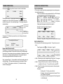
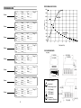
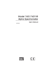
PERFORMANCE CURVES:
1200
Name:
Name:
Rate ____ Hi T ______ Prog 9
Vac% ___ Vstp _____
Hold __:__ Vstp __:__
Cool __:__
Lo T _____
Pos ____
Heat __:__
Dry __:__
Rate ____ Hi T ______ Prog 10
Vac% ___ Vstp _____
Hold __:__ Vstp __:__
Cool __:__
Lo T _____
Pos ____
Heat __:__
Dry __:__
Rate ____ Hi T ______ Prog 11
Vac% ___ Vstp _____
Hold __:__ Vstp __:__
Cool __:__
Lo T _____
Pos ____
Heat __:__
Dry __:__
Rate ____ Hi T ______ Prog 12
Vac% ___ Vstp _____
Hold __:__ Vstp __:__
Cool __:__
Lo T _____
Pos ____
Heat __:__
Dry __:__
Rate ____ Hi T ______ Prog 13
Vac% ___ Vstp _____
Hold __:__ Vstp __:__
Cool __:__
Name:
Lo T _____
Pos ____
Heat __:__
Dry __:__
Rate ____ Hi T ______ Prog 14
Vac% ___ Vstp _____
Hold __:__ Vstp __:__
Cool __:__
Name:
Lo T _____
Pos ____
Heat __:__
Dry __:__
Rate ____ Hi T ______ Prog 15
Vac% ___ Vstp _____
Hold __:__ Vstp __:__
Cool __:__
Lo T _____
Pos ____
Heat __:__
Dry __:__
Rate ____ Hi T ______ Prog 16
Vac% ___ Vstp _____
Hold __:__ Vstp __:__
Cool __:__
Name:
Name:
1100
1000
TEMP (DEG C)
Name:
Lo T _____
Pos ____
Heat __:__
Dry __:__
Max Rate
900
800
700
600
COOL DOWN
(Open)
500
400
300
0
2
4
6
8
10
12
14
16
TIME (MINUTES)
OUTLINE DRAWINGS:
in (mm)
11.5 (292)
14.5 (368)
11.6 (295)
10.5 (267)
7.1
(180)
13.1
(333)
13.0 (330)
Name:
SYMBOL TABLE
!
I
O
- Important
- Alternating current
- On (Supply)
- Off (Supply)
- Hot Surface
5.9 (150)
- Protective
Conductor Terminal
12
19
(483)
6.0 (153)
17.4 (442)
17
1.6 (41)
FEATURES:
Name:
PROGRAM LOG _________________________________
• Three User Modes of Operation:
• Conventional Porcelain Firing: 100 Programs
• Ceramic Sinter: 5 Programs
• Experimental: 9 Programs of 9 Stages each
• High Performance Quartz Spiral Muffle Produces Superior Porcelain
Name:
Lo T _____
Pos ____
Heat __:__
Dry __:__
Rate ____ Hi T ______ Prog __
Vac% ___ Vstp _____
Hold __:__ Vstp __:__
Cool __:__
Name:
Lo T _____
Pos ____
Heat __:__
Dry __:__
Rate ____ Hi T ______ Prog __
Vac% ___ Vstp _____
Hold __:__ Vstp __:__
Cool __:__
Name:
Lo T _____
Pos ____
Heat __:__
Dry __:__
Rate ____ Hi T ______ Prog __
Vac% ___ Vstp _____
Hold __:__ Vstp __:__
Cool __:__
Name:
Lo T _____
Pos ____
Heat __:__
Dry __:__
Rate ____ Hi T ______ Prog __
Vac% ___ Vstp _____
Hold __:__ Vstp __:__
Cool __:__
Name:
Lo T _____
Pos ____
Heat __:__
Dry __:__
Rate ____ Hi T ______ Prog __
Vac% ___ Vstp _____
Hold __:__ Vstp __:__
Cool __:__
Name:
Lo T _____
Pos ____
Heat __:__
Dry __:__
Rate ____ Hi T ______ Prog __
Vac% ___ Vstp _____
Hold __:__ Vstp __:__
Cool __:__
Name:
Lo T _____
Pos ____
Heat __:__
Dry __:__
Rate ____ Hi T ______ Prog __
Vac% ___ Vstp _____
Hold __:__ Vstp __:__
Cool __:__
Name:
Lo T _____
Pos ____
Heat __:__
Dry __:__
Rate ____ Hi T ______ Prog __
Vac% ___ Vstp _____
Hold __:__ Vstp __:__
Cool __:__
with Long Life Characteristics
• Internal Barometer for Automatic Vacuum Control and Calibration.
• Programmable Muffle Dry Position with Continuous Step Movement
•
•
During Dry and Cool Times
1204°C (2200°F) Maximum; 25°C (177°F) Minimum Temperature
Smooth Muffle Movement with Stationary Work Support
• Large Low Heat Loss Viewport; Optimum Viewport Angle Viewing
• "Heat" Parameter Allows Work to be Preheated with Muffle Closed
• Large 10cm (4") Diameter Muffle
• Fast Cool Down for Short Times Between Loads Gives Maximum
Productivity
• Vacuum Release Programmable in Temperature or Time
• Full Program Flexibility; Parameters Changeable During Firing Cycle
• Power Outage Return; Short Power Outages (<30seconds) Do Not
•
•
•
•
Interrupt Cycle Or Cause Loss of Vacuum Due To Outage
Programmable High Limit Temperature Alarm
Nite Mode Temperature
Friendly User Interface; Manual Not Required In Most Applications
Copy Program Key; User Can Copy and Edit Programs Rather Than
Enter ALL Parameters for EACH Program
• Energy Saver "Idle Down Time"; Programmable Timer Closes Muffle but
Maintains Lo Temp
• PURGE Cycle for Muffle Decontamination After the Use of Silver Alloys
• Automatic Temperature and Vacuum Calibration
• Inert Gas Backfill Capability with Adjustable Needle Valve in Expm
Mode
16
13
Name:
PROGRAM LOG _________________________________
Name:
Lo T _____
Pos ____
Heat __:__
Dry __:__
Rate ____ Hi T ______ Prog __
Vac% ___ Vstp _____
Hold __:__ Vstp __:__
Cool __:__
Name:
Lo T _____
Pos ____
Heat __:__
Dry __:__
Rate ____ Hi T ______ Prog __
Vac% ___ Vstp _____
Hold __:__ Vstp __:__
Cool __:__
Name:
Lo T _____
Pos ____
Heat __:__
Dry __:__
Rate ____ Hi T ______ Prog __
Vac% ___ Vstp _____
Hold __:__ Vstp __:__
Cool __:__
Name:
Lo T _____
Pos ____
Heat __:__
Dry __:__
Rate ____ Hi T ______ Prog __
Vac% ___ Vstp _____
Hold __:__ Vstp __:__
Cool __:__
Name:
Lo T _____
Pos ____
Heat __:__
Dry __:__
Rate ____ Hi T ______ Prog __
Vac% ___ Vstp _____
Hold __:__ Vstp __:__
Cool __:__
Lo T _____
Pos ____
Heat __:__
Dry __:__
Rate ____ Hi T ______ Prog __
Vac% ___ Vstp _____
Hold __:__ Vstp __:__
Cool __:__
Name:
Lo T _____
Pos ____
Heat __:__
Dry __:__
Rate ____ Hi T ______ Prog __
Vac% ___ Vstp _____
Hold __:__ Vstp __:__
Cool __:__
Name:
Lo T _____
Pos ____
Heat __:__
Dry __:__
Rate ____ Hi T ______ Prog __
Vac% ___ Vstp _____
Hold __:__ Vstp __:__
Cool __:__
Name:
14
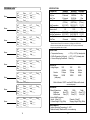
SPECIFICATIONS:
PARAMETER
Low Temperature
Dry Time
Heat Time
Heat Rate
High Temperature
Hold Time
Vacuum Level*
Vac Pull Temperature
Vac Stop Temperature
Vac Stop Time
Cool Time
MINIMUM
25°C (177°F)
0 Seconds
0 Seconds
1°C/Min.
(2°F/ Min.)
25°C (122°F)
0 Seconds
5%
25°C (122°F)
25°C (122°F)
0 Seconds
0 Seconds
MAXIMUM
INCREMENT
800°C (1472°F)
1°C (1°F)
99:59 Min.
1 Sec
99:59 Min.
1 Sec
222°C/Min.
1°C/min.
(400°F/ Min.)
(1°F/min.)
1204°C (22 °F)
1°C (1°F)
99:59 Min.
1 Sec
101%
1%
1204°C (2200°F) 1°C (1°F)
1204°C (2200°F) 1°C (1°F)
Full Hold Time
1 Sec
99:59 Min.
1 Sec
* Special Vacuum Cases: 0% is no vacuum or air firing cycle; 100% is the
maximum vacuum possible, then pump turns off; 101% is pump on continuously
during the programmed vacuum on time.
OPERATIONAL
• Temperature Accuracy:
+/- 3°C (+/- 5.5°F) at steady state
• Muffle Temperature Uniformity: +/- 5°C (+/- 9°F) at steady state
• Vacuum Recycling Dead Band: 30mm Hg
ELECTRICAL
Voltage Ranges:
Currents:
Wattage:
(less pump)
100V
50/60Hz
15 Amps
1500W
120V
50/60Hz
12 Amps
1400W
230V
50/60Hz
6 Amps
1400W
Watts to Maintain 1000°C: less than 400 Watts, muffle closed,
no vacuum pump
MECHANICAL
Exterior Dimensions:
Height
Muffle open
48cm (19")
Muffle closed
33cm (13")
Interior Muffle Dimensions:
Height: 6.3cm (2.5")
Furnace Weight: 21Kg (45lbs)
Width
33cm (13")
33cm (13")
Diameter: 10cm (4")
Shipping Weight: 25Kg (55lbs)
ENVIRONMENTAL
Ambient Operating Temperature: 5 - 40°C
Relative Humidity: Maximum 80%, non-condensing
15
Depth
45cm (17.5")
41cm (16")