1
Model 4145A
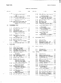
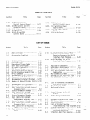
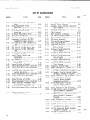
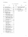
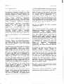
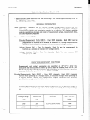
List of Illustrations
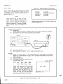
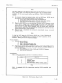
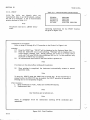
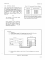
LIST
OF ILLUSTRATIONS
L
Number
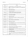
l-l.
l-2.
2-l.
2-2.
2-3.
3-l.
3-2.
3-3.
3-4.
3-5.
3-6.
3-7.
3-8.
3-9.
3-10.
L-
I
3-11.
3-12.
3-13.
3-14.
3-15.
3-16.
3-17.
3-18.
3-19.
3-20.
3-21 .
3-22.
3-23.
3-24.
3-25.
3-26.
3-27.
3-28.
3-29.
3-30.
3-31.
3-32.
3-33;
3-34.
3-35.
b’
+”
3-36.
3-37.
Title
Page
Model 4145A and Accessories
Serial
Number Plate ............
Voltage and Fuse Selection
Power Cable Supplied
Rack Mount Kit .................
....
l-l
l-3
2-2
2-3
.....
...........
Contents
of Section
III ........
Front Panel Features
...........
Rear Panel Features
............
Disc Installation
and Removal . .
Useable Display Area ...........
Operator
Adjustment
............
Byte Size of Arithmetic
Expressions
.................
Source and Measurement
Channels
of the 4145A ................
Simplified
Circuit
Diagram of
One of the Four SMUs ........
Specifiable
Voltage/Current
......................
output
Simplified
Circuit
Diagram of Vs
Simplified
Circuit
Diagram of Ym
Voltage/Current
Output
Specified
by the COMPLIANCE .
Staircase
Sweep Output .........
Relationship
Between VARl and
VAR2 ........................
Relationship
Between VARl and
VARl' .......................
Time Domain Measurement
........
Page Control
Keys ..............
Page Flow and the Relationship
.
MENU Page ......................
CHANNEL DEFINITION Page ........
SOURCE SETUP Page ..............
MEAS & DISP MODE SETUP Page ....
GRAPHICS PLOT Page .............
LIST DISPLAY Page ..............
MATRIX DISPLAY Page ............
SCHMOOPLOT Page
AUTO SEQUENCESETUP Page .......
OUTPUT SEQUENCESETUP Page .....
4145A FILE CATALOG Page ........
...............
OPERATION GUIDE Page ...........
DIAGNOSTICS Page ...............
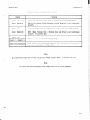
Time Domain Measurement Setup . .
DUT Connection
Using the 1605811.
DUT Connection
Using the
Connector
Plate .............
Example of Guarding
............
Connection
Examples for
Application
Package .........
2-5
3-l
3-2
3-8
3-10
3-11
3-11
3-20
Number
Title
3-38.
3-39.
HP-IB Control
3-40.
3-41.
3-42.
3-43.
3-44.
3-45.
3-46.
3-47.
3-48.
3-49.
Data Output
3-50.
3-51.
Page
Switch ..........
Remote Program Codes and
Parameter Setting
..........
Format
3-86
3-88
3-l 00
............
Status Byte for the 4145A .....
Sample Program 1 ..............
Sample Program 2 ..............
Plot Function
.................
Print Function
................
External
Display
..............
Disc Copy
Head Cleaning
.................
Programs for HP-IB controlled
PLOT Operations
............
Measurement
Ranges and
Resolution
.................
Display/Output
Format .........
3-102
3-105
3-107
3-108
3-110
3-111
3-112
3-l-13
.....................
3-115
3-116
3-119
3-21
3-21
3-22
3-23
3-23
3-23
3-24
3-25
3-26
3-27
3-28
3-29
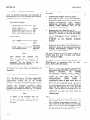
4-l.
4-2.
4-3.
4-4.
4-5.
4-6.
4-7.
4-8.
4-9.
4-l 0.
4-l 1.
4-12.
4-l 3.
4-14.
3-32
3-34
3-38
4-15.
3-42
4-l 6.
4-17.
3-48
3-54
3-57
Test Pattern
for GDU ..........
GDU Connector
Location
........
Display for Key Function
Check.
Voltage Control
Accuracy Test
Setup ......................
Measurement Setup .............
Voltage Measurement Accuracy
Test Setup .................
Measurement Setup .............
Measurement Setup .............
Measurement Setup .............
SU Accuracy Test Setup ........
Measurement Setup .............
MU Accuracy Test Setup ........
Measurement Setup .............
External
CRT X-Y-Z Output
Check Setup ................
Scope Displays
of X-Y-Z
...........
Output (Example)
HP-IB Interface
Test Setup ....
Program Listing
of HP-IB
Interface
Test
4-2
4-3
4-4
4-5
4-6
4-9
4-10
4-13
4-l 6
4-19
4-21
4-22
4-23
4-25
4-26
4-27
..............
4-30
3-59
3-62
3-66
3-67
3-70
3-71
3-74
3-76
3-80
3-82
3-85
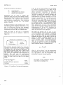
5-l .
5-2.
5-3.
5-4.
5-5.
5-6.
5-7.
5-8.
5-9.
5-l 0.
Test Pattern
for GDU ..........
INTENSITY and FOCUS Locations
.
Connector
Location
............
DC Power Supply Adjustment
Setup ......................
AllR17 Adjustment
.............
5-6
5-6
5-7
5-8
5-9
A5Jl Check ....................
5-10
Check Point Locations
.........
Sample Hold Switch AC Offset
Adjustment
Setup ...........
AC Offset
Adjustment
..........
Check/Adjustment
Point
Locations
..................
5-10
5-11
5-12
5-12
V
~
-_
--
-
_---
__