1
~···io·
1975
Scorpion
Super
Stinger
Service Manual
Engine Section
1
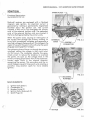
SERVICE MANUAL- 1975 SCORPION SUPER STINGER
ENGINE SYSTEM
Functional Description:
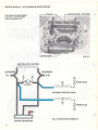
2-CYCLE ENGINE FUNDAMENTALS
The Rockwell 2-cycle air-coo led gasoline engine,
particularly the axial fan-cooled twin cylinder
engine, has become very popular today for
snowmobiles. It is uniquely qualified for this application because of its high power output, light
weight and ease of lubrication, with fewer
moving parts than other conventional 2-cycle
and 4 -cycle engines.
INTAKE
However, in order to get the best possib le use
and ensure that it retains its high degree of
dependability and endurance, it must receive
proper care and maintenance. Therefore, it is
necessary for us to know something about the
basic fundamentals of . this engine and how it
functions.
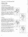
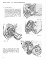
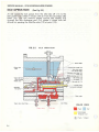
OPERATION
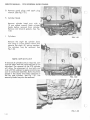
The Rockwell 2-cycle Twin Cylinder engine is of
the loop-scavenged third port type, the most
wide ly used design today. It uses a mixture of
gasoline, oi l and air for combustion, lubrication
and cooling. It fires on every stroke of each
piston. There ore two power strokes for every
revolution of the crankshaft.
0
EXH/UST
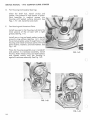
As the piston moves upward in the cylinder it
draws the fuel/air mixture into the crankcase
through the intake manifold while at the same
time compressing fuel that has been forced into
the combustion chamber. See Fig. 1-1 A.
TRANSFER
As the piston nears top dead center the spark
plug is fired and the compressed fuel/air mixture burns and expands thereby forcing the
piston downward on a power stroke.
As the downward stroke of the piston turns the
crankshaft, it also starts to compress the
fuel/air
mixture
in
the
crankcase
and,
simultaneously, opens the exhaust port and
closes the intake port. See Figs. 1- 1 B & C.
1-2
FIG. 1-1
SERVICE MANUAL· 1975 SCORPION SUPER STINGER
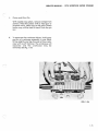
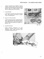
After the exhaust port is fully open and the intake port is fully closed, further piston travel
starts to open the transfer ports. The compressed fuel/air mixture from the crankcase
then travels up the transfer ports and into the
combustion area.
After most of the burned exhaust gases have
left the cylinder, an incoming charge of fuel/air
mixture scavenges the combustion area giving it
a fresh charge and the cycle is then repeated.
SeeFig.l-1 D.
Because lubrication is dependent on the m1xmg
of oil and fuel, it is extremely important that
good quality oil and gasoline are properly
mixed. The proper ratio of oil to gasoline will
prevent possible engine overheating, piston or
cylinder scoring, or eventual engine seizure.
Too much oil and not enough gasoline can lead
to incomplete combustion, fouled plugs, carbon
build-up and muffler clogging.
l -3
SERVICE MANUAL· 1975 SCORPION SUPER STINGER
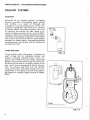
EXHAUST SYSTEMS
SELECTION
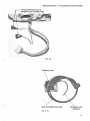
Selection of an exhaust system (including
exhaust manifold, intermediate pipes, elbows
and muffler), is a result of thorough test
procedures involving measurement of fuel consumption, horsepower and noise level. Contrary
to popular belief, the exhaust system is not only
for quieting the engine, but also serves to increase horsepower output (by as much as 25%).
Changes made to the original equipment exhaust
system by changing any component in the system
can result in loss of power and/or severe engine
damage. For these reasons, intermediate lengths
of pipe between the cylinder and the muffler are
particularly critical.
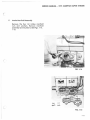
Donaldson
TUNED MUFFLERS
FIG. 1·2
Tuned mufflers allow the engine to exhaust its
spent charge into an adequate volume and
properly matched muffling system. More important, the mufflers that are tuned, incorporate
designs that suck the exhaust gas from the cylinder allowing fuel and air to rapidly replace it and
also "cram" over-scavenged fuel and air mixture
from the exhaust pipe back into the cylinder
using sound waves and sound energy. This is accomplished at the speed of sound which allows
the engine to produce higher torque at higher
RPMs.
n
Tuning
Courtesy of Dona l dson Muffler Co
)
FIG. 1·3
1-4
SERVICE MANUAL· 1975 .SCORPION SUPER STINGER
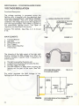
HOW TUNING WORKS
The megaphone effect of the expanded intake
tube scavenges exhaust gas from the cylinder
allowing rapid replacement of the fuel/air mixture from the crankcase. Reflected sound waves
and sound energy stop over-scavenging and
return fuel/air mixture to the cylinder. It gives a
supercharging effect even though it operates
from the exhaust rather than the intake side.
Over-scavenging is also retarded by moderate
muffler back pressure. Silencing is accomplished
after power is maximized by acoustical packing in
the resonator outlet tube plus chambering and
baffling which gives an effective 2-pass muffler
design.
1·5
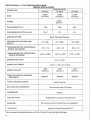
SERVICE MANUAL- 1975 SCORPION SUPER STINGER
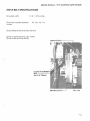
TABLE OF SPECIFICATIONS
ENGINE MODEL
DESCRIPTION
2F 400-8
2F 440-3
BORE
2.658"
(67.5mm)
2.559"
( 65.0mm)
COMPRESSION RATION (actual)
428
398
428
12.5:1
12:1
12:1
IGNITION SYSTEM
LIGHTING COIL VOLTAGE AND
OUTPUT
Bosch Flywhee l Magneto
12V 75W
12V 150W
12V 150W
*TIMING BEFORE TDC (CENTRIFUGAL
WEIGHT ADVANCED)
. 102 - .112
.102-.112
TIMING BEFORE TDC (CENTRIFUGAL
WEIGHT RETARDED)
.0 18" to .020"
.018" to .020"
. 102- . 112
.0 18" to .020"
BREAKER POINT GAP
.014"to .0 16"
SPARK PLUG THREAD
14mm. x 1.25 - 3/4 " reach
SPARK PLUG GAP
.020"
(0.5mm .)
.020"
(0.5mm.)
.020"
(0.5mm.)
SPARK PLUG-BOSCH (ORIGINAL
EQUIPMENT)
W260T2
W260T2
W260T2
TYPE OF ENGINE COOLING
ROT A TION O F CRANKSHAFT
CARBUR ETOR
FUEL/OIL RATIO
GASOLI N E
TYPE OF O IL
Axia l Flow Fan
Counterclockwise (PTO side)
Wa lbro
As Specified on Scorpion Oil Conta iner
95 octane, m i n imum (lead free not acceptab le)
Special 2-Cycle Snowmobi le Oil
* Do not exceed indicated advance, as this will result m severe engme damage.
1-6
2.658"
(67.5mm)
2.362"
(60mm)
STROKE
DISPLACEMENT IN cc
2F 440-8
J
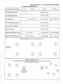
SERVICE MANUAL- 1975 SCORPION SUPER STINGER
TABLE OF SPECIFICATIONS
-8 -9
TORQUE SPECIFICATIONS
CYLINDER HEAD NUTS
2F-440-3
19
2F-440-5
2F-400-6
28 to 32 ft./lbs.
16 to 18 ft./lbs.
CYLINDER BASE NUTS
44 to 50 ft./lbs.
FlYWHEEL NUT
56 to 72 ft./lbs .
56 to 72 ft./lbs.
INTAKE MANIFOLD NUTS
16 to 18 ft./lbs.
FAN HOUSING SCREWS
16 to 18 ft./lbs.
FAN WHEEL NUT
22 to 24 ft./lbs.
RING GEAR SCREWS (6mm.)
6 to 7 ft./lbs.
not applicable
not applicable
RING GEAR SCREWS (8mm.)
10 to 12 ft./lbs.
not applicable
10 to 12 ft./lbs.
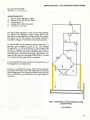
Tightening Sequence for Cylinder Base Nuts
PTO SIDE
0
0
8
0
0
G)
0
8
Tightening Sequence for:
Cylinde r Head Nuts, Fan Housing, Ring Gear Flange, Intake Manifold
and Recoil Starter Clamps
8
0
0
0
0
0
'74 - '75
290s
340s
AI I previous
models
'74- '75
400s
440s
0
®
G)
®
CD
1-7
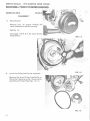
SERVICE MANUAL - 1975 SCORPION SUPER STINGER
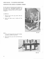
ROCKWELL TWIN CYLINDER ENGINES
MODELS 2F-400-.8
2F-440-8
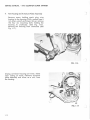
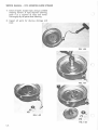
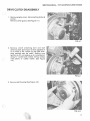
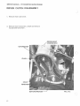
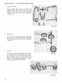
DISASSEMBLY
A.
Recoil Starter
Remove four (4) screws holding the
recoil assembly to the fan housing.
See Fig. 1-4.
See pages 1-28 A, B, C for recoil starter
disassembly.
FIG. 1-4
A
(.:
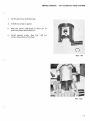
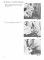
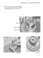
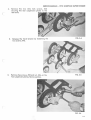
B.
Lower Fan Pulley and Carrier Assembly
FIG. 1-5
Remove the three (3) hex head bolts on
the carrier. Remove carrier, lower pulley
assembly and V-belt. See Figs. 1-5, 1-6.
FIG. 1-6
l-8
SERVICE MANUAL · 1975 SCORPION SUPER STINGER
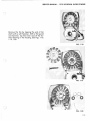
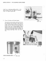
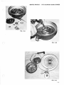
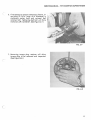
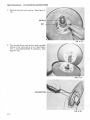
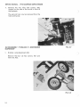
C.
Upper Fan Belt Pulley Assembly.
Insert a 3/16" dri l l or a suitable punch
through the indexing hole into the impeller body. With a 17 mm socket
wrench, remove the fan nut, lock
washer, pulley halves and spacers. See
Figs. 1-7,1 -8 , 1-9.
FIG. 1-7
FIG. 1-8
c
FIG. 1-9
1·9
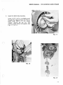
SERVICE MANUAL - 1975 SCORPION SUPER STINGER
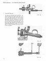
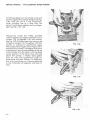
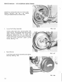
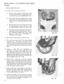
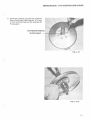
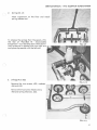
D.
()
Flywheel Magneto
Remove the crankshaft nut using a 27
mm socket wrench . Pull th e flywheel by
attaching flywheel puller 444-31-843-2 to
the flywheel flange using bolts provided.
Screw the three bolts through the puller
into the flange and tighten evenly. With
a socket wrench, tighten the puller bolt
until the flywheel loosens on the
crankshaft. See Figs. 1-10, 1-11, 1-12, 113.
FIG. 1-10
Q.
FIG. 1-11
FIG. 1-12
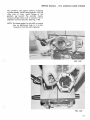
NOTE: It is important that care is taken
to remove the positioning key in crankshaft before attempting to remove the
flywheel assembly. Failure to do this
could result in damage to advance
mechanism.
FIG. 1-13
1- 10
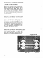
SERVICE MANUAL · 1975 SCORPION SUPER STINGER
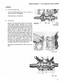
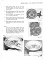
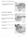
E.
Intake Manifold Assembly
Remove the four (4) intake manifold
nuts and washers. Remove manifold
assembly and insulators. See Figs. 1-14,
1-15.
FIG. 1-14
.0,0
•-'•,;<i* :
oo
00
FIG. 1-15
1-l l
SERVICE MANUAL - 1975 SCORPION SUPER STINGER
F.
Fan Housing and Armature Plate Assembly
Remove screw holding spark plug wire
bracket to fan housing. With a socket type 5
mm Allen wrench and impact driver, remove
the four (4) mounting bolts holding fan
housing to crankcase. (See Fig. 1-16).
Remove fan housing from crankcase (See
Fig. 1- 17).
FIG. 1-16
Unplug connector housing coil wires. (Note
color coding of wires.) Remove armature
plate assembly and wires, as a unit, from
fan housing.
FIG. 1-17
1-12
)
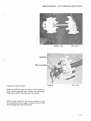
SERVICE MANUAL · 1975 SCORPION SUPER STINGER
n
Remove the fan by tapping the end of fan
shaft with a soft hammer. With a flat punch
and hammer, tap the inner race of the furthest bearing in the housing. See Figs. 1-18,
1-19, 1-20 .
FIG. 1-18
FIG. 1-19
(
'\..._
FIG. 1-20
l-13
SERVICE MANUAL - 1975 SCORPION SUPER STINGER
G. Remove spark plugs with spark plug
wrench. (See Fig. 1-21.)
H. Cylinder Heads
Remove cy linder head nuts
13 mm socket wrench. Mark
heads before removal from
Remove and discard gaskets.
1-22.
I.
with a
cylinder
cylinder.
See Fig.
Cylinders
FIG. 1-21
Remove the e ight (8) cylinder base
nuts using a 13 mm socket wrench and
remove the eight (8) spring washers.
The cylinders may be removed. See
Fig. 1-23.
NOTE: IMP 0 R TAN T
If removal of cy linders only is required, care
must be taken that the crankcase seal is not
disturbed. The removal of the PTO cylinder
will allow the placement of two bolts and
nuts with flat washers to apply constant pressure to crankcase assembly. Bolts should be
placed in the cen t er two holes (adjacent to
the fan side cylinder). See Fig. 1-31. The
second cylinder may now be removed.
FIG. 1-22
FIG. 1-23
1-14
SERVICE MANUAL · 1975 SCORPION SUPER STINGER
r
J.
Piston and Wrist Pin
With needle nose pliers, remove
pistons. Heat the piston with a
propane torch. Heat only to the
piston may still be held in hand.
out.
K.
circlips from
heat gun or
point where
Push the pin
To separate the crankcase halves, hold upper
portion of crankcase assembly in one hand,
lifting slightly and tap the end of the crankcase with a soft hammer. The crankcase will
separate and the crankcase may be
removed. See Fig. 1-24.
n
\
..
.,
.
1· ("""'!)... ·i'
FIG. 1-24
c
1-15
SERVICE MANUAL • 1975 SCORPION SUPER STINGER
L.
Crankshaft Bearings
To remove crankshaft end bearings, use
bearing puller 444-31 -807-0. See Figs. 1-25,
1-26, 1-27. Slip the puller half shells around
the outer bearing race and around puller
assembly. Slide the retaining ring over the
half shells. Using two (2) 27 mm wrenches,
turn the center bolt clockwise with one
wrench and use the second wrench to hold
the puller body. Before removing the PTO
side crankshaft bearing, insert a 1/2" 20 UNF
bolt, 1/2" long, to protect the internal thread
of the crankshaft.
FIG. 1-25
FIG. 1-26
FIG. 1·27
1-16
SERVICE MANUAL • 1975 SCORPION SUPER STINGER
ASSEMBLY
(
A.
Crankshaft Bearings.
Heat crankshaft bearings in oil (or oven) to
approximately 180 degrees.
Slide bearing on crankshaft.
B.
(
Crankcase.
Inspect and clean both halves of crankcase.
The proper sealant material such as Permatex Hy-Tack Spray should be now sprayed
on crankcase sealing surfaces. See Fig. 1-29.
Before installing crankshaft into crankcase
lower half of it will be necessary that all
bearing outer surfaces be wiped clean of
foreign material so that proper sealing will
occur. After installing PTO thrust washer and
oil seal (inside groove of oil seal coated with
light grease) place the crankshaft carefully
into the lower crankcase half and properly
position all components. See Figs. 1-30.
Placement of the upper crankcase half may
now be made. Be certain that the center seal
is lined up with the crankcase split line.
FIG. 1-28
Tap upper crankcase half to seat with lower
half.
FIG. 1-29
FIG. 1-30
l-17
SERVICE MANUAL · 1975 SCORPION SUPER STINGER
J
Install two crankcase holding bolts in the
center holes of the PTO side of crankcase.
(Fig. 1-31) Tighten finger tight.
C.
Piston , Cylinder and Cylinder Heads
FIG. 1-31
The pistons must be clean and free from carbon deposits and the piston rings must fit
freely in their grooves. Rings are marked for
proper side up. The arrow on the crown of
pistons must point toward exhaust side of
engine. Piston pins, needle bearings, check
plates and circlips may now be installed, according to the procedure below. (Always use
new circlips.) See Figs. 1-32, 1-33, 1-34, 1-
()
35.)
FIG. 1-32
CIRCLIP OPENING HERE---' FIG. 1-33
1· 18
J
SERVICE MANUAL · 1975 SCORPION SUPER STINGER
1.
Oil the piston pin end bearings.
2.
Install one circlip in piston.
3.
Heat the piston sufficiently to allow pin to
push into piston and install pin.
4.
Instal l second circlip. (See Fig.
correct orientation of circlips.)
1-33 for
0
FIG. 1·34
FIG. 1-35
1-19
SERVICE MANUAL · 1975 SCORPION SUPER STINGER
In stall base gaskets on th e cy lind er studs and
position against the cy linder flanges (see Fig.
1-36). With the use of a ring compressor,
lower cy linders one at a time over the
pistons . In stall base washers and nuts finger
tight. See Fig. 1-37, 1-38.
Temporarily install the intake manifold
without gaskets and tighten manifold nuts to
sixteen (16) to eighteen (18) foot pounds.
See Fig. 1-39. Cy lind er base nuts may now be
torqued to sixteen (16) to eighteen (18) foot
pounds as outlined on specification page.
The proper piston height can be measured at
the top of the cylinder . The edge of the crown
of the piston must not protrude above the top
of th e cylinder with the piston in the top dead
center position. If the piston does protrude
above the cylinder, a thicker base gasket
must be used. See specification page for
dimensions and color coding. It is important
that only one cylinder at a time be adjusted
or the crankcase will separate and lose it's
seal.
FIG. 1·36
FIG. 1-37
(
FIG. 1-38
l -20
SERVICE MANUAL • 1975 SCORPION SUPER STINGER
c
Oil cylinders and pistons before installing
cylinder heads. Install head gaskets with the
wide side of inner metal flange of the
gaskets up toward the cylinder heads.
Torque cylinder head nuts to sixteen (16) to
eighteen (18) foot pounds. (See Fig. 1-40) .
NOTE : The head gasket for the 400 cc engine
has an additional hole in it to distinquish it from the 440 cc gasket.
)
FIG. 1-39
c
FIG. 1-40
1-21
SERVICE MANUAL . 1975 SCORPION SUPER SnNGER
D.
Fan Housing and Impeller Bearings
)
Clean fan shaft hub. Install circlips and
spacer. Use grease to hold spacer in place.
Pack bearings in medium grease into
housing with sealed surface outward. See
Figs. 1-19, 1-20. Install fan and shaft.
E.
Fan Housing and Armature Plate.
Install new seal in fan housing. Lubricate the
inner groove of the oil seal with a light
grease. See Fig. 1-41.
Install new o-ring and apply sealant material
around o-ring surface (see Fig. 1-41 ). Install
the armature plate wires through hole in fan
housing and install armature plate with hold
down screws, washers, and lockwashers. See
Fig. 1-42.
Place fan housing assembly over crankshaft
and position to crankcase assembly. Install
the four Allen head screws and lockwashers
and tighten evenly until fan housing is
against crankcase assembly. See Fig. 1-43.
FIG. 1-41
J
W\
·~
FIG. 1-42
FIG. 1-43
l-22
SERVICE MANUAL · 1975 SCORPION SUPER STINGER
Torque to sixteen (16) to eighteen (18) foot
pounds. Connect ignition wires to externa l
ignition coil and to connector housing. Check
ground wires for proper position. Install
ignition cable bracket to fan housing.
F.
Intake Manifold
Install spacers, gaskets and intake manifold
(Fig. 1-44). Torque nuts even ly to sixteen
(16) to (18) foot pounds.
G.
Upper Fan Pulley Assembly
Install the tapered washer. In stall pulley half,
shims, second pulley half, tapered washer,
lock washer and nut. Use 3/16" drill bit or
punch to hold fan assembly and tighten nut.
See Fig. 1-45.
~
;r•~
oo
'00
FIG. 1-44
H.
(
Flywheel Assembly
Check advance mechen ism for free
operation, lubricate inside cam surface
(Grooved area). Slide assembly over
crankshaft and align key ways.
(
l -23
SERVICE MANUAL · 1975 SCORPION SUPER STINGER
Install key, lockwasher and nut in that order.
Tighten securely. See Fig. 1-46. Follow
Timing Procedure Section as next step.
I.
Lower Fan Pulley Assembly
FIG. 1-46
Install pulley half, belt, second pulley half,
recoil carrier, lockwashers and bolts evenly
while rotating crankshaft. The proper belt
deflection should be 1/8" on each side.
Proper adjustment can be made by adding or
removing shims between upper pulley
halves. See Fig . 1-47.
J.
Recoil Starter
Install the recoil starter assembly and tighten
securely. See Fig . 1-48.
FIG. 1-47
f
FIG. 1-48
l -24
SERVICE MANUAL - 1975 SCORPION SUPER STINGER
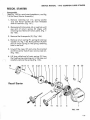
RECOIL STARTER
(
Disassembly
(See Fig. 1-49 for recoil start breakdown, and Fig.
1-50 for Recoil Starter Assembly.)
1. Remove retaining nut {11), spring washer
{12) and Thrust washer {8) from threaded
shaft of reel hub. (Fig. 1-5 1).
2. Manipulate friction plate (4) on reel hub until
eye end of return spring (9) aligns with
retaining slot. Remove friction plate. (Fig. 152, 1~ 53).
3. Remove the three pawls {3), (Fig. 1-54).
4. Remove return spring (9), spring {6) and cup
washer (7). Fig. 1-53. Note position of plain
end of return spring in the spring retaining
hole in reel hub.
5. Unwind the rope; lift and untie the knotted
end from center hub of reel, remove reel (2).
(Fig. 1-55).
n
6. Lift long rolled end of main spring (5) from
the fixed spring retaining pin in the case and
carefully remove the spring (Fig. 1-56).
15
L_
16 17 11
)
~~ I
12
8 21 4
9
6
7
3
2
10
18
19
20
I,~
~,~-.............
Recoil Starter
14
3
14
13
3
5
FIG. 1-49
1-25
SERVICE MANUAL - 1975 SCORPION SUPER STINGER
7. Clean all parts, except rope, usi ng a suitable
cleaning solvent. If rope requires cleaning,
wash it in a so lution of soap and water.
Thoroughly dry all parts after cleaning.
)
8. Inspect all parts for obvious damage and
wear.
FIG. 1-50
FIG. 1-51
FIG. 1-52
1-26
SERVICE MANUAL • 1975 SCORPION SUPER STINGER
(
FIG. 1-54
FIG. 1-55
FIG. 1-56
1-27
1975 SCORPION SUPER STINGER
SERVICE MANUAL
As•erbly
·
1. Replace defective parts.
2. In sta ll main spring as foll ows:
a.
Secure main spring winding tool, part
number 43-0797-60, or equivalent tool,
circu lar end up, in a su itable bench vise.
Start with the long rolled end of main
spring (5) and wind spring into circular
end of tool in a clockwise direction. (Fig.
1-57).
r
dL
Remove tool from vise. Grasp the tool by
its handle and lower the tool, with
spring installed, into case ( 1) (Fig. 1-58).
Secure the long rolled end of spring over
the fixed spring retaining pin. (Fig. 159). Remove winding tool (Fig. 1-60) .
Apply a light film of Lubriplate, or
equivalent, to spring.
FIG. 1-57
3. ~ecure case, open side up, in bench vise.
4. ~ie a knot at one end of the rope. Secure
(
notted end in the center of reel (2). Pull
lope taut and wind entire rope around reel in
Jn anti-clockwise direction until the free end
~~~J~udes through the notched section of the
5 . .tpply a light film of Lubriplate, or
equivalent, to center hub of case and install
the reel. Push down and rotate reel in an
9nti-clockwise direction until the hook en~ages with the free end of main spring. Tension will be felt when reel and spring are proj erly engaged. (Fig. 1-61, 1-62).
FIG. 1-58
6. ~otate reel a maximum of three complete
rns in an anti-clockwise direction. Do not
xceed three turns; hold reel in this position
and feed free end of rope through case at the
rope guide hole. Install rope guide. Loosely
knot the rope to prevent recoil.
7. Apply a light film of Lubriplate or equivalent
to pawls (6) and install them on the reel in
the pawl retainers. (Fig. 1-63). (See Fig. 1-49
for part identification numbers.)
8. Instal l cup washer (7) flat side down, spring
(6) and return spring. Ensure that plain end
of return spring is properly engaged in the
retaining hole in reel hub.
1-28
FIG. 1-59
SERVICE MANUAL . 1975 SCORPION SUPER STINGER
/
9. Install friction plate (5) over reel hub.
Manipulate plate until eye end of return
spring engages and l ocks crosswise in
retaining slot.
10. Rotate friction plate until the three notches
are a l igned with paw ls when paw ls are at
the recoil position.
11 . Install flatwasher (8), lockwasher (12) and
nut (11 ). Tighten nut securely.
12. Un ti e the temporary knot in free end of rope
and in stall the rope handle. Tie a permanent
knot and fit handle secure ly.
FIG. 1-60
13. Check st arter for proper opera ti o n . When
handle is pu ll ed outward , pawls shou ld move
outward.
NOTE:
If main spring . is to be installed with out th e
()
use of a spring winding tool, wind main
spri ng into case in an anti-clockwise direction. Clockwise installation o n the winding
too l is necessary to ensure correct anticlockwise insta ll ation of the spring when tool
is placed upside down in the case.
FIG. 1-61
FIG. 1-62
FIG. 1-63
l -29
SERVICE MANUAL - 1975 SCORPION SUPER STINGER
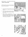
TIMING PROCEDURE
NOTE : Recoil starter, carrier, lowe r pulley assembly and spark plugs should be removed before
beginning timing procedure.
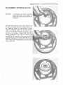
A.
Install the dial indicator assembly into spark
plug hole of No. 1 cylinder (P .T.O. side). See
Fig. 1-64.
B.
Attach negative lead of ohmmeter to engine
ground. Attach positive lead of ohmme ter to
No. 1 cylinder terminal in connector housing.
See Fig. 1-65.
C.
FIG. 1-64
Rotate flywheel
counterclockwise until
points are on the high side of cam on No. 1
cylinder. Points are at maximum open position observed through opening in flywheel.
Check gap with wire gauge and adjust to
.015 if necessary. See Fig. 1-66.
u
FIG. 1-65
CJ
FIG. 1-66
1-30
SERVICE MANUAL - 1975 SCORPION SUPER STINGER
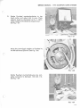
(
D.
Rotate flywheel
dead center and
se lector knob on
meter needle will
See Fig. 1-67.
counterclockwise to top
adjust dial to zero. Place
ohmmeter to R x 1. Ohm indicate a closed circuit.
FIG. 1-67
Move the centrifugal weights in flywheel to
the full advanced position. See Fig. 1-68.
FIG. 1-68
Rotate flywheel counterclockwise one complete revolution to between . 102 and . 112.
See Fig. 1-69.
FIG. 1-69
1-31
SERVICE MANUAL - 1975 SCORPION SUPER STINGER
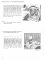
At this point the breaker points for No. 1
cylinder shou ld open. (Break contact) This
will show on the ohmmeter. Needle will
move to the left. If this does not occur, the armature plate needs adjusting. This is accompl i shed by loosening the hold-down
screws and turning plate either left or right
whil e observing needle action. With proper
positioning, needle should move to left with
slight movement of armature plate and
flicker back with opposite plate movement.
Tighten hold-down screws securely. Re-check
procedure. See Fig. 1-70.
NOTE:
In Fig. 1-70 flywh ee l ha s been removed for
clarity of illustration.
FIG. 1-70
n
E.
Remove dial indi cator assembly and install in
No.2 cy lind er (fan side). See Fig. 1-71.
Attach positive lead of ohmmeter to No. 2
cylinder terminal in connector housing.
Rotate flywheel counterclockwise to top
dead center. Set dial indicator to zero. Again
move centrifugal weights in flywhee l to full
advanced position. Rotate flywhe ·~l coun terclockwise while watching di al mdicator.
The needle must make one ful l revolution
and stop at between . 102 and .11 2. At this
point, needle should move to left indicating
point contact (closed). If this does not occur,
points need slight adjustment. Re-check
procedure.
FIG. 1-71
1-32
SERVICE MANUAL · 1975 SCORPION SUPER STINGER
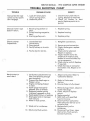
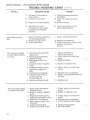
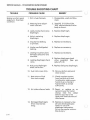
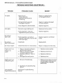
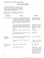
TROUBLE SHOOTING CHART
TROUBLE
PROBABLE CAUSE
REMEDY
Manual starter rope
comes out but pawls
don't engage.
1. Lack of friction plate
return spring action .
2. Defective pawls .
1. Check friction plate returnspring. Replace as r equired.
2. Check for br.o ken or bent
pawls. Replace pawls as required.
Manual starter rope
doesn't return.
1. Recoi l spring broken or
bent.
2. Pulley housing warped or
bent.
3. Starting pulley worn.
1. Replace spr ing.
Electric starter
inoperative.
1. Loose electri cal
connections.
2 . Poor ground.
3. Faulty battery or circuits.
4. Faulty electric starter.
n
Hard to start or
won't start.
1. Carburetor adjustments too
lean (not allowing enough
gas to engine).
2. Inoperative diaphragm or
flapper valve.
3. Engine not being choked
to start.
4. Spark plugs improperly
gapped, d i rty or broken.
5 . Magneto breaker points
improperly gapped or dirty.
6. Head gasket blown or leaking.
7. Empty gas tank or improper
fuel mixture.
8 . Water in fuel system.
9. Weak coil or condenser.
10. Obstructed fuel system.
2. Replace housing.
3. Replace pulley.
1. Retighten connections.
2. Secure ground connection.
3. Check, recharge or replace
battery.
4. Check starter solenoid.
Repair or r ep lace.
5. Inspect starter motor for
evidence of moisture and
broken or worn brushes . Dry
out as necessary.
6. Check starter switch . Replace
if required.
7. Check harness or connector
for broken wire. Repair or replace.
1. Adjust carbu r etor. Refer t o
Carburetor Section
2. Refer to Carburetor
Section.
3. Ensure choke is fully closed.
4. Remove plugs. Clean, adjust or
install new plugs.
5. Clean, adjust or replace
points.
6. Replace gasket.
7. Refill tank with specified
fuel/oil mixture.
8. Drain fuel from carburetor.
Add carburetor de-icer as required to fuel.
9. Replace faulty coil or
condenser.
10. Disconnect fuel lines - clear
obstruction. Flush system.
Connect fuel lin es .
1-33
SERVICE MANUAL - 1975 SCORPION SUPER STINGER
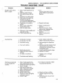
TROUBLE SHOOTING CHART
TROUBLE
13. Engine not timed properly.
14. Secondary wire not
connected or spark plug
protector not installed
properly.
Impos sible to adjust
idle.
Mi ss ing at low speed
or won't idle smoothly
or slowly.
l. Spark retarding mechanism
not working properly.
2. Pistons or rings worn.
3. Faulty carburetor.
l. Incorrect carburetor idle
2.
3.
4.
5.
6.
7.
8.
Missing at high speed
or inte rmitt e nt spark.
adjustment.
Spark plugs improperly
gapped or dirty.
Head gasket blown or
leaking .
Loose or broken magneto
wire s.
Magneto breaker points
improperly gapped or
dirty.
Weak coil or co nden ser.
Improper fuel mixture.
(1) Too much oil
(2) Too littl e oil
Lea king crankshaft seal.
l. Spark plug s improperly
2.
3.
4.
5.
6.
7.
1-34
REMEDY
PROBABLE CAUSE
11. Air leak in crankcase or
inlet system.
12. Primary wire broken.
gapped or dirty.
Loose or broke n magne to
wires.
Magneto breaker points
improperly gapped or dirty.
W ea k coil or condenser.
Heat rang e of spark plug
incorrect.
Leaking head gasket.
Engine improper ly timed.
(coNr.)
()
11. Check crankcase pressure
(3 -6 PSIG)
12. Repair or replace primary
wire.
13. Re-time engine.
14. Secure secondary wire or
spark plug protector.
l. Repair retard mechanism.
2. Replace as necessary.
3. Check carburetor, check valve.
Refer to Carburetor
Section.
l. Adjust idle-Refer to
Carburetor Section.
2. Clean, adjust or insta l l new
plugs.
3. Replace gasket.
n
4. Repair or replace wires.
5 . Adjust, clean or install new
points.
6. Replace coil or condenser.
7. Refuel, using specified fu e l/oil
mixture.
8. Replace seal.
l. Clean, adjust or install new
plugs.
2. Repair or replace wires.
3 . Clean, adjust or install new
points.
4. Re place coil or condenser.
5. Install specified spark plugs.
6. Re place head gasket.
7. Re-time engine.
()
SERVICE MANUAL · 1975 SCORPION SUPER STINGER
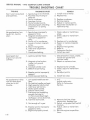
TROUBLE SHOOTING CHART
(
TROUBLE
Coughs, spits, slows
down, surges
1. Idle or high speed jets too
lean.
2. Leaking gasket flange.
3. Inlet control leve l set too
low.
4. Pulsation line obstructed.
5. Fuel pump not supplying
enough fuel due to:
(1} Punctured diaphragm.
(2) Inoperative flapper valve.
6. Crankcase not properly
sealed.
7. Idle or main carburetor
nozzle obstructed.
8. Fuel line obstructed.
9. Carburetor inlet needl e and
seat obstructed.
10. W elch plug leaking.
c
Overheating
REMEDY
PROBABLE CAUSE
1. to 5.
Adjust carburetor or fuel
pump. Refer to Carburetor
Section.
6. Resealcrankcase.
7. Refer to Carburetor
Section.
8. Remove fuel li ne. Clear
obstruction. Replace line.
9. Refer to Carburetor
Section.
10. Refer to Carburetor
Section.
1. and 2. Adjust carburetor.
Refer to Carburetor Section.
1. Carburetor too lean.
2. Carburetor too rich.
3. Incorrect timing.
3. Retime engine to Specifica-
4. Too much carbon.
4. Remove cylinder heads. Clean
5. Spark plug too hot.
6. Engine fan belt loose or
top of pistons and inside
compression chamber. Clean
out exhaust port.
5. Install specified spark plugs.
6. Replace or adjust.
tions.
broken.
7. Air leak in manifold.
8. Crankcase seal leaking.
Vibrates excessively
or runs rough and
smokes.
c.
1. Idle or high speed carburetor adjustment too rich.
2. Choke not opening properly
(bent linkage) .
3. Inlet control lever too
high. (carburetor floods)
4. Idle air bleed plugged.
5. Welch plug loose.
6. Muffler obstructed.
7. Engine not secured tightly
to engine support.
8. Water in gas.
7. Tighten nuts or change
gaskets.
8. Fit new seal.
1 to 5. Adjust carburetor. Refer
to Carburetor Section.
6 . Check and clear muffler.
7. Tighten engine mounting
bolts.
8. Add carburetor de-ice fluid
as required.
1-35
SERVICE MANUAL - 1975 SCORPION SUPER STINGER
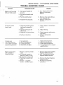
TROUBLE SHOOTING CHART
TROUBLE
Won't start, kicks back
and backfires.
l.
2.
3.
4.
5.
6.
No acceleration, low
top R.P .M., hard to
start.
l. Spark plugs improperly
2.
3.
4.
5.
6.
7.
Good spark but
engine runs on one
cylinder.
PROBABLE CAUSE
Spark plug wires reversed.
Flywheel key missing or
sheared.
Faulty condenser.
Improper timing.
Faulty breaker points.
Unhooked spark retarding
mechanism - or spring
broken.
gapped or dirty.
Magneto breaker points
improperly gapped or
dirty.
Faulty coil or condenser.
Loose or broken magneto
wires.
Blown head gasket.
Inlet lever adjustment
too low.
Crankcase leaking.
l. Leaking cylinder head.
2. Magneto wires broken
inside (coil ground
broken).
3. Cracked cylinder wall.
4. Defective spark plug.
REMEDY
l. Install wire correctly.
2. Replace key.
3.
4.
5.
6.
Replace condenser.
Re-time engine.
Adjust or replace points.
Reconnect mechanism or
replace spring.
l. Clean, adjust or install new
plugs.
2. Clean, adjust or install new
points.
3. Replace coil or condenser.
4. Repair or replace magneto
wires.
5. Replace head gasket.
6. Refer to
Carburetor Section.
7. Install new seal.
l. Check head for warps, cracks.
Install new gasket and
cylinder head.
2. Repair or replace wires.
()
3. Replace faulty cylinder.
4. Clean, adjust or install new
plug.
5. Breaker points improperly
5. Re-adjust points.
gapped.
No acceleration. Idles
well but dies down
when put to full
throttle.
6. Crankcase seal leaking.
6. Install new seal.
l. Low speed needle set too
l. to 7.
2.
3.
4.
5.
6.
7.
8.
lean.
Dirt behind needle and seat.
High speed jet obstructed.
Inlet lever set too low.
Choke partly closed.
Silencer obstructed.
Fuel pump not supplying
enough fuel due to:
(1) Punctured diaphragm
(2)Fiapper valves distorted.
Fuel line obstructed.
Adjust carburetor.
Refer to Carburetor
Section.
8. Remove fuel line. Clear
obstruction. Replace lin e .
9. Not enough oil in gas.
9. Refuel, using specified fuel/oil
mixture.
1-36
l 0 . Breaker points improperly
l 0. Adjust, clean or install new
gapped or dirty.
11. Engine improperly timed.
points.
11. Re-time engine to specifications.
(
SERVICE MANUAL · 197 5 SCORPION SUPER STINGER
TROUBLE SHOOTING CHART
(
TROUBLE
Engine runs by using
choke at high speed.
REMEDY
PROBABLE CAUSE
1. High speed needle set
1. & 2. Adjust carburetor.
Refer to Carburetor
Section.
too lean.
2. Dirt behind needle and
seat.
3. Fue l line obstructed.
3. Remove li ne, clear obstruc-
4. Inoperative fuel pump.
4. Refer to Carburetor
tion, replace line.
Section.
No power under
heavy load.
1. Magneto breaker points
improperly gapped or
dirty.
2. Ignition timing too far
advanced.
3. Magneto coil plate loose.
1. Clean, adjust or instal l new
points.
2. Ad just timing.
3 . Check magneto and secure
4. Faulty carburetion.
4.
Cranks over
extremely easy on
one or both cylinders.
Loss of compression.
1.
2.
3.
4.
1.
2.
3.
4.
Engine won't crank
over. Unable to
rotate flywh ee l.
1. Pi ston rusted to cylinder
2.
3.
4.
5.
Scored piston.
Blown head gasket.
Loose spark plug.
Head bolts not tight.
wa l l.
Crankshaft seized to
b e aring . (main or rod)
Broken connecting rod.
Flywheel se ized to _coil
plate.
Engine ..;. properly
asse m ~ ed after repair.
coil p late .
Refer to Carburetor
Section.
Replace faulty piston .
Replace head gaske t.
Check plug for security.
Torque head bo lts to proper
specifications.
1. Remove piston and cy l inder.
Replace defective parts .
2. &3. Disassemble engine.
Replace defective parts .
4. Remove flywheel. Replace
defective parts.
5 . Recheck re-assembly
procedure.
C)
l-37
SERVICE MANUAL- 1975 SCORPION SUPER STINGER
The following are possible causes of piston failures on Rockwell-5 and -8 engines.
The -5 is a 1973 version.
The -8 is the 197 4 and 1975 version.
1. Insufficient "break-in period" before full throttle application.
2. High speed needle adjusted too lean, especially on -8 400 engines.
3. Baffle foam caught in carburetor flange causing air leak.
4. Leaking air silencer boots on early production models.
5. Pick up in fu e l tank too long.
6. Loose carburetor on intake manifold causing air leak.
7. Leaking crankcase halves.
8. Leaking crankcase sea ls.
9. Leaking impul se fitting or plug.
10. Intake manifold spacers cracked causing air leak. (-8 engine)
11. Intake manifold misaligned. (-5 engine)
12. Leaking cy lind er head gaskets.
13. Screen in 1973 -5 engine carburetors not removed.
14. Leaking primer pumps.
15. Drive clutch weight bushings ticking causing over revving of engine.
16. Substandard fuel.
17. Excessive compression.
1-38
)
)
1975
Scorpion
Super
Stinger
Service Manual
Carburetor
Section
)
SERVICE MANUAL · 1975 SCORPION SUPER STINGER
Functional Description:
)
GeneralThe purposes of the carburetor are ( 1) to provide the amount of fuel that the engine needs in
operation and (2) to properly mix the fuel with air so that it will vaporize.
Pulsations from the crankcase through the impulse tube, actuates the carburetor fuel pump
diaphragm to move the fuel into the carburetor from the fuel lines. An increased engine fuel
demand causes a reduced pressure at the metering diaphragm which opens the needle valve.
More fuel enters through the needle valve into the carburetor bore where it is mixed with incoming air.
The four operational phases of the Walbro Carburetor used on the 1975 Super Stinger are :
(1)
(2)
(3)
(4)
Starting (choke) operation
Idle operation
Part-throttle operation
Full-throttle operation
0
Detailed performance of the carburetor in each of the four phases is described below. Figures
2-1 through 2-4 are schematic diagrams and as such are accurate, functional representations
of the carburetor, but in some features deviate from actual physical appearance.
Q
2-2
SERVICE MANUAL- 1975 SCORPION SUPER STINGER
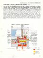
STARTING (CHOKE) OPERATION (See Fig. 2-1)
Fuel from the supply tank is drawn in the fuel inlet (1) into the surge chamber (2) through
the filter screen (3) by pulsations of the fuel pump diaphragm (4). The engine crankcase
pulsation transmitted through the external impulse fitting (9) or internal impulse hole (9A)
actuates the fuel pump diaphragm (4) which supplies pumping action for the fuel pump. The
fuel is drawn from the surge chamber through the check valve (5) and the channel (6). The
fuel continues past the fuel pump outlet check valve (7) and into channel (8). Fuel continues
through fuel channel (8) and to the needle valve (28). The metering lever spring (29) transmits a force through the metering lever (30) and seats the inlet needle valve (28) against
pressure. The metering diaphragm (1 O) is pulled upward by engine suction which is tran smitted through the idle discharge port idle hole (14) secondary idle holes (16) and part
throttle feed holes (17). The diaphragm action depresses the metering lever (30) ·and unseats
the needle valve (28) and allows the fuel to enter the metering diaphragm chamber (31) and
pass through the idle take off (11 ). Check valve (32) is forced open passing fuel into the main
nozzle (21) which also feeds the part throttle holes (17). Fuel only is fed through all discharge
holes.
FIG. 2-1
(
STARTING
(CHOKE)
OPERATION
\
Power needle
Choke valve
"closed"
--+- - - - - + /
Filter screen
Vapor return line fitting _
_
Inlet fitting (1)
l
Vapmr retum1
~ !fuel
(3)
COLOR CODE
Fuel
inlint
(
....
.•..
•··.
Air
Crankcase
Impulse Air
Fuel
I Vapor
2-3
SERVICE MANUA L - 1975 SCORPION SUPER STINGER
IDLE O PERATION
(See Fig. 2-2)
At idle speed the fuel passes from the id le take off ( 1 1) to the
idle pocket (13) where it mixes wi t h air from the secondary idle
holes (16). ~ This rich mixt ure passes around id le needle ( 12)
through the idle discharge port (14) where it mixes with additional air passing the throttle valve (19) a t poin t (15) .
I
FIG. 2-2
IDLE OPERAT ION
Power needle
(
open valve
Choke
--rt=~=~~==:J
u----t--'¥1.~::___+----- Main fuel nozzle
Part throttle holes
:_ •....Sec:onclary idle holes ( 16)
~~~---·---,;,.-;-~===~
Point (15)
Idle discharge port (14)
i~i~~iiiS~~Q~E~
Idle needle (12)
Idle pocket (13)
Idle take off (11)
Secondary
fuel p~mp
Inlet fitting
COLOR CODE
~
Vapor return
1Fuel
inlet
Fuel
Air
Crankcase
Impu lse A ir
:;:: Fuel
· ~ ·.
'2-4
I Vapor
SERVICE MANUAL· 1975 SCORPION SUPER STINGER
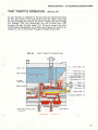
PART THROTTLE OPERATION
(See Fig. 2-3)
At part throttle, in addition to the fuel fed into the thrott le bore
by the id le system, more fuel enters past the check valve (32)
through passage (26) around t he power needle (22) and through
the passage (18) and discharged into the thrott le bo r e (20)
through the part throttle holes (17). All ports except the main
nozzle feed progressively as thrott le valve opens for smooth acceleration. Air is intermixed through air b leed nozz le (25).
FIG. 2-3
PAR T THROTTLE OPERATION
(22)
Venturi
(23)
Choke valve
- - Throttle valve
(19)
Main nozzle
Throttle bore
Part throttle holes
(21)
(20)
(17)
(16)
(14)
Air bleed
nozzle (25)
Passage
(18)
Needle valve
Idle needle
Passage
(12)
(26)
Check valve
(32)
Impulse fitting
(9)
Fuel pump diaphragm
(4)
Vapor return line fitting
to fuel tank
l ~apo
return
1
Fue i:nJet
2-5
SERVICE MANUAL· 1975 SCORPIO N SUPER STINGER
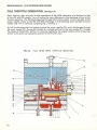
FULL THROTTLE OPERATION
(See Fig. 2-4)
Note: St arting, idle, and part throttle operati ons of the WDA carburetor are identical to that
of the WD and WR models. You wi ll notice the main difference is the discharge of fuel at fu ll
throttle operation . The WR discharges fuel through #(21) main nozzle, at only the base of th e
power needle, where as the WD and WDA discharge at five discharge ports para!!e! to power
needle (22). This is noted by comparing Fig. 1 and Fig. 4.
A t full throttle operation fuel passes around the power need le (22) and is discharged through
th e main nozzle (2 1) . During ful l throttle air is mixed with f uel in the main nozzle (21 ) through
the nozzle air b leed (25). Suction (or vacuum) created by the engine's piston action draws fuel
and air as the ports a r e exposed by position of the throttle valve.
FIG. 2-4
FULL
(WI DE OPEN)
THROTTLE OPERATION
19
24
21
23
26
27
28
29
30
31
32
33
4A
34
35
36
37
2-6
18
17
16
15
14
13
12
11
9A
10
9
SERVICE MANUAL. 1975 SCORPION SUPER STINGER
( _)
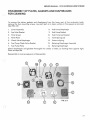
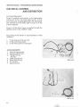
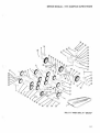
DISASSEMBLY OF PLATES, GASKETS AND DIAPHRAGMS
FOR CLEANING
To remove the plates, gaskets and diaphragms from the lower part of the carburetor body,
remove the four mounting screws. Lay each part on a clean surface in t h e sequence removed.
(See FIG. 2-5)
1.
Cover Assembly
8.
Fuel Pump Diaphragm
2.
Fuel Inlet Gasket
9.
Fue l Pump Gasket
3.
Filter Screen
10.
Fuel Pump Leaf Gasket
4.
Filter Plate
1 1.
Valve Springs (3)
5.
Check Valve Diaphragm
12.
Pressure Spring
6.
Fuel Pump Check Valve Gasket
13.
Metering Diaphragm Assemb ly
7.
Fuel Pump Plate
14.
Metering Diaphragm
Check diaphragms and gaskets thoroughly for cracks or leaks, by ho lding them against l ight .
Clean as required.
Reassemble in reverse sequence of disassembly.
()
12
FIG. 2-5
()
2-7
SERVICE MANUAL- 1975 SCORPION SUPER STINGER
MAIN CARBURETOR BODY DISASSEMBLY IN
CONJUNCTION WITH INLET NEEDLE VALVE
1.
Remove the four screws holding the
plates to the main body and disassemble
in one mass.
2.
Remove metering lever pin screw. (FIG.
2-6)
3.
Remove metering lever. Watch
spring does not fly out . (FIG. 2-6)
4.
Remove spring and Inlet Needle Valve.
5.
Clean or replace as required.
that
FIG. 2-6
MAIN CARBURETOR BODY DISASSEMBLY IN
CONJUNCTION WITH FINAL CHECK VALVES
AND DIAPHRAGMS.
1.
It is not necessary to remove
Inlet Needle Valve assembly,
but it may be easier to work in
this area without them. (See
Procedure Above).
2.
Remove three circuit plate
screws. (FIG. 2-6)
3.
Remove circuit plate, check
valve diaphragm and gasket.
(FIG. 2-7)
4.
Inspect check valve diaphragm.
5.
Remove Low and High speed
needles, if necessary, for
cleaning, grooves, channels,
etc.
METERING
LEVER
CIRCUIT PLATE
NOTE - DO NOT REMOVE SCREEN
UNDER HIGH SPEED NEEDLE. CARBURETOR WILL NOT FUNCTION
WITH SCREEN REMOVED. (See FIG.
2-7)
CHECK VALVE
DIAPHRAGM & GASKET
2-8
MET-ERING
LEVER
SPRING
FIG. 2-7
(
)
c
SERVICE MANUAL- 1975 SCORPION SUPER STINGER
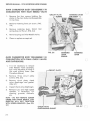
LOW SPEED ADJUSTMENT 400 &
440 SUPER STINGER
LOW SPEED ADJUSTMENT
290
AND
340
SUPER
STINGER.
On 400 and 440 Super Stingers, equipped with
throttle cracker carburetor, use the following
sequence for low speed adjustment.
290 and 340 engines do not have a
"throttle cracker" carburetor.
1.
Make sure throttle cracker screw is secured
tightly in choke shaft.
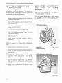
For low speed adjustments, follow Steps
9 through 12 of "LOW SPEED ADJUSTMENT 400 and 440 SUPER STINGER".
2.
Back off idle speed screw so it does not con tact throttl e arm.
3.
Turn idle speed screw in until contact is just
made with throttle arm.
4.
Turn idl e speed screw in one full turn.
5.
Turn Low Speed Mixture screw on until
needle seats lightly.
6.
Back off one turn.
7.
Close choke and
necessary).
start engine
(prime
)
IDLE SPEED SCREW
if
Engine will run with choke closed . Do not use
throttle in starting or engine will immediately
flood.
8.
Open choke and let engine warm up.
9.
Turn idl e mixture screw in to reach maximum
R.P.M. on Tach. Continue turning until R.P.M.
start to drop.
10. Screw idle mixture screw out to reach
maximum R.P.M. Continue out unti l R.P.M .
drop.
THROTTLE
CRACKER SCREW
FIG. 2-10
LOW SPEED MIXTURE SCREW
11. Set idle mixture screw half w ay between
drop points. This is th e correct idle mixture
setting.
12. Adjust idle speed screw
R.P.M.
to obtain 2,200
)
FIG. 2-11
2-10
SERVICE MANUAL · 1975 SCORPION SUPER STINGER
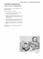
CARBURETOR PRESSURE TEST
(
(WRA and WDA CARBURETORS)
The pressure test i s used to determine if the
needle valve leaks.
The test procedure is as follows:
1.
Disconnect the fuel line from the fuel inlet connector on the carburetor.
2.
Connect the leak detector (Scorpion P/N
907000) pressure li ne to the carburetor fuel
inlet connector.
3.
Remove the carburetor vapor return line and
hold your finger over the carburetor fitting.
4.
Pressurize the carburetor with the leak
detector plunger pump. Do not exceed 12
PSI.
The needle valve, properly seated, should hold a
constant 8 psi.
Fig. 2-12
2-I I
SERVICE MANUAL- 1975 SCORPION SUPER STINGER
)
(
r)
2-12
SERVICE MANUAL· 1975 SCORPION SUPER STINGER
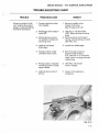
TROUBLE SHOOTING CHART
(_;
TROUBLE
Excessive carbon buildup in engine & on spark
plugs or eng ine flooding.
(Fuel Rich Condition)
PROBABLE CAUSE
l. Foreign obstacle under
inlet needle.
2. Diaphragm lever adjustment OFF.
REMEDY
l. Remove needle valve.
Inspect and clean .
(See Procedure P 2-8)
3. M etering lever spring
not seated in dimple on
metering lever.
2. (See Fig. 2- 13) Should be
.020" above surface of valve
body.
3. Remove plates and inspect
spring. Locate spring correctly
(See FIG. 2-6)
4. Leaking fuel pump
4. Install new diaphragm.
diaphragm.
()
5. Foreign matter under
umbrella check valve.
5. Blow through screen on
opposite side of Plate
#13. (See FIG. 2-5) Umbrella
check va lve is orange colored
rubber p lug.
6. Wrong angle, or abused
metering portion of high
speed needle. ·
6. (See FIG. 2-9) Install
correct needle.
7. Leaking check valve in
7 . In spect and replace as
primer.
(
---
necessary.
I
FIG. 2-13
2-13
SERVICE MANUAL - 197 5 SCORPION SUPER STINGER
TROUBLE SHOOTING CHART
TROUBLE
Engine runs hot, spark
plugs burn. (Fue l lean
condition)
r .
!
I
PROBABLE CAUSE
1. Dirt in fuel channels.
1. Disassemble, wa sh and blow
clean .
2. Metering lever adjustment incorrect.
2. (See FIG. 2- 13) Should be
.020'' above surface of valve
body as shown.
3. Leaky nozzle check valve
diaphragm.
3. Replace diaphragm.
4. Hole in metering
diaphragm.
4. Replace diaphragm.
5. Impulse line leaking
or pinched.
5. Replace as necessary.
6. Intake manifold gasket
leaking.
6 . Replace as necessary.
7. Leaking insulation plate
between carburetor and
manifold.
7. Replace as necessary.
8. Leaking diaphragm check
valve.
2-14
REMEDY
8. Replace diaphragm check
valve assembly. (See procedure P 2-8)
9. Fuel pump d iaphragm
check valve worn.
9. Replace fuel pump diaphragm .
10. Fuel inlet screen dirty.
10. Remove bottom plate and
clean screen.
11. Restrictions of fuel
from main supply.
11 . Check complete system
from fuel pick-up in tank
to carburetor making sure
fuel pick-up is staying in
fuel and tank is vented
sufficiently.
12. Air intake silencer leaks.
12. Repair or rep lace as required. Insure that metal.
clamps hold the rubber
bellows securely to the
upper and lower sections of
the silencer.
13. Damaged diaphragms
(From incorrect deicing).
13. Replace as necessary. Use
de-icers developed specifically for use with
diaphragm carburetors.
Do not use regular automobile de-icers.
( )
u
)
1975
Scorpion
Super
Stinger
Service Manual
.
Electrical
Section
I
3-1
SERVICE MANUAL· 1975 SCORPION SUPER STINGER
ELECTRICAL SYSTEM
The Scorpion Super Stinger Snowmobile Electrical System is
divided into four ( 4) subdivisions:
A.
B.
C.
D.
LIGHTING COILS
Power Generation
Ignition
Voltage Regulation
Electrical Control and
Distribution
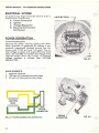
POWER GENERATION
Functional Description :
Electrical AC power, used for lighting and tacho meter operation is generated by rotating a permanently magnetized flywheel around two stationary coi Is ( 1- 120 watt and 1-23 watt). The noload voltage increases with engine RPM and could
reach 32 volts RMS. To maintain the voltage at the
required system level {13-14 volts), on external
voltage regulator is utilized . {See VOLTAGE
REGULATION)
ad
FIG. 3·2
MAIN ELEMENTS:
1.
2.
3.
Magnetic Flywheel
120 watt coil (mounted on stator plate)
23 watt coil (mounted on stator plate)
:,(/ / 7 / / /7 / / /7 7 / / // 7 ij
'/
~
~//
~
FIG. 3-1 POWER GENERATION SCHEMA TIC
3-2
ENGINE
CONNECTOR
FIG. 3·3
SERVICE MANUAL· 1975 SCORPION SUPER STINGER
c)
IGNITION
Functional Description:
(See SCHEMATIC FIG. 3-8)
Rockwell engines are equipped with a flywheel
magneto type ignition. An electrical current is
generated by rotating a permanently magnetized
flywheel about the ignition coil. The current
initiated in this coil in turn energizes the primary
coils of the external ignition coils. The secondary
coils of the external ignition coils ore situated in
the force field generated by the primary coils.
When the points close, causing an interruption of
the current flow through the primary winding, its
force field immediately collapses and generates a
very high voltage in the second coil. This voltage in the
region of several thousand volts will jump the spark
plug gap causing ignition to begin.
r---ENGINE
CONNECTOR
The collapsing lines of force cut through the primary
windings, raising the voltage in that circuit also.
As this occurs, the condenser absorbs the generated current to reduce the tendency to overload
the points. As soon as the voltage level in the
primary winding drops below that of the condenser,
current again flows in the original direction,
energizing the system. This occurrence and the reversal happens severa l times each cycle creating a
powerful, long duration spark for more reliable
ignition. ~
FIG. 3-5
MAIN ElEMENTS:
1.
2.
3.
4.
5.
Ignition Coil (Stator)
Condensers (2)
Breaker Points (2)
Ignition Coils (External) (2)
Spark Plugs (2)
FIG. 3-6
3-3
SERVICE MANUAL· 1975 SCORPION SUPER STINGER
{STATOR)
SEE ENGINE DISASSEMBLY
(SECTION 1) FOR FLYWHEEL
AND STATOR REMOVAL
FIG. 3-7
CONDENSER
Ht·
~SPARK
PLUG
EXTERNAL IGNITION COILS
~SPARK PLUG
-FIG. 3-SIGNITION SCHEMATIC
ENGINE CONNECTOR
3-4
SERVICE MANUAL- 1975 SCORPION SUPER STINGER
(
()
--STATOR IGNITION COIL TO
EXTERNAL COIL CONNECTORS
FIG. 3-9
Ex;TERNAL COIL
'
COIL TO SPARK PLUG LEAD
EXTERNAL COIL
GROUND
FIG. 3-10
3-5
SERVICE MANUAL- 1975 SCORPION SUPER STINGER
VOLTAGE REGULATION
Functional Description:
The voltage regulator is connected across the
lighting coils in parallel with the electrica l load
of the sled. (See SCHEMATIC - ELECTRICAL DISTRIBUTION AND CONTROL- FIG 3-17). Under operating
condi tion s, the vo ltage drop across the regulator is
such that approxi'llately 13.8 V RMS is supplied to
the snowmobile lighting circuit. Two types of
regulators are described in this section.
NORMAL LIGHTING COIL VOLTAGE
ALTERATION OF VOLT AGE
WAVE WHEN SCR
CONDUCTS
Scorpion P/N 0427 48 - (See FIGs. 3-11, 3-12 and
3-13).
MAIN ELEMENTS:
1.
2.
3.
4.
5.
TIME
FIGURE 3-11
Trimmed Resistor
Light Bulb
Photo Electric Cell
Diac (Trigger)
Silicon Control Rectifier
(Thermatab)
(
\
The intensity of the light output of the light bulb
directly indicates the RMS Voltage level. When the
intensity exceeds a speci fic level, a sequence of
events occurs.
a.
b.
c.
d.
The light is sensed by the photo cell,
A signa l from the photo cel l actuates the diac.
The diac triggers the SCR.
The SCR conducts, in effect short circuiting the
lighting coi l for part of the cycle. (See FIG.
3-11)
VOLTAGE REGULATOR P/N 0427 48, 043299
FIG. 3-12
This action regulates the RMS Voltage to the
lighting circuit at the required level.
TRIMMED
RESISTOR
THERMATAB
(SCR)
LIGHT
BULB
/.
REGULATOR
CONNECTOR
3-6
FIG: 3-13
VOLT AGE REGULATOR SCHEMA TIC
PIN 042748
SERVICE MANUAL- 1975 SCORPION SUPER STINGER
Scorpion PIN 043299
(See FIGs. 3-11, 3-12 and 3-14}
MAIN ELEMENTS :
l.
2.
3.
4.
5.
Silicon Control Rectifier (SCR)
Resistors (R 1, R2, R3, R4, Trim)
Condenser (C 1)
Diodes (CR1, CR2, CR3, CR4)
Transistors (Z1, Q1)
0::
u
VI
This solid state regu-lator is also a shunt type regula tor. When the magneto output drops below the
specified pre-set regulator voltage level , the regulator drops out of the system, providing maximum
availab le vo ltage to the load at decreased speeds.
In the first half of the operating cycle when line 1 is
positive with respect to line 2, C1 wi ll charge
through CR1, C1, R2 and CR2 until the voltage drop
across C 1 reaches the level necessary to cause Z 1
to conduct. At this point, Q1 will draw base current
and then pass current through CR 1, the emitter collector of Q 1 and into the gate of SCR. SCR is "turned
on" and shunts the output of the magneto.
u
In the second half cycle the shunting mechanism of
the regulator is not operative.
If there i_s a sufficiently heavy load on the magneto
during the first ha lf cycle, the load effective ly holds
the vo ltage output to a va l ue less than that required
to turn the SCR on and therefore fu ll output goes to
the load.
"~" 1
wz~
r2 ~
N'
U
w
~ :-....
z
1,.." -.........................~~-......~~~ ~z
--------------------------~ ...~
..
c(
::J
()
w
ar:
FIG 3- 14 MAGNETO VOLTAGE REGULATOR
{SOLID STATE)
(
PI N 043299
3-7
SERVICE MANUAL· 1975 SCORPION SUPER STINGER
ELECTRICAL CONTROL
AND DISTRIBUTION
Functional Description
Power is supplied continuously to the tachometer
mechanism and to the brake light switch, so that
any time power is being generated, the tachometer
will indicate and the brake light will go on if the
brake is applied.
Power to all the other items is supplied through the
ignition switch in the "LIGHTS" mode.
Grounding of the System is accomplished at three
locations:
1.
2.
3.
To the chassis at the rear end
To the instrument panel
To the stator plate on the engine
MAIN ELEMENTS:
1.
2.
3.
4.
5.
6.
7.
n
Main Wiring Harness
Seat Wiring Harness
Taillight Wiring
Harness
Safety Stop Switch
Break Light Switch
Hi-Lo Switch
Ignition Switch
FIG. 3-15
, TAlL !.UiHT
It A~ t.u;;s$.
>;EAT
0 li/\R'JE5'>
FIG. 3-16
3-8
I
I
SAFETY
STOP
SWITCH
TACHOMETER
MOVEMENT
I ~£
I
IGNITION
COIL
LIGHTS
I
Ill
LIGHT
SWITCH
TACHOMETER &
SPEEDOMETER
1.-.
•
::::1:
m
I
)>
-
c
,..
c;
::::1:
-1
(I)
m
;a
sn
m
3:
•
/
/
/
/
TAILLIGHTS
BRAKE LIGHT
I
w
.:0
-o
......
U'l
(I)
n
0
;a
"'U
0
(I)
/
D
I
z
/
·VOLTAGE
REGULATOR
HI-LO
SWITCH
>
z
>
,...
c:
c:
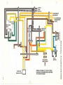
WIRING SCHEMATIC (COLOR CODED)
ELECTRICAL DISTRIBUTION & CONTROL
1975 SUPER STINGER
"'U
m
;a
(I)
::!
z
C)
m
;a
SERVICE MANUAL· 1975 SCORPION SUPER STINGER
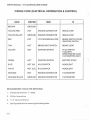
WIRING CODE (ELECTRICAL DISTRIBUTION & CONTROL)
j
COLOR
FUNCTION
FROM
TO
BROWN
GROUND
YELLOW/RED
HOT
ENGINE CONNECTOR
REGULATOR
YELLOW /BLACK
GROUND
ENGINE CONNECTOR
REGULATOR
RED
HOT
VOLTAGE REGULATOR
BRAKE SWITCH CONN.
IGNITION SWITCH
TAN
HOT
BRAKE LIGHT SWITCH
BRAKE LIGHT
YELLOW
HOT
IGNITION SWITCH
HI-LO SWITCH
TAILLIGHT
SPEEDOMETER LIGHT
TACHOMETER LIGHT
GREEN
HOT
IGNITION SWITCH
ELECTRIC START
BLUE
HOT (HI)
HI-LO SWITCH
HEADLIGHT
WHITE
HOT (LO)
HI-LO ·SWITCH
HEADliGHT
ORANGE
HOT
ENGINE CONNECTOR
TACHOMETER
ORANGE/BLACK
GROUND
ENGINE CONNECTOR
TACHOMETER
'
()
RECOMMENDED TOOLS FOR SERVICING:
1.
Standard Screwdriver, 1/4" blade
2.
Phillip's Screwdriver
3.
7 /16" open-end Wrench
4.
See Engine Section for removing & installing stator
(
3-10
SERVICE MANUAL· 1975 SCORPION SUPER STINGER
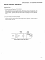
. SPECIAL TESTING • ELECTRICAL
(
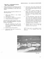
Regulator Tests
1. Resistance pcross Regulator (P /N 0427 48)
Hook ohmmeter across regulator leads. Resistance shou ld read between 100
and 1000 ohms. If resistance is less than 100 , the SCR is shorted. If the resistance
is above 1000 , generally the lamp has burned out opening the circuit (See FIG.
3-12).
2. Set point check (PIN 042748, 043299)
Use test circuit as shown below. Read voltage across regulator. Value shou ld be
approximately 13.8 volts.
(
lOOW
s..n...
OPEN
• TEST
'----.-----4-
120V
REGULATOR SET POINT TEST CIRCUIT
•
(
3-11
SERVICE MANUAL- 1975 SCORPION SUPER STINGER
TROUBLE SHOOTING (ELECTRICAL)
)
TROUBLE
No lights
PROBABLE CAUSE
REMEDY
Open Circuit:
Faulty Switch(s)
Separated Connector(s)
Cut Wiring
Repair or replace faulty
or damaged element.
Wiring shorted to ground:
Damaged Insulation
Repair or replace damaged
or faulty element.
Faulty Regulator (Shorted SCR)
Replace regulator.
Shorted or open lighting coil.
Replace armature plate.
Faulty regulator - Incorrect
regulator set point (too low).
Replace regulator.
Faulty regulator- burned out
regulator light bulb. Incorrect Set
Point (too high).
Replace regulator and failed
bulbs .
Burned out
lights (individual)
Failed bulb.
Replace bulb.
Burned out lights
Intermittent short in wire harness.
Repair or replace wire harness.
Engine won't run
1. Open or shorted windings in
1. Replace armature plate.
.weak or no
spark
ignition coils (stator) .
2. Open or shorted windings.
in external ignition coil.
3. Shorted condenser- dirty or
worn.
4. Damaged (burned) points.
4. Replace points.
1. Burned or fouled plugs.
1. Replace plugs. Determine that
Dim lights
Burned out
lights (all)
Engine won't runAdequate spark.
()
2. Replace external coil.
3. Replace condenser.
correct plugs are being used.
CHECK ENG INE TROUBLE
SHOOTING.
2. See Engine Trouble Shooting
Section
Unacceptable
Engine Performance
See Engine Trouble Shooting
Section
!
3-12
('
1975
Scorpion
Super
Stinger
Service Manual
Clutch/Drive
Section
4- J
SERVICE MANUAL· 1975 SCORPION SUPER STINGER
DRIVE SYSTEM
Functional Description:
The main elements included in this system are:
1. Drive Clutch
2. Drive Belt
3. Driven Clutch
4. Chain Case with sprockets, chain and chain tensioners.
5. Drive shaft with track drive sprockets.
The power from the engine is transmitted through this system to the track in
sequence of elements listed above to propel the machine.
The drive clutch, belt and driven clutch serve as a torque converter. The torque
converter on the snowmobile "down shifts" to a lower ratio as the track load increases as readily as it "up shifts" when the track load decreases.
To accomplish the automatic shifting, the movable sheave of the driven clutch
is fitted with a helical ramp which is guided by a follower. This sheave is controlled by a spring pre-stressed in torsion and compression to hold the sheaves
together at the maximum pitch diameter.
n
Under acceleration, the torque from the engine is greater than the demand
from the track. The drive clutch then closes, forcing the belt outward between
the sheaves. Belt tension and wedging action .is unbalanced at the driven clutch
and the sheave faces are wedged open against the helical cam. This action
winds up and compresses the spring.
Under steady running, all forces are balanced and the belt chooses a ratio at
which this ~ balance exists.
Under deceleration, the driven sheave is stalled slightly, which unbalances the
forces so that the sheave is forced to a new larger pitch diameter. Belt tension
is thus increased, the wedging action opens drive sheave and a new lower
pitch diameter is chosen to again bring all forces to balance.
)
4-2
SERVICE MANUAL· 1975 SCORPION SUPER STINGER
DRIVE CLUTCH DISASSEMBLY
()
1. Remove engine cover, disconnecting choke &
primer.
Remove clutch guard. (See Figure 4-1)
FIG 4·1
2. Remove clutch attaching bolt and bell
retaining bolt. Use impact wrench capab le of
75 or more ft. lbs. torque (In the field alternate method may be used.) Making sure
ignition is off, run engine up on compression
using %" socket and ratchet. Strike ratchet
with plastic or rubber mallet. (See Figure
4-2.)
FIG 4·2
3. Remove bell housing (See Figure 4-3 .)
FIG. 4·3
4-3
SERVICE MANUAL· 1975 SCORPION SUPER STINGER
4
Movable sheave should slide off spline
easily. Next remove spring and retainer.
(See Figure 4 -4.)
u
FIG 4-4
5. Remove snap ring retainer and idler bearing
if necessary. (See Figures 4-5 and 4-6 .}
)
FIG. 4-5
)
FIG. 4-6
4-4
SERVICE M ANUAL • 1975 SCORPION SUPER STINGER
c
6. If necessary to remove stationary sheave, insert plug (2 13/16" long x 3/4" diameter) in
stationary center hole and re-insert be ll
retainer bolt. Tightening bell bo lt will force
stationary off crankshaft. (See Figure 4-7.)
FIG. 4 -7
r
7. Removing torque plug retai ner will a l low
torque p lug to be removed and inspected.
(See Figure 4 -8.)
FIG. 4 -8
4-5
SERVICE MANUAL- 1975 SCORPION SUPER STINGER
)
8. Detaching springs and weight arm retainers
will allow weight arms to be removed. (See
Figures 4 -9, 4-10, 4-11.)
. .•!'
DRIVE CLUTCH INSPECTION
FIG. 4-9
ln~pect weight arm bushings and rollers for
cracks and flat spots. Also check snap rings on
weight arm shaft ends.
Inspect torque plug for fit and wear. (Should have
no more than .020" space between torque plug
and casting.)
Inspect idler bearing for freedom of rollers and
retention of lubricant.
FIG. 4-10
Inspect snap ring groove on stationary and spring
retainer for wear.
Inspect bell housing for cracks, particularly in
center area near spline.
FIG. 4-11
4-6
SERVICE MANUAL- 1975 SCORPION SUPER STINGER
RE-ASSEMBLY OF DRIVE CLUTCH
CAUTION:
If stationary has been removed,
assure that there is no grease on
either the shaft or sheave before reassembly.
n
Re-install idler bearing, snap ring, retainer and
spring. Place weight arms on movable sheave (after checking them for lubri cation) . Attach
retainers, checking to see that the small locating
hole in the bearing aligns with the detent on inner face of retainer. Install torque plug and
torque plug retainer. Install bell housing,
checking alignment with stub on torque plug
provided for this purpose. Place spring washer
and bell retainer bolt on next, assuring that the
bolt has bottomed out securely in proper alignment. Install clutch attaching bolt. Torque on both
bolts to 50 ft. lbs.
0
4-7
~ERVICE
MANUAL- 1975 SCORPION SUPER STINGER
DRIVEN CLUTCH DISASSEMBLY
j
1. Remove chciin case cover.
2. Remove chain tensioners, unbolt and remove
top sprocket and chain .
DRIVEN SHAFT
/LOCKING BOLT
;:;>'¥/)
()
TENSIONER
(
4-8
SERVICE MANUAL· 1975 SCORPION SUPER STINGER
(
3. Remove driven unit from chaincas e (tapping
shaft lightly with plastic mallet). Remove
snap ring and washer from cam top and slide
off shaft. (See Figures 4 - 13, 4 - 14, 4-15.)
CAM TOP
HELICAL RAMP
(
CAM BOTTOM
FIG. 4-13
(_)
FIG. 4-14
FIG.4-15
4-9
SERVICE MANUAL· 1975 SCORPION SUPER STINGER
4. Remove key and main spring. (See Figure 4 - '
16.)
;.
KEYWAY
KEY
FIG. 4-16
5. This should allow cam bottom and movable
sheave to be removed as a unit (See Figure
4-17.), and disassembled if necessary. (See
Figure 4-18.)
(}
FIG. 4-17
FIG. 4-18
4-10
SERVICE MANUAL· 1975 SCORPION SUPER STINGER
1
j
6. Stationary sheave m ay th en be unbolted
from clutch shaft (See Figures 4-19 and
4-19A) and bearings can 'oe pressed off
if necessary .
STATIONARY SHEAVE
CLUTCH SHAFT
FIG. 4-19
()
FIG. 4-19 A
4-11
SERVICE MANUAL· 1975 SCORPION SUPER STINGER
DRIVEN CLUTCH INSPECTION
Inspect snap ring groove for wear.
Inspect Helical ramps for wear and breakage.
(See Fig. 4-13)
Inspect bronze bushing in cam bottom for any
signs of looseness or slippage (should be staked
in solidly).
Rotate and check bearings visually.
In spect sheaves for cracks particularly around
bolt holes .
Check sp lines and threads on sprocket side of
main shaft for wear, crossthreading, etc.
'RE-ASSEMBLY OF DRIVEN CLUTCH
Attach stationary sheave to clutch shaft. Assem ble cam bottom and movable, then place on shaft
followed by th e woodruff key and main spring.
Place cam top on shaft, preloading spring 1j3 turn
and install washer and snap ring.
Upon replacing the driven clutch in chaincase,
check to assure that the 0-ring in chaincase bore
is intact and in good condition. Also check 0 -ring
in chaincase cover before installation.
r
4- 12
SERVICE MANUAL· 1975 SCORPION SUPER STINGER
DRIVE BELT SPECIFICATIONS
(
Drive belt width
Drive belt outside diameter
inches.
1 1/8- 1 3/16 inches
43 1/8 - 43 1I 4
Clutch offset (Drive to Driven) 3/8 inch
Center to center distance 10 1/2 inches
(Drive clutch to Driven clutch)
(
CLUTCH ALIGNMENT
BAR-- - - - (For 3/8" Offset)
4-13
I
SERVICE MANUAL- 1975 SCORPION SUPER STINGER
CHAIN CASE DISASSEMBLY
)
Remove cover, tensioners, upper and lower bolts .
Remove sprockets with chain. Remove bearing
flange bolts and brake cable. Taking care to
check . number of shims between the chaincase
and the tunnel :. and their specific locations,
remove the chaincase from the tunnel. When the
chaincase is reassembled to tunnel, assure that
the spacers go back where they were. Reverse
procedure to install.
REMOVAL OF FRONT DRIVE SHAFT
Remove chaincase cover, tensioners, lower
sprocket and chain. Loosen locking collars on
front drive bearings (see Fig. 4-21). Remove
speedometer, drive adaptor and flanges. Slide
drive shaft through chaincase mounting hole until
right side clears main frame and remove. (It
is necessary to detach forward end of pararail to gain clearance for entire removal of front
drive shaft- See Suspension Section.)
()
REMOVAL OF FRONT DRIVE SPROCKET Punch out spiral pins (see Fig. 4 -21, 4-22). Then
taking care to see that the shaft is clean, slide
sprockets off. To reassemble, reverse procedure.
LOCKING COLLARS
SPIROL PINS
4-14
FIG. 4-21
SERVICE M A NUAL · 197 5 SCORPION SUPER STINGER
c
SPIROL PIN
FIG. 4-22
BRG. FLANGES
Inspection of Drive Shaft
0 -RING
FIG. 4-23
Observe shaft for signs of stress, cracks and bending, check bearings and co l lars for breakage.
Check sprockets for loosening of pin holes.
NOTE: Small cracks in the white material of the
drive sprocket are not signs of failure, but a result
of shrinkage during manufacture.
4-15
SERVICE MANUAL· 1975 SCORPION SUPER STINGER
TROUBLE SHOOTING
)
The operating diameter of the drive and driven
clutch governs the ratio of reduction or advantage in the snowmobile drive train. Therefore,
to gain maximum performance and economy,
these areas cannot be overlooked.
The following are some symptoms, causes and
cures to aid in trouble shooting the clutch/
drive system.
Engine Overs peed:
Excessive
vibration of
drive train:
Excessive noise
from front drive
system:
4-16
REMEDY
CAUSE
TROUBLE
Drive clutch may not be closing fully. This can
be checked by drawing a line on the face of
the sheave (drive or driven) with a crayon
from the center outward. Then running the
machine at top speed will tell you how far
the clutch closed by erasure of the line by the
belt.
Disassemble clutches
examine and replace
malfunctioning parts.
If the clutch is closing fu l ly, the belt may be
wrong length or the center to center distance
of the clutches may be off. Finally, check the
number of teeth on upper and lower
sprockets.
Replace belt. Correct
center to center distance (see belt specs.)
Replace
incorrect
sprocket.
Tachometer
(high)
incorrectly
Replace tach.
Belt may be worn and too narrow to achieve
correct ratio (see belt specs).
Replace belt.
may
be
reading
Track may be too loose allowing sprockets to
slip over drive lugs or "ratchet".
Correct track tension.
Chain may
sprockets.
Check and
replace
broken
or
weak
chain tensioners.
be
slipping
over
teeth
on
Malfunction of front drive bearings.
Replace bearings.
Chain case may be dry of oil.
Disassemble
and
check - chain, sprockets and chain case
cover seal (0 ring) replace worn parts and
reassemble.
Refill
with oil check level
and check for leaks.
~
1
)
1975
Scorpion
Super
Stinger
Service Manual
Suspension
Section
n
5-l
SERVICE MANUAL - 1975 SCORPION SUPER STINGER
FUNCTIONAL DESCRIPTION:
The four main e lements of a snowmobile suspensio n are:
1.
2.
3.
4.
Skis
Track Suspension
Seat
Operator
All e lem ents work together to perform the sus pension functions to the optimum degree.
Th e su spens ions ore basically designed to:
1.
2.
3.
4.
Protect the operator from physical abuse or
injury.
Keep th e operator from being ejected from
his operating position and contro ls.
Prevent damage to the machine.
Increase ground contact and improve traction .
( )
On the 1975 Super Stinger, the track suspension
("Pa ra-Rail ® -Snowmobi le Suspension") is a unit
type suspens ion whi ch simp ly means that it is a
sing le unit working as a whole as opposed to th e
multiple unit, bogey type suspension . It also
possesses the advantage of being able to tra verse marginal snow conditions without damaging e ffect s to th e suspension system .
(
5-2
)
SERVICE MA NUAL • 1975 SCORPION SUPER STINGER
(
(
FIG. 5·1 "P ARA·RAIL ®" G ROUP
5-3
SERVICE MANUAL - 1975 SCORPION SUPER STINGER
SUSPENSION SYSTEM - REMOVAL, DISASSEMBLY, ASSEMBLY
)
For the removal, maintenance and installation of
the "Para-Rail ® - Snowmobile Suspension", we
will refer to the "Para-Rail" group for identification of component parts by the numbers l
through 57.
(A} REMOVAL
l.
Remove the two hex cap screws, #56 and
washers, #57.
2.
Raise and block rear of vehicle off the
ground.
()
NOTE:
In Figs. 5-3 through 5-6 the track has been
removed for clarity of illustration.
3.
FIG. 5-2
Remove the two nuts, #51, from the two eye
bolts, #11.
FIG. 5-3
5-4
)
SERVICE MANUAL'" 1975 SCORPION SUPER STINGER
4.
(
5.
Remove the two whiz lock screws, #20
securing the rear suspension plates to the
rear axle.
Release the track tension by loosening the
two screws, #46.
FIG. 5-4
(
6.
Remove hex screws, #S3 and nut, #5.4 , on the
two suspension plates. Remove plates.
FIG. 5-5
(
FIG. 5-6
5-5
SERVICE MANUAL- 1975 SCORPION SUPER STINGER
7.
Remove the two whiz lock screws, #20,
located on the side of the tunnel in front of
)
the footrests.
The para-rail can now be removed from the
track and tunnel.
(B) DISASSEMBLY- "PARA-RAIL ® -SNOWMOBILE
SUSPENSION"
1.
FIG. 5-7
Bracket- axle adjustment #42
Remove the four (4) hex screws, #21 and
lock nuts, #22.
FIG. 5-8
)
5-6
SERVICE MANUAL - 1975 SCORPION SUPER STINGER
2.
Springs #2- #4
Place su spension on the floor and in stall
spring release tool.
To r e lease th e springs from the spoo ls, #18,
th e rea r of "Para-Rail ® - Snowmobile
Su spens ion" mu st be h e ld down whil e downward pressure is applied with the right arm
and upward pressure with th e left arm.
FIG. 5-9
n
3.
Linkage Arm #30
Remove th e two screw s, #25, wa shers
#26 and #48 .
FIG. 5-10
Remove th e two button h ead sc r e w s,
#33 and spring retainers, #32.
(
)
0
l
FIG. 5-11
5-7
SERVICE MANUAL · 1975 SCORPION SUPER STINGER
4.
Bogey Wheel #29.
(
Remove shaft, #28, and this will allow the
bogey wheel #29, tube spacers, #8, tube
spacers, #49, bearing, #5, and remaining
washers, #48, to be free from suspension .
(Fig. 5- 12.)
FIG. 5-12
5.
Spools #18
Remove the two screws, #25, and washers,
#26, from the wheel shaft, #23. Push shaft
through rails, #6 and spools are removed.
(Fig. 5-13.)
6.
Rails #6
Remove the remaining eight (8) screws, #25,
and washers, #26. This will allow the rail s to
be removed from the remaining shafts,
bogey wheels, and tube spacers. The "ParaRail ® - Snowmobile Suspension" is completely disassembled at this time.
FIG. 5-13
(
FIG. 5-14
5-8
SERVICE MANUAL . 1975 SCORPIO N SUPER STINGER
(l
(C) ASSEMBLY
1.
Prior to assembly procedure, ensure that all
components are clean and al l defective parts
have been rep laced.
2.
Apply a coat of low temperature grease to al l
shafts prior to assembly. (Scorpion clutch
lube 906800 may be used.)
3.
Reverse procedure as outlined for disassembly.
NOTE: Ensure that all tube spacers and bogey
wheels are assembled in their respective areas
on the shafts.
0
Torque requirements for assembly are:
ITEMS
TORQUE
20
50-60 Ft-Lbs.
21
15-19 Ft-Lbs
22
15-19 Ft-Lbs
25
15-19 Ft-Lbs
53
15- 19 Ft-lbs
54
15-19 Ft-Lbs
()
I
5-9
I
SERVICE MANUAL · 1975 SCORPION SUPER STINGER
SPECIAL ADJUSTMENTS
"PARA-RAIL ® ·SNOWMOBILE SUSPENSION"
ADJUSTMENT
[J
The rear spring adjustment governs preload and
should be correlated with the weight of the rider
or riders normally using the machine.
Too much spring tension will result in a harsh ride
and increases the weight carried on the skis, thus
increasing steering effort.
Too little spring tension will result in the bottoming out of the suspension, a harsh ride and
shortened life to the suspension components will
occur.
1.
The proper spring tension may be obtained
by having the rider(s) sit on the machine, in
the normal sitting position and measure the
distance between the floor and the bottom of
the running board at the rear of th e machine
(either side). This mea surement mu st be
4 1/2" to 6".
2.
To adjust, loosen th e nuts on the eye bolts
and adjust accordingly, making certain that
each spring is tightened or loosened the
same amount.
3.
Repeat Step 1, and tighten the nuts on the
eye bolts securely when the 4 1/2" to 6"
measurement is attained.
()
NOTE: When 300 lbs. (combine d passenger
weight) is normally carried on machine, a "heavy
duty" spring kit should be installed on 111-:Jchine.
This kit is available at your Scorpion """.: i.;tributor
a s an accessory item.
f )
5-10
SERVICE MANUAL- 1975 SCORPION SUPER STINGER
"PARA-RAIL ® -SNOWMOBILE SUSPENSION": TRACK TENSION
(\
Proper track tension is extreme ly important
to assure long life of al l associated com ponents and efficiency of the track drive
system.
4.
Insert both "Track Jacks" between the
track and both bogey wh eels , located on
the third bogey axle, ahead of the rear
idler wheels.
5.
If the track is properly tensioned, the
green ring should be just visible or
aligned with the lip of the cy linder. Adjustment is required if the green ring is
not visible, or is above the lip of the
cylinder.
6.
To make adjustment, loosen the lock
nuts on the track adjustment bolts, as
well as the rear suspension mounting
screws (rear of tunnel ju st below seat),
and either tighten or loosen the adjustment bolts until proper adjustment is
measured on both "Track Jacks" (green
ring aligned with lip on cylinder).
7.
Retighten the lock nuts on the track adjustment bolts, as well as the rear
suspension mounting screws.
The track tension shou ld be checked at the
following intervals:
1.
2.
3.
When th e machine is new (d ea ler
preparation) .
After the first 10 hours.
Every 30 days, or 200 miles of operation.
4.
At the start of each snow season.
The following procedure app li es to all "ParaRail ® - Snowmobile Suspension" equipped
Scorpion snowmobiles:
n
(
1.
The track shou ld be at room temperature or shou ld have been recently
run to remove any stiffness, caused by
cold weather.
2.
Elevate the rear of the machine.
3.
Adjust each "Track Jack" to one and one
quarter inch ( 1 V4).
NOTE: Track Jacks" are available at Scorpion, Inc. It is an accessory item, Part
#901736.
FIG. 5-16
5-ll
SERVICE MANUAL· 1975 SCORPION SUPER STINGER
IN THE EVENT "Track Jacks" are not available, the
following procedure may be employed to achieve
track tension:
1.
The track shou ld be at room temperature or
should have been recent ly run to remove any
stiffness, caused by cold weather.
2.
Elevate th e rear of the machine.
3.
Apply ten ( 10) lbs. of force or weight evenly
distributed across the track under both
bogey wheels, located on the third bogey
axle, ahead of the rear idler wheels.
4.
To make adjustment, loosen the lock nuts on
the track adjustment bolts, as well as the
rear suspension mounting screws (rear of
tunnel just below seat), and either tighten or
loosen the adjustment bolts to achieve the
1 1/4 inch clearance between track and bogey
wheels.
5.
Remove ten ( 10) lbs. force or weight and
retighten the lock nuts on the track adjustment bolts, as well as the rear suspension mounting screws.
()
(
5-12