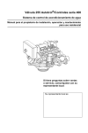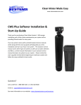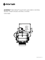
1
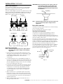
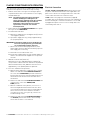
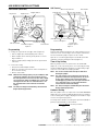
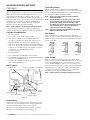
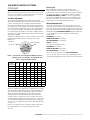
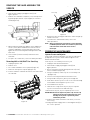
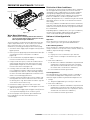
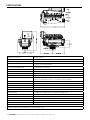
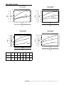
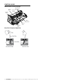
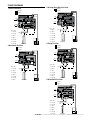
Autotrol® Performa™ Valve with 400 Series Control
Water Conditioning Control System
Service Manual
460TC
460TC
BRINE/
SLOW RINSE
DAYS
CLOCK
BACKWASH
FAST RINSE/
CONDITIONED WATER
REFILL
MANUAL REGENERATION:
PRESS BUTTON & RELEASE
PRESS
TO SET TIME
www.pentairaqua.com
INSTALLATION
INSTALLATION......................................................................2
PLACING CONDITIONER INTO OPERATION.........................4
400 SERIES CONTROL SETTINGS........................................5
REMOVING THE VALVE ASSEMBLY FOR SERVICE...............8
PREVENTIVE MAINTENANCE...............................................8
SPECIFICATIONS................................................................ 10
PRESSURE GRAPHS........................................................... 11
CONTROL VALVE................................................................. 12
FLOW DIAGRAMS................................................................ 13
REPLACEMENT PARTS....................................................... 14
TROUBLESHOOTING........................................................... 16
All plumbing and electrical connections must conform to local
codes.
Inspect unit carefully for carrier shortage or shipping damage.
The 268 water conditioner’s control valve
A N D CE R T
I
ED
conforms to NSF/ANSI 44 and 61 for materials
and structural integrity only. Generic systems
were tested and certified by WQA as verified by
the performance data sheet.
DU
D
ER
IN
AR
U ND
DS
TES
T
D
FIE
TABLE OF CONTENTS
A
ST R Y ST
N
Location Selection
1. The distance between the unit and a drain should be as
short as possible.
2. If it is likely that supplementary water treatment
equipment will be required, make certain adequate
additional space is available.
3. Since salt must be added periodically to the brine tank, the
location should be easily accessible.
4. Do not install any unit closer to a water heater than a total
run of 10 feet (3 m) of piping between the outlet of the
conditioner and the inlet to the heater. Water heaters can
sometimes overheat to the extent they will transmit heat
back down the cold pipe into the unit control valve.
Hot water can severely damage the conditioner. A
10 foot (3 m) total pipe run, including bends, elbows, etc.,
is a reasonable distance to help prevent this possibility. A
positive way to prevent hot water flowing from heat source
to the conditioner, in the event of a negative pressure
situation, is to install a check valve in the soft water piping
from the conditioner. If a check valve is installed, make
certain the water heating unit is equipped with a properly
rated temperature and pressure safety relief valve. Also, be
certain that local codes are not violated.
5. Do not locate unit where it or its connections (including the
drain and overflow lines) will ever be subjected to room
temperatures under 34°F (1°C) or over 120°F (49°C).
6. Do not install unit near acid or acid fumes.
7. The use of resin cleaners in an unvented enclosure is
not recommended.
California Proposition 65 Warning
WARNING: This product contains chemicals known to the
State of California to cause cancer or birth
defects or other reproductive harm.
2 • Autotrol Performa Valve with 400 Series Control Water Conditioning Control System
®
INSTALLATION continued
Water Line Connection
The installation of a bypass valve system is recommended to
provide for occasions when the water conditioner must be
bypassed for hard water or for servicing.
The most common bypass systems are the Autotrol Series 1265
bypass valve (Figure 1) and plumbed-in globe valves (Figure 2).
Though both are similar in function, the Autotrol Series 1265
bypass offers simplicity and ease of operation.
Not in Bypass
In
Out
IMPORTANT: Never insert drain line into a drain, sewer line
or trap. Always allow an air gap between the
drain line and the wastewater to prevent the
possibility of sewage being back-siphoned into
the conditioner.
Right Way
In Bypass
In
Out
Figure 3
NOTE: Standard commercial practices have been expressed
BY
PA S S
BY
PA S S
BY
BY
PA S S
PA S S
here. Local codes may require changes to these
suggestions.
Brine Line Connection
Water
Conditioner
It will be necessary to install the brine line to the brine fitting
on the valve (3/8-inch NPT).
Be sure all fittings and connections are tight.
Water
Conditioner
Figure 1 Autotrol Series 1265 Bypass Valve
Not in Bypass
Water
Conditioner
Overflow Line Connection
In the absence of a safety overflow and in the event of
a malfunction, the BRINE TANK OVERFLOW will direct
“overflow” to the drain instead of spilling on the floor where it
could cause considerable damage. This fitting should be on the
side of the cabinet or brine tank.
To connect overflow, locate hole on side of brine tank. Insert
overflow fitting (not supplied) into tank and tighten with plastic
thumb nut and gasket as shown (Figure 4). Attach length of
1/2 inch (1.3 cm) I.D. tubing (not supplied) to fitting and run to
drain. Do not elevate overflow line higher than 3 inches
(7.6 cm) below bottom of overflow fitting. Do not tie into drain
line of control unit. Overflow line must be a direct, separate
line from overflow fitting to drain, sewer or tub. Allow an air
gap as per drain line instructions (Figure 3).
In Bypass
Water
Conditioner
Figure 2 Typical Globe Valve Bypass System
Drain Line Connection
NOTE: Standard commercial practices are expressed here.
Local codes may require changes to the following
suggestions.
1. Ideally located, the unit will be above and not more than
20 feet (6.1 m) from the drain. For such installations, using
an appropriate adapter fitting, connect 1/2 inch (1.3 cm)
plastic tubing to the drain line connection of the
control valve.
2. If the backwash flow rate exceeds 5 gpm (22.7 Lpm) or if
the unit is located more than 20 feet (6.1 m) from drain, use
3/4 inch (1.9 cm) tubing for runs up to 40 feet (12.2 m). Also,
purchase appropriate fitting to connect the 3/4 inch tubing
to the 3/4 inch NPT drain connection.
Overflow Fitting
Installed
Brine Tank
Connect 1/2-inch
(1.3 cm) Tubing or
Hose and Run to
Drain
Figure 4
3. If the unit is located where the drain line must be elevated,
you may elevate the line up to 6 feet (1.8 m) providing the
run does not exceed 15 feet (4.6 m) and water pressure
at conditioner is not less than 40 psi (2.76 bar). You may
elevate an additional 2 feet (61 cm) for each additional
10 psi (0.69 bar).
4. Where the drain line is elevated but empties into a drain
below the level of the control valve, form a 7 inch (18 cm)
loop at the far end of the line so that the bottom of the loop
is level with the drain line connection. This will provide an
adequate siphon trap.
5. Where the drain empties into an overhead sewer line, a
sink-type trap must be used.
Autotrol Performa Valve with 400 Series Control Water Conditioning Control System • 3
®
PLACING CONDITIONER INTO OPERATION
After all previous steps have been completed, the unit is ready
to be placed into operation. Follow these steps carefully.
1. Remove control valve cover by first releasing the plastic
clip from the back of the cover. Pull back of cover slightly
outward and lift up.
NOTE: The following steps will require turning the
indicator knob (Figure 5 and Figure 6) to
various positions. Manually rotate the camshaft
COUNTERCLOCKWISE only until indicator
knob points to desired position. See manual
regeneration sections for each control’s
manual operation.
Electrical Connection
100 VAC, 115 VAC, and 230 VAC units: Remove twist tie from
the power cord and extend cord to its full length. Make sure
power source matches the rating printed on the control. Be
certain a wall switch does not control the outlet.
12 VAC: Connect the plug of the transformer (supplied)
secondary cable to the mating socket at the rear or bottom of
the timer housing. Be certain the transformer is secure and
is plugged into a power source of correct voltage that is not
controlled by a wall switch.
2. Rotate indicator knob COUNTERCLOCKWISE until it points
directly to the word BACKWASH.
3. Fill media tank with water.
A. With water supply off, place the bypass valve(s) into the
“not in bypass” position.
B. Open water supply valve very slowly to approximately
the 1/4 open position.
IMPORTANT: If opened too rapidly or too far, media may be
lost. In the 1/4 open position, you should hear
air escaping slowly from the drain line.
C. When all of the air has been purged from the tank
(water begins to flow steadily from the drain), open the
main supply valve all the way.
D. Allow water to run to drain until clear.
E.Turn off water supply and let the unit stand for about five
minutes. This will allow all trapped air to escape from
the tank.
4. Add water to brine tank (initial fill).
With a bucket or hose, add approximately 4 gallons (15
liters) of water to brine tank. If the tank has a salt platform
above the bottom of the tank, add water until the level is
approximately 1 inch (25 mm) above the platform.
5. Place the conditioner into operation.
A. With the water supply valve completely open, carefully
advance the indicator knob COUNTERCLOCKWISE to
the center of the BRINE REFILL position. Hold at this
position until water starts to flow through the brine line
into the brine tank. Do not run for more than one or
two minutes.
B. Advance the indicator knob COUNTERCLOCKWISE until
it points to the center of the BRINE/SLOW
RINSE position.
C. With the conditioner in this position, check to see if
water is being drawn from the brine tank. The water
level in the brine tank will recede very slowly. Observe
water level for at least three minutes. If the water
level does not recede, or if it goes up, reference the
Troubleshooting section.
D. Advance the indicator knob COUNTERCLOCKWISE to
the SERVICE position and run water from a nearby
faucet until the water is clear and soft.
4 • Autotrol Performa Valve with 400 Series Control Water Conditioning Control System
®
400 SERIES CONTROL SETTINGS
460i Control
440i Control (obsolete)
Day Arrow
Skipper Pins
Water Flow Indicator
PM Indicator
Skipper Wheel
Raised Tab
Hour Time Display
Access
Door
Jumper
Indicator Knob
Time Arrow
Timer Locking Pin
Timer Knob
Figure 5
Spare
Time Set Button
Indicator Knob
Jumper
Timer Locking Pin
Transformer
Plug Receptacle
Figure 6
Programming
Programming
1. Set days of regeneration on skipper wheel (Figure 5).
• Pull all skipper pins outward (away from control).
• Rotate skipper wheel until day arrow points to current
day or number 1.
• Depress skipper pin(s) at day(s) for which regeneration
is desired.
Plug the wall-mount transformer into a functioning electrical
outlet that is not controlled by a switch. Plug the transformer
into the transformer plug receptacle on the control.
Open the access door by pushing the raised tab on the door
toward the left while pulling the tab out (Figure 6).
Time of Day Setting
2. Set the time of day.
• Grasp timer knob and pull outward.
• Rotate in either direction until the timer arrow points to
the actual time of day.
• Release timer knob.
NOTE: With the time of day properly set, the conditioner will
regenerate at about 2:30 a.m. If you prefer to have
the unit regenerate at an earlier or later time, simply
set current time-of-day accordingly (e.g., to have the
unit regenerate at 4:30 a.m.—two hours later—set
the clock two hours earlier than the actual time
of day).
NOTE: The Timer Locking Pin should always be horizontal
(Figure 5) during operation.
With the jumper on the set of pins next to the word TIME
(Figure 7), set the time of day to the closest hour by pressing
the black TIME SET button. PM hours are indicated by a light
next to the letters PM on the display window.
NOTE: The use of a small needle-nose pliers will aid in
moving the jumper.
NOTE: The unit is factory set to regenerate at 2:00 a.m. If
you prefer to have the unit regenerate at an earlier
or later time, simply set the current time of day
accordingly (e.g., to have the unit regenerate at 4:00
a.m.—two hours later—set the clock two hours
earlier than the actual time of day).
NOTE: The Timer Locking Pin should always be horizontal
(Figure 6) during operation.
Hardness Setting
Move the jumper to the set of pins next to the word HARDNESS
(Figure 8). Press the black TIME SET button until the hardness
of the incoming water supply is displayed. The hardness range
is from 1 to 99 grains per gallon.
To change water hardness stated in parts per million (PPM) to
grains per gallon (GPG) use this formula:
Parts per Million = Grains per Gallon
17.1
Figure 7
Figure 8
Figure 9
Autotrol Performa Valve with 400 Series Control Water Conditioning Control System • 5
®
400 SERIES CONTROL SETTINGS
continued
Time of Day Setting
Capacity Setting
Move the jumper to the set of pins next to the word CAPACITY
(Figure 9). Press the black TIME SET button until the correct
capacity value is displayed. The capacity range is 1 to 99
kilograins. Refer to the Suggested Salt Dial Settings table (1).
Return the jumper to the top set of pins next to the word TIME
and replace the access door. The jumper must NOT be left
on any pins other than the top pair next to the word TIME.
Otherwise, the unit may show a blank display.
NOTE: A spare jumper is located on the bottom set of pins.
In the event that the hardness or capacity setting must be
changed, simply follow the appropriate steps described above.
Calendar Override Setting
Days Setting
1. Disconnect power.
2. Place jumper on Pin A and reconnect power.
3. Move jumper to Pin B. A zero will appear, indicating
zero days of calendar override. All 460i controllers are
preprogrammed in this manner at the manufacturer.
4. Depress the black TIME SET button. The numbers will roll
from “0” to “15.” Release the switch at the desired number
of days for the calendar override. For example, releasing
the switch at “10” would program a 10-day
calendar override.
5. Disconnect power.
7. The calendar override program is maintained during power
outages by the NOVRAM circuitry.
8. To remove the calendar override, follow the same steps
above and program back to “0.”
460TC Control
Hour Time Display
Raised Tab
Access
Door
460TC
Move the jumper to the set of pins next to the word DAYS
(Figure 12). Press the black TIME SET button until the desired
number of days between regeneration is displayed. The range
is from 1 to 30 days.
TIME
DAYS
CLOCK
Figure 11
6. Place jumper back on TIME and reconnect power.
PM Indicator
With the jumper on the set of pins next to the word TIME
(Figure 11), set the time of day to the closest hour by pressing
the black TIME SET button. PM hours are indicated by a light
next to the letters PM on the display window.
NOTE: The use of a small needle-nose pliers will aid in
moving the jumper.
NOTE: The unit is factory set to regenerate at 2:00 a.m. If
you prefer to have the unit regenerate at an earlier
or later time, simply set the current time of day
accordingly (e.g., to have the unit regenerate at 4:00
a.m.—two hours later—set the clock two hours
earlier than the actual time of day).
NOTE: The Timer Locking Pin should always be horizontal
(Figure 10) during operation.
Clock Setting
Jumper
Spare
Jumper
Time Set Button
Transformer
Plug Receptacle
Timer Locking Pin
Figure 10
Programming
Plug the wall-mount transformer into a functioning electrical
outlet that is not controlled by a switch. Plug the transformer
into the transformer plug receptacle on the control.
Open the access door by pushing the raised tab on the door
toward the left while pulling the tab out (Figure 10).
6 • Autotrol Performa Valve with 400 Series Control Water Conditioning Control System
®
Figure 12
TIME
DAYS
CLOCK
Figure 13
Move the jumper to the set of pins next to the word CLOCK
(Figure 13). Press the black TIME SET button until the desired
clock setting is displayed. The clock range is 0 or 1. Select 0
for the standard AM/PM clock or select 1 for a 24 hour clock.
Return the jumper to the top set of pins next to the word TIME
and replace the access door. The jumper must NOT be left
on any pins other than the top pair next to the word TIME.
Otherwise, the unit may show a blank display.
NOTE: A spare jumper is located on the bottom set of pins.
DAYS
CLOCK
Indicator Knob
TIME
DAYS
CLOCK
400 SERIES CONTROL SETTINGS
continued
Guest Cycle
Common Features
When using the Performa valve with the 440i or 460i controls,
there are several features and procedures that are unique to
the 400 series controls. They are as follows:
Salt Dial Adjustment
These models may be adjusted to produce maximum to
minimum conditioning capacities by setting the salt dial, which
controls the amount of salt used per regeneration. When
desired, the minimum setting may be used on installations if
the frequency of regeneration is increased to compensate for
lower regenerated conditioning capacity. The installing dealer
will set the unit for proper salt usage. Further adjustments
are needed only if the hardness of the water supply changes
or if water use changes dramatically. Capacity will need to be
adjusted accordingly.
To adjust salt dosage, insert a small screwdriver into the white
indicator knob and move pointer to proper salt setting
(Figure 14).
Pounds of
Salt Used
Indicator Knob
Figure 14
NOTE: To convert the salt settings from English to metric,
divide by 2.2 (e.g., 12 pounds ÷ 2.2 = 5.5 kg of salt).
When abnormally high water usage exhausts your
water conditioner’s capacity ahead of schedule, an extra
regeneration can be achieved. Depress the indicator knob on
the 440i (Figure 5) with a wide-blade screwdriver and turn
COUNTERCLOCKWISE to START to initiate a regeneration.
For the 460i, simply depress the indicator knob (Figure 6). It
will take a few minutes for regeneration to start. A normal
regeneration will take approximately two hours.
Manual Regeneration
Electricity is used only to run the control and to rotate the
camshaft. All other functions are operated by water pressure.
Therefore, in the event of a power outage, all the regeneration
positions may be dialed manually by depressing the indicator
knob and turning COUNTERCLOCKWISE (Figure 5 and Figure
6). The following cycle times should be used for proper
regeneration:
BACKWASH—14 minutes
BRINE/SLOW RINSE—52 minutes
FAST RINSE/REFILL—10 minutes
PURGE—6 minutes
Cycle times for FA applications:
BACKWASH—20 minutes
BRINE/SLOW RINSE—50 minutes
FAST RINSE/REFILL—10 minutes
Do not exceed 10 minutes for the FAST RINSE/REFILL
cycle as this will cause excessive salt usage during the next
regeneration and possibly a salt residue in the softened water.
Table 1 - Suggested Salt Dial Settings
Capacity
Setting
(Kilograins)
0.5
ft3
12
16
0.75
ft3
1.0
ft3
1.25
ft3
1.5
ft3
1.75
ft3
2.0
ft3
2.5
ft3
4.5
–
–
–
–
–
–
–
9.0
5.5
–
–
–
–
–
–
20
–
8.5
6.0
–
–
–
–
–
24
–
14.0
8.5
7.0
–
–
–
–
30
–
–
15.0
11.0
9.0
–
–
–
32
–
–
18.5
12.5
10.0
9.0
–
–
35
–
–
–
16.0
12.0
10.0
9.0
–
40
–
–
–
23.0*
17.0
14.0
12.0
–
48
–
–
–
–
28.0*
21.0*
17.0
14.0
60
–
–
–
–
–
–
30.0*
21.0*
*When using the 440i or 460i you must use Extra Salt cam and
divide the suggested setting by 2 to accomplish these settings.
The amount of salt placed in the brine tank has nothing to do
with the amount of salt used during the regeneration cycle.
Water will dissolve and absorb salt only until it becomes
saturated. A given amount of brine (salt-saturated water)
contains a specific amount of salt. The salt dial controls the
amount of brine used during the regeneration cycle (e.g., when
set at 15 pounds (6.8 kg) the amount of brine the conditioner
will use for each regeneration will contain 15 pounds (6.8 kg)
of salt, etc.)
Never let the amount of salt in the brine tank fall lower than
the normal liquid level. Do not overload the brine tank
with salt.
Autotrol Performa Valve with 400 Series Control Water Conditioning Control System • 7
®
REMOVING THE VALVE ASSEMBLY FOR
SERVICE
1. Unplug the power cord.
2. Shut off water supply or put bypass valve(s) into
bypass position.
Lever Up
3. Remove cover and with screwdriver, relieve tank pressure
by pushing open valve No. 7 (rear flapper) on control as
shown (Figure 15).
Cam Pulled Out
Figure 17
6. Remove the timer locking pin and lift the control straight up
and off of the valve.
Figure 15
4. When used with a globe valve bypass, loosen and detach
the inlet, outlet, brine and drain lines from the valve. If
using the 1265 bypass, loosen and remove valve from
bypass as well as loosening and removing the brine and
drain lines.
5. Unscrew valve (counterclockwise) and remove valve
from tank.
6. To replace the control valve, reverse the above procedure.
Removing 440i or 460i/460TC for Servicing
1. Unplug the power cord.
2. Remove cover.
3. The control should be in service position (Figure 16).
4. Rotate the locking lever to point up (Figure 17).
5. Pull the end of the camshaft out from the lever and remove
the camshaft.
7. To reinstall the camshaft and control, reverse the
above procedures.
NOTE: When reinstalling the camshaft the control should be
in SERVICE position. When the camshaft is positioned,
cams will make contact with valves to force
them open.
PREVENTIVE MAINTENANCE
Injector Screen and Injector
Inspect and clean brine tank and screen filter on end of brine
pickup tube once a year or when sediment appears in the
bottom of the brine tank.
Clean injector screen and injector once a year:
1. Unplug the wall-mount transformer.
2. Shut off water supply or put bypass valve(s) into
bypass position.
3. Relieve system pressure by opening valve No. 7 (at rear)
with a screwdriver (Figure 15).
4. Using a screwdriver, remove injector screen and injector
cap (Figure 18).
5. Clean screen using a fine brush. Flush until clean.
6. Using a needle-nose pliers, pull injector straight out.
7. Flush water into the injector screen recess of the valve body
to flush debris out through the injector recess.
Lever Down
8. Clean and flush the injector.
9. Lubricate the o-rings on the injector, injector cap and
injector screen with silicone lubricant only!
10.Reinstall the injector, injector cap and injector screen.
Figure 16
IMPORTANT: Do not overtighten the plastic cap. Seat the cap
lightly into position. Overtightening may cause
breakage of the plastic cap that may not be
immediately evident.
11.Plug the wall-mount transformer into outlet; reset clock
if necessary.
12.Slowly open water supply valve or return bypass valve(s) to
the “service” position.
8 • Autotrol Performa Valve with 400 Series Control Water Conditioning Control System
®
PREVENTIVE MAINTENANCE continued
Injector Screen
Turbine
Injector
Cap
Figure 18
Water Meter Maintenance
NOTE: A water meter is used only with the 460i control. If
you are using the 440i or 460TC control, this section
does not pertain to your conditioner.
The metering device used with the 460i demand control may
require simple maintenance. In rare instances, the turbine
wheel of the water meter can collect small particles of
oxidized iron, eventually preventing the wheel from turning.
1. Shut off the water supply or put the bypass valve(s) into the
bypass position.
2. Relieve pressure by opening the Backwash Drain Valve (the
seventh back from the control) with a screwdriver
(Figure 15).
3. Loosen and remove the pipe/tube adapters or 1265 bypass
from the inlet and outlet of the valve body.
4. Using a needle-nose pliers, remove the turbine from the
outlet housing. Grasp one of the four vanes of the outer
gland and pull straight out to remove turbine assembly
from the outlet of the valve (Figure 18).
5. Carefully remove the turbine wheel from the housing.
Use a toothbrush to lightly scrub the iron off the magnet.
Iron buildup on the surfaces can be removed by soaking
the wheel in a mild sodium hydrosulfite solution for a few
minutes. Flush thoroughly with water.
6. Carefully reinstall the turbine wheel into the turbine cage
housing. Make sure that the shaft of the wheel seats into
the bearing of the cage. Reassemble the turbine cage and
check that the wheel rotates freely.
7. Reinstall the turbine cage into the outlet of the valve.
8. Reinstall the pipe/tube adapters or 1265 bypass to the inlet
and outlet of the valve.
9. Turn on the water supply or put the bypass valve(s) into the
service position and purge the air out of the system.
To check for proper meter operation, open a downstream
faucet and observe the water flow indication on the
control display.
Disinfection of Water Conditioners
The materials of construction of the modern water conditioner
will not support bacterial growth, nor will these materials
contaminate a water supply. However, the normal conditions
existing during shipping, storage and installation indicate
the advisability of disinfecting a conditioner after installation,
before the conditioner is used to treat potable water. In
addition, during normal use, a conditioner may become fouled
with organic matter or in some cases with bacteria from the
water supply.
Thus every conditioner should be disinfected after installation,
some will require periodic disinfection during their normal life,
and in a few cases disinfection with every regeneration would
be recommended.
Depending upon the conditions of use, the style of conditioner,
the type of ion exchanger, and the disinfectant available, a
choice can be made among the following methods.
Sodium or Calcium Hypochlorite
Application
These materials are satisfactory for use with polystyrene
resins, synthetic gel zeolite, greensand and bentonites.
5.25% Sodium Hypochlorite
These solutions are commonly known as household bleach. If
stronger solutions are used, such as those sold for commercial
laundries, adjust the dosage accordingly.
1. Dosage
A. Polystyrene resin: 1.2 fluid ounces per cubic foot.
B. Non-resinous exchangers: 0.8 fluid ounce per cubic
foot.
2. Brine tank conditioners
A. Backwash the conditioner and add the required amount
of hypochlorite solution to the brine well of the brine
tank. (The brine tank should have water in it to permit
the solution to be carried into the conditioner.)
B. Proceed with the normal regeneration.
Calcium Hypochlorite
Calcium hypochlorite, 70% available chlorine, is available in
several forms including tablets and granules. These solid
materials may be used directly without dissolving before use.
1. Dosage
A. Two grains (approximately 0.1 ounce) per cubic foot.
2. Brine tank conditioners
A. Backwash the conditioner and add the required amount
of hypochlorite to the brine well of the brine tank. (The
brine tank should have water in it to permit the chlorine
solution to be carried into the conditioner.)
B. Proceed with the normal regeneration.
Autotrol Performa Valve with 400 Series Control Water Conditioning Control System • 9
®
SPECIFICATIONS
DAYS
CLOCK
Hydrostatic Test Pressure
300 psi (20.69 bar)
Working Pressure
20-125 psi (1.38 - 8.62 bar)
Standard Electrical Rating
115V 60 Hz
Optional Electrical Rating
115V 50 Hz, 230V 50 Hz, 200V 60Hz, 24V 60 Hz, 24V 50 Hz, 100V 60 Hz, 100V 50 Hz, 12V 50 Hz/
transformer, 12V 60 Hz/transformer
Electrical Cord (standard rating)
60-inch (1.5 m) 3-wire with plug
Pressure Tank Thread
2-1/2 inch-8 male
Riser Pipe Diameter Required
1.050 inch OD (26.7 mm)
Riser Pipe Length
1-1/8 ±1/8 inches (31.8 mm) higher than the top of mineral tank
Standard Connection
1-inch (25.4-mm) copper tube adapters
Optional Connections
3/4-inch, 22-mm, and 28-mm copper tube adapters 3/4-inch BSPT, 1-inch BSPT, 1-inch NPT
stainless steel pipe adapters 3/4-inch, 1-inch, 25-mm CPVC tube adapters
Brine Line Connection
3/8-inch NPT male
Drain Line Connection
3/4-inch NPT male
Optional Bypass Valve
Rotating handles, full 1-inch porting, reinforced plastic
Control Module, Tank Adapter
Reinforced plastic
Rubber Goods
Compounded for cold water service
Brine Refill Control
1 to 10 lbs (0.45 to 4.5 kg) of salt or 3 to 19 lbs (1.4 to 8.6 kg) of salt
Injector Size “A” White
Nozzle .042-inch (1.1 mm) diameter, Throat .089-inch (2.3 mm) diameter
Injector Size “B” Blue
Nozzle .052-inch (1.3 mm) diameter, Throat .099-inch (2.5 mm) diameter
Injector Size “C” Red
Nozzle .059-inch (1.5 mm) diameter, Throat .099-inch (2.5 mm) diameter
Injector Size "D" Green
Nozzle .071-inch (1.8 mm) diameter, Throat .147-inch (3.7 mm) diameter
Internal Backwash Controllers
7- through 14-inch (17.8 though 35.6 cm) diameter media tanks
All sizes to flow 4.5 gpm/sq ft (183 L/m/m2) of bed area.
For tank sizes above 14 inches in diameter, use an external flow control.
10 • Autotrol Performa Valve with 400 Series Control Water Conditioning Control System
®
PRESSURE GRAPHS
Injector #1031363
Injector #1031364
"A" in a 268 Valve
"B" in a 268 Valve
1.00
0.30
Total
M3/hr
0.50
Brine Draw
0.05
0.25
0.00
0.00
20
40
60
400 600
PSI
80
100
120
0.15
Total
1.00
0.20
Rinse
GPM
M3/hr
0.15
0.10
1.25
0.25
0.75
Rinse
0.75
GPM
0.20
0.10
0.50
0.05
0.25
0.00
0.00
Brine Draw
20
800 1000 1200 1400 1600 1800
bar
40
400 600
0.25
Total
1.25
0.20
0.10
0.05
0.00
M3/hr
Rinse
1.00
0.75
0.15
0.10
Brine Draw
0.50
0.05
0.25
0.00
0.00
20
40
60
400 600
PSI
80
100
120
800 1000 1200 1400 1600 1800
bar
100
120
800 1000 1200 1400 1600 1800
bar
Backwash
Number
7
8
9
10
12
13
14
Flow
(GPM*)
1.2
1.6
2.0
2.5
3.5
4.1
4.8
Flow
(LPM*)
4.5
6.0
7.6
9.5
13.2
15.5
18.2
2.25
2.00
1.75
1.50
1.25
1.00
0.75
0.50
0.25
0.00
Total
Rinse
GPM
0.30
1.75
GPM
M3/hr
0.15
80
"D" in a 268 Valve
"C" in a 268 Valve
1.50
PSI
Injector #1030272
Injector #1031365
0.20
60
Brine Draw
20
40
400 600
60
PSI
80
100
120
800 1000 1200 1400 1600 1800
bar
*Approximate flow rates at 60 psi (4.14 bar)
Autotrol Performa Valve with 400 Series Control Water Conditioning Control System • 11
®
CONTROL VALVE
Identification of Control Valving
7 Backwash
Drain Valve
5 Refill
Valve
3 Inlet
Valve
1 Brine
Valve
6 Rinse
Drain Valve
2 Bypass
Valve
4 Outlet
Valve
Valve Disc Principle of Operation
12 • Autotrol Performa Valve with 400 Series Control Water Conditioning Control System
®
FLOW DIAGRAMS
3 Brining/Slow Rinse Position
1 Service Position
Hard Water
Soft Water
Hard Water
Soft Water
Brine
Adjustment
1
Inlet
Inlet
3
2
3
2
5
Outlet
5
Outlet
Brine
Adjustment
1
4
6
4
6
7
7
Valve No.
1 - Open
Valve No.
1 - Closed
Drain
2 - Open
Drain
2 - Closed
3 - Closed
3 - Open
4 - Closed
4 - Open
5 - Closed
5 - Closed
6 - Open
6 - Closed
7 - Closed
7 - Closed
Mineral Tank
Brine Tank
4 Purge Position
Brine Tank
2 Backwash Position
Mineral Tank
Hard Water
Soft Water
Hard Water
Soft Water
Brine
Adjustment
1
Brine
Adjustment
1
Inlet
Inlet
2
5
Outlet
5
Outlet
3
2
3
4
6
7
4
6
7
Backwash
Flow
Control
Valve No.
1 - Closed
Valve No.
1 - Closed
2 - Open
Drain
2 - Open
3 - Open
3 - Closed
4 - Closed
4 - Open
5 - Closed
5 - Closed
6 - Open
6 - Closed
7 - Closed
7 - Open
Drain
Mineral Tank
Mineral Tank
Brine Tank
5 Brine Refill Position
Brine Tank
Hard Water
Soft Water
Brine
Adjustment
1
Inlet
3
2
5
Outlet
4
6
7
Valve No.
1 - Closed
Drain
2 - Closed
3 - Open
4 - Open
5 - Open
6 - Closed
7 - Closed
Mineral Tank
Brine Tank
Autotrol Performa Valve with 400 Series Control Water Conditioning Control System • 13
®
REPLACEMENT PARTS
4
2
5
13
13
16
15
14
9
10
3
1
6
7
12
6
19
14
8
3
12
Item No.
QTY
Part No.
8
17
11
Description
1����������������� 1���������1035606���������������Valve Assembly, w/o Flow Controls
(460i, 460TC)
2����������������� 1�������������������������������������Camshaft:
Item No.
QTY
Part No.
Description
11��������������� 1���������1010429���������������O-Ring
12��������������� 1���������1035622���������������Tank Ring
13��������������� 1�������������������������������������Plumbing Adapter Kits:
����������1035625���������������440i, 460i Standard
����������1001606���������������3/4-inch Copper Tube Adapter Kit
����������1035627���������������440i, 460i Extra Salt **
����������1001670���������������1-inch Copper Tube Adapter Kit
����������1030376���������������440i, FA
����������1041210���������������1-1/4 inch Copper Tube Adapter Kit
3����������������� 1���������1031391���������������Timer Locking Pin
����������1001608���������������22-mm Copper Tube Adapter Kit
4����������������� 1�������������������������������������Drain Control Assembly:
����������1001609���������������28-mm Copper Tube Adapter Kit
����������1000209���������������No. 7 (1.2 gpm; 4.5 Lpm)
����������1001613���������������3/4-inch CPVC Tube Adapter Kit
����������1000210���������������No. 8 (1.6 gpm; 6.1 Lpm)
����������1001614���������������1-inch CPVC Tube Adapter Kit
����������1000211���������������No. 9 (2.0 gpm; 7.6 Lpm)
����������1001615���������������25-mm CPVC Tube Adapter Kit
����������1000212���������������No. 10 (2.5 gpm; 9.5 Lpm)
����������1000213���������������No. 12 (3.5 gpm; 13.2 Lpm)
����������1001769���������������3/4-inch NPT Plastic Pipe Adapter
Kit
����������1000214���������������No. 13 (4.1 gpm; 15.5 Lpm)
����������1001603���������������1-inch NPT Plastic Pipe Adapter Kit
����������1000215���������������No. 14 (4.8 gpm; 18.2 Lpm)
����������1001604���������������3/4-inch BSPT Plastic Pipe Adapter
Kit
����������1001605���������������1-inch BSPT Plastic Pipe Adapter
Kit
����������3023824���������������3/4-inch BSPT S.S. Pipe Adapter
Kit
����������3023828���������������1-inch NPT S.S. Pipe Adapter Kit
����������3023807���������������1-inch BSPT S.S. Pipe Adapter Kit
5����������������� 2���������1030502���������������Ball, Flow Control
6����������������� 1�������������������������������������Injector Assembly:
����������1032970���������������“A” Injector - White
����������1032971���������������“B” Injector - Blue
����������1032972���������������“C” Injector - Red
����������1030272���������������“D” Injector - Green
7����������������� 1�������������������������������������Injector Cap Assembly:
14��������������� 1���������1033444���������������Turbine Assembly (460i only)
15��������������� 1���������1235339���������������Spring, one pc 268
����������1000217���������������“A” Cap
����������1000218���������������“B” Cap
17��������������� 1���������1232370���������������O-Ring, Riser Tube
����������1000219���������������“C” Cap
Not Shown:
����������1030303���������������“D” Cap
16��������������� 1���������3019874���������������Lever, Locking Cam 268
1���������3019870���������������I-Lid Cover
8����������������� 1�������������������������������������Brine Refill Control (440i and 460i):
1�������������������������������������Valve Disc Kit:
����������1034261���������������1 to 10 Pounds Salt
����������1041174���������������Standard
����������1034263���������������3 to 19 Pounds Salt
����������1041175���������������Severe Service
9����������������� 1���������1002449���������������Drain Fitting Elbow (3/4-inch hose
barbed)
10��������������� 1���������1000226���������������Screen/Cap Assembly
* Not Shown
** Soft water refill is not available with the extra salt cam
14 • Autotrol Performa Valve with 400 Series Control Water Conditioning Control System
®
REPLACEMENT PARTS continued
460TC Control (3)
440i Control (obsolete)(1)
460TC
DAYS
CLOCK
1265 Bypass (4)
460i Control (2)
B Y PA S S
B Y PA S S
Item No.
QTY
Part No.
Description
1����������������1�����������������������������������440i Control (6 day or 7 day)
2����������������1�����������������������������������460i Control
3����������������1�������� 4001086�������������460TC Control
4����������������1�������� 1040930�������������1265 Bypass
Not Shown:
1�������� 1000811�������������Transformer (440i, 460i):
1�������� 1000907�������������Transformer Extension Cord
15 feet (4.6 m)
1�������� 1034264�������������Y-Splitter (run 2 units from
1 transformer)
1�������� 1007776�������������Jumper
Autotrol Performa Valve with 400 Series Control Water Conditioning Control System • 15
®
TROUBLESHOOTING
The technology upon which the Autotrol Performa control valve
is based is well established and proven in service over many
years. However, should a problem or question arise regarding
the operation of the system, the control can very easily be
serviced. For parts mentioned, refer to exploded views in the
Replacement Parts section of this manual.
IMPORTANT: Service procedures that require the water
pressure to be removed from the system are
marked with a ! after the possible cause. To
remove water pressure from the system, put
the bypass valve or three-valve bypass into the
bypass position and open the backwash drain
valve (the seventh valve back from the control)
with a screwdriver. Restore system water
pressure when the service work is completed.
Valve Troubleshooting
Problem
Cause
Correction
Low water pressure.
Set pump to maintain 30 psi at conditioner.
Restricted drain line.
Remove restriction.
Injector plugged !
Clean injector and screen.
Injector defective !
Replace injector.
Valve (2 and/or 4) not closed.
Remove foreign matter from disc and check disc for
closing by pushing in on stem. Replace if needed.
Brine valve (1) being held open.
Manually operate valve stem to flush away obstruction.
Uncontrolled brine refill flow rate !
Remove variable salt controller to clean.
Valve (3 or 4) not closed during brine draw
causing refill.
Flush out foreign matter by holding disc open and
manually operating valve stem.
Air leak in brine line.
Check all connections in brine line for leaks. Refer to
instructions.
Inaccurate setting.
Correct setting.
System using more or less salt
than salt control is set for.
Foreign matter in controller causing incorrect
flow rates !
Remove variable salt controller and flush out foreign
matter. Manually position control to brine draw to
clean controller (after so doing, position control to
“purge” to remove brine from tank).
Defective controller.
Replace controller.
Intermittent or irregular brine
draw.
Low water pressure.
Set pump to maintain 30 psi at conditioner.
Control will not draw brine.
Brine tank overflow.
No conditioned water after
regeneration.
Control backwashes at excessively
low or high rate.
Flowing or dripping water at drain
or brine line after regeneration.
Hard water leakage during
service.
Defective injector !
Replace both injector and injector cap.
Unit did not regenerate.
Check for power.
No salt in brine tank.
Add salt.
Plugged injector !
Clean injector. Flush with water.
Incorrect backwash controller used.
Replace with correct size controller.
Foreign matter affecting controller operation !
Remove controller and ball. Flush with water.
Drain valve (5 or 6) or brine valve (1) held open
by foreign matter or particle.
Manually operate valve stem to flush away obstruction.
Valve stem return spring on top plate weak.
Replace spring.
Improper regeneration.
Repeat regeneration making certain that the correct
salt dosage is set.
Leaking of bypass valve !
Replace o-ring.
O-ring around riser tube damaged !
Replace o-ring.
16 • Autotrol Performa Valve with 400 Series Control Water Conditioning Control System
®
TROUBLESHOOTING continued
440i Control Troubleshooting
Problem
Control will not regenerate
automatically.
Control regenerates at wrong
time of day.
Cause
Correction
Transformer or motor not connected.
Connect power.
Defective timer motor.
Replace motor.
Skipper pins not down on timer skipper wheel.
Depress pins for days regeneration required.
Binding in gear train of timer.
Replace timer.
Time set incorrectly.
Correct time setting according to instructions.
460i/460TC Control Troubleshooting
Problem
Clock does not display time of day.
Clock does not display correct
time of day.
Time display continues to
advance.
Time display shows something
other than time of day.
No water flow display when water
is flowing (460TC has no meter).
Control regenerates at wrong
time of day.
Timer stalled in regeneration
cycle.
Cause
Correction
Transformer cord unplugged.
Connect power.
No electric power at outlet.
Repair outlet or use working outlet.
Defective transformer.
Replace transformer.
Defective circuit board.
Replace timer.
Outlet operated by switch.
Use outlet not controlled by switch.
Incorrect voltage or frequency (Hz).
Replace timer with one of correct voltage and
frequency (Hz).
Power outages.
Reset clock.
Defective time set switch.
Replace timer.
Electrical interference.
Disconnect power to unit. Restore power and reset
time of day.
Defective circuit board.
Replace timer.
Bypass valve in bypass.
Shift bypass valve to not-in-bypass position.
Meter probe disconnected or not fully connected
to meter housing.
Fully insert probe into meter housing (460TC has no
meter).
Restricted meter turbine rotation due to foreign
matter in meter.
Remove meter housing, free up turbine and flush with
clean water. Do not disassemble turbine from meter
housing. Turbine should spin freely. If not, replace
meter !
Defective meter probe.
Replace timer.
Defective circuit board.
Replace timer.
Power outages.
Reset clock to correct time of day.
Clock set incorrectly.
Reset clock to correct time of day.
Motor dead.
Replace timer.
Motor runs backward.
Replace timer.
No electric power at outlet.
Repair outlet or use working outlet.
Broken gear.
Replace timer.
Defective switch.
Replace timer.
Air leak in brine connections.
Check all junction points and make appropriate
corrections.
Binding of camshaft.
Remove foreign object obstruction from valve discs or
camshaft.
Water pressure greater than 125 psi during
regeneration.
Install pressure regulator !
Defective circuit board.
Replace timer.
Autotrol Performa Valve with 400 Series Control Water Conditioning Control System • 17
®
TROUBLESHOOTING continued
Problem
Cause
Correction
Continuous regeneration.
Camshaft does not stop at the end
of regeneration.
Broken switch activator on gear.
Replace timer.
Defective switch.
Replace timer.
Electric cord unplugged.
Connect power.
No electric power at outlet.
Repair outlet or use working outlet.
Defective motor.
Replace timer.
Broken gear.
Replace timer.
Binding in gear train.
Replace timer.
Defective switch.
Replace timer.
If water flow display is not operative, refer to
Item 5.
Same as Item 5.
Defective circuit board.
Replace timer.
Incorrect hardness and capacity settings.
Set to correct values. See Programming section.
Improper regeneration.
Repeat regeneration, making certain that correct salt
dosage is used.
Fouled softener resin.
Use resin cleaner. Use of resin cleaners in an unvented
enclosure is not recommended.
Incorrect salt setting.
Set salt control to proper level. See Salt Setting chart.
Incorrect harness or capacity settings.
Set to correct values. See Programming section.
Water hardness has increased.
Set hardness to new value. See Programming section.
Restricted meter turbine rotation due to foreign
material in meter housing.
Remove meter housing, free us turbine and flush with
clean water. DO NOT DISASSEMBLE TURBINE FROM
METER HOUSING. Turbine should spin freely, if not,
replace meter !
Excessive water usage below 1/5 gallon per
minute.
Repair leaky plumbing and/or fixtures !
Control will not regenerate
automatically or when button is
pressed.
Control will not regenerate
automatically but will regenerate
when button is pressed.
Run out of soft water between
regenerations.
18 • Autotrol Performa Valve with 400 Series Control Water Conditioning Control System
®
Autotrol Performa Valve with 400 Series Control Water Conditioning Control System • 19
®
For Autotrol® Product Warranties visit:
Autotrol® para las garantías de los productos visite:
Pour Autotrol® garanties produit visitez le site :
}
www.pentairaqua.com/pro
FILTRATION & PROCESS
5730 NORTH GLEN PARK ROAD, MILWAUKEE, WI 53209
P: 262.238.4400 | WWW.PENTAIRAQUA.COM | CUSTOMER CARE: 800.279.9404 | [email protected]
All Pentair trademarks and logos are owned by Pentair, Inc. or its affiliates. All other registered and unregistered trademarks and logos are the property of their
respective owners. Because we are continuously improving our products and services. Pentair reserves the right to change specifications without prior notice.
Pentair is an equal opportunity employer.
1222945 REV M FE14 © 2013 Pentair Residential Filtration, LLC All Rights Reserved