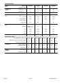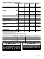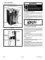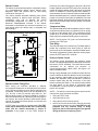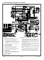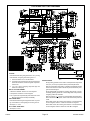
1
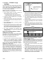
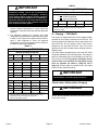
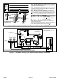
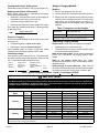
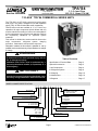
TPA*S4
3, 3.5, 4 and 5 ton
10.5, 12.3, 14 and 17.6 kW
Corp. 0632−L6
Revised 05−2009
Service Literature
T−CLASStTPA*S4 COMMERCIAL SERIES UNITS
The TPA*S4 is a HFC−410A commercial split-system
heat pump. The series is designed for use with expansion
valves (TXV). All TPA*S4 units utilize scroll compressors.
TPA*S4 series units are available in 3, 3.5, 4 and 5 ton
capacities. All major components (indoor blower and coil)
must be matched according to Lennox recommendations
for the compressor to be covered under warranty. Refer to
the Engineering Handbook for approved system
matchups.
This manual is divided into sections which discuss the
major components, refrigerant system, charging
procedure, maintenance and operation sequence.
Information contained in this manual is intended for use by
qualified service technicians only. All specifications are subject
to change.
WARNING
Improper installation, adjustment, alteration, service
or maintenance can cause personal injury, loss of
life, or damage to property.
Installation and service must be performed by a
licensed professional installer (or equivalent) or a
service agency.
IMPORTANT
This unit must be matched with an indoor coil as
specified in Lennox’ Engineering Handbook. Coils
previously charged with HCFC−22 must be flushed.
Table of Contents
Specifications / Electrical Data . . . . . . . . . Page 2
Optional Accessories . . . . . . . . . . . . . . . . . Page 3
I Unit Components . . . . . . . . . . . . . . . . . . . Page 4
II Refrigerant System . . . . . . . . . . . . . . . . . Page 8
III Charging . . . . . . . . . . . . . . . . . . . . . . . . . Page 10
IV Maintenance . . . . . . . . . . . . . . . . . . . . . . Page 16
V Diagrams . . . . . . . . . . . . . . . . . . . . . . . . . Page 17
MODEL NUMBER IDENTIFICATION
T P A 036 S 4 n 4 1 Y
Voltage
Y = 208/230V-3 phase-60hz
G = 460V-3 phase-60hz
Brand/Family
T = T−Classt Product Line
Minor Design Sequence
1 = 1st Revision
2 = 2nd Revision
3 = 3rd Revision
Unit Type
P = Heat Pump Outdoor Unit
Major Design Sequence
A = 1st Generation
B = 2nd Generation
Coil type
4 = Four−sided
Nominal Cooling Capacity − Tons
036 = 3 Tons
042 = 3.5 Tons
048 = 4 Tons
060 = 5 Tons
Part Load Capability
N = No part load, single stage compressor
Refrigerant Type
4 = R−410A
Cooling Efficiency
S = Standard Efficiency
Page 1
© 2006 Lennox Industries Inc.
SPECIFICATIONS
TPA036S4
TPA042S4
TPA048S4
TPA060S4
3
3.5
4
5
Liquid line o.d. − in.
3/8
3/8
3/8
3/8
Vapor line o.d. − in.
7/8
7/8
7/8
1-1/8
8 lbs. 12 oz.
10 lbs. 10 oz.
13 lbs. 2 oz.
15 lbs. 3 oz.
Model No.
General
Data
Nominal Tonnage
Connections
(sweat)
1 Refrigerant
HFC−410A charge furnished
Outdoor
Coil
Outdoor
Fan
Net face area Outer coil
sq. ft.
Inner coil
15.21
18.66
21.11
29.09
14.50
17.95
20.31
28.16
Tube diameter
5/16
5/16
5/16
5/16
Number of rows
2
2
2
2
Fins per inch
22
22
22
22
18 − 4
22 − 4
22 − 4
22 − 4
208/230V − 1/5
460V − 1/6
1/3
1/3
1/4
Cfm
2450
3890
3890
3830
Rpm
1100
1080
1085
830
Watts
190
400
375
330
180
220
250
255
Diameter − in. − No. of Blades
Motor hp
Shipping Data − lbs. 1 package
ELECTRICAL DATA
Line voltage data − 60 hz − 3ph 208/230V
2 Maximum
460V
208/230V
460V
208/230V
460V
208/230V
460V
20
15
30
15
30
15
35
15
circuit ampacity
14.2
7.8
18.6
8.3
18.8
8.6
21.3
10.7
Rated Load Amps
10.4
5.8
13.5
6.0
13.7
6.2
15.6
7.8
Locked Rotor Amps
88
38
88
44
83.1
41
110
52
Power Factor
.85
.84
.83
.81
.90
.92
.90
.91
Full Load Amps
1.1
.55
1.7
1.0
1.7
1.0
1.7
1.0
Locked Rotor Amps
1.9
1.1
4.1
2.2
4.1
2.2
3.1
2.3
overcurrent protection (amps)
3 Minimum
Compressor
Outdoor
Fan Motor
TPA*S4
Page 2
Revised 05−2009
OPTIONAL ACCESSORIES − must be ordered extra
Model No.
TPA036S4
TPA042S4
TPA048S4
TPA060S4
Compressor Low Ambient Cut−Off
45F08
S
S
S
S
Compressor Sound Cover
69J03
S
S
S
S
3/8 in. tubing
93G35
S
S
S
S
5/8 in. tubing
50A93
S
S
S
S
92M89
S
92M90
S
S
12W21
S
Freezestat
Hail Guards
S
92M94
4 Low
Ambient Kit
S
S
S
S
See table below
See table below
See table below
See table below
54M89
Low Ambient Control Option (down to 30°F)
Mild Weather Kit
33M07
S
S
S
S
Monitor Kit − Service Light
76F53
S
S
S
S
Mounting Base
69J06
S
S
S
S
69J07
56A87
S
S
S
S
31461
S
S
S
S
L15−65−30, L15−65−40, or L15−65−50
S
S
S
Outdoor
Thermostat
Kit
Refrigerant
Line Sets
Thermostat
Mtg. Box
S
Field Fabricate
Time Delay Relay Kit
58M51
S
S
S
S
Unit Stand−Off Kit
94J45
S
S
S
S
NOTE − Extremes of operating range are plus 10% and minus 5% of line voltage.
1 Refrigerant charge sufficient for 15 ft. length of refrigerant lines.
2 HACR type circuit breaker or fuse.
3 Refer to National or Canadian Electrical Code manual to determine wire, fuse and disconnect size requirements.
4 Freezestat is recommended with Low Ambient Kit.
LOW AMBIENT CONTROL Option (Down to 0°F)
Order one each: Speed Control Kit, Weatherproof Kit, Outdoor Fan Motor and Capacitor
Model No.
TPA036S2
TPA048S2
Speed Control Kit
X5867
S
S
Weatherproof Kit
56N41
S
S
Outdoor
1/2 HP − 230V
69H75
S
S
Fan Motor
460V
69H76
S
S
Capacitor
with mounting bracket
53H06
S
S
IMPORTANT
The Clean Air Act of 1990 bans the intentional
venting of refrigerant (CFCs, HFCs, and HCFCs) as of
July 1, 1992. Approved methods of recovery,
recycling or reclaiming must be followed. Fines
and/or
incarceration
may
be
levied
for
noncompliance.
TPA*S4
TPA060S2
S
S
S
S
S
CAUTION
Physical contact with metal edges and corners while
applying excessive force or rapid motion can result
in personal injury. Be aware of, and use caution when
working near these areas during installation or while
servicing this equipment.
Page 3
Revised 05−2009
I − UNIT COMPONENTS
DANGER
Unit components are illustrated in figure 1.
Electric Shock Hazard.
May cause injury or death.
TPA*S4 UNIT COMPONENTS
Disconnect all remote electrical power
supplies before opening unit panel. Unit
may have multiple power supplies.
control box
condenser fan
A − Control Box (Figure 2)
TPA*S4 units are not equipped with a 24V transformer. All
24 VAC controls are powered by the indoor unit. Refer to
wiring diagram.
muffler
Electrical openings are provided under the control box
cover. Field thermostat wiring is made to a 24V terminal
strip located on the defrost control board located in the
control box. See figure 3.
24V THERMOSTAT TERMINAL STRIP
compressor
service valves
drier
W1
C
L
R
O
Y1
FIGURE 3
reversing valve
1 − Compressor Contactor K1
FIGURE 1
The compressor is energized by a contactor located in the
control box. See figure 2. Three−pole contactors are used
in TPA*S4 series units. K1 is energized through the
control board by the indoor thermostat terminal Y1 (24V)
when thermostat demand is present.
TPA*S4 UNIT CONTROL BOX
CAPACITOR
(C1)
2 − Capacitor C1
All units use single−phase PSC outdoor fan motors which
require a run capacitor. Ratings for capacitor will be on
fan motor nameplate. C1 aids in the start up of outdoor
fan B4.
COMPRESSOR
CONTACTOR
(K1)
3 − Defrost System
GROUNDING
LUG
The TPA036S4 defrost system includes two components:
a defrost thermostat and a defrost control.
DEFROST
CONTROL
(CMC1)
Defrost Thermostat
The defrost thermostat is located on the liquid line between
the check/expansion valve and the distributor. When
defrost thermostat senses 42°F (5.5°C) or cooler, the
thermostat contacts close and send a signal to the defrost
control board to start the defrost timing. It also terminates
defrost when the liquid line warms up to 70°F (21°C).
FIGURE 2
TPA*S4
Page 4
Revised 05−2009
Defrost Control
The defrost control board includes the combined functions
of a time/temperature defrost control, defrost relay,
diagnostic LEDs and terminal strip for field wiring
connections. See figure 4.
The control provides automatic switching from normal
heating operation to defrost mode and back. During
compressor cycle (call for defrost), the control
accumulates compressor run times at 30-, 60-, or
90-minute field−adjustable intervals. If the defrost
thermostat is closed when the selected compressor run
time interval ends, the defrost relay is energized and
defrost begins.
TPA036S4 Outdoor Unit Defrost Control
Board
Compressor Delay
The defrost board has a field−selectable function to reduce
occasional sounds that may occur while the unit is cycling
in and out of the defrost mode. The compressor will be
cycled off for 30 seconds going in and out of the defrost
mode when the compressor delay jumper is removed.
NOTE − The 30-second off" cycle is not functional when
jumpering the TEST pins.
Timing
Pins
LEDs
Test Pins
Time Delay
The timed-off delay is five minutes long. The delay helps to
protect the compressor from short-cycling in case the
power to the unit is interrupted or a pressure switch opens.
The delay is bypassed by placing the timer select jumper
across the TEST pins for 0.5 seconds.
Compressor
Delay Pins
Reversing
Valve
24v terminal
strip
Pressure Switch Circuit
The defrost control incorporates two pressure switch
circuits. The optional high pressure switch (S4) connects to
the board’s HI PS terminals. The board also includes
connections for an optional low pressure, or
loss-of-charge-pressure, switch (S87). See figure 4 for
switch terminal location.
Low Pressure
Switch (S87)
Defrost
Thermostat
High Pressure
Switch (S4)
FIGURE 4
Defrost Control Timing Pins
Each timing pin selection provides a different
accumulated compressor run time period for one defrost
cycle. This time period must occur before a defrost cycle
is initiated. The defrost interval can be adjusted to 30
(T1), 60 (T2), or 90 (T3) minutes (see figure 4). The
defrost timing jumper is factory−installed to provide a
90−minute defrost interval. If the timing selector jumper is
not in place, the control defaults to a 90−minute defrost
interval. The maximum defrost period is 14 minutes and
cannot be adjusted.
A TEST option is provided for troubleshooting. The TEST
mode may be started any time the unit is in the heating
mode and the defrost thermostat is closed or
jumpered. If the jumper is in the TEST position at
TPA*S4
power-up, the control will ignore the test pins. When the
jumper is placed across the TEST pins for two seconds, the
control will enter the defrost mode. If the jumper is removed
before an additional 5−second period has elapsed (7
seconds total), the unit will remain in defrost mode until the
defrost thermostat opens or 14 minutes have passed. If the
jumper is not removed until after the additional 5−second
period has elapsed, the defrost will terminate and the test
option will not function again until the jumper is removed
and re−applied.
During a single demand cycle, the defrost control will lock
out the unit after the fifth time that the circuit is interrupted
by any pressure switch wired to the control board. In
addition, the diagnostic LEDs will indicate a locked-out
pressure switch after the fifth occurrence of an open
pressure switch (see Table 1). The unit will remain locked
out until power to the board is interrupted, then
re-established or until the jumper is applied to the TEST
pins for 0.5 seconds.
NOTE The defrost control board ignores input from the
low-pressure switch terminals as follows:
S during the TEST mode,
S
S
S
Page 5
during the defrost cycle,
during the 90-second start-up period,
and for the first 90 seconds each time the reversing
valve switches heat/cool modes. If the TEST pins are
jumpered and the 5-minute delay is being
bypassed, the LO PS terminal signal is not ignored
during the 90-second start-up period.
Revised 05−2009
Diagnostic LEDs
The defrost board uses two LEDs for diagnostics. The LEDs
flash a specific sequence according to the condition.
SCROLL FORM
TABLE 1
Defrost Control Board Diagnostic LED
Mode
Green LED (DS2)
Red LED
(DS1)
No power to control
OFF
OFF
Normal operation /
power to control
Simultaneous Slow FLASH
Anti-short cycle lockout
FIGURE 6
CROSS−SECTION OF SCROLLS
DISCHARGE
STATIONARY SCROLL
DISCHARGE
PRESSURE
Alternating Slow FLASH
Low pressure switch
fault (Optional)
OFF
Slow FLASH
Low pressure switch
lockout (Optional)
OFF
ON
High pressure switch
fault (Optional)
Slow FLASH
OFF
High pressure switch
lockout (Optional)
ON
OFF
SUCTION
TIPS SEALED BY
DISCHARGE PRESSURE
B − Compressor
FIGURE 7
All TPA*S4 units utilize a scroll compressor. The scroll
compressor design is simple, efficient and requires few
moving parts. A cutaway diagram of the scroll compressor is
shown in figure 5. The scrolls are located in the top of the
compressor can and the motor is located just below. The oil
level is immediately below the motor.
The scroll is a simple compression concept centered around
the unique spiral shape of the scroll and its inherent properties.
Figure 6 shows the basic scroll form. Two identical scrolls are
mated together forming concentric spiral shapes (figure 7).
One scroll remains stationary, while the other is allowed to
"orbit" (figure 8). Note that the orbiting scroll does not rotate or
turn but merely orbits the stationary scroll.
SCROLL COMPRESSOR
DISCHARGE
SUCTION
The counterclockwise orbiting scroll draws gas into the outer
crescent shaped gas pocket created by the two scrolls (figure
8 − 1). The centrifugal action of the orbiting scroll seals off the
flanks of the scrolls (figure 8 − 2). As the orbiting motion
continues, the gas is forced toward the center of the scroll and
the gas pocket becomes compressed (figure 8 − 3). When the
compressed gas reaches the center, it is discharged vertically
into a chamber and discharge port in the top of the compressor
(figure 7). The discharge pressure forcing down on the top
scroll helps seal off the upper and lower edges (tips) of the
scrolls (figure 7). During a single orbit, several pockets of gas
are compressed simultaneously providing smooth continuous
compression.
The scroll compressor is tolerant to the effects of liquid return.
If liquid enters the scrolls, the orbiting scroll is allowed to
separate from the stationary scroll. The liquid is worked toward
the center of the scroll and is discharged. If the compressor is
replaced, conventional Lennox cleanup practices must be
used.
Due to its efficiency, the scroll compressor is capable of
drawing a much deeper vacuum than reciprocating
compressors. Deep vacuum operation can cause
internal fusite arcing resulting in damaged internal parts
and will result in compressor failure. Never use a scroll
compressor for evacuating or pumping−down" the
system. This type of damage can be detected and will
result in denial of warranty claims.
The scroll compressor is quieter than a reciprocating
compressor, however, the two compressors have much
different sound characteristics. The sounds made by a
scroll compressor do not affect
system reliability,
performance, or indicate damage.
FIGURE 5
NOTE − During operation, the head of a scroll compressor may
be hot since it is in constant contact with discharge gas.
TPA*S4
ORBITING SCROLL
Page 6
See compressor nameplate and ELECTRICAL DATA
table on page 2 for compressor specifications.
Revised 05−2009
SUCTION
SUCTION
1
INTERMEDIATE PRESSURE
GAS
2
ORBITING SCROLL
CRESCENT
SHAPED
GAS POCKET
STATIONARY SCROLL
SUCTION
POCKET
FLANKS SEALED
BY CENTRIFUGAL
FORCE
SUCTION
SUCTION
MOVEMENT OF ORBIT
3
4
HIGH PRESSURE GAS
DISCHARGE
POCKET
FIGURE 8
D − Reversing Valve L1 and Solenoid
DANGER
Make sure all power is disconnected before
beginning electrical service procedures.
C − Outdoor Fan Motor B4
All units use single−phase PSC fan motors . In all units, the
condenser fan is controlled by the compressor
contactor (and defrost control during defrost cycles).
ELECTRICAL DATA tables in this manual show
specifications for condenser fans used in TPA*S4s.
Access to the condenser fan motor on all units is gained
by removing the seven screws securing the fan
assembly. See figure 9. The outdoor fan motor is
removed from the fan guard by removing the four nuts
found on the top panel. If outdoor fan motor must be
replaced, align fan hub flush with motor shaft. Drip loops
should be used in wiring when servicing motor.
CONDENSER FAN MOTOR
AND COMPRESSOR ACCESS
FAN GUARD
Remove (7) screws
FAN
If replacement is necessary, access reversing valve by
removing the outdoor fan motor. Refer to figure 9.
E − Crankcase Heater HR1 and Optional
Thermostat S40
Crankcase heater HR1 prevents liquid from accumulating
in the compressor. HR1 is controlled by crankcase heater
thermostat S40, located on the liquid line. When liquid line
temperature drops below 50° F, S40 closes energizing
HR1. S40 opens when liquid line temperature reaches 70°.
F − High Pressure Switch S4
S4 is a manual re−set switch located on the liquid line.
When liquid line pressure rises above the factory setting of
590 + 10 psi, the switch opens and shuts off the
compressor.
G − Low Pressure Switch S87
WIRING
ALIGN FAN HUB
FLUSH WITH
MOTOR SHAFT
Remove (4) nuts
A refrigerant reversing valve with electro−mechanical
solenoid is used to reverse refrigerant flow during unit
operation. The reversing valve requires no maintenance.
The only replaceable part is the solenoid. If the reversing
valve itself has failed, it must be replaced.
S87 is an auto−reset low pressure switch located on the
suction line. The switch shuts of the compressor when
suction pressure drops below the factory setting. The
switch is ignored during the first 90 seconds of compressor
start up, during defrost operation,90 seconds after defrost
operation and during test mode. The switch is factory set to
open at 25 + 5 psig and close at 40 + 5 psig. These settings
are not adjustable.
REMOVE (7) SCREWS
SECURING FAN GUARD.
REMOVE FAN GUARD/FAN
ASSEMBLY.
FIGURE 9
TPA*S4
Page 7
Revised 05−2009
II − REFRIGERANT SYSTEM
TPA*S4 COOLING CYCLE (SHOWING MANIFOLD GAUGE CONNECTIONS)
OUTDOOR UNIT
DEFROST THERMOSTAT
DISTRIBUTOR
REVERSING VALVE
EXPANSION/CHECK
VALVE
BI−FLOW
FILTER / DRIER OUTDOOR
COIL
LOW
PRESSURE
INDOOR UNIT
HIGH
PRESSURE
MUFFLER
GAUGE MANIFOLD
TO
TO
HFC−410A
DRUM
SUCTION
SERVICE
PORT
LIQUID LINE
SERVICE
PORT
VAPOR
LINE
VALVE
COMPRESSOR
INDOOR
COIL
EXPANSION/CHECK
VALVE
NOTE − ARROWS INDICATE DIRECTION OF REFRIGERANT FLOW
FIGURE 10
TPA*S4 HEATING CYCLE (SHOWING MANIFOLD GAUGE CONNECTIONS)
OUTDOOR UNIT
DEFROST THERMOSTAT
DISTRIBUTOR
REVERSING VALVE
EXPANSION/CHECK
VALVE
BI−FLOW
FILTER / DRIER OUTDOOR
COIL
LOW
PRESSURE
INDOOR UNIT
HIGH
PRESSURE
MUFFLER
GAUGE MANIFOLD
TO
HFC−410A
DRUM
LIQUID LINE
SERVICE
PORT
SUCTION
SERVICE
PORT
VAPOR
LINE
VALVE
COMPRESSOR
EXPANSION/CHECK
VALVE
INDOOR
COIL
NOTE − ARROWS INDICATE DIRECTION OF REFRIGERANT FLOW
FIGURE 11
TPA*S4
Page 8
Revised 05−2009
A − Plumbing
LIQUID LINE SERVICE VALVE (VALVE OPEN)
Field refrigerant piping consists of liquid and vapor lines
from the outdoor unit (sweat connections). Use Lennox
L15 (sweat) series line sets as shown in table 2.
INSERT HEX
WRENCH HERE
TABLE 2
SERVICE
PORT
Refrigerant Line Sets
Model
−036
−048
−060
Field
Connections
Recommended Line Set
Liquid
Line
Vapor
Line
Liquid
Line
Vapor
Line
L15
Line Sets
3/8 in.
(10 mm)
7/8 in
(22 mm)
3/8 in.
(10
mm)
7/8 in
(22 mm)
L15−65
15 ft. − 50 ft.
(4.6 m − 15
m)
3/8 in.
(10
mm)
1−1/8 in.
(29 mm)
3/8 in.
(10 mm)
1−1/8 in.
(29 mm)
STEM CAP
Field
Fabricated
TO COMPRESSOR
SERVICE
PORT
CAP
LIQUID LINE SERVICE VALVE (VALVE CLOSED)
RETAINING RING
B − Service Valves
The liquid and vapor line service valves (figures 12 and 13)
and gauge ports are accessible from outside the unit.
Each valve is equipped with a service port. The service ports
are used for leak testing, evacuating, charging and checking
charge. A Schrader® valve is factory installed. A service port
cap is supplied to protect the Schrader® valve from
contamination and serve as the primary leak seal.
TO INDOOR COIL
SCHRADER®
VALVE
STEM CAP
SERVICE
PORT
TO
COMPRESSOR
INSERT HEX
WRENCH HERE
SERVICE
PORT CAP
SCHRADER® VALVE OPEN
TO LINE SET WHEN VALVE IS
CLOSED (FRONT SEATED)
TO INDOOR COIL
NOTE-Always keep valve stem caps clean.
To Access Schrader® Port:
1 − Remove service port cap with an adjustable wrench.
2 − Connect gauge to the service port.
3 − When testing is completed, replace service port cap.
Tighten finger tight, then an additional 1/6 turn.
VALVE FRONT
SEATED
FIGURE 12
To Open Liquid or Vapor Line Service Valve:
SUCTION LINE (BALL TYPE) SERVICE VALVE
(VALVE OPEN)
1 − Remove stem cap with an adjustable wrench.
2 − Using service wrench and hex head extension (5/16 for
vapor line and 3/16 for liquid line), back the stem out
counterclockwise until the valve stem just touches the
retaining ring.
USE ADJUSTABLE WRENCH
ROTATE STEM CLOCKWISE 90_ TO CLOSE
ROTATE STEM COUNTER-CLOCKWISE 90_ TO OPEN
STEM CAP
TO COMPRESSOR
3 − Replace stem cap and tighten finger tight, then tighten an
additional 1/6 turn.
STEM
DANGER
BALL
(SHOWN OPEN)
Do not attempt to backseat this valve. Attempts to
backseat this valve will cause snap ring to explode
from valve body under pressure of refrigerant.
Personal injury and unit damage will result.
FROM INDOOR COIL
To Close Liquid or Vapor Line Service Valve:
1 − Remove stem cap with an adjustable wrench.
SERVICE
PORT
CAP
2 − Using service wrench and hex head extension (5/16 for
vapor line and 3/16 for liquid line), turn stem clockwise to
seat the valve. Tighten firmly.
FIGURE 13
3 − Replace stem cap. Tighten finger tight, then tighten an
additional 1/6 turn.
TPA*S4
SERVICE PORT
SCHRADER® CORE
Page 9
Revised 05−2009
Vapor Line (Ball Type) Service Valve
5 ton unit only
DANGER
When using dry nitrogen, a pressure reducing regulator must be used to prevent excessive pressure in
gauge manifold, connecting hoses, and within the
system. Regulator setting must not exceed 150 psig
(1034 kpa). Failure to use a regulator can cause
equipment failure resulting in injury or death.
A ball-type full service valve is used on TPA060S4N4xY
units only. Valves are not re−buildable. If a valve has failed it
must be replaced. A ball valve is illustrated in figure 13.
The ball valve is equipped with a service port. A Schrader®
valve is factory installed. A service port cap is supplied to
protect the Schrader® valve from contamination and
assure a leak free seal.
III − CHARGING
A − Pumping Down System
C − Evacuating the System
1− Attach gauge manifold. Connect vacuum pump (with
vacuum gauge) to center port of gauge manifold. With
both manifold service valves open, start pump and
evacuate indoor coil and refrigerant lines.
IMPORTANT
CAUTION
A temperature vacuum gauge, mercury vacuum (U−
tube), or thermocouple gauge should be used. The
usual Bourdon tube gauges are not accurate
enough in the vacuum range.
Deep vacuum operation (operating compressor
at 0 psig or lower) can cause internal fusite
arcing resulting in a damaged or failed
compressor. This type of damage will result in
denial of warranty claim.
IMPORTANT
The system may be pumped down when leak checking the
line set and indoor coil or making repairs to the line set or
indoor coil.
1− Attach gauge manifold.
2− Front seat (close) liquid line valve.
3− Start outdoor unit.
4− Monitor suction gauge. Stop unit when 0 psig is reached.
5− Front seat (close) suction line valve.
B − Leak Testing (To Be Done Before
Evacuating)
1− Attach gauge manifold and connect a drum of dry
nitrogen to center port of gauge manifold.
2− Open high pressure valve on gauge manifold and
pressurize line set and indoor coil to 150 psig (1034
kPa).
3− Check lines and connections for leaks.
NOTE The preferred method is to use an electronic
leak or Halide detector. Add a small amount of HCFC−22
(3 to 5 psig [20kPa to 34kPa]) then pressurize with
nitrogen to 150 psig.
4− Release nitrogen pressure from the system, correct any
leaks and recheck.
TPA*S4
The compressor should never be used to evacuate a refrigeration or air conditioning system.
2− Evacuate the system to 29 inches (737mm) vacuum.
During the early stages of evacuation, it is desirable to
stop the vacuum pump at least once to determine if there
is a rapid loss of vacuum. A rapid loss of vacuum would
indicate a leak in the system and a repeat of the leak
testing section would be necessary.
3− After system has been evacuated to 29 inches
(737mm), close gauge manifold valves to center port,
stop vacuum pump and disconnect from gauge
manifold. Attach an upright nitrogen drum to center
port of gauge manifold and open drum valve slightly to
purge line at manifold. Break vacuum in system with
nitrogen pressure by opening manifold high
pressure valve. Close manifold high pressure valve
to center port.
4− Close nitrogen drum valve and disconnect from
gauge manifold center port. Release nitrogen
pressure from system.
5− Connect vacuum pump to gauge manifold center
port. Evacuate system through manifold service
valves until vacuum in system does not rise above
.5mm of mercury absolute pressure or 500 microns
within a 20−minute period after stopping vacuum pump.
6− After evacuation is complete, close manifold center port,
and connect refrigerant drum. Pressurize system
slightly with refrigerant to break vacuum.
Page 10
Revised 05−2009
D − Charging TPA*S4N41Y through
TPA*S4N42Y
Blocking Outdoor Coil
The outdoor unit should be charged during warm weather.
However, applications arise in which charging must occur
in the colder months. The method of charging is
determined by the unit’s refrigerant metering device and
the outdoor ambient temperature.
*Outdoor coil should be blocked one
side at a time with cardboard or plastic
sheet until proper testing pressures are
reached.
cardboard or plastic sheet
*Four−sided unit shown.
Measure the liquid line temperature and the outdoor
ambient temperature as outlined below:
1.. Close manifold gauge set valves. Connect the
manifold gauge set to the service valves.
FIGURE 14
D
1.. With the manifold gauge hose still on the liquid service
port and the unit’s pressure stabilized, use a digital
thermometer to record the liquid line temperature.
D
2.. At the same time, record the liquid line pressure reading.
low pressure gauge to vapor valve service port
high pressure gauge to liquid valve service port
2.. Connect the center manifold hose to an upright
cylinder of HFC−410A.
3.. Set the room thermostat to call for heat. This will create
the necessary load for properly charging the system in
the cooling cycle.
4.. Use a digital thermometer to record the outdoor
ambient temperature.
5.. When the heating demand has been satisfied, switch
the thermostat to cooling mode with a set point of 68_F
(20_C). When pressures have stabilized, use a digital
thermometer to record the liquid line temperature.
3.. Use a temperature/pressure chart for HFC−410A to
determine the saturation temperature for the liquid line
pressure reading.
4.. Subtract the liquid line temperature from the saturation
temperature (according to the chart) to determine
subcooling.
5.. Compare the subcooling value results with those in
table 3. If subcooling is greater than shown, recover
some refrigerant. If subcooling is less than shown, add
some refrigerant.
TABLE 3
TPA*S4N41Y through TPA*S4N42Y
6.. The outdoor temperature will determine which
charging method to use. Proceed with the appropriate
charging procedure.
TPA036S4 Subcooling Values for Charging
=
Charge using the Weigh−In Method − Outdoor
Temperature < 65_F (18_C)
If the system is void of refrigerant, or if the outdoor ambient
temperature is cool, first, locate and repair any leaks and
then weigh in the refrigerant charge into the unit.
Model
°F (°C)*
_ Saturation Temperature
_ Liquid Line Temperature
_ Subcooling Value
−036
−042
−048
−060
8 (4.4)
6 (3.3)
11 (6.1)
11 (6.1)
*F: +/−1.0°; C: +/−0.5°
1.. Recover the refrigerant from the unit.
2.. Conduct leak check; evacuate as previously outlined.
Charge using the Approach Method − Outdoor
Temperature > 65_F (18_C)
3.. Weigh in the unit nameplate charge. If weighing
facilities are not available or if charging the unit during
warm weather, use one of the following procedures.
The following procedure is intended as a general guide and
is for use on expansion valve systems only. For best results,
indoor temperature should be 70°F (21°C) to 80°F (26°C).
Monitor system pressures while charging.
Charge using the Subcooling Method − Outdoor
Temperature < 65°F (18°C)
When the outdoor ambient temperature is below 65°F
(18°C), use the subcooling method to charge the unit. It
may be necessary to restrict the air flow through the
outdoor coil to achieve pressures in the 200−250 psig
(1379−1724 kPa) range. These higher pressures are
necessary for checking the charge. Block equal sections of
air intake panels and move obstructions sideways until the
liquid pressure is in the 200−250 psig (1379−1724 kPa)
range. See figure 14.
TPA*S4
1.. Record outdoor ambient temperature using a digital
thermometer.
2.. Attach high pressure gauge set and operate unit for
several minutes to allow system pressures to stabilize.
3.. Compare stabilized pressures with those provided in
table 4, Normal Operating Pressures." Pressures
higher than those listed indicate that the system is
overcharged. Pressures lower than those listed
indicate that the system is undercharged. Verify
adjusted charge using the approach method.
Page 11
Revised 05−2009
TABLE 5
IMPORTANT
TPA*S4N41Y through TPA*S4N42Y
Use table 4 as a general guide when performing
maintenance checks. This is not a procedure for
charging the unit (Refer to Charging / Checking
Charge section). Minor variations in these pressures
may be expected due to differences in installations.
Significant differences could mean that the system
is not properly charged or that a problem exists with
some component in the system.
TPA036S4 Approach Values for Charging
=
_ Liquid Line Temperature
_ Outdoor Temperature
_ Approach Temperature
Model
−036
−042
−048
−060
°F (°C)*
13 (7.2)
9 (5)
6 (3.3)
9 (5)
4.. Use the same digital thermometer used to check
outdoor ambient temperature to check liquid line
temperature. Verify the unit charge using the approach
method.
NOTE − For best results, use the same electronic thermometer to
check both outdoor-ambient and liquid-line temperatures.
*F: +/−1.0°; C: +/−0.5°
5.. The difference between the ambient and liquid
temperatures should match the approach values given
in table 5. If the values do not agree with the those in
table 5, add refrigerant to lower the approach
temperature or recover refrigerant from the system to
increase the approach temperature.
D − Charging TPA*S4N43Y
TABLE 4
TPA*S4N41Y through TPA*S4N42Y
Normal Operating Pressures1
MODEL
5F(5C)2
TPA036S4N4
1
TPA042S4N4
1
TPA048S4N4
1
TPA060S4N4
1
Liquid/Vapor
Liquid/Vapor
Liquid/Vapor
Liquid/Vapor
Cooling
Pressures3
65 (18)
260 / 136
231 / 135
246 / 134
256 / 116
75 (24)
303 / 140
267 / 138
286 / 136
298 / 123
85 (29)
348 / 143
314 / 140
330 / 138
345 / 131
95 (35)
398 / 145
367 / 143
379 / 140
395 / 135
105 (41)
452 / 148
414 / 146
432 / 143
450 / 138
115 (45)
512 / 151
473 / 148
492 / 146
512 / 141
Heating
The unit is factory−charged with the amount of HFC−410A
refrigerant indicated on the unit rating plate. This charge is
based on a matching indoor coil and outdoor coil with a 15
foot (4.6 m) line set. For varying line set lengths and for
various indoor unit matchups, the refrigerant charge
must be adjusted per tables 6 (Page 14) and 8
(Page 15). A blank space is provided on the unit rating
plate to list the actual field charge.
IMPORTANT
Mineral oils are not compatible with HFC−410A. If oil
must be added, it must be a polyol ester oil.
Pressures3
60 (15)
350 / 131
360 / 135
361 / 130
370 / 127
50 (10)
331 / 107
340 / 110
334 / 100
350 / 102
40 (4)
314 / 88
324 / 91
302 / 92
331 / 81
30 (−1)
290 / 74
307 / 73
300 / 73
309 / 62
20 (−7)
283 / 58
298 / 61
286 / 60
300 / 56
1 These are most−popular−match−up pressures. Indoor match up,
indoor air quality, and indoor load cause pressures to vary.
2 Temperature of the air entering the outdoor coil.
3 Liquid ±10 and Vapor ±5 psig.
TPA*S4
This system is charged with HFC−410A refrigerant which
operates at much higher pressures than HCFC−22. The
recommended check expansion valve is approved for use
with HFC−410A. Do not replace it with a valve that is
designed to be used with HCFC−22. This unit is NOT
approved for use with coils that include metering orifices or
capillary tubes.
Check Indoor Airflow before Charging
IMPORTANT
CHECK AIRFLOW BEFORE CHARGING!
NOTE − Be sure that filters and indoor and outdoor coils are
clean before testing.
Page 12
Revised 05−2009
Temp.
of air
entering
indoor
coil ºF
DT
24
23
22
21
72
20 20 19 18 17 17 16 15 15 14 13 12 11 10
70
Wet−bulb ºF
19 19 18 18 17 17 16 15 15 14 13 12 11 10
57 58 59 60 61 62 63 64 65 66 67 68 69 70
A
Dry−bulb
80
78
76
74
24
23
22
21
24
23
22
21
23
22
21
20
23
22
21
19
22
21
20
19
22
21
19
18
22
20
19
17
20
19
18
16
19
18
17
16
18
17
16
15
17
16
15
14
16
15
14
13
Step 1. Determine the desired DTMeasure entering air temperature using dry bulb (A) and wet bulb (B). DT is the intersecting value
of A and B in the table (see triangle).
15
14
13
12
Step 2. Find temperature drop across coilMeasure the coil’s dry
bulb entering and leaving air temperatures (A and C). Temperature
Drop Formula: (TDrop) = A minus C.
Step 3. Determine if fan needs adjustmentIf the difference between the measured TDrop and the desired DT (TDrop–DT) is within
+3º, no adjustment is needed. See examples: Assume DT = 15 and
A temp. = 72º, these C temperatures would necessitate stated actions:
DT
=
ºF ACTION
Cº TDrop –
B
C
53º
A
72º
TDrop
19º
air flow
air flow
DRY
BULB
All temperatures are
expressed in ºF
B
64º
53º
58º
62º
DRY BULB
INDOOR
COIL
19
14
10
–
–
–
15
15
15
=
=
=
4 Increase the airflow
−1 (within +3º range) no change
−5 Decrease the airflow
Step 4. Adjust the fan speedSee indoor unit instructions to increase/decrease fan speed.
WET
BULB
Changing air flow affects all temperatures; recheck temperatures to
confirm that the temperature drop and DT are within +3º.
Figure 15. Checking Indoor Airflow over Evaporator Coil using Delta−T (DT) Chart
DISTRIBUTOR
NOTE − ARROWS INDICATE DIRECTION
OF REFRIGERANT FLOW
REVERSING VALVE
CHECK
EXPANSION VALVE
BI−FLOW
FILTER /
DRIER
LOW
HUGH
PRESSURE PRESSURE
OUTDOOR
COIL
MUFFLE
R
INDOOR UNIT
LIQUID
SERVICE
PORT
GAUGE
MANIFOLD
TO
HFC−410A
DRUM
OUTDOOR
UNIT
LIQUID
LINE
VALVE
VAPOR
SERVICE
PORT
COMPRESSOR
VAPOR
LINE
VALVE
CHECK EXPANSION VALVE
NOTE − Use gauge ports on vapor line valve and liquid valve for evacuating refrigerant
lines and indoor coil. Use vapor gauge port to measure vapor pressure during charging.
INDOOR
COIL
Figure 16. TPA*S4N43Y Cooling Cycle (Showing Gauge Manifold Connections)
TPA*S4
Page 13
Revised 05−2009
Cooling mode indoor airflow check
Check airflow using the Delta−T (DT) process (figure 15).
Heating mode indoor airflow check
Blower airflow (CFM) may be calculated by energizing
electric heat and measuring:
S temperature rise between the return air and supply air
temperatures at the indoor coil blower unit,
S measuring voltage supplied to the unit,
S measuring amperage being drawn by the heat unit(s).
Then, apply the measurements taken in following formula
to determine CFM:
Weigh−in Charging Method
Weigh−in:
1.. Recover the refrigerant from the unit.
2.. Conduct leak check; evacuate as previously outlined.
3.. Weigh in the unit nameplate charge plus any charge
required for line set differences from 15 feet and any
extra indoor unit matchup amount per table 8. (If
weighing facilities are not available, use the subcooling
method.)
Table 6. Charge per Line Set Lengths
Amps x Volts x 3.41
CFM =
1.08 x Temperature rise (F)
Setup for Charging
Liquid Line
Set Diameter
Oz. per 5 ft. (g per 1.5m) adjust from
15 ft. (4.6m) line set*
3/8 in. (9.5mm)
3 ounce per 5 ft. (85g per 1.5m)
NOTE − *If line length is greater than 15 ft. (4.6 m), add this amount.
If line length is less than 15 ft. (4.6 m), subtract this amount.
Connect the manifold gauge set to the unit’s service ports
(see figure 16):
Subcooling Charging Method
S
low pressure gauge to vapor service port
Requirementsthese items are required for charging:
S
high pressure gauge to liquid service port
S
S
Close manifold gauge set valves. Connect the center
manifold hose to an upright cylinder of HFC−410A.
Calculating charge
If the system is void of refrigerant, first, locate and repair
any leaks and then weigh in the refrigerant charge into the
unit. To calculate the total refrigerant charge:
Additional charge
specified per
indoor unit matchup
(table 8)
Adjust amt. for
variation in
line set length
(table 6)
Amount
specified
on
nameplate
+
+
Total
charge
=
Manifold gauge set connected to unit.
Thermometers for measuring outdoor ambient, liquid
line, and vapor line temperatures.
When to use cooling modeWhen outdoor temperature
is 60°F (15°C) and above, use cooling mode to adjust
charge.
When to use heating modeWhen the outdoor
temperature is below 60°F (15°C), use the heating mode to
adjust the charge.
Adding Charge for Indoor MatchupsTable 8 lists all
the Lennox recommended indoor unit matchups along with
the charge levels for the various sizes of outdoor units.
Table 7. Normal Operating Pressures − Liquid +10 and Vapor +5 PSIG*
IMPORTANT
Use table 4 as a general guide when performing maintenance checks. This is not a procedure for charging the
unit (Refer to Charging / Checking Charge section). Minor variations in these pressures may be expected due
to differences in installations. Significant differences could mean that the system is not properly charged or that
a problem exists with some component in the system.
TPA*S4N43Y
Mode
Cooling
Heating
TPA036S4
TPA036S4
TPA036S4
TPA036S4
5F (5C)**
Liquid / Vapor
Liquid / Vapor
Liquid / Vapor
Liquid / Vapor
65 (18)
75 (24)
85 (29)
95 (35)
105 (41)
115 (45)
60 (15)
50(10)
40 (4)
30 (−1)
20 (−7)
260 / 136
303 / 140
348 / 143
398 / 145
452 / 148
512 / 151
350 / 131
331 / 111
314 / 91
303 / 74
290 / 62
231 / 135
267 / 138
314 / 140
367 / 143
414 / 146
473 / 148
366 / 129
348 / 110
333 / 91
317 / 70
298 / 58
246 / 134
286 / 136
330 / 138
379 / 140
432 / 143
492 / 146
348 / 119
334 / 105
312 / 84
300 / 73
286 / 60
256 / 116
298 / 123
345 / 131
395 / 135
450 / 138
512 / 141
379 / 127
361 / 109
341 / 89
323 / 71
310 / 60
*These are most−popular−match−up pressures. Indoor match up, indoor air quality, and indoor load cause pressures to vary.
**Temperature of the air entering the outside coil.
TPA*S4
Page 14
Revised 05−2009
Table 8. Adding Charge per Indoor Unit Matchup using Subcooling Method
Use
cooling
mode
60ºF (15ºC)
Use
heating
mode
1. Check the airflow (figure 15, Page 13) to be sure the indoor airflow is as required. (Make any air
flow adjustments before continuing with the following procedure.)
2. Measure outdoor ambient temperature; determine whether to use cooling mode or heating mode
to check charge.
3. Connect gauge set.
4. Check Liquid and Vapor line pressures. Compare pressures with Normal Operating Pressures table
4, (Table 4 is a general guide. Expect minor pressures variations. Significant differences may mean
improper charge or other system problem.)
5. Set thermostat for heat/cool demand, depending on mode being used:
Using cooling modeWhen the outdoor ambient temperature is 60°F (15°C) and above. Target
subcooling values in table below are based on 70 to 80°F (21−27°C) indoor return air temperature; if
necessary, operate heating to reach that temperature range; then set thermostat to cooling mode
setpoint to 68ºF (20ºC). When pressures have stabilized, continue with step 6..
Using heating modeWhen the outdoor ambient temperature is below 60°F (15°C). Target
subcooling values in table below are based on 65−75°F (18−24°C) indoor return air temperature; if
necessary, operate cooling to reach that temperature range; then set thermostat to heating mode
setpoint to 77ºF (25ºC). When pressures have stabilized, continue with step 6..
SATº
LIQº –
SCº =
6. Read the liquid line temperature; record in the LIQº space.
7. Read the liquid line pressure; then find its corresponding temperature in the temperature/ pressure
table 13 and record it in the SATº space.
8. Subtract LIQº temp. from SATº temp. to determine subcooling; record it in SCº space.
9. Compare SCº results with table below, being sure to note any additional charge for line set and/or
matchup.
10. If subcooling value is greater than shown in table, remove refrigerant; if less than shown, add
refrigerant.
11. If refrigerant is added or removed, repeat steps 5. through 10. to verify charge.
D − Indoor Unit Matchups TPA*S4N43Y
Table 9. TPA036S4N43Y
INDOOR MATCHUPS
Table 10. TPA042S4N43Y
Target
g
Subcooling
Heat
Cool
(+5ºF)(+1ºF)
*Add
charge
INDOOR MATCHUPS
Target
g
Subcooling
Heat
Cool
(+5ºF)(+1ºF)
*Add
charge
lb
oz
lb
oz
CBX26UH−036
17
10
2
7
CBX26UH−042
26
5
1
1
CBX27UH−036−230
10
5
2
7
CBX26UH−048
10
12
4
5
CBX27UH−042−230
10
10
2
13
CBX27UH−042−230
10
6
4
5
CBX32M−036, −042
10
5
2
7
CBX27UH−048−230
10
6
4
5
CBX32MV−036−230
10
5
2
7
CBX32M−036, −042
15
5
0
0
CBX40UHV−036
10
5
2
7
CBX32MV−036
15
5
0
0
CH33−31A, −31B
10
5
2
8
CBX32MV−048−230
10
6
4
5
CH33−36B
10
5
0
0
CBX40UHV−036
15
5
0
0
CH33−36C
10
5
0
5
CBX40UHV−042, −048
10
6
4
5
CH33−42
10
5
2
8
CH33−43C, −48C
10
6
1
1
CH33−44/48B
10
5
2
10
CH33−49C, −50/60C
10
6
4
5
CH33−48C
10
5
2
10
CH33−60D
10
6
2
6
CR33−30/36
25
5
0
6
CR33−48
32
5
0
5
CR33−48
25
5
2
8
CR33−50/60
32
9
2
6
CR33−50/60
10
5
2
10
CR33−60
32
9
2
6
CX34−36B
10
5
0
1
CX34−43C
10
6
1
1
CX34−38 SN# 6007 and after
5
5
2
7
CX34−49
10
6
3
7
CX34−38 before SN# 6007
10
5
2
7
CX34−50/60C
10
6
1
1
CX34−42B
10
5
0
1
CX34−44/48B
10
5
2
7
TPA*S4
Page 15
Revised 05−2009
Table 11. TPA048S4N43Y
INDOOR MATCHUPS
Table 13. HFC−410A Temp. (°F) − Pressure (Psig)
Target
g
Subcooling
Heat
Cool
(+5ºF)(+1ºF)
*Add
charge
°F
Psig
°F
Psig
°F
Psig
°F
Psig
lb
oz
−40
−35
−30
−25
−20
−18
−16
−14
−12
−10
−8
−6
−4
−2
0
1
2
3
4
5
6
7
8
9
10
11
12
13
14
15
16
17
18
19
20
10.1
13.5
17.2
21.4
25.9
27.8
29.7
31.8
33.9
36.1
38.4
40.7
43.1
45.6
48.2
49.5
50.9
52.2
53.6
55
56.4
57.9
59.3
60.8
62.3
63.9
65.4
67
68.6
70.2
71.9
73.5
75.2
77
78.7
21
22
23
24
25
26
27
28
29
30
31
32
33
34
35
36
37
38
39
40
41
42
43
44
45
46
47
48
49
50
51
52
53
54
55
80.5
82.3
84.1
85.9
87.8
89.7
91.6
93.5
95.5
97.5
99.5
100.8
102.9
105
107.1
109.2
111.4
113.6
115.8
118
120.3
122.6
125
127.3
129.7
132.2
134.6
137.1
139.6
142.2
144.8
147.4
150.1
152.8
155.5
56
57
58
59
60
61
62
63
64
65
66
67
68
69
70
71
72
73
74
75
76
77
78
79
80
81
82
83
84
85
86
87
88
89
90
158.2
161
163.9
166.7
169.6
172.6
175.4
178.5
181.6
184.3
187.7
190.9
194.1
197.3
200.6
203.9
207.2
210.6
214
217.4
220.9
224.4
228
231.6
235.3
239
242.7
246.5
250.3
254.1
258
262
266
270
274.1
91
92
93
94
95
96
97
98
99
100
101
102
103
104
105
106
107
108
109
110
111
112
113
114
115
116
117
118
119
120
121
122
123
124
125
278.2
282.3
286.5
290.8
295.1
299.4
303.8
308.2
312.7
317.2
321.8
326.4
331
335.7
340.5
345.3
350.1
355
360
365
370
375.1
380.2
385.4
390.7
396
401.3
406.7
412.2
417.7
423.2
428.8
434.5
440.2
445.9
CBX26UH−048
9
11
1
7
CBX26UH−060
24
18
2
7
CBX27UH−048−230
11
11
1
3
CBX27UH−060−230
24
18
2
7
CBX32M−048
11
11
1
3
CBX32M−060
11
11
1
3
CBX32MV−048
11
11
1
3
CBX32MV−060−230
11
11
1
3
CBX40UHV−048
11
11
1
3
CBX40UHV−060
11
11
1
3
CH33−43C
18
7
0
0
CH33−49C, −50/60C
11
11
1
3
CH33−60D
11
11
0
9
CH33−62D
11
11
1
10
CR33−50/60
25
7
0
9
CR33−60
25
7
0
9
CX34−49
11
11
1
1
CX34−60D
11
11
0
9
Table 12. TPA060S4N43Y
INDOOR MATCHUPS
Target
g
Subcooling
Heat
Cool
(+5ºF)(+1ºF)
*Add
charge
lb
oz
CBX26UH−060
10
11
1
7
CBX27UH−060−230
10
9
0
13
CBX32MV−060
10
9
0
0
CBX32MV−068
10
9
0
9
CBX40UHV−060
10
9
0
0
CH33−60D
10
9
0
0
CH33−62D
10
9
0
11
CX34−62D
10
9
0
6
*Amount of charge required in additional to charge shown on unit
nameplate. (Remember to consider line set length difference.)
IV − MAINTENANCE
At the beginning of each heating or cooling season, the
system should be cleaned as follows:
2 − Check connecting lines and coil for evidence of oil
leaks.
3 − Check condensate line and clean if necessary.
A − Outdoor Unit
1 − Clean and inspect condenser coil. (Coil may be
flushed with a water hose).
NOTE − Make sure all power is disconnected before
flushing coil with water.
2 − Visually inspect all connecting lines, joints and
coils for evidence of oil leaks.
NOTE-Outdoor fan motors are permanently
lubricated.
C − Indoor Unit
1 − Clean or change filters.
2 − Bearings are pre-lubricated and need no further
oiling.
3 − Check all wiring for loose connections.
4 − Check for correct voltage at unit.
5 − Check amp−draw on blower motor.
B − Indoor Coil
1 − Clean coil if necessary.
TPA*S4
Page 16
Revised 05−2009
V − WIRING DIAGRAM AND SEQUENCE OF OPERATION
TPA*S4 230 VOLT UNIT DIAGRAM
1
4
2
3
COOLING:
5
6
DEFROST MODE:
Internal thermostat wiring energizes terminal O by cooling
mode selection, energizing the reversing valve L1.
During heating operation when outdoor coil temperature drops below
35°F (2°C) or 42°F (5.5°C)defrost switch (thermostat) S6 closes.
1−
Demand initiates at Y1 in the thermostat.
2−
Assuming high pressure switch S4 and low pressure
switch S87 are closed, 24VAC energizes compressor
contactor K1.
Defrost control CMC1 begins timing. If defrost thermostat (S6) remains
closed at the end of the 30,60 or 90 minute period, defrost relay energizes and defrost begins.
3−
K1-1 N.O. closes, energizing compressor (B1) and
outdoor fan motor (B4).
END OF COOLING DEMAND:
4− Demand is satisfied. Terminal Y1 is de-energized.
5− Compressor contactor K1 is de-energized.
6− K1-1 opens and compressor (B1) and outdoor fan motor
(B4) are de-energized and stop immediately.
FIRST STAGE HEAT:
During defrost CMC1 energizes the reversing valve and W1 on the terminal strip (operating indoor unit on the first stage heat mode), while
de-energizing outdoor fan motor B4.
Defrost continues 14 + 1 minutes or until thermostat switch (S6) opens.
When defrost thermostat opens, defrost control timer loses power and
resets.
When CMC1 resets, the reversing valve and W1 on the terminal strip
are de-energized, while the outdoor fan motor B4 is energized.
When CMC1 resets, the reversing valve and W1 on the terminal strip
are de-energized, while the outdoor fan motor B4 is energized.
Internal thermostat wiring de−energizes terminal O by heating mode selection, de−energizing the reversing valve L1.
See steps 1, 2 and 3.
End of FIRST STAGE HEAT:
See steps 4, 5 and 6.
TPA*S4
Page 17
Revised 05−2009
TPA*S4 460 VOLT UNIT DIAGRAM
1
4
5
2
3
6
COOLING:
Internal thermostat wiring energizes terminal O by cooling
mode selection, energizing the reversing valve L1.
1−
Demand initiates at Y1 in the thermostat.
2−
Assuming high pressure switch S4 and low pressure
switch S87 are closed, 24VAC energizes compressor
contactor K1.
3−
K1-1 N.O. closes, energizing compressor (B1) and
outdoor fan motor (B4).
END OF COOLING DEMAND:
4− Demand is satisfied. Terminal Y1 is de-energized.
5− Compressor contactor K1 is de-energized.
6− K1-1 opens and compressor (B1) and outdoor fan motor
(B4) are de-energized and stop immediately.
FIRST STAGE HEAT:
DEFROST MODE:
During heating operation when outdoor coil temperature drops below
35°F (2°C) or 42°F (5.5°C)defrost switch (thermostat) S6 closes.
Defrost control CMC1 begins timing. If defrost thermostat (S6) remains
closed at the end of the 30,60 or 90 minute period, defrost relay energizes and defrost begins.
During defrost CMC1 energizes the reversing valve and W1 on the terminal strip (operating indoor unit on the first stage heat mode), while deenergizing outdoor fan motor B4.
Defrost continues 14 + 1 minutes or until thermostat switch (S6) opens.
When defrost thermostat opens, defrost control timer loses power and
resets.
Internal thermostat wiring de−energizes terminal O by heating mode selection, de−energizing the reversing valve L1.
When CMC1 resets, the reversing valve and W1 on the terminal strip
are de-energized, while the outdoor fan motor B4 is energized.
See steps 1, 2 and 3.
When CMC1 resets, the reversing valve and W1 on the terminal strip
are de-energized, while the outdoor fan motor B4 is energized.
End of FIRST STAGE HEAT:
See steps 4, 5 and 6.
TPA*S4
Page 18
Revised 05−2009