1
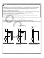
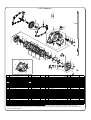
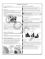
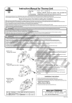
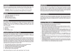
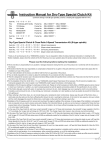
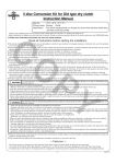
Dry-Type Clutch Kit Instruction Manual
Item No.
02−02−0112 for stock transmission
02−02−0132 for our 6-speed transmission
CO
Applicable models and Frame No.
AC16-1000001∼
Ape50
AC16-1600001∼
Ape50 (FI)
AC18-1000001∼
Ape50 (FI Type D)
HC07-1000001∼
Ape100
HC13-1000001∼
Ape100 Type D
AD14-1000001∼
XR50 Motard
HD13-1000001∼
XR100 Motard
・Thank you for purchasing one of our products. Please strictly follow the following instructions in installing and using the products.
・Before fitting the products, please be sure to check the contents of the kit. Should you have any questions about the products, please kindly contact your
dealer.
◎ Please note that, in some cases, the illustrations and photos may vary from the actual hardware.
Please read following instructions before installation
◎ We do not take any responsibility for any accident or damage whatsoever arising from the use of the products not in conformity with the instructions in
the manual.
◎ We shall be held free from any kind of warranty whatsoever of products other than this product if the glitch takes place on the other products than
this one after the installation and use of this product.
◎ You are kindly requested not to contact us about the combination of our products with other manufacturers'.
◎ This product is designed for exclusive use in the above-mentioned types of motorcycles and frame numbers only. Please take note that these products
cannot be mounted on other types of motorcycles.
◎ These products are not designed for use in combination with other manufacturers’ transmissions.
◎Installation of this product requires engine removal and mounting, crank case disassembly, and other work. Please prepare and strictly follow HONDA genuine parts service manual for your vehicle. In addtion, you need to prepare gaskets and packings suitable for the specifications of your vehicle.
◎ If the friction disk gets covered with water, for example when running in the rain, clutch slipping may occur causing the clutch to be nonfunctional.
If possible, avoid running in the rain, or when it is inevitable, try to skirt a puddle as much as possible to prevent the friction disc from getting wet.
◎ If a friction disc and some other parts around it get wet, the clutch will not work. Always wipe the water off the friction disc, a clutch plate and other parts
, and dry them sufficiently after riding your vehicle in the rain, or washing. In the damp climate, keep your vehicle with the clutch disengaged to prevent
the friction disc, the clutch plate and other parts from sticking each other.
◎ In case you use an oil cooler, you can take out an oil line from the cylinder side or right crank case cover by using our bore-up cylinder (※) or a seprately-sold oil cooler adapter (09-07-053 / 054 / 055).
※ The bore-up cylinder should be limited to the one with a hole on the right surface for getting the oil line out.
◎ Please be informed that, mainly because of improvement in performance, design changes, and cost increase,
the product specifications and prices are subject to change without prior notice.
◎ We shall be held free from any kind of warranty whatsoever of products other than this product if the glitch
takes place on the other products than this one after the installation and use of this product.
◎ This manual should be retained for future reference.
PY
∼ Features ∼
・We have changed the clutch outer from the conventional aluminum-forged one to the aluminum die-cast one, thus increasing the durability and strength.
・As the clutch section is located outside, it has an excellent cooling effect. Moreover, since there is no oil resistance, it improves the clutch disengagement.
In addition, this dry-type clutch restrains oil from deteriorating caused by the wear of the clutch disk or heat, and reduces adverse effect on the engine.
・We increased the number of the clutch friction discs to five, which accordingly can respond to a high-power engine. In addition, by casting cast iron on
the faces of discs which hit both the clutch center and the clutch pressure plate, we succeeded in doing without a clutch plate which has traditionally
been regarded as necessary and successfully reduced the weight.
In addition, by compounding Kevlar fiber in the clutch friction discs, we have made the discs more durable than the conventional ones.
The increased friction factor has brought about the decrease in the slipping, judders and noises generated when engaging the clutch.
・By embedding dampers to the primary driven gear, the shock or jolt at the time of engaging the clutch can be reduced.
・We adopted a paper-type oil filter to improve the filtration property of engine oil, and created an oil window to check the remaining oil amount.
The following show the envisioned possibility of injuries to human bodies or property damage as a result of disregarding the following
CAUTION cautions.
・Please try to ride a motorcycle at legal speed on the public road, abiding by the law.
・Work only when the engine and the muffler are cool. (Otherwise, you will burn yourself.)
・Prepare right tools for the work, and do the work in the proper and right way.
(Otherwise, improper work could cause breakage of parts or injuries to yourself.)
・Always use a torque wrench to screw bolts and nuts tight and securely to the specified torque.
(Improper torque could cause these parts to get damaged or fall off.)
・As some products and frames have sharp-pointed or protruding portions, please work with your hands protected.
(Otherwise, you will suffer injuries.)
・Before riding, always check every section for slack in parts like screws. If you find slack ones, screw them securely up to the specified torque. (Or improper torque may cause parts to come off.)
・Please replace gaskets and packings with new ones. Check carefully those parts to be reused, and in case wear or damage is detected, always replace them with new ones.
-1-
Aug./28/’
12
WARNING
The following show the envisioned possibility of human death or serious injuries to human bodies as a result of disregarding the
following cautions.
・Those who are technically unskilled or inexperienced are required not to do the work.
(Improper installation could lead to a driver falling down or accidents as a result of parts breakage.)
・Rotating parts in the dry clutch, such as a clutch outer, are touchable through an opening. Please never look into it or touch it when the engine is running. Moreover, be dressed to protect your legs when riding so you do not get your clothes caught in the rotating parts of the clutch.
(Other wise, falling accidents and human injuries may occur.)
・Always drive the engine in a well-ventilated place, and do not switch the engine on in an airtight place.
(Otherwise, you will suffer from carbon monoxide poisoning. )
・When you notice something abnormal with your motorcycle while riding down a road, stop riding immediately and park your motorcyle in a safe place. (Otherwise, the abnormaility could lead to an accident.)
・Before doing work, place the motorcycle on level ground to stablize the position of your motorcycle for safety's sake.
(Otherwise, your motorcycle could fall down and injure you while you are working.)
・Check or perform maintenance of parts correctly according to the procedures in the instruction manual or a service manual.
(Improper checking or maintence could lead to an accident.)
・If you find damaged parts when checking and performing maintenance, do not use these parts any longer, and replace them with new ones.
(The continued use of these damaged parts as they are could lead to an accident.)
CO
∼ About Oil Lines ∼
о In the case of Ape50 and XR50 Motard, all the engine oil is provided to the cylinder head and the crankshaft via oil filter.
оAn oil line in the crankcase of Ape100, Ape100 Type D and XR100 Motard differs in shape from the one in Ape50 and XR50 Motard. However, by attaching
the provided rubber separator onto the first three types of motorcycles, all the engine oil can be arranged to flow through the oil filter to the cylinder head
and crankshaft just like the latter two types of motorcycles.
To cylinder head
PY
Oil Line Diagram
To cylinder head
To cylinder head
Oil filter
Oil filter
Rubber separator
(supplied in the Kit)
Oil
pump
Oil
pump
Oil
pump
To crank shaft
Crankcase
Flow of engine oil
Right crankcase cover
In the case of Ape50 and XR50 Motard
To crank shaft
Crankcase
Right crankcase cover
To crank shaft
Crankcase
Right crankcase cover
In the case of Ape100,Ape100 TypeD,
In the case of stock Ape50 / 100,
and XR100 Motard
and stock XR50 / 100 Motard
-2-
Aug./28/’
12
∼ Kit Contents ∼
4
45
5
CO
6
42
49
3
33
43
1
35
34
7
25
STD
10
26
11
27
28
23
12
8
9
14 15
13
46
47
47
48
47
47
46
Parts Name
Qty
Repair part Item No.
1
Right crankcase cover COMP.
1
11331-KRL-T00C
2
Clutch cover COMP.
1
11332-GEY-T00C
3
Right crankcase cover gasket
1
00-01-0097
4
Crankcase gasket
1
00-01-0112
5
19
20
44
Main shaft (for stock transmission) 12T
Main shaft (for TAKEGAWA' 6-speed transmission) 14T
1
23212-GEY-T00
21
18
23 24
2
22
32
47
No.
PY
36
16
17
47
37
38
30 29
40
41
39
31
Parts Name
23
in packs of
No.
1
26
Oil filter
Qty
1
00-02-0027
Repair part Item No.
in packs of
1
1
27
O-ring
1
00-02-0040
1
1
28
Oil filter cover
1
15411-GEY-T00
1
1
29
Plain washer, 10 mm
1
00-00-0151
10
1
30
Arm spring
1
00-02-0112
1
23213-GCR-T00
1
31
Flange bolt, 6x18
1
00-00-0023
2
00-02-0106
00-02-0107
1
1
6
7
Primary driven gear assembly. (71T)
Dowel pin, 8x14
1
2
23100-GEY-T00A
00-01-0317
1
2
32
33
Clutch release arm
Complete set of clutch cable
1
1
8
Clutch outer
1
23101-165-T00
1
34
O-ring
1
9
Flat head screw, 6x15
6
00-00-0031
5
35
Hole cap
1
12361-GEF-T00
10
Set ring, 17 mm
1
00-02-0128
1
36
Complete set of oil pot
1
00-02-0031
1SET
11
Clutch pressure plate
1
22350-181-T10
1
37
Oil seal, 60x80x8
1
00-02-0044
1
12
Clutch plate
4
00-02-0029
1
38
Oil seal, 18x29x7
1
020-01-0017
1
13
Clutch friction disk
5
02-02-0003
5
39
Clutch release pinion
1
00-02-0033
1
14
Clutch friction disk, B
1
00-02-0202
1
40
Oil seal, 10x17x5
1
00-02-0006
1
15
Judder spring
1
00-02-0203
1
41
Flat-head screw, 4x10
1
00-00-0190
6
16
Judder spring seat
1
22125-GEF-T10
1
42
Radial ball bearing, 6903
1
BG-000-0001
1
17
18
Clutch center
External circlip
1
1
22120-GEF-T10
00-02-0005
1
5
43
44
Oil seal, 17x32x7
Shield bearing
1
1
00-02-0004
00-00-0026
1
1
19
Clutch spring
4
22401-181-T00
1
45
Right rear engine hanger collar
1
50135-GEY-T10
1
20
Clutch lifter plate COMP.
1
22360-GEY-T00
1
46
Socket cap screw, 6x40
2
00-00-0137
4
21
Flange hex' bolt, 6x22
4
00-02-0098
4
47
Socket cap screw, 6x80
6
00-00-0351
2
22
Clutch release rack
1
00-02-0039
1
48
Socket cap screw, 6x100
1
00-00-0475
1
23
Socket cap screw, 6x15
6
00-00-0042
10
49
Rubber separator
1
00-02-0114
1
24
Clutch cable receiver
1
22839-181-T00
1
25
Oil filter spring
1
15413-181-T00
1
Tool Hex' wrench, 5mm
1
1
※ Please note that in ordering repair parts, be sure to quote the Repair Part Item No. Otherwise, we may not be able to accept your orders.
There are some parts, however, for which we are not in a position to accept your order in just the quantity to be used. In this case, please take
them in the quantity packed.
-3-
Aug./28/’
12
∼ Installation Procedure ∼
○ Check the contents of the kit.
○ Place and stabilize the vehicle firmly with a maintenance stand
or the like.
CO
(Transmission)
1. Remove the engine referring to HONDA genuine parts service manual
(hereinafter referred to as Service Manual).
2. Place the removed engine on a working table to stabilize it, and referring
to the Service Manual, disassemble the crankcase and take out the transmission.
3. To prevent axial direction from getting out of place, punch marked six places, or six places around bearings inside the main shaft of the right
crankcase (see picture below) with a center punch. (Punch diagonally
six places about 2 mm outside outer circumference of the bearings.)
(Right Crankcase Cover Installation)
1. Degrease the mating surface of the case, and fix kit’s two dowel pins and the right crankcase cover gasket to the crankcase.
2. Apply grease to the lip of each oil seal in the crankcase cover set, and
put in the case cover straight along the main shaft with care not to damage the oil seals. Then, temporarily fix it onto the crankcase with a
cap screw from the center to the outside diagonally to the specified torque.
Caution: Apply the specified torque.
Torque: 10 N・m (1.0 kgf・m)
※ Fit the case with enough care since the oil seals of the right crankcase
cover set sometimes get(s) turned up.
(Clutch Installation)
1. Attach the clutch outer to the main shaft, and temporarily tighten it with
6x15 mm flat-head screws. Then tighten them fully diagonally to the specified torque.
Caution: Apply the specified torque.
PY
Torque: 10 N・m (1.0 kgf・m)
4. Replace the stock main shaft in the transmission with a kit’s dry-type one.
※Be careful about the directions of each gear when mounting the main
shaft.
5. Put the transmission inside the crankcases, replace the crankcase gasket with a new one, and fit crankcases together to screw them.
6. Reinstall the parts which were detatched in disassemblying the
crankcase, following strictly the instructions and procedures in the
Service Manual.
At this point, leave the transmission main shaft with no parts attached to
it.
2. Pass a stock spline washer B through the main shaft first, and then a kit’s 17 mm set ring.
3.Into the clutch center, install the clutch friction disk, clutch plate, clutch friction disk B, judder spring seat and, judder spring as shown in the figure below. And attach the clutch plate and clutch disk alternately.
※ Be careful about the direction of the spring when installing it.
(Install the spring in the direction edged portion of the spring placed the
(Primary Driven Gear Installation)
Clutch plate
Judder spring seat, as shown in the fig. below.)
Clutch friction disk
Clutch friction disk B
Clutch plate
Apply engine oil to the tooth face of the primary driven gear assembly Clutch center
and the ball bearings, and grease to the oil seal, and insert the gear into
the main shaft.
※Peel the adhesive tape on the primary driven gear assembly, wipe off the tape mark with thinner or the like, and then apply grease thinly.
(Installation of rubber separator)
In the case of Ape100, Ape100 Type D or XR100 Motard
As shown in the photo, attach the rubber separator onto the oil line groove on the right side crankcase with the TAKEGAWA logo being visible and its protrusion being right in the dent of the case.
※ Install the rubber separator without using a hammer or the like.
※ First attach the clutch cover gaskets to the crankcase.
And check that the arrowed hole is not blocked up by the rubber
separator. And lastly attach the clutch cover.
Install the rubber
separator with
the TAKEGAWA
logo being
visible.
Make sure that this
hole is not blocked up.
Judder spring
Judder spring seat
※Since remaining oil on the clutch plates will cause slipping, degrease the
oil finely.
※ Check that the clutch center and the clutch pressure plate fit in each other exactly.
4. Holding the boss of a clutch pressure plate, align the protrusions of the
clutch friction disk with the grooves of the clutch outer. At the same time,
align the clutch center with the spline of the main shaft, and insert it.
5. Attach a kit’s external circlip to the grooves in the main shaft. Make sure
that the angle of the circlip faces outside.
※ Do not expand the external circlip more than necessary.
※ If the external circlip does not easily fit into the grooves, fit it while pulling the main shaft with a needle nose plier or the like.
6. Fix the clutch spring to the boss of the clutch pressure plate.
Install the
separator with
its protrusion
being right in the
dent of the case.
-4-
Aug./28/’
12
7. Attach the 6x22 flange hex bolts to the clutch lifter plate with its bearings facing outside. Tighten them as hard as possible by hand.
Pull the clutch lifter plate toward you and see if there is a clearance between the friction discs. If there is a clearance, this shows that the
clutch center and the clutch pressure plate got out of place each other. So, turn the clutch lifter plate to the right or left a little until they
fit each other. After making sure they fit rightly, fix and tighten the CO
6x22 flange hex bolts diagonally in incremental steps while pulling the
clutch lifter plate toward you. Finally, tighten them to the specified torque.
Caution: Apply the specified torque.
Torque: 12 N・m (1.2 kgf・m)
※ In working, be careful not to let the clutch springs get out of position.
(Clutch Cable Installation)
1. Referring to the Service Manual, reinstall the parts in the specified order
which were detached when disassemblying the crankcase.
Then mount the engine to the frame.
※Before mounting the engine, replace the standard right rear engine hanger collar (clutch cable guide) with its counterpart in the kit.
2. Attach the clutch cable receiver to the clutch cover set with the 6x15 mm
socket cap screw(s), and tighten the screws to the specified torque.
※ Apply grease to the clutch release rack.
4. Attach the clutch cable end to the clutch lever.
5.Connect the cable to the clutch cable without pulling it forcibly.
6. Apply a little grease to the clutch cable end, and put the clutch release arm.
※ Fix the arm so its notch faces the back of the vehicle.
7. Screw the adjuster of the clutch cable into the cable reciever to the end.
8. Stretching the inners of the clutch arm spring and the clutch cable, fix the release arm to the release pinion. Then fix them by tightening the 6x18 mm flange bolt(s) to the specified torque.
Caution: Apply the specified torque.
Torque: 10 N・m (1.0 kgf・m)
Caution: Apply the specified torque.
Torque: 10 N・m (1.0 kgf・m)
※Place the oil filter so that it sticks in the protrusion on the oil filter cover.
※Unless the oil filter spring is positioned on the inside of the protrusion from oil filter, there will be a gap between the oil filter cover and the right
crankcase cover.
※When replacing the oil filter, wipe off the oil on the O-ring’s working face
and the oil filter cover, and then apply grease to the O-ring thinly.
2. Reinstall the parts which were detached in demounting the engine, following the instructions in the service manual.
3. After checking that the drain bolt(s) is tightened to the specified torque
[torque: 21.5N.m (2.2 kgf.m)], put 1100cc of engine oil, attach the O-ring
to the hole cap, and tighten it to the specified torque.
Caution: Apply the specified torque.
Torque: 12 N・m (1.2 kgf・m)
※ Apply a little engine oil to hole cap’s O-ring.
※In case you do not disassemble the crankcase at the time of an oil change, put 900 cc of engine oil. And put 1,000 cc of engine oil when changing the oil filter.
PY
3. After making sure that there is the clutch release rack inside the clutch
cover set, fix the clutch cable firmly to the right crankcase cover, and fix
it by tightening 6x15 mm socket cap screw(s) temporarily. Then, tighten
up the screw(s) to the specified torque.
Caution: Apply the specified torque.
Torque: 10 N・m (1.0 kgf・m)
(Oil Filter Installation)
1. Put the oil filter spring inside the right crankcase cover so that it should
fit in the boss. Also attach the oil filter, and then fix the oil filter cover by
screwing 6x15 mm cap screw(s) to the specified torque.
4. Detach the spark plug, and push down the
kick-starter a few times so the engine oil gets
circulated all around the engine. And then, put
back the spark plug where it was.
Only as a guide via
oil window
(Checking after Installation)
1. With the engine turned off, shift the transmission to first speed, and hold
the clutch lever. Then, check that the rear wheel rotates when you move the mahine, and that the rear wheel does not rotate when you have released the clutch lever.
2. Shift the transmission into NEUTRAL, and start the engine. Then check
each section for oil leak. If nothing is wrong, do a test run at slow speed
in a safe place to check the clutch operation.
※ Install the release arm by aligning the serrations with each other.
Otherwise, the release arm will be broken and unusable.
9. Adjust free play at the adjuster part of the clutch cable reciever, tighten
the lock nut(s) to the specified torque, and put on the rubber caps on the
clutch cable adjuster.
※ Adjust the free play at the tip of the clutch lever to be 10 to 20 mm.
Co.,Ltd.
3-5-16 Nishikiorihigashi Tondabayashi Osaka Japan
TEL : 81-721-25-1357 FAX : 81-721-24-5059
URL : http://www.takegawa.co.jp
-5-
Aug./28/’
12