1
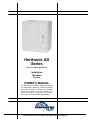
Herrtronic AD
Series
Electronic Steam Humidifiers
Installation
Operation
Service
OWNER’S MANUAL
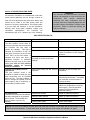
The AD Series Humidifiers represent the latest
in humidification technology. Please read these
instructions carefully for trouble free operation
and to get the most out of your purchase. For
further information concerning this product,
contact your local Herrmidifier representative.
Herrtronic AD Series Installation, Operation and Service Manual
TABLE OF CONTENTS
SECTION I WARRANTY
Page
Warranty…………………………………………………………………………………………………………………………………3
SECTION II UNIT OPERATION
Basic Operation ………...…………..…………………………………………………………………………………………………4
Key Features……………………………………………………………………………………………………………………………5
Engineering and Application…………………...……………………………………………………………………………………6
SECTION III INSTALLATION INSTRUCTIONS
Mounting…………………………..……………………………………………………………………………………………………7
Plumbing………………………………………………………………………………………………………………………………..7
Supply Power……..……………………………………………………………………………………………………………………8
Steam Distribution………………………………………………………………………………………………………………….8-9
Control Circuit Connections… ………..……………………………………………………………………………………..…...10
SECTION IV OPERATING INSTRUCTIONS
Start-Up Instructions…………………………………………………………………………………………………….………..…11
Check List ..…………………………………………………………………………………………………………………………..12
Maintenance…………………………………………………………………………………………………………………………..13
SECTION V TROUBLESHOOTING GUIDE
Trouble Shooting Unit Detected Faults…………..………………………………………………………………………………14
Trouble Shooting Non-Fault Activated Problems……..……………………………………………………………………15-16
Circuit Board Diagram …………………………………………………………………………………………………………..….17
Exploded View and Part Lists.…… …… ………………………………………….…………………………………………18-22
Unit Wiring Diagram……………… .……..………………………………………………………………………………………...23
4
Herrtronic AD Series Installation, Operation and Service Manual
SECTION I WARRANTY
1. TRION, Inc. warrants to the buyer or any user during
the duration of the Warranty that the humidifier
described in this manual will be free from defects of
material and workmanship for a period of two (2) years
from the date of shipment.
5. This Warranty does not cover field labor for
repairs to this humidifier or any special, indirect or
consequential damages. Some states do not allow
the exclusion or limitation of incidental or consequential
damages, so the above limitation may not apply to you.
2. For this Warranty to be effective, this humidifier must
be installed, operated and maintained in accordance
with the Installation Instructions, Operations and
Service Manual(s) supplied with the humidifier.
6. If, after a reasonable number of attempts to do so, the
TRION, Inc. is unable to remedy any defects or
malfunctions in this humidifier, then the user may elect
either a replacement of such product or part which may
be defective without charge or a refund at the buyer's
original purchase price.
3. In the event of a defect or malfunction in this product
during the Warranty Period, user may return the
humidifier to the Herrmidifier Factory Repair
Department for complete reconditioning without charge
to the user for parts or labor. Incidental expenses such
as costs of transporting the humidifier to the Factory
Repair Department shall be borne by the user. Upon
completion of the reconditioning, the humidifier will be
returned F.O.B. Destination (in the continental USA) at
no cost to the user.
7. This Warranty gives you specific legal rights, and you
may also have other rights which vary from state to
state.
4. Each of the Herrtronic series of steam generating
humidifiers contains a plastic steam generating cylinder
which is to be considered a routinely disposable part to
be changed at regular maintenance intervals at the
user's expense. This steam generating cylinder is not
covered by this Warranty. If, after the first installation of
your Herrtronic humidifier, you feel the steam generating
cylinder is not operating normally, you should return the
cylinder to Trion, Inc. with an explanation of the problem.
However, in the continuing operation of this humidifier,
replacements of this part are your responsibility as part
of routine maintenance.
Herrtronic AD Series Installation, Operation and Service Manual
SECTION II UNIT OPERATION
Basic Operation
Controlled humidification requires a very precise control
system. The Herrtronic AD utilizes a solid state control to
monitor performance and maintain humidity. Further, the
Herrtronic AD evaluates the operation and alerts the
operator to problem conditions and prevents undesirable
operation.
1. Start-up: On initial start-up (prompted by the
humidistat), the fill valve opens allowing water to enter
the cylinder. When the water level rises to the
electrodes, current will flow and the water will begin
heating. As the water temperature rises, its conductivity
also increases, accelerating the rate of temperature
increase. When the output reaches the "capacity set
point”, the fill valve closes. The output capacity may
continue to rise slightly beyond the "capacity set point".
As the water boils, the water level falls with resulting
output reduction.
2. Normal Operation: Upon achieving "capacity set
point”, the system begins operation in a steady state
mode. Output capacity slowly decreases until the
elapsed "cycle time" opens the fill valve to replenish the
water level until the "capacity set point” output is
achieved. As the mineral concentration in the water
increases, the water conductivity also increases.
Accordingly, the rate of boiling increases. Eventually, the
rate of boiling reduces the output capacity below the
"low drain threshold" before the "cycle time" initiates the
fill cycle. At this point, the drain valve opens discarding
the mineral laden (highly conductive) water, replacing
with fresh water, that lowers the mineral concentration
until the system is restored to the steady state mode.
This steady state operating mode continues with small
increases in the water level to maintain output capacity
(exposing new electrode surface).
3. End-of-Cylinder Life: Steady state operation
continues with "fill and boil" and periodic drain cycles
with ever increasing water levels. Eventually, the water
level reaches the cylinder full electrode, representing the
maximum allowable water level. The system output
begins to decrease since there is no new electrode
surface to expose. If the system operates 45 minutes
continuously without achieving "capacity set point”, the
fault light will illuminate indicating an "end of cylinder life
fault." Cylinder replacement should occur to maintain
satisfactory humidity levels.
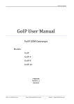
Herrtronic AD Series Installation, Operation and Service Manual
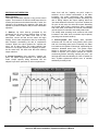
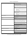
Conductivity*
Average Life**
Micromhos
Expectancy – Hrs.
(approx.)
(approx.)
70
100
135
170
255
510
765
1020
2000
2000
1900
1800
1300
800
650
500
Adjustable Set-point
*If the conductivity of your supply
water is less than 100 micromho,
Consult Herrmidifier for specific
circuit board adjustments.
**Your actual cylinder life may be
higher or lower depending on
the exact composition of your water
supply.
Faults
Capacity
•
Range=50-100%
•
Preset at 100%
Overcurrent
•
120% of Rated Current
•
System Shutdown
Low Drain Threshold
•
Range=50-100%
•
Preset; setting varies by unit
Cylinder Fill
•
Fill valve open for 45 minutes without achieving capacity setpoint
•
System Shutdown
Cycle Time
•
Range=60-300 Sec.
•
Preset; setting varies by unit
End of Cylinder Life
•
45 Minutes of operation without achieving capacity setpoint
•
System Shutdown
Herrtronic AD Series Installation, Operation and Service Manual
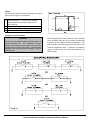
Engineering and Application
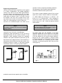
Herrtronic AD Series Steam Humidifiers can be applied
in a variety of applications. The simplest application
consists of an "AD" unit and an "RDU' (Room Distribution Unit). Steam is generated by the "AD" unit, transferred to the "RDU" unit, and distributed into the conditioned space. As shown in Figure 1, the "RDU" unit can
be mounted on the "AD" unit or remote from the "AD"
unit. Steam input is either into the bottom or rear of the
"RDU" unit. In this application, only the "RDU" unit
need be in the conditioned space. One "RDU" unit is
NOTE
A separate condensate return line must be installed
during installation.
required for up to 125 lbs./hr. of humidification.
Alternatively, steam generated by an "AD" unit can be
discharged directly into the system ductwork. In this
application, steam distributor pipe(s) are preferably
installed in the system ductwork at least three (3) feet
down steam of the supply air blower. There should be no
obstructions within the first three feet down steam of the
humidifier as shown in Figure 2. If the blower operates
intermittently ("Auto"), an air-proving switch should be
operation. Further, a high limit humidistat (located ten
feet downsteam of the humidifier steam distributor)
should be included for better system control.
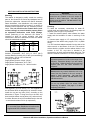
The number of steam distributor pipes will be at least
equal to the number of steam outlets on the humidifier i.e., ADM & ADS (up to 65 lbs./hr.) =1, ADS (65 - 125
lbs./hr.) =2. A "Y" connector (EST - 255) is available to
convert one steam outlet into two steam distributor
inputs. Figures 5, 6, and 7 reflect the spacing required
within the duct.
NOTE
The steam distributor pipes are inherently sloped to
return the condensate to the humidifier.
The steam piping from the humidifier to the steam
distributor should have an 8% slope up to the steam
distributor. Steam hose may be used up to a maximum
of 20 feet between the unit and the steam distributor.
Beyond 20 feet, system capacity is reduced unless
insulated copper pipe (I 1/2" ID) is used. If there are any
low spots between the humidifier and the steam
distributor, a condensate separator (EST-250) should be
used (Figure 8).
.
provided to assure blower operation prior to humidifier
Herrtronic AD Series Installation, Operation and Service Manual
SECTION III INSTALLATION INSTRUCTIONS
Mounting
The cabinet is designed to safely contain the working
parts of the Herrtronic AD Series and dissipate heat to
protect the electronics. Herrtronic AD Series electronic
steam humidifiers, room distribution unit, steam pipes,
and any accessories should be located in a manner to
facilitate routine inspection and any necessary maintenance. The unit should not be located above (such
as false ceilings) or around valuable property where
an equipment malfunction could cause damage.
Correct positioning of the Herrtronic AD Series is
important to allow for proper operation and easy
maintenance. Minimum clearances around the cabinet
should be maintained as shown:
UNIT
SERIES
Left
Right
Top
Bottom
CLEARANCES
ADM
5-30#
2”
15”
12”
10”
ADS
10-100#
2”
15”
12”
10”
Allowable Operating Conditions
Ambient Temperature: 40°F (4°C) to 120°F (50°C)
Ambient Relative Humidity: 0% to 90% (non-condensing)
Line Voltage: -15% to +10% of Nominal
Frequency: 50/60 HZ.
Supply Water Pressure: 20 psi- I 00 psi
Supply Water Temperature: 40°F- I 00°F
Supply Water Conductivity: 70- 1 000 micromho
WARNING!
Do not mount any controls inside the unit or tap
power from any location in the unit, except as
stated in these instructions. Do not place
objects near the cabinet. Do not attach to dry
wall without studs.
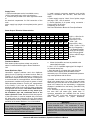
Plumbing
To make the necessary connections for water fill,
cylinder drain and cabinet drain, the following steps are
required: (refer to Figure 3 for locations)
1. Install an external shutoff valve between the water
supply and the humidifier for ease in servicing of the
unit.
2. Connect water supply to 1/2" compression fitting on
the bottom of the cabinet using copper, PVC, or plastic
tubing.
3. A 3/4" hose barb adapter extends from the side of the
drain reservoir on the bottom of the unit. This reservoir
collects both the cylinder and the cabinet drains in one
location. A 3/4" I.D. vinyl tube is included to be
connected to the drain reservoir and the drain line. The
drain line must be a minimum I" I.D. PVC or copper line.
NOTE
Inlet water pressure must be in the range of 20100 psig. Consult the factory if you are outside
of this range. Softened water may be used and
requires that the low drain threshold be
“adjusted.”
WARNING!
Do not mount any controls inside the unit or tap
power from any location in the unit, except as
stated in these instructions. Do not place
objects near the cabinet. Do not attach to dry
wall without studs.
Four lag bolts, (2) 5/16" and (2) 1/4", are supplied with
the AD Series which is designed to be secured to a wall.
Install the top two lag bolts (5/16") according to the
dimensions in Figure 3. Hang the unit on the wall, and
then install the bottom two lag bolts (1/4") and secure all
four bolts. Be sure the unit is mounted directly to the wall
- to wood studs at least 2" thick (or equivalent.)
WARNING!
Do not use plastic drain line unless “Drain
Tempering” is enabled. See page 11 for drain
tempering instructions.
NOTE
To mount the Room Distribution Unit refer to the
supplemental RDU Installation Instructions.
Herrtronic AD Series Installation, Operation and Service Manual
Supply Power
1. Insure that adequate service is available to carry
125% of rated amps level. (refer to chart below).
2. Terminals are provided in the lower right hand comer
of
the electrical compartment for field connection of the
main
power supply legs (single or three phase) and a ground
wire.
3. Install external overcurrent protection and provide
wiring in accordance with the NEC, state and local
codes.
4. Power supply must be "clean": free of spikes, surges
and sags: +10%, -15% of nominal.
5. Check tightness of all power wiring connection Factory wiring: 35-45 in-lbs.
Field wiring: 35-275 in-lbs.
See Power Distribution Blocks for Exact Specification
Steam Output / Electrical Characteristics
Lbs./Hr.
Kg./Hr.
Volts/Ph:
208/1
240/1
208/3
240/3
480/3
600/3
5
2.3
10
4.5
15
6.8
20
9.1
1.7
3.3
5.0
6.6
8.0
6.9
4.6
4.0
2.0
1.6
16.0
13.8
9.2
8.0
4.0
3.2
24.0
20.8
13.9
12.0
6.0
4.8
32.0
27.6
18.5
16.0
8.0
6.4
STEAM OUTPUT
25
30
40
11.4 13.6 18.2
INPUT KW
8.3 10.0 13.3
AMPS
40.0 48.1 64.1
34.7 41.7 55.6
23.1 27.8 37.0
20.0 24.1 32.1
10.0 12.0 16.0
8.0
9.6 12.8
Distribution Method
Each steam cylinder requires at least one outlet for
steam via a duct distributor pipe or Room Distribution
Unit.
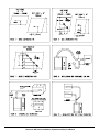
Steam Distributor Pipes
Herrmidifier supplies stainless steel duct distributor
pipe(s) for use in injecting pure steam into duct. Refer to
Figures 5, 6 or 7 for proper placement. A minimum of 3'
downstream clearance before any bends or obstructions
is recommended for most applications, however differing
psychrometric conditions may require a greater or lesser
steam absorption distance. Consult your representative
or the factory if you have any questions. The duct
distributor pipes have a built-in pitch to allow condensate
drainage back into the hose. The rubber steam hose is
of large diameter and is meant to carry steam up to
the distributor pipe and condensate back to the
steam cylinder for reuse. Because of this dual purpose
of the steam hose, it must be installed with a minimum
8% pitch back to the Herrtronic AD unit. Since steam
output losses are directly related to the distance from the
humidifier to the steam distributor, it is recommended:
NOTE
Steam holes are located within 2” of mounting plate
and closed end of distribution pipe. Use extreme
caution when applying to internally lined duct. Consult
factory if special hole locations are required.
50
22.7
60
27.2
80
36.3
100
45.4
16.7
20.0
26.6
33.3
80.1
69.4
46.3
40.1
20.0
16.0
55.5
48.1
24.0
19.2
74.0
64.2
32.1
25.6
92.6
80.2
40.1
32.1
125
56.8
• Kg/Hr = .454 x lbs./hr.
• Kw =.33 x lbs./hr.
• Amps (lPh) = Kw x
1000 ÷ Volt.
41.2
• Amps (3Ph) = Kw x
1000 ÷ (Volts x 1.732) •
Min Circuit Ampacity =
1.25 Rated Electrode
115.7
Amps (for each RDU,
add .5 Amps @ 208/
100.2
240v or add .25 Amps
50.1
@ 480v).
40.1
a. Mount the humidifier as close as possible to the
steam distribution pipe.
b. Use 1 1/2" I.D. insulated copper pipe if the length of
run exceeds twenty feet.
c. Keep the total run of copper pipe under thirty feet
since the actual capacity of the humidifier can be
reduced by up to 15% and the increased static pressure
may cause problems with the fill tee.
If possible, mount the steam distributor pipe to avoid low
spots in the steam hose. If you must, mount the steam
distributor pipe below the level of the humidifier, or if low
spots in the steam line are unavoidable, a condensate
separator is available from the factory (Part #EST-250)
(see Figure 8).
If it is necessary to split the output of one steam outlet
into more than one steam pipe, steam hose "Y"
connector assemblies are available from the factory
(Part #EST- 255). In this case, both ducts must be the
same static pressure for proper distribution.
WARNING!
Do not mount the standard steam distribution pipe in a
vertical downflow duct. The combination of static
pressure and velocity pressure may be more than the
cylinder and/or the fill tee can handle. A special steam
distributor must be ordered when installing in a vertical
downflow duct
Herrtronic AD Series Installation, Operation and Service Manual
Herrtronic AD Series Installation, Operation and Service Manual
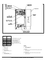
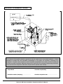
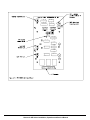
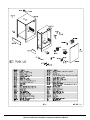
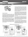
Wiring
All field wiring should be routed up through the bottom
panel (refer to Figure 11 for locations).
.
A Drain Connection – ¾” Hose. Use ¾” flexible
tube included to connect drain reservoir to 1”
Min. drain line.
B Knockout for Control Wiring
C Fill Connection – ½” Compression
D Knockout for Main Power Supply
Control Circuit Connections
WARNING!
Do not mount the standard steam distribution pipe in a
vertical downflow duct. The combination of static
pressure and velocity pressure may be more than the
cylinder and/or the fill tee can handle. A special steam
distributor must be ordered when installing in a vertical
downflow duct.
All external electrical control circuits are to be connected
to the humidifier using the 12 pole control terminal strip
located in the low voltage electrical compartment. The
terminal strip is accessed through the front door or the
electrical compartment door. A cable tie is provided to
secure all control wiring. All control wiring should be 18
AWG or larger.
Herrtronic AD Series Installation, Operation and Service Manual
SECTION IV OPERATING INSTRUCTIONS
Start-up Instructions
1. Check that the humidifier is properly mounted and
level.
2. Check that the fill water, unit drain, and cabinet drain
are properly connected.
3. Check that the correct voltage and amperage
services are supplied.
4. Check that the humidifier is specified to match your
controls and that all controls are wired properly.
5. Check that the steam distributor or room distribution
unit is properly installed and that the steam hose has
been properly routed without any kinks or flat spots.
Use a condensate separator (Herrmidifier P/N EST250) for any unavoidable low spots.
6. With power off, double check all electrical
connections and plumbing connections to insure that
they did not loosen during shipment.
7. With the manual drain switch in the “run” position,
and high limit and control humidistats at their lowest
setting, turn on the main disconnect. Contactors
should remain de-energized but the power lamp
should illuminate.
8. Turn the control and high limit humidistats up to their
highest setting. The contactor(s) should pull in.
9. After approximately a twenty second delay, the fill
solenoid should energize and water begins to fill the
humidifier to the preset amp level or cylinder full
condition, depending on the incoming water supply.
When starting up the unit, it is best to put an amp
clamp on the power leg that passes through the
torroid transformer. Insure that the humidifier fills to
"cylinder full" (approximately 1.5” from the top of the
cylinder), or that the amperage reaches the data
plate maximum and the fill solenoid turns “off”.
10. If after installing jumper wires on ADS unit, or if any
ADM unit fails to reach 75% of output, follow
instructions in Troubleshooting Section, item K to
quickly achieve 100% of output.
11. If plastic drain line is used or local codes require a
lower drain water temperature, drain tempering must
be enabled. To enable, place the diode supplied in
the accessory pack in to the open socket labeled
“DR18” on the P.C. board. Be sure the silver band
on the diode is properly oriented with the PCB
labeling. See page 16 (Figure 23) for the location of
CR18. The addition of this diode will energize the fill
solenoid whenever the drain solenoid is
automatically energized by the control board. The
fill solenoid will NOT be energized when using the
manual drain switch. Therefore, be sure to allow the
water in the tank to sufficiently cool prior to utilizing
the manual drain. Some adjustment of the fill
solenoid metering valve may be necessary to allow
proper drain rate and water temperature.
NOTE
The capacity of the humidifier can be reduced
up to 50% of the factory set maximum level by
adjusting the capacity adjustment potentiometer
(labeled R39) on the main circuit board.
NOTE
For ADS UNITS ONLY
If you have a humidifier that has two power
wires (some single phase units) or three power
wires (some three phase units), you will find
several jumper wires in your accessory pack.
On initial start-up, if the unit fills to cylinder full
and reaches less than 75% of its rated amp
draw, turn off the unit, disconnect the power
supply and install the jumper wires between
each power electrode and the unused electrode
next to it. (See page 13 for proper connection
procedure). Restart the humidifier following the
above instructions.
Herrtronic AD Series Installation, Operation and Service Manual
Herrtronic AD Humidifier Checklist
NOTE
The Herrtronic AD Humidifier checklist is provided to help the installer insure a successful installation. If further
assistance is needed from the Herrmidifier representative or the factory, the checklist is expected to be
completed. If a jobsite visit is required from the Herrmidifier representative or the factory, and the checklist has
not been accurately completed, additional charges will be required by the individual(s) representing Herrmidifier.
If the visit uncovers a component malfunction, the parts will be replaced under warranty.
_____________________________________________
Project Name
____________________________________________
Checklist completed by
_____________________________________________
Humidifier Installer (Company)
____________________________________________
Checklist completion date
Herrtronic AD Series Installation, Operation and Service Manual
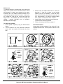
Maintenance
To maintain efficiency, the water level in the cylinder will
slowly move upwards, as the electrodes become coated
with minerals, to expose new electrode to the water.
Eventually all of the usable electrode surfaces will be
coated and the cylinder will be full of water. At this point,
the “cylinder full” light will turn on and the output will
begin to fall. This indicates the need to change the
cylinder – typically 500-2000 hours of operation,
depending on water supply.
To remove the cylinder
1. Drain cylinder completely using the Manual Drain
Switch.
2. Turn off power to the unit. Disconnect electrode
power wires and cylinder full electrode wire from
tank.
3. Remove tank and replace with new one. Be sure
that both “o” rings are in place on the cylinder
fill/drain neck prior to installation. Clean and check
both the fill and drain solenoids while servicing the
unit. Check strainer. If it is dirty or restricting water
flow – replace. Insert new fill valve / strainer.
4. Install cylinder in unit. Make sure that all electrical
connections are securely tightened.
5. Follow cold start-up instructions on page 11.
Extended Shutdown
Always drain cylinder completely if unit will be off for an
extended period of time. This will preserve the life of the
cylinder.
Herrtronic AD Series Installation, Operation and Service Manual
Section V TROUBLESHOOTING GUIDE
All Herrtronic Humidifiers are manufactured under strict
quality control guidelines and run through a series of
tests. All circuit adjustments are made at the factory and
should not be made in the field except under the
direction of a factory representative. The following table
is for your help and reference. If you still experience
difficulty after trying these remedies, contact your
Herrmidifier representative. The humidifier will
automatically shut off if it detects any of the following:
WARNING!
The Herrtronic AD Series Electronic Humidifier
cabinet was designed to house and shield the
components
from
outside
interference.
Absolutely NO other components may be
mounted inside or be electrically tapped into the
humidifier without Herrmidifier's express written
permission. Failure to heed this warning will
void your warranty.
UNIT DETECTED FAULTS:
Problem / Symptom
Overcurrent
The fault condition occurs when an
overcurrent situation has occurred and
the humidifier has shut down to
prevent any damage. This fault is
indicated by illumination of both the
“fault light” on the front of the unit and
L.E.D. CR17 on the circuit board. It
indicates that there has been a
significant reduction in resistance
between the main legs of the power
supply (both ADM and ADS) and the
humidifier should be serviced
before it is restarted.
Cylinder Full Condition / End of
Cylinder Life
This fault condition occurs it the
humidifier is unable to satisfy the amp
draw requirement over an extended
period of time. This fault indicates a
need to change the cylinder, that the
water supply is low in conductivity, or
that a foaming condition exists.
Probable Cause
Dead short between electrodes.
Reason - Correction
Replace the steam cylinder.
Restricted or blocked drain.
Clean and inspect drain system.
Restricted fill system
Clean and inspect the fill system.
Check for restriction or loss of supply
pressure.
Consult the factory for options.
Fill System Fault
This fault occurs when the fill solenoid
has been energized for an excessive
period of time. The humidifier has
been shutdown to prevent any
damage.
Incoming water conductivity is outside
the range of normal circuit board
settings.
Fault occurs within first few hours of
operation.
See start up note on jumper wire
installation.
Foaming condition exists.
Defective fill solenoid
Flush and fill that steam cylinder
several times and restart. If it persists,
you must filter or treat the water to
remove the foam.
Cylinder life is typically between 500 to
2000 hours, depending on incoming
water supply. (See unit operation
section for typical cylinder life
expectancy chart.)
Repair or replace as required.
Defective drain solenoid
Repair or replace as required.
Loss of or restricted water supply
Leaking drain system
Check fill system.
Check drain system.
End of Cylinder Life
NOTE: The three fault conditions outlined above will cause the humidifier to shut down and the service light on the
front of the unit to illuminate. To clear these faults, the main power must be turned “off” and back “on” again.
Herrtronic AD Series Installation, Operation and Service Manual
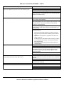
NON-FAULT ACTIVATED PROBLEMS:
Problem / Symptom
Water “foaming” inside cylinder energizes cylinder full light.
Main 24 volt fuses blow. “Fault” light comes on as soon as the
humidifier is switched on.
Main 24 VAC fuses blow after humidifier is turned on for about 15
seconds
Humidifier goes into fault shortly after start-up.
Main fuses blow when the drain valve activates.
Humidifier turned on, but will not operate
Unit turned on. Contactor is pulled in, but not water enters the
cylinder.
Reason - Correction
Check drain valve and insure that water drains freely. If necessary,
clean or replace coil or valve if defective.
Check water supply. If it is commercially softened, reconnect the unit
to a raw water supply, drain the cylinder, and either restart the unit OR
increase the drain threshold to 90%/ after draining the unit and restart.
If the unit is connected to a hot water line, reconnect to the cold water
supply.
Observe the fill tee. If water is going down the overflow and the water
level is low:
a. Check to insure that static pressure in the duct is not forcing
water down the overflow instead of allowing the water to
enter the cylinder.
b. Adjust the metering valve on the fill solenoid to regulate the
water flow to the cylinder.
Unit filling slower or at the same rate as it is boiling off causing overconcentration and foaming:
a. Fill rate must be increased. Open metering valve on fill
solenoid.
b. If “A” is not possible, get a water sample or water analysis
and consult factory
Check the wiring at 24 VAC fuses for a short or loose connection.
Check to make sure the capacity resistor is in main board socket R4.
Remove contactor coil from circuit and repeat. If 24 VAC fuses don’t
blow, replace contactor.
Remove fill solenoid from circuit. If fuses remain intact, replace the fill
solenoid coil.
Replace the main circuit board
Check amp draw to unit on initial start-up. If reading exceeds amp
rating by more than 20%, the low drain threshold, pot (Figure 23) on
the circuit board should be increased 2% on ADM’s and 5% on ADS’
to cause the unit to drain more frequently and hence reduce the
conductivity of the water in the tank. Manually drain humidifier and
restart.
Turn the capacity adjustment pot slightly counterclockwise. This will
provide a buffer between the unit normal amp maximum and the
overload amp level, a necessity with extremely conductive fill water.
Obtain a water analysis and consult the factory.
Check the fuses.
Open the drain valve and insure that it is clean and free of any
obstructing mineral deposits.
Remove drain solenoid from circuit. If fuses remain intact, replace the
drain solenoid coil.
Replace the main circuit board
Check fuses and replace if faulty
Insure that 24 VAC is reaching pole #9 connector J1 (Figure 23). If
not, check wiring.
Check external shutoff valves and open if closed.
Check that fill solenoid coil is receiving 24 VAC. If yes, replace the
solenoid.
Check for break in wiring
Replace the circuit board
Herrtronic AD Series Installation, Operation and Service Manual
NON-FAULT ACTIVATED PROBLEMS – CONT’D:
Problem / Symptom
Reason - Correction
Unit turned on. Unit cycles properly for short period of time. Then it
stops in the middle of a fill cycle and won’t reset until boiling stops.
Check cylinder full interface connections. Make sure terminal
Check cylinder connections (See Figure #11)
Check items in next troubleshooting tip concerning foaming.
Check amperage between cylinder full electrode and cylinder full
interface terminal #1. If it is greater than 7.0 mA AC, take a fill water
sample and consult the factory.
Water “foaming” inside the cylinder.
Check drain valve and insure that water drains freely. If necessary,
clean or replace valve if defective.
Check water supply. If it is commercially softened, either increase the
drain threshold (R18) to 92% or reconnect the unit to raw water. Drain
and restart the unit. If the unit is connected to a hot water line,
reconnect to the cold water line.
If steam line is hard copper, drain cylinder and test unit operation
disconnected from steam line to insure flux from solder joints is not
causing foaming.
Observe the fill tee(GT-120). If water is going down the overflow and
the water level is low:
•
Check to insure that static pressure in the duct is not forcing
water down the overflow instead of allowing water to enter the
cylinder.
•
Adjust the fill metering valve to regulate the water flow to the
cylinder. ( Figure 9)
•
Unit filling slower or at the same rate as it is boiling off, causing
over concentration and foaming. Fill rate must be increased.
Open metering valve.
•
If the fill valve is already fully open, get a water analysis and
consult the factory.
Check cylinder wiring (See Figure #11)
Check wiring of cylinder full interface.
If more than 1.9 mA AC is passing between the cylinder full electrode
and interface terminal #1, and when placing multimeter between
terminal #3 and ground yields approximately negative 11 VDC,
replace the interface.
Replace the circuit board.
Consult the factory after obtaining a water analysis
Use the “On-Off Drain” switch to drain the cylinder. Turn the capacity
adjustment pot(R39) on the main circuit board to 80% and restart the
humidifier.
Check the drain valve and clean or replace if necessary.
If the drain valve doesn’t come on before the service light illuminates,
replace the main circuit board.
Check location and setting of high limit humidistat
Check for loose connections
Fill tube out of fill tee
Steam cylinder out of drain cup
Cabinet drain backing up, kink in drain line
Cylinder fills and overflows
Unit turned on, fills to full amp draw, stops filling, and after a delay, the
circuit breaker trips and the service light comes on.
Unit cycle “on” and “off” rapidly
Cabinet leaks
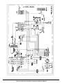
Herrtronic AD Series Installation, Operation and Service Manual
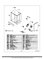
Herrtronic AD Series Installation, Operation and Service Manual
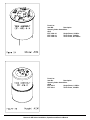
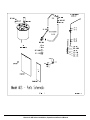
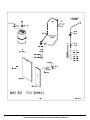
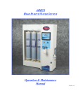
Parts List
Item NO.
Description
Steam Cylinder Assemblies:
ADS
EST-1002-4-1
Single Phase, 5 62#/hr.
EST-1002-6-1
Three Phase, 5 62#/hr.
EST-1002-6-2
Three Phase, 60-125#/hr.
Parts List
Item No.
Description
Steam Cylinder Assemblies:
ADM
EST-416-2
Single Phase, 5-15#/hr.
EST-416-3
Three Phase, 5-30#/hr.
Herrtronic AD Series Installation, Operation and Service Manual
Herrtronic AD Series Installation, Operation and Service Manual
Herrtronic AD Series Installation, Operation and Service Manual
Herrtronic AD Series Installation, Operation and Service Manual
Herrtronic AD Series Installation, Operation and Service Manual
Herrtronic AD Series Installation, Operation and Service Manual
Corporate Office: 101 McNeill Road • Sanford, NC 27330
Phone: 800-884-0002 • Fax: 919-777-6300 • www.herrmidifier.com• email:
[email protected]
Part No. 156573 • 2003, Trion, Inc. • Effective 5/03 • Subject to change without notice
Herrtronic AD Series Installation, Operation and Service Manual