1
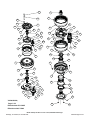
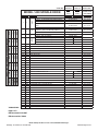
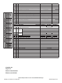
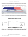
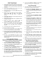
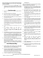
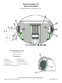
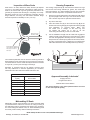
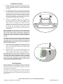
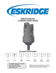
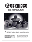
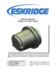
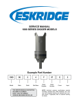
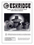
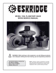
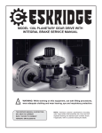
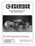
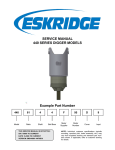
MODEL 1400 TRIPLE PLANETARY
SPINDLE DRIVE SERVICE MANUAL
!
WARNING: While working on this equipment, use safe lifting procedures,
wear adequate clothing and wear hearing, eye and respiratory protection.
THIS SERVICE MANUAL IS EFFECTIVE:
S/N: 74362 TO CURRENT
DATE: 10/01/2007 TO CURRENT
VERSION: SM1400LS3-AA
NOTE: Individual customer specifications (mounting
case, output shaft, brake assembly, etc.) may vary from
exploded drawing and standard part numbers shown.
If applicable, refer to customer drawing for details.
25C
6
12
25D
80C
80B
5A
53
80A
5C
16C
75B
5K
54
64A
75A
55G
5D
25A
55C
5E
5L
64B
55D
5G
5J
55H
5H
5B
55E
55F
5F
55A
55B
66
5G
12A
35A
55D
35C
35B
66
5E
5D
55E
16C
62
20C
20D
3
30
52
16C
30
14C
85
1
35D
4
14B
20B
7A
20A
7C
7D
14A
16B
7E
16A
7F
7G
2
7H
7F
7E
7E
7E
7D
30E
7B
X1400LS3-AA,
Page 1 of 3
X1400LS3-AA.1
30D
30C
DATE: 10/08/2007
Effective date 07/01/2007
Effective serial # 74362
Model 1400 Spindle Drive service manual, SM1400LS3-AA Page 1
Eskridge, Inc. Olathe, Ks. 913-782-1238
www.eskridgeinc.com
CORE UNIT:
MODEL 1400 SPINDLE DRIVE
Item # QTY.
Description
1400LS-41
26.48:1
4.96:1
5.33:1
41.41:1
7.76:1
5.33:1
EITHER RATIO
+ 3RD STAGE
Part Number
Part Number
Part Number
CODE A - FLANGED
60-004-3044
SEE 2-STAGE
60-004-3044Z
SEE 2-STAGE
60-004-3138
SEE 2-STAGE
60-004-3138Z
SEE 2-STAGE
(CUSTOM P/N)
SEE 2-STAGE
60-004-4052L
SEE 2-STAGE
(CUSTOM P/N)
SEE 2-STAGE
BASE
CODE A - FLANGED W/ BRG GREASE ZERK
1
1
CODE F - FLANGELESS
CODE F - FLANGELESS W/ BRG GREASE
ZERK
CODE CA or CF - CUSTOM
X1400LS3-AA
1
3
1
4
1
SPINDLE
CODE S1 - 12X 1-1/8 UNF ON 15.00 B.C.
CODE C1 - CUSTOM
COVER #1
INPUT
GEAR #1
5.33
5.33
5.33
5.33
5.33
5.33
Stg III
7.76
7.76
7.76
4.96
4.96
4.96
Stg II
7.59
5.87
3.95
7.59
5.87
3.95
Stg I
243
163
201
155
104
Unit
Model 1400 Shaft/Spindle Drive Ratio breakdown
314
2
2-STAGE+3STAGE CORE
1400LS-26
CODE D - SAE ‘D’ (4 BOLT)
60-004-1074
CODE E - SAE ‘E’ (4 BOLT)
60-004-1564
60-004-1934
CODE 9 (13T, 8/16 SPLINE)
60-004-1122
60-004-1142
CODE 5 (15T, 8/16 SPLINE)
PNNYA
60-004-1552
-----
CODE 8 (16T, 8/16 SPLINE)
60-004-1402
60-004-1492
SEE 2-STAGE
5
1
SEC CARR ASSY-5.33:1(1400)
60-005-2133
SEE 2-STAGE
5A
1
CARRIER SEC; 4-PLANET
60-004-1774
SEE 2-STAGE
5B
4
PLANET GEAR; SEC
60-004-1232
SEE 2-STAGE
5C
4
PLANET SHAFT; SEC
60-004-1262
SEE 2-STAGE
5D
8
CONE; SEC. PLNT
01-102-0210
SEE 2-STAGE
5E
8
CUP; SEC.PLNT
5F
4
RETAINING RING; PLANET SHAFT
01-160-0490
SEE 2-STAGE
5G
8
RETAINING RING; PLANET BORE
01-160-0500
SEE 2-STAGE
5H
8
WASHER; SEC
60-004-1291
SEE 2-STAGE
5J
8
SHIM; SEC. PLNT
60-004-1321
SEE 2-STAGE
5K
4
ROLL PIN; 1/4 x 1 3/8
01-153-0150
SEE 2-STAGE
5L
1
60-004-1352
SEE 2-STAGE
6
1
SUN GEAR -SECONDARY
60-004-1792
SEE 2-STAGE
7
1
PRIMARY CARRIER ASSY-1400
7A
1
SEE 2-STAGE
PLATE; SEC CARRIER RETAINER
60-005-2113
60-005-2123
SEE 2-STAGE
CARRIER; PRIMARY
60-004-1372
60-004-1722
SEE 2-STAGE
60-004-1862
60-004-1872
SEE 2-STAGE
7B
3
PLANET GEAR; PRIMARY
7C
3
PLANET SHAFT; PRIMARY
60-004-1272
SEE 2-STAGE
7D
6
THRUST WASHER; PRIMARY PLANET
60-004-1881
SEE 2-STAGE
7E
12
SPACER WASHER; PRI ROLLER; 4 PER SHAFT
60-004-1891
SEE 2-STAGE
7F
168
LOOSE ROLLER; 2 X 28 PER SHAFT
01-106-0050
SEE 2-STAGE
7G
3
ROLL PIN; 1/4 x 1 3/8
01-153-0150
SEE 2-STAGE
7H
3
RETAINING RING; PLANET BORE
01-160-0750
SEE 2-STAGE
12A
1
RING GEAR; SEC.
60-004-1243
SEE 2-STAGE
12B
1
RING GEAR; SIMPLE PRI
60-004-1193
SEE 2-STAGE
14A
2
THRUST RACE; PRI CARR
01-112-0350
SEE 2-STAGE
14B
1
THRUST BRG; PRI CARR
01-112-0340
SEE 2-STAGE
14C
1
THRUST RACE; INPUT GEAR
01-112-0060
SEE 2-STAGE
16A
1
SEAL; METAL FACE
01-406-0010
SEE 2-STAGE
16B
1
SEAL-RUBBER/FACE
01-406-0020
SEE 2-STAGE
16C
3
O-RING; RING GEAR
01-402-0660
SEE 2-STAGE
20A
1
BRG CONE; OUTER
01-102-0190
SEE 2-STAGE
Page 2 of 3
Effective date 07/01/2007
Effective serial # 74362
Model 1400 Spindle Drive service manual, SM1400LS3-AA Page 2
Eskridge, Inc. Olathe, Ks. 913-782-1238
www.eskridgeinc.com
1
BRG CUP; OUTER
01-103-0190
SEE 2-STAGE
1
BRG CONE; INNER
01-102-0230
SEE 2-STAGE
20D
1
BRG CUP; INNER
01-103-0230
SEE 2-STAGE
25A
3
FLAT HD SOC C.S.; SEC CARR RET. (3/8-24X1 GR-8)
01-150-1590
SEE 2-STAGE
25C
20 HHCS (3/4-10 x 10.5 GRD 8)
01-150-1580
SEE 2-STAGE
25D
20 HARDWASHER; 3/4; 1.25 O.D.
01-166-0350
SEE 2-STAGE
30A
4/6 PIPE PLUG (3/4 NPT MAGNETIC)
01-207-0100
SEE 2-STAGE
30B
1
GR. FIT; STR.1/8 NPT (O.D. of spindle flange)
01-215-0010
SEE 2-STAGE
30C
1
PIPE PLUG; 1/8 NPT (face of spindle flange)
01-207-0030
SEE 2-STAGE
30D
1
PIPE PLUG; 1/4 NPT (face of spindle shaft)
01-207-0020
SEE 2-STAGE
(01-215-0040)
SEE 2-STAGE
5.33
5.33
5.33
5.33
5.33
Stg III
7.76
7.76
4.96
4.96
4.96
Stg II
5.87
3.95
7.59
5.87
3.95
Stg I
243
163
201
155
104
Unit
Model 1400 Shaft/Spindle Drive Ratio breakdown
30E
(1) GR. FIT; STR.; 1/4 NPT (‘Z’ OPTION)
35A
2
SHIM; OUTPUT SHAFT
60-004-1311
SEE 2-STAGE
35B
1
SPLIT RING (L-SEGMENT)
60-004-1482
SEE 2-STAGE
35C
1
LOCK RING
60-004-1472
SEE 2-STAGE
35D
1
RETAINING RING; INPUT HOI #5008-400
01-160-0510
SEE 2-STAGE
MODEL 440 THIRD STAGE
CORE UNIT:
3RD-STAGE RATIO:
52
1
53
1
54A
1
54B
(1)
55
1
55A
1
1400-440-4
1400-440-5
1400-440-7
3.95
5.87
7.59
60-004-1902
SPLINED ADAPTOR SHAFT
COVER
#2
5.33
7.76
7.59
314
20B
20C
SAE ‘C’ 2 BOLT AND 4 BOLT
42-004-2012
SAE ‘D’ 4 BOLT
42-004-2022
SAE ‘E’ 4 BOLT
42-004-2032
42-004-1152
42-004-1162
42-005-0101
42-005-0111
42-005-0121
CARRIER - 3RD STAGE
42-004-1062
42-004-1072
42-004-1282
42-004-1102
42-004-1112
42-004-1272
INPUT
GEAR
INPUT GEAR 13 TOOTH, 8/16
FOR 14 TOOTH, 12/24, USE ADAPTER
CARRIER ASSY - THIRD STAGE
42-004-1172
98-005-1141
55B
3
PLANET GEAR - 3RD STAGE
55C
3
PLANET SHAFT - 3RD STAGE
55D
6
THRUST WASHER - 3RD STAGE PLANET
42-004-1362
55E
6
SPACER WASHER - 3RD STAGE ROLLER
42-004-1352
42-004-1342
55F
60
LOOSE ROLLER; 20 PER SHAFT
01-106-0040
55G
3
ROLL PIN; 3/16 X 1-3/4
01-153-0220
55H
1
62
1
RETAINING RING - ADAPTOR SHAFT
01-160-0690
RING GEAR - PRIMARY
42-004-1042
01-112-0400
64A
2
THRUST WASHER
64B
1
THRUST BEARING
01-112-0410
66
2
O-RING - RING GEAR
01-402-0840
75A
20 HEX HEAD CAPSCREW 5/8-11 X 4.5 GR 8
01-150-0870
75B
20 LOCKWASHER 5/8
01-166-0040
80
2
PLUG - COVER #2
01-208-0030
85
1
RETAINING RING - ADAPTOR SHAFT
01-160-0690
X1400LS3-AA
Page 3 of 3
Effective date 07/01/2007
Effective serial # 74362
Model 1400 Spindle Drive service manual, SM1400LS3-AA Page 3
Eskridge, Inc. Olathe, Ks. 913-782-1238
www.eskridgeinc.com
LUBRICATION & MAINTENANCE
Using the chart below, determine an appropriate lubricant viscosity. Use only EP (extreme pressure) or API GL-5 designated lubricants.
Change the lubricant after the first 50 hours of operation and at 500 hour intervals thereafter. The gear drive should be partially disassembled to inspect gears and bearings at 1000 hour intervals.
Recommended ambient and operating temperatures for conventional and synthetic gear lubricants
-50
-25
0
25
50
75
100
125
150
175
200
225
250 F
107
121 C
80W90 conventional
75W90 conventional
85W140 conventional
Min Ambient/operating temp
Max Operating temp
Max Ambient temp
75W90 synthetic
80W140 synthetic
-45
-32
-18
-4
10
24
38
52
66
79
93
Note: Ambient temperature is the air temperature measured in the immediate vicinity of the gearbox. A Gearbox exposed to the direct rays of
the sun or other radiant heat sources will operate at higher temperatures and therefore must be given special consideration. The max operating
temp must not be exceeded under any circumstances, regardless of ambient temperature.
ESKRIDGE MODEL 1400 OIL CAPACITIES
Operating Position
Oil Capacity
Single stage
Double stage
Horizontal Shaft
-
-
Vertical Shaft (Pinion Up)
-
Vertical Shaft (Pinion Down)
Oil Level
Triple stage
18 qts / 17 Liters
To horizontal centerline of
gear drive
-
27 qts / 25 Liters
To side port on gear drive
base
-
31 qts / 29 Liters
To midway on upper/
primary gear set
ESKRIDGE PART NUMBER INTERPRETATION
Note: All standard Eskridge Geardrives are issued a descriptive part number which includes information regarding
the Model, means of shaft retention, base style, shaft style, input mounting, input shaft size, overall ratio and various available options. For a detailed breakdown of this information, please refer to Eskridge product specification
sheets found at: http://www.eskridgeinc.com/geardrives/gearprodspecs.html
Model 1400 Spindle Drive service manual, SM1400LS3-AA Page 4
Eskridge, Inc. Olathe, Ks. 913-782-1238
www.eskridgeinc.com
Unit Teardown
1)
2)
Scribe a diagonal line across the outside of the unit from the top
cover (53) to the adapter cover (3), and to the base (1) before
disassembly to aid in the proper positioning of pieces during
reassembly.
Remove roll pins (55C Stg I, 7C Stg II) from planet shafts
(7C) using a 3/16” (Stg I) or 1/4” (Stg II) pin punch.
1)
Loose roller installation; if using bearing assemblies, replace bearings as needed and proceed to step 2:
Carrier Reassembly
Remove drain plugs (30A) and drain oil from unit. The oil will
drain out more quickly and completely if warm.
3)
Remove the twenty 5/8-11 capscrews (75B) securing the top
cover (53) to the unit.
4)
Remove the top cover (53), input thrust washer(s) ,
bearing(s) (64A, 64B), and Stage I input gear (54).
Inspect cover o-ring (66); discard if damaged or
deformed.
5)
Lift the stage I planet carrier assembly (55) including shaft
adapter (52) from the unit .
6)
Remove Stage I ring gear (62), inspect o-ring (66) and replace
if damaged or deformed.
7)
Remove the twenty 3/4-10 capscrews (25C)
lockwashers (25D) securing the ring adapter cover (3).
8)
5)
a)
Set planet washer (55D Stg I, 7D Stg II) on work
table with planet gear (55B Stg I, 7B Stg II) on top of
it. Center planet washer to planet gear as closely as
possible.
b)
Center planet shaft (55C Stg I, 7C Stg II) in planet
gear bearing bore.
c)
If used, place spacer washer (55E Stg I, 7E Stg II)
onto planet shaft (refer to exploded view to confirm
spacer positions).
d)
Begin placing rollers (55F Stg I, 7F Stg II) around
shaft (55C Stg I, 7C Stg II). There should be clearance for last roller to slide in. Be sure to install sixteen
(Stg I) or twenty (Stg II) rollers in each bearing row.
and
(If using multiple rows of rollers, repeat steps C and
D as necessary. Once complete, refer to exploded
view to confirm that any spacer washers (55E Stg I,
7E Stg II) are appropriately positioned.)
Remove the ring adapter cover (3), thrust race (14C),
Stage II sun gear (4) and thrust washers (14A, 14B) from
unit. Inspect cover o-ring (16C); discard if damaged or
deformed
e)
Place a washer (55D Stg I, 7D Stg II) over gear and
onto shaft.
9)
Lift the stage II planet carrier assembly (7) from the unit .
10)
Remove the Stage III sun gear (6).
f)
Carefully slide assembly off of table, holding planet
washers against planet gear.
11)
Remove the three 3/8-24 flat head capscrews (25A) securing
the carrier retaining plate (5L) to the output spindle (2).
g)
Slide planet shaft out of the assembly and slip assembly into carrier.
12)
Remove remaining ring gears (12B, 12A) and Stage III carrier assembly (5). Inspect gear to gear and gear to base Oring(s) (16C), discard and replace any damaged or deformed
O-rings.
h)
Align planet gear & bearing assembly inside
carrier and install planet shaft through entire
assembly.
13)
The unit is now disassembled into groups of parts.
The area(s) requiring repair should be identified by thorough
inspection of the individual components after they have been
cleaned and dried.
Carrier Assembly Teardown
Rotate planet gears (55B Stg I,7B Stg II, 5B, Stg III) to check for
abnormal noise or roughness in bearings. If further inspection
or replacement is required, proceed as follows.
1)
Drive roll pins (55G Stg I, 7C Stg II) completely into the planet
shafts or remove planet shaft retaining rings (5F Stg III)
2)
Slide planet shafts (55C Stg I, 7C Stg II, 5C Stg III) out of carrier (55A Stg I, 7A Stg II, 5A Stg III).
3)
Remove planet gears, washers (55D Stg I, 7D Stg II) and bearings (55E Stg I, 7F Stg II, 5D & 5E Stg III) from carrier.
4)
Inspect the planet gear, bearing bore and planet shaft (55C Stg
I, 7C Stg II, 5C Stg III) and bearings. Check for spalling, bruising or other damage and replace components as necessary.
Note: When using loose (uncaged) roller bearings, all rollers in
the corresponding planet gear should be replaced if any in the
set are found to be defective
2)
Planet shafts (55C Stg I, 7C Stg II, 5C Stg III) should
be installed with chamfered end of roll pin hole (Stg
I, II) or slot (Stg III) towards outside diameter of
carrier.
3)
Drive roll pin into the carrier hole (Stg I & II) and into planet
shaft or replace planet shaft retaining rings (Stg III) to retain parts. Repeat for remaining planet gears.
1)
Remove the output shaft lock ring (35C) using a heel bar
or puller; if using a heel bar, be sure not to pry against the
cage of the inner spindle bearing (20C). Remove the split
ring segments (35B) and shims (35A).
Base Subassembly Teardown
Caution: Since the shaft is no longer positively retained,
care should be taken to avoid injury. Care should also be
taken not to damage it while pressing through base.
2)
Place base (1) exterior side down, on a plate or table.
Press output shaft out bottom of base by applying a load
to internal end of spindle (2) until it passes through inner
spindle bearing cone (20C).
3)
A gear puller may be used to remove the outer bearing
cone (20A) from the spindle (2). If reusing old bearing
cone, do not pull on or damage roller cage.
Model 1400 Spindle Drive service manual, SM1400LS3-AA Page 5
Eskridge, Inc. Olathe, Ks. 913-782-1238
www.eskridgeinc.com
Note: Press bearing cone onto output spindle by pressing on
inner race only. DO NOT press on roller cage, as it may damage
the bearing assembly.
4)
Inspect inner and outer bearing cups (20D & 20B). If cups are
damaged they must be replaced, drive them out using a brass
drift and utilizing the bearing knock-out notches in the base
(1)
Base Reassembly
12A Stg III) pilots.
Caution: Use lifting device to prevent injury when handling
ring gears and other heavy components.
4)
Align gear teeth of Stage III ring gear (12A) with planet
gears (5B) and place on base, then align mounting holes
of ring gear with holes in base. Use the scribed line made
during disassembly for reference.
5)
With lubricated o-ring on pilot, place Stage II ring
gear (12) on base. Align mounting holes of ring
gear with holes in base, using the scribed line made
during disassembly for reference.
6)
Install the Stage III sun gear (6), then the Stage II carrier
assembly (7) aligning gear teeth of ring gear with those of
the planet gears
1)
Clean all foreign material from magnetic oil plugs located In
base (1).
2)
Place base exterior side up on work table.
3)
Apply a layer of lithium or general purpose bearing grease to
the roller contact surface of outer bearing cup (20B).
4)
Press outer bearing cone (20A) onto the spindle (2) until it
seats against the shoulder.
7)
Install Stage II sun gear (4), and stage II carrier thrustwashers (14A, 14B).
5)
Wipe the face of each half of the metal face seal (16A) using
a lint-free wipe. No particles of any kind are permissible on
the sealing surfaces. (Even a hair is sufficient to hold the seal
surfaces apart and cause a leak.) Apply a thin film of oil on
the entire seal face of one or both seals using a clean finger
or lint-free applicator. Oil must not contact any surfaces other
than the sealing faces. (See Pages 7-9 for seal inspection and
service procedures.)
8)
Install o-ring (16C) to ring adapter cover (3) and install
adapter cover to Stage II ring gear, aligning mounting holes
of cover with those in ring gears. Use the scribed line made
during disassembly for reference.
9)
Install, and torque the twenty 3/4-10 capscrews (25C) w/
lockwashers (25D) to retain adapter cover (3). The torque
for the capscrews is 380 ft.-lbs. dry or 280 ft.-lbs. lubricated
10)
Install o-ring on Stage I ring gear (62) and install ring gear
to adapter cover, aligning mounting holes of ring with
those in the adapter cover (3). Use the scribed line made
during disassembly for reference.
11)
Install the Stage I carrier assembly (55) with adapter shaft
(52) into the Stage I ring gear (62).
12)
Install the input gear (54).and thrust bearing set (64A,
64B) Refer to exploded view for details..
13)
Noting the scribed line made during disassembly, (with
lubricated o-ring in place) align and install the top cover
(53).
14)
Install and torque the twenty 5/8-11 hex-head
cap-screws (75A) with lockwashers (75B), retaining the top cover (53). The torque for the
cap-screws: 220 ft-lb dry, 170 ft-lb if the fasteners are lubricated.
15)
Using a splined shaft to drive the input gear (54) ensure
that the unit spins freely.
16)
Fill the unit to the proper level, as specified, with recommended gear oil (refer to chart, page 4) after unit is sealed
with brake and/or motor.
6)
Place the spindle (2) with the outer bearing cone into the
base.
7)
Flip
shaft/base
assembly,
and
apply
lithium
or
general
purpose
bearing
grease
to
roller
contact surface of the inner cup (20D), then press
inner bearing cone (20C) onto shaft until it seats against inner
bearing cup.
8)
9)
Proper spindle bearing preload will result in a rolling torque which
varies between 200 to 300 in-lb. The bearing preload should be
tailored to your application; a low-speed application may require a high pre-load, while high-speed applications usually
benefit from low pre-load. Adding shims (35A) will increase the
pre-load on the bearing set. Determine your pre-load requirement and install shims to obtain this pre-load.
Install the Load-N-Lock™ halves (35B) over the shims and into
the corresponding spindle groove. Then, install the lock ring
(35C) over the segments (35B).
All subassembly service or repairs should be complete at
this time. Continue to Unit Assembly to complete buildup
of unit.
Unit Reassembly
1)
Install the Stage III carrier assembly onto the output spindle
(2); align the splines of the carrier (5A) with the output spindle
splines and slide the carrier onto the output spindle.
2)
Install carrier retaining plate (5L) & secure using provided 3/824 Flathead capscrews (25A). If using retaining compound to
assist in screw retention, apply only a small amount to internal
threads. Use of excess thread retaining compound may cause
screws to be irremovable once the compound has cured.
3)
Lubricate o-rings (16C) and install on the ring gear (12B Stg II/,
The gear drive is now ready to use.
Model 1400 Spindle Drive service manual, SM1400LS3-AA Page 6
Eskridge, Inc. Olathe, Ks. 913-782-1238
www.eskridgeinc.com
Seal Assembly for
Duo-Cone Seals
Installation Instructions courtesy Caterpillar, Inc.
5
2
8
4
6
7
3
4
8
2
Seal Assembly Contents:
(2) Metal Seal Rings
2
(2) Rubber Toric Rings
Terminology:
1 - Seal Ring
6 - Seal Ring Face
2 - Rubber Toric
7 - Seal Ring Ramp
3 - Housing Retainer Lip
8 - Seal Ring Retaining Lip
4 - Housing Ramp
9 - Installation Tool (Optional)
5 - Seal Ring Housing (Base/Shaft)
7
1
Model 1400 Spindle Drive service manual, SM1400LS3-AA Page 7
Eskridge, Inc. Olathe, Ks. 913-782-1238
www.eskridgeinc.com
Inspection of Worn Seals
Housing Preparation
Seals wear in an axial, rather than radial, direction (as depicted
in Figure Y). The total thickness of the flange is usable wear material on the formed seal rings and good seal performance can
generally be expected until the flange is completely worn away.
Remaining service life can be estimated by measuring the ring
flange thickness, and using the chart below. Minimum flange
thickness required for reusability is 0.05” (1.27 mm).
The housing components (3, 4) that contact the rubber toric rings
must be free from foreign material (oil, grease, dirt, metal chips
dust or lint particles, etc.) before installing the seal. This should be
done with a lint-free wipe and a non-petroleum based solvent.
Measure Flange
Thickness Here
1)
Remove any foreign material from the rubber torics (2), ramps
(7) and lips (8) of both seal rings. This should also be done
with a lint-free wipe and non-petroleum based solvent.
2)
Dry with a clean wipe.
3)
Place the rubber toric (2) on the metal seal ring (6) at the
bottom of the seal ring ramp (7) and against the retaining lip (8)
(see illustration on previous page). Make sure
the rubber toric is straight on the seal ring and
not twisted. Be careful not to nick or cut the
torics during this assembly, as this can cause leaks.
4)
Put the installation tool (9) onto the metal seal ring (6) and
rubber toric (2). Lightly dampen the lower half of the rubber
toric with the appropriate assembly lubricant. Techniques to
dampen the toric include wiping with a lint-free towel, lubricating using a clean foam brush, or dipping into a container lined
with towels saturated in the assembly lubricant (as shown).
Development of a Wear
Lip in This Area Makes it
Necessary to Install a
New Seal
9
Figure Y
The measured parameter used to check the remaining seal life is
flange thickness, at the outer edge (once any wear lip is removed).
The measurement must be made carefully because the shoulder
is only 0.06” (1.52 mm) from the edge of the flange.
2
1
Estimates of expected seal life are difficult, because there
are many differences in machine applications, job conditions,
maintenance and other factors that affect seal service life.
Formed Seal Wear Chart
Seal Wear
Percent Worn
Approved Assembly Lubricants*
0.075 (1.91)
0
Houghto-Grind 60 CT
0.062 (1.59)
25
0.050 (1.27)
50
0.038 (0.95)
75
0.025 (0.64)
100
0.012 (0.32)
125
0.000 (0.00)
150
Flange Thickness
in (mm)
Isopropyl Alcohol
Quaker® Solvo Clean 68-RAH
*Do not use Stanosol or any other liquid that leaves an oil film
or does not evaporate quickly.
Mishandling Of Seals
Mishandling of seals during assembly can cause immediate leaks
or premature failure. Failure can occur due to cutting or tearing of
the elastomeric load ring, breakage of the sealing ring, contamination of the sealing face with dirt or lint, etc. When assembling metal
face seals, please carefully observe assembly instructions.
Model 1400 Spindle Drive service manual, SM1400LS3-AA Page 8
Eskridge, Inc. Olathe, Ks. 913-782-1238
www.eskridgeinc.com
Installation Process
1)
With the lower half of the rubber toric still wet, use the
installation tool (9) to position the seal ring (1) and the rubber toric (2) squarely against the housing retainer lip (3)
(as shown).
2)
For smaller diameter seals, use sudden and even pressure
to push the rubber toric under the retaining lip of the housing.
For larger diameter seals, which will not press in with sudden
and even pressure, it is acceptable to work the toric past the
retaining lip by starting on one side and tapping the opposite side of the installation tool with a rubber mallet until it is
engaged past the retaining lip of the housing.
3)
Check the assembled height (A) (see below) in
at least four places, 90º apart, using either a caliper, tool makers’ ruler or any other calibrated measuring device. The difference in height around the
ring must not be more than 0.04” (1 mm). If small
adjustments are necessary, do not push or pull directly on
the seal ring. Use the installation tool (9) to push down
and your fingers to pull up uniformly on the rubber toric
and seal ring.
NOTE: The rubber toric can twist if it is not completely wet
during installation or if there are burrs or fins on the retaining lip of the housing. Twists, misalignments and bulges of
the toric will result in seal failure. If correct installation is
not apparent, remove seal from the housing and repeat the
process.
The rubber toric must never slip on the ramps of either the
seal ring or the housing. To prevent slippage, allow adequate
evaporation time for the lubricant before proceeding with
further assembly. Once correctly in place, the rubber toric
must roll on the ramp only.
4)
Wipe each seal ring face (6) using a lint-free wipe. No particles of any kind are permissible on the sealing surfaces.
(Even a hair is sufficient to hold the seal surfaces apart
and cause a leak.)
5)
Apply a thin film of oil on the entire seal face (6) of one or
both seals using a clean finger or lint-free applicator. Oil
must not contact surfaces other than the sealing faces.
Dim A
NOTE: Mishandling of seals during assembly can cause
immediate leaks or premature failure. Failure can occur due
to curing or tearing of the elastromeric load ring, breakage
of the sealing ring, contamination of the sealing face with
dirt or lint, etc. When assembling metal face seals, please
carefully observe assembly instructions.
Final Assembly
While completing the final assembly of the unit, make sure
that both housings are in correct alignment and are concentric.
Slowly bring the two housings together. High impact can scratch
or break the seal components.
If the rubber toric slips at any location, it will twist, causing the
seal rings to cock. Any wobbling motion of the seal is an indication of cocked seals and can cause dirt to enter by pumping mud
past the torics.
Model 1400 Spindle Drive service manual, SM1400LS3-AA Page 9
Eskridge, Inc. Olathe, Ks. 913-782-1238
www.eskridgeinc.com