1
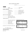
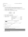
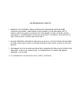
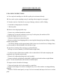
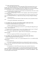
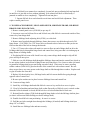
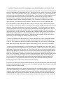
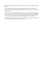
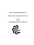
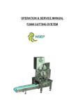
Operations
And
Maintenance Manual
MODEL 605/606 CENTRIFUGE
NORTH STAR ENGINEERED PRODUCTS
DIVISION OF GLASSLINE CORPORATION
PO Box 1141
Perrysburg, OH 43552
Phone: (419) 726-2645 ~ Fax: (419) 726-8583
Email: [email protected]
TEST & INSPECTION SHEET
SOLD TO ________________________
MACHINE
__________________ MODEL
________________ NSEP ORDER #
__________________ SERIAL NUMBER
________________ DATE
MOTOR & CONTROLS
__________________ INVERTER S/N
______________ CONTROL VOLTAGE
__________________ MOTOR VOLTAGE
______________ INCOMING POWER
__________________ MOTOR MFG
______________ MOTOR HORSEPOWER
__________________ MOTOR S/N
______________ MOTOR PULLEY SIZE
__________________ MOTOR RPM
______________ DRIVE BELT
DRIVE UNIT AND BASKET
__________________ UNIT PULLEY SIZE
__________________ BASKET RPM (MAXIMUM)
__________________ BASKET WEIGHT CAPACITY
TESTING RESULTS
Test Result Inspection Criteria
__________________ PROCEDURE NUMBER USED
__________________ STARTING AMPS
__________________ RUNNING AMPS
__________________ BRAKING TIME
__________________ INSPECTOR INITIALS
DO RESULTS FALL WITHIN SPECIFIED RANGES?
_______ YES = Machine Accepted
NORTH STAR ENGINEERED PRODUCTS
28905 GLENWOOD RD.
PERRYSBURG, OH 43551
REV D 8/06
Voltage
230 / 460
230 / 460
3 Phase Machine
Starting amps
Running amps
Braking time (sec)
Lower Limit Upper Limit
10 / 5
22 / 11
3 / 1.5
7 / 3.5
10
45
1 Phase Machine
Starting amps
Running amps
Braking time (sec)
Lower Limit Upper Limit
30
40
6
10
15
45
________NO = Machine Rejected
FORM Z-00860
TEST RESULTS #3
605, 606 & 805 CENTRIFUGES
SO# __________________________
CUSTOMER___________________
SERIAL# ______________________
1. CYCLE TEST MACHINE 15 TIMES WITH MAXIMUM LOAD OF BASKET
CAPACITY; INCLUSIVE SAFETY EVALUATION. CHECKED BY: _______
2. 5 OF THE 15 TEST CYCLES, FILL BASKET WITH WATER AND CHECK FOR SEAM
AND LID LEAKS. CHECKED BY: _________
3. 3 OF THE 15 TEST CYCLES RECORD CYCLE TIME.
_____ MINS. & ______ SEC.
_____ MINS. & ______ SEC.
_____ MINS. & ______ SEC.
4. WELD COSMETICS CHECKED BY: _________________
5. PAINT COSMETICS CHECKED BY: _________________
6. VIBRATION TEST
CONTROL BOX-SIDE _____________IN./SEC.
CONTROL BOX-TOP _____________ IN./SEC.
COIN BOX-SIDE _________________ IN./SEC.
TOTAL
__________ IN./SEC.
IF TOTAL IS GREATER THAN 1.5 = MACHINE REJECTED.
ACCEPTED _______________
REJECTED_________________
7. WEIGHT CAPACITY ETCHED ON BASKET _______________LBS.
8. COINAGE ____________ CENTS
9. SERVICE KEY AND BOX # ______________________________
10. COIN METER MFG. ____________________________________
11. COMMENTS ON MACHINE AND OPTIONS:
12. INSPECTOR’S NAME: _______________________________
FOUR IMPORTANT POINTS
1. REMOVE ALL SUPPORTS FROM (UNDER AND AROUND) BASKET BEFORE
STARTING MACHINE. WHEN REPLACING BASKET IN THE MACHINE, SET IT
GENTLY DOWN ON SHAFT AND ROTATE THE BASKET UNTIL IT DROPS DOWN
AND SEATS. AN IMPROPERLY INSTALLED BASKET CAN RESULT IN DAMAGE TO
THE CENTER POST AND/OR THE GYRO BALL.
2. DO NOT RESTRICT OR REDUCE DRAIN IN ANY WAY. DO NOT HOOK UP MACHINE
ON THE SAME DRAIN LINE AS OTHER EQUIPMENT BECAUSE A BACK WASH MAY
RESULT.
3. THE BRAKE ON YOUR NSEP MACHINE WILL REQUIRE SEVERAL ADJUSTMENTS IN
THE FIRST 30 DAYS OF OPERATION. IT IS IMPORTANT TO KEEP THE BRAKE
PROPERLY ADJUSTED.
4. IT IS ESSENTIAL TO MAINTAIN ALL SAFETY SYSTEMS.
PREPARATION FOR USE AND
INSTALLATION INSTRUCTIONS
UNPACKING INSTRUCTIONS:
A. Never top load centrifuge-use fork lift or pallet jack on bottom skid only.
B. Never stack or place anything on top of centrifuge when wrapped or unwrapped.
C. Examine exterior of machine for any sign of damage, and note on bill of lading.
1. Scratched or damaged parts of machine.
2. Broken pallet.
D. Remove outer shipping shrink wrap.
1. Remove any cardboard attached to machine.
2. Basket may be removed at this time as per step F at this point, (the machine will be
considerably lighter and easier to move).
3. Maneuver machine near desired location.
4. Remove machine from shipping pallet by removing bolts through legs and sliding or walking
machine off the pallet.
CAUTION: machine weighs approximately 800#, (do not use electrical boxes, lid hinge frame,
or curb assembly to lift the machine, lift with skirt or legs).
E. Open lid of centrifuge fully and remove perforated basket.
See step A of service manual, (CAUTION: basket weighs 200#).
1. It is best to remove basket from machine with a overhead hoist. Lift basket straight up and
completely out of machine and set aside.
2. Remove all cardboard packing inside curb assembly.
3. Inspect and make certain that the basketball is lightly greased with medium weight lithium
grease. Do not reinstall basket until machine is bolted in place.
F. Inspect exterior of machine for damage.
1. Dents and scratches in lid, curb assembly or control box.
2. Inspect motor hanger for cracks in casting that may occur if the machine was dropped during
shipping.
3. Remove 2291SS control panel, (see step N of service manual) and inspect for loose or cracked
parts.
G. Installation:
1. Maneuver machine to its desired location. Enough room should be allowed behind machine to
give adequate clearance for service work.
2. Mark location of holes through the two front legs and the rear leg.
3. Remove the machine and drill mounting holes (recommend using 2-1/2" X 1/2" lag bolts and
lead anchors into concrete). Mounting hardware is not provided.
4. Replace machine and loosely bolt through two front legs and rear leg.
5. Using the 1-1/4" leveling bolt (2400-163) on the rear of the belt guard, level the machine as
nearly as possible. It will be necessary to use metal shims under rear leg, if it is raised during this
process.
6. Tighten all mounting bolts.
7. Gently replace basket assembly as per step B of service manual. Cardboard packing should
have been removed from under and around basket already. If not, remove the cardboard now
before replacing basket.
8. Turn basket slightly to be sure basket is properly seated on the hex basketball.
MOUNTING PRECAUTIONS:
A. Never use resilient pads under legs - this will increase vibration.
B. Mount machine on a level surface.
C. If installed on a wooden floor, and excessive vibration is felt, install a 4 X 4 jack under each leg
from the floor below.
D. Mounting bolts should be checked periodically for tightness.
OPERATING INSTRUCTIONS
A. Loading: 606 & 605.
1. Never load basket with more than dry weight capacity (60#) or above top of basket.
2. Load evenly with a balanced load, do not allow anything to hang over the top of basket.
3. Loads should remain a few inches below the inside of the basket top.
B. Operation:
1. The machine is equipped with a timer, with a range of 10 minutes (longer timers optional).
2. Lift lid, load machine evenly, close lid completely. On 606 models there is no start button.
When lid is closed completely, pull out stop button and the machine will start. On model 605
check to make sure emergency button is pulled out, then press green start button to start machine.
3. Lid lock light will come on, lid will lock, and machine will run for pre-set time. Do not try to
open the lid while red light is lit.
4. At the end of the cycle, the centrifuge will automatically stop. Open lid only after red light has
gone out.
C. Emergency stop:
This machine is equipped with a push-pull emergency stop button. If the machine vibrates
excessively or becomes noisy during the cycle, or if it is obvious that something is between the
basket and the curb, push the emergency stop button.
Wait until the red signal light goes out before attempting to open the lid. Rebalance the load,
checking to make certain that nothing has dropped between the basket and curb, or investigate and
correct the cause of noise or vibration. Re-start machine.
D. Safety Operation:
1. The lid must be closed for the centrifuge to start. The lid safety cam #2286 will trip a micro
switch, completing the initial part of the circuit.
2. When the start button is activated (605), or when coin is used (606), power is sent to a delay
relay, which supplies power to the lid lock solenoid for two seconds.
3. Closure of the lid lock solenoid locks the lid and activates another micro switch.
4. Power is sent through the emergency stop button and if in the out position, power is sent to the
motor relay, starting the motor.
5. The residual energy module R.E.M. #2554 senses motor RPM and controls a contactor which
in turn holds the lid lock solenoid closed while the motor is turning. This safety must operate to
continue to keep the lid locked. If it does not, the delay relay will release after two seconds,
opening the lid lock solenoid and its associated micro switch, shutting down the entire panel.
TOOLS
The tools and test equipment required for routine maintenance and most repairs for your
NSEP centrifuge are as follows:
1 ea. - Open end wrenches (1/4" to 1")
1 ea. - Hex head Allen wrenches (1/8", 3/16", and 5/16")
1 - 8" Slip joint pliers
1 - #6 Slot head screwdriver
1 - #2 Phillips head screwdriver
1 - Grease gun designed to fit 5/16" grease fittings and medium weight lithium grease
1 - Socket wrench set from 1/4" to 1" (3/8" or 1/2" drive)
1 - Adjustable wrench (crescent type) with capacity up to 1-1/2"
1 - 16 oz. Claw or ball peen hammer
1 - Rubber mallet or lead hammer
1 - Set of feeler gauges to use at .070 to .090 inches (must fit through 1/2" hole to gauge
runner gap)
1 - 1/2" Brass drift
1 - 3/16"
Brass drift
1 - VOM or AMP meter
WARRANTY
Warranty information is contained on last page of this manual, please read for details.
If a warranty situation occurs, contact the factory directly (419 726-2645). You must
provide the serial # of your machine when warranty is involved.
PREVENTIVE MAINTENANCE
These schedules will vary depending on use of machine. If used often, accelerate schedule
accordingly.
ALWAYS TURN OFF POWER TO MACHINE BEFORE DOING ANY WORK ON IT.
Every 5 days or 15 hours of operation during the first 30 days of service, or when a new brake
shoe is installed:
Adjust brake for wear on the brake show with 2307 brake screw. See INSTRUCTIONS FOR
ADJUSTING BRAKE section, further back in this manual, for details. This procedure is for the
electric solenoid brake system. Every 60 days, turn off power to machine and check brake
adjustment and adjust.
Every 90 days turn off power to machine and . . .
1. Remove basket. See step A of service manual for details.
Inspect plastic hex ball (2400-29P). Replace basketball if the edges are worn or rounded.
Inspect inside of center post for rounding of corners, (replace if necessary). Lubricate hex
basketball with medium weight lithium grease.
2. Remove the 3 fasteners securing the curb (outer stainless shell) to the base. Lift off the curb.
See step D of service manual for details.
3. Inspect brake shoe lining, if brake lining is worn to within 1/8" of shoe replace with new brake
shoe, (the rivets may score the hub, replace worn shoe at once to avoid damage to the brake hub).
See step J of service manual for details.
4. Lubricate brake shoe and brake arm (2306) at lube points with medium weight lithium grease.
See step K of service manual for details.
5. Inspect trunnion rubbers and bumper rubbers for wear (replace if necessary). See step G of
service manual for details.
6. Inspect pulleys on motor and center unit for wear or rounding out of belt drive area, (replace if
necessary). See step G and M of service manual for details.
7. Inspect drive belt for wear and proper belt tension (belt should be as loose as possible without
slipping on start-up). Replace and adjust as necessary. See step L of service manual for details.
8. Re-install curb. See step E of service manual for details.
9. Lubricate 2400-29P hex ball, then place basket gently on basketball. See step B of service
manual for details.
10. Remove 2291SS control panel cover, (POWER SHOULD BE OFF TO MACHINE BEFORE
ENTERING THE CONTROL BOX). See step N of service manual for details.
11. Lubricate 2254 lid lock lever with medium lithium grease.
12. Lubricate 2399 lid hinge brake with medium weight lithium grease.
13. Test the fall of the lid. It should not fall freely. Adjust 2398 hex cap screw to control fall of
lid. See step Q of service manual for details.
14. Adjust lid lock lever adjusting screw #2256 if the lid can be raised above recessed area in curb
assembly. See step R of service manual for details.
15. Inspect labels on machine. Replace any worn labels.
SUMMARY OF SAFETY INFORMATION
Basic safety for your NSEP centrifuge includes these important points:
1. Keep all safety and brake components adjusted to factory specifications.
2. Perform the scheduled or preventative maintenance on a regular basis.
3. Never force the lid of the machine open.
4. Use the emergency stop button if needed to stop the machine.
5. Always disconnect the power to the machine before doing any work on the machine.
6. Maintain all labels in good readable condition and contact NSEP for replacements of labels.
7. Put the machine out of order and disconnect the power if any unsafe condition arises.
8. Never defeat or bypass any of the safety systems built into the machine.
SAFETY TESTS:
Perform these simple safety tests every 30 days to check the safety systems of you machine.
If any problems develop between tests take the machine out of service, disconnect the power to the
machine and repair the cause of the malfunction.
Every 30 days:
1. LID BRAKE TEST:
Open the lid, so that it is 18 inches from the curb top, and then test again at 8 inches from
the curb top. It should not fall freely, but should stay in place in both positions. If the lid closes by
itself from either position tighten the lid brake adjusting screw (2398), until the lid will not fall on
its own from either position.
2. LID LOCK TEST:
Start the machine and try to lift the lid. The lid should be locked. If the lid can be lifted
more than 1/2" above the recessed area of curb, adjust the lid lock adjusting screw as follows:
loosen the jam nut (2556) and turn the adjusting screw (2256-B) 1/2 turn counter clockwise.
Tighten the jam nut. Again start the machine, and attempt to open the lid. If the lid can be opened
more than 1/2" repeat adjustment procedure. Once the lid has been adjusted so that it will not open
1/2" while machine is running check to be sure that the adjusting bolt (2256-B) is not binding on
the lid lock cam (2253). The lid lock solenoid (5128 or 5129) must be able to close completely. If
the solenoid cannot close completely, it will make a loud humming noise. If after repeated
attempts, the lid lock cannot be adjusted, check the lid lock cam (2253) for cracks and the keyways
on the shaft (2297) and cam (2253) for wear.
NEVER attempt to run the centrifuge if the lid lock cannot be adjusted or any component is
broken or disconnected, put the machine out of service and contact NSEP Service Department at
(419) 726-2645.
3. EMERGENCY STOP TEST:
Start the machine. After one minute, press the emergency stop button and record the time it
takes from when the button is depressed until the lid releases. If it takes longer than 60 seconds,
adjust the brake as outlined in the brake adjustment section of this service manual. If the brake
cannot be adjusted so that the lid releases in 60 seconds, check the lining thickness on the brake
shoe. When the lining is less than 1/8", replace the brake shoe. If the lid lock never releases or the
lid can be opened while the basket is turning, put the machine out of order, disconnect power to the
machine and call NSEP Service Department at (419) 726-2645.
4. MICRO SWITCH TEST:
Disconnect power to machine. Remove control panel. Inspect the mounting plates for both
the lid closed micro and the lid locked micro (K-221), to be sure that the mounting screws are tight.
Close the lid. The lid closed cam (2286) should strike the micro switch arm so that a "click" is
heard when the contact points close inside the micro switch. The closure of the contact points can
also be verified by testing the continuity across the micro switch terminals. Close the lid. Depress
the lid lock lever (2254-1) behind the lid lock cam (2253). When fully depressed, the lid lock lever
(2254-1) should strike the micro switch arm so that a "click" is heard when the contact points close
inside the micro switch. The closure of the contact points can be verified by the continuity across
the micro switch terminals. After adjustment, be certain that neither the lid lock lever (2254-1) or
the lid closed cam (2286) or the micro switch arm is able to strike the plastic body of the micro
switches.
5. CHECK GUARDS AND PROTECTIVE COVERS:
Inspect the belt guard cover, the control panel cover, and the motor fan cover, to be sure
they are in place and secure.
SERVICE MANUAL FOR 605 & 606
INTRODUCTION: This manual provides specific step by step instructions to assist in repairing
and replacing specific parts of your machine. It is designed to be used in conjunction with other
materials including, parts list, parts manual, electrical diagram, brake assembly bulletin, trouble
shooting guide, preventative maintenance schedule and the summary of safety information.
Together, they provide adequate information to repair most of the machine.
ALWAYS TURN OFF POWER TO MACHINE BEFORE DOING ANY SERVICE WORK.
TABLE OF CONTENTS
TO REMOVE BASKET ---------------------------------------------------------------------------- A
TO REPLACE BASKET---------------------------------------------------------------------------- B
TO REPLACE PLASTIC HEX BASKETBALL (2400-29P ----------------------------------- C
TO REMOVE CURB -------------------------------------------------------------------------------- D
TO REPLACE CURB ------------------------------------------------------------------------------- E
TO REPLACE BRAKE SOLENOID-------------------------------------------------------------- F
TO REMOVE OR REPLACE CENTER UNIT, TRUNNION RUBBERS,
BUMPER RUBBERS, TRUNNION CAPS, BUMPER CAPS, PULLEY,
PULLEY HUB, AND TRUNNION FRAME ASSEMBLY --------------------------------- G
TO REPLACE TRUNNION FRAME ASSEMBLY -------------------------------------------- H
TO RE-INSTALL CENTER UNIT ---------------------------------------------------------------- I
TO ADJUST THE BRAKE OR REPLACE THE BRAKE SHOE ---------------------------- J
TO LUBRICATE BRAKE SYSTEM ------------------------------------------------------------- K
TO REMOVE OR REPLACE BELT GUARD, BELT,
BELT TENSION SPRING, AND ADJUST BELT TENSION ------------------------------ L
TO REPLACE MOTOR, MOTOR PULLEY AND MOTOR PULLEY HUB -------------- M
TO REMOVE AND RE-INSTALL CONTROL PANEL COVER---------------------------- N
TO REPLACE LID SOLENOID------------------------------------------------------------------- O
TO ADJUST OR REPLACE MICRO SWITCHES (K-221------------------------------------ P
TO LUBRICATE AND ADJUST LID HINGE BRAKE --------------------------------------- Q
TO LUBRICATE AND ADJUST LID LOCK LEVER----------------------------------------- R
TO REPLACE LID HINGE, LID CLOSED LEVER, LID HINGE
FRAME, LID HINGE BRAKE, AND LID LOCK CAM ------------------------------------ S
TO REPLACE TIMER ------------------------------------------------------------------------------ T
TO REPLACE OTHER ELECTRICAL PARTS ------------------------------------------------ U
NSEP SERVICE MANUAL FOR
605 & 606 FLUID DRIVE MODEL
A. TO REMOVE BASKET:
1. CAUTION: Basket is heavy (200 LBS. empty). You will require assistance to remove the
basket.
2. Raise lid, secure from falling if necessary.
3. Basket can be lifted straight up and out of machine, no tools are needed. Do not get fingers,
etc., between curb sidewall and basket. Do not drop basket.
B. TO REPLACE BASKET:
1. CAUTION: Basket is heavy, you will require assistance to lift basket, or use an overhead
hoist.
A. Before replacing basket:
1. Inspect corners of plastic hex ball (2400-29P), if they are rounded - replace hex ball. If
hex ball is damaged, inspect inside of center post of basket for damage.
2. Grease top of hex ball with medium weight lithium grease. Failure to do so may result
in excessive vibration and/or excessive wear to center post and hex basketball.
3. Examine your drain to be certain it is not blocked.
2. Place the basket gently on the hex basket ball. Do not drop basket. Rotate the basket by hand
until it engages the hex ball and falls into position.
A. If after removing and replacing basket - some vibration occurs - try basket in another position
on the hex basket ball (6 positions possible).
C. REPLACE PLASTIC HEX BASKETBALL (2400-29P):
1. Remove basket as per step A.
2. Remove Phillips head screw (top - center) in hex ball (Phillips screw threads into the end of
shaft to secure hex ball). Use a rubber mallet and tap the bottom of the hex ball upwards until ball
separates from the shaft.
3. To replace, place in proper position by lining up the square insert, inside plastic ball, with the
shaft square end and use a rubber mallet to tap onto the shaft. IT IS CRITICAL THAT THE HEX
BALL IS ON THE SHAFT CORRECTLY, IF NOT, DAMAGE WILL OCCUR TO THE BALL
AND SHAFT. IF THERE ARE ANY QUESTIONS, PLEASE CALL NSEP'S SERVICE DEPT.
AT (419) 726-2645. Replace Phillips screw through top-center of hex ball and thread into the end
of the shaft.
4. Lightly grease top of hex ball with medium weight lithium grease.
5. Gently replace basket as per step B.
D. TO REMOVE CURB:
1. Remove basket as per step A.
2. Remove 3 fasteners on inside of curb that secures curb to skirt legs.
3. Remove curb (if stuck, simply rock to break loose glue on rubber mounts).
E. TO REPLACE CURB:
1. Inspect gaskets on legs, replace if necessary.
2. Replace curb on skirt assembly and align holes.
3. Replace the 3 fasteners to fasten curb to skirt. Hand start fasteners with gasket and bent
washers (gasket goes against curb).
4. Tighten the 3 fasteners in a clockwise fashion, do not over tighten.
5. Put lid down and check lid/curb alignment.
6. If curb and lid are not properly aligned, tighten appropriate curb fastener to refine alignment.
7. Do not tighten bolts so tight that you bend the curb.
8. Replace basket as per step B.
9. Check outside of curb for leaks after first use.
F. TO REPLACE BRAKE SOLENOID:
1. Turn off power to machine.
2. Remove basket and curb as per steps A and D.
3. Remove wires and insulation at brake solenoid (mark and replace in same position).
4. Remove solenoid shield.
5. Remove brake solenoid mounting screws.
6. Remove pin in brake solenoid plunger (remember how it was connected).
7. Replace brake solenoid (check voltage).
8. Replace linkage and pin.
9. Depress solenoid plunger and check brake adjustment as per step J.
10. This is a good opportunity to inspect and replace (trunnion and bumper rubbers, brake shoe
and lubricate brake pins). See steps J, K, and G.
11. Replace wires to brake solenoid and re-insulate terminals.
12. Replace curb and basket as per steps E and B.
G. TO REPLACE CENTER UNIT, AND/OR TRUNNION AND BUMPER RUBBERS,
BUMPER TRUNNION CAPS, PULLEY AND TRUNNION RING ASSEMBLY.
1. Remove basket and curb as per steps A and D.
2. Remove the two trunnion caps (2 bolts per cap). Note that lip on underside of cap is toward
outside of machine. Replace the same way when reassembling.
3. Remove wires at brake solenoid (mark wires so they can be replaced the same way).
4. Remove drive belt per step L.
5. Lift center unit straight up out of skirt and set aside.
(CAUTION: this unit weighs approx. 150 lbs).
6. To change pulley sheaves and/or pulley on center unit:
A. Remove unit as per step G, 1-5.
B. Remove threaded fasteners in pulley sheaves and replace with new sheaves.
C. To remove pulley hub from shaft, remove set screws and pull off of keyed shaft.
D. Replace pulley hub and pulley sheaves in same position as per old pulley. (When unit is
back in place, the unit pulley and the motor pulley should be in the same plane).
E. Reinstall center unit as per step I.
H. TO REPLACE TRUNNION RING:
1. Remove trunnion ring as per step G.
2. Slide 3 bumper rubbers onto square ends of trunnion hangers.
3. Place trunnion ring in hangers on machine base (they will only fit properly one way). Check
that the bumper rubbers are properly seated in the hangers. If not consult factory.
4. Replace the 3 bumper caps (be sure that lip on the under-side of the bumper cap is toward the
outside of the machine). Hand start the bolts.
5. Tighten bolts securely.
I. TO RE-INSTALL THE CENTER UNIT:
1. Remove the center unit as per step G.
2. Replace center unit into trunnion ring with brake solenoid in back right side (opposite motor).
3. Replace trunnion caps as they were before you removed the center unit. (Lip on underside of
cap goes toward outside of machine.)
4. Hand start bolts.
5. Tighten bolts securely.
6. Test movement of center unit.
A. Stand at left front of machine and rock the top of the shaft away from and toward you.
The top of the shaft should move about 1/2" off center.
1. If too loose or tight, shim accordingly or call factory for service.
7. Reconnect wires on brake solenoid as they were.
8. Replace drive belt as per step L.
9. Replace curb and basket as per steps E and B.
J. TO ADJUST OR REPLACE BRAKE SHOE:
1. Remove basket and curb as per steps A and C.
2. Remove and save the two snap rings (2314) and nylon washers on top on the brake pin studs
with a screwdriver.
3. Depress brake solenoid plunger to relieve tension on shoe.
4. Brake shoe now pulls straight up off of pins.
A. If stuck, tap lightly upward on both sides of the shoe using soft metal or wood.
B. Move linkage around to lessen tension on shoe.
5. After old shoe is removed, clean old dirt and grease from brake pins. Lightly grease sides of
pins with medium lithium grease.
6. Install new brake shoe on brake pins, with casting number facing down on 2400-280 brake
(casting #2400-271).
A. Adjust linkage with solenoid plunger to align pins with holes in brake.
B. Adjustment may be needed on 2307 bolt to fit new shoe on.
C. Tap new shoe straight down on pins with rubber mallet.
D. Replace nylon washers and snap rings (2314). Pliers work best on snap rings.
E. Adjust brake with 2307 adjusting screw.
1. Manually press in solenoid plunger and turn brake hub.
2. If brake hub turns freely, use 1/2" open end wrench to loosen the lock nut off 2307 screw
(counter clockwise) until brake shoe just touches brake hub.
3. Now turn the 2307 adjusting screw (clockwise) until brake hub just turns freely (about
3/4 of a turn).
4. If brake is adjusted correctly the solenoid plunger will travel only 3/8" to 1/2" to release
the brake.
5. Tighten lock nut to hold 2307 screw in place.
NOTE: Brake will need more frequent adjustment during the first 30 days of operation, or when a
new brake is installed.
6. Lube the 3 grease fittings on the brake assembly. (Old units only)
One on the 2306 brake adjusting arm and two on the brake shoe. See INSTRUCTIONS
FOR ADJUSTING BRAKE section for details.
7. Reinstall curb and basket as per steps E and B.
K. TO LUBRICATE BRAKE SYSTEM:
There are two grease fittings on either end of the brake shoe. The third grease fitting is
located on the 2306 brass brake adjusting arm. To grease the brake shoe and adjusting arm remove
basket and curb as per steps A and C. The brake shoe and adjusting arm should be greased every
time the curb and basket is removed for any maintenance. See INSTRUCTIONS FOR
ADJUSTING BRAKE section for details.
L. TO REMOVE OR REPLACE BELT GUARD, BELT, BELT TENSION SPRING AND
ADJUST BELT TENSION.
1. Belt guard is held down with 1 hex head cap screw. Remove cap screw and slide guard away
from machine and free of motor shaft.
2. Pull motor hanger away from machine to relieve tension on
2400-285 belt tension spring,
then flip 2167 belt tension bolt away from hanger 2400-337. Remove old belt.
3. Belt can now be replaced. Put belt on center unit pulley, then on motor pulley.
4. Pull motor hanger 2400-337 away from machine beyond the length of the 2400-285 spring and
flip 2167 bolt into place.
5. Do not over tighten belt. It should be as loose as possible without slipping. If too tight:
shorten 2400-285 belt tension spring. If too loose: shim out spring with flat washers.
M. TO REPLACE MOTOR (20059) OR MOTOR PULLEY:
1. Remove drive belt as per step L.
2. If changing pulleys only skip to step 5.
3. Disconnect conduit from splice box on motor. Disconnect wires from motor, mark wires for
reconnection. See electrical diagram for details and wire locations.
4. Motor and motor hanger can now be lifted straight up and be removed.
5. If changing pulleys only, disconnection of wire and conduit, simply lift motor and hanger until
hinge pins are free and turn motor on its side.
6. To replace pulley sheaves and/or pulley hub from motor:
A. Remove bolts through pulley sheaves and remove old pulley sheaves.
B. To remove pulley hub (does not need to be removed to replace sheaves only), remove set
screw and slide pulley hub past key and off of end of shaft.
C. To replace pulley hub, position shaft and key, tighten set screws.
D. To replace pulley sheaves, hand start the four bolts through the sheaves, then tighten
securely.
E. To replace pulley hub, position shaft and key, tighten set screws.
F. To replace pulley sheaves, hand start the four bolts through the sheaves, then tighten
securely.
7. If you are replacing the motor with a NSEP replacement motor, follow this simple procedure:
the new motor will come with motor hanger, pulley hub and pulley. Simply slide motor hanger
hinge pins into place, then reconnect wires to motor splice box the same fashion they were
removed. See wiring diagram in owners manual.
8. Replace the belt, belt tension spring (2400-285) and belt guard as per step L.
N. TO REMOVE AND REINSTALL CONTROL PANEL COVER, 2291SS (ON BACK OF
MACHINE).
TURN OFF POWER TO MACHINE BEFORE REMOVING COVERS.
1. To remove 2291SS, remove the 12 hex head screws from back panel. (If back panel is stuck
on box lightly pry loose at gasket.
2. To replace 2291SS, hand start all screws, then tighten in an even manner until gasket
compresses and seals.
O. TO REPLACE LID SOLENOID:
1. Remove control panel (2291SS) per step N.
2. Remove pin and spacers in lid solenoid plunger.
3. Remove wires on solenoid (mark and replace in same place on new solenoid).
4. Remove the four screws holding lid solenoid to control panel.
5. Replace solenoid (check voltage, be sure replacement solenoid matches control voltage.)
6. Install lid solenoid link, spacers, and pin.
7. Depress lid solenoid plunger until completely shut.
8. Check micro switch adjustment:
A. Micro switch arm should close and click shut, but should not hit the black plastic body of
the switch.
1. Lid solenoid has some up and down adjustment.
2. Micro switch mount plate has some up and down adjustment.
9. Replace wires on solenoid spades. See wiring diagram if unsure of placement.
10. Turn on power to machine and test run through a cycle to be sure lid solenoid and micro
switch are adjusted properly.
11. Turn off power and replace control panel as per step N.
P. TO ADJUST OR REPLACE K-221 MICRO SWITCH:
1. To replace lid closed micro;
A. Remove control panel cover (2291SS) as per step N.
B. If replacing lid closed micro, remove mounting plate (2283), mark and remove wires to
micro switch, then
unbolt and replace micro (do not over tighten bolts through micro or it will crack the body
of the micro). Replace the wires identically, reinstall the mount plate, then adjust as per next step.
C. To adjust micro - close lid of machine and check that lid closed cam (NSEP part #2286)
is closing the micro. Be sure that micro switch arm is not hitting the black body of the micro
switch.
D. Micro switch mount plate can be adjusted up and down and tilted to refine adjustment.
Also, lid closed cam (NSEP part #2286) can be adjusted on hinge shaft by loosening the set screw.
Be sure all screws and set screws are tight when adjustment is completed.
2. To replace and adjust lid locked micro:
A. To replace lid locked micro, remove mount plate (2284), then mark and remove wires
(so they can be replaced in identical way). Then, unbolt and replace micro (do not over tighten
bolts through micro or it will crack the body of the micro). Replace the wires in identical positions
(see wiring diagram if unsure). Reinstall the mount plate then adjust as per next step.
B. To adjust, this micro should close and click shut, but not hit the body of the micro switch
when the lid lick solenoid is completely closed.
1. Depress solenoid plunger, if it does not close completely, adjust solenoid up and down
on mounting screws.
2. Depress plunger again, micro switch arm should click closed but not hit the body of the
micro, (nor should the lid lick lever). Adjust micro by raising, lowering or tilting the mounting
plate.
3. Secure all screws.
4. Turn on power and test run machine (if either micro fails to close, the machine will not
run).
5. Turn power off and replace control panel cover.
Q. TO LUBRICATE AND ADJUST LID HINGE BRAKE (NSEP PART #2399)
1. To lubricate (scheduled maintenance every 60 days).
A. Remove control panel cover (#2291SS) per step N.
B. Use a medium weight lithium grease on the 5/16" grease fitting on the hinge brake (part
#2399). Check lid adjustment.
2. To adjust fall of lid - open and close lid - stop at various distances above the curb - lid should
stay in place by itself, it should not fall freely, but can be pulled shut easily.
A. If too loose or falls too freely - tighten 2398 bolt on lid hinge brake - check lid again,
adjust as needed.
B. If lid is too tight, loosen 2398 bolt, check again, adjust as needed.
R. TO LUBRICATE AND ADJUST LID LOCK LEVER (NSEP PART #2254-1)
1. Remove control panel cover (#2291) as per step N.
2. To lubricate lid lock lever - there is a 5/16" grease fitting on the 2254-1, use a medium weight
lithium grease.
3. To adjust lid lock lever.
A. Lid lock lever should fit behind lid lock cam such that the lid cannot be opened more
then 1/2" above the curb when lid lock solenoid is closed, (so that fingers cannot be inserted under
lid when lid is locked.
B. To adjust-there is a bolt (#2256) with a lock nut, in the end of the lid lock lever.
1. If lid can be opened more than 1/2" when locked, loosen lock nut and adjust bolt until
head of 2256-B bolt is as tight against the vertical surface of the 2253-B lid lock cam as possible,
BUT STILL ABLE TO LOCK AND UNLOCK WITHOUT CATCHING OR JAMMING. Adjust
as needed, tighten lock nut into place.
2. If lid lock lever cannot close completely, loosen lock nut on adjusting bolt and turn bolt
in until lever is just able to close without jamming. (Lid solenoid will buzz or hum loudly if
jammed or unable to close completely). Tighten lock nut into place.
3. Operate lid lock lever and solenoid several times and test lid lock adjustment. Then
replace control panel cover.
S. TO REPLACE LID HINGE, LID CLOSED LEVER, LID HINGE FRAME, LID HINGE
BRAKE AND LID LOCK CAM:
1. Remove control panel cover (#2291SS) as per step N.
2. Loosen set screw on lid closed lever and lid lock cam, slide lid lock cam toward outside of box,
remove key from hinge shaft.
3. Remove lid hinge brake adjusting bolt (#2398), save this bolt.
4. Remove nuts from bolts through lid hinge frame, then remove two bolts through end of lid
hinge frame. (CAUTION: Use 3/16" brass rod or soft metal to drive bolts out so that you do not
flare out the ends of the bolt or damage the threads.
5. Use a 1/2" brass rod or other soft metal (so as not to flare out end of hinge shaft) to drive the
lid hinge shaft slowly through the hinge frame and control box, being sure that it is not hung up on
hinge frame or lid hinge brake.
6. If replacing lid lock cam or lid closed lever only, remove hinge shaft enough to slip off old
piece and slip on new piece.
7. Slide new (or old) lid hinge shaft through the lid hinge frame and into the control box (check to
be sure nylon washers are between lid hinge frame and control box). Use a brass or other soft metal
to pound on lid hinge shaft to prevent flaring out end of shaft. (There may be water- proofing
rubber washers (2400-149G) glued to the side of the control box with contact cement. Be sure
these are not loose- use some grease on the hinge shaft to slide through these washers. Replace and
re-glue if broken free from box.
8. Replace lid closed safety lever, lid hinge brake, and lid cam on shaft before going through
opposite side of control box.
9. Be sure nylon washers are in place between lid hinge frame and control box.
10. Center new hinge shaft.
11. Install key in lid hinge shaft and slide lid lock cam over key and lock set screw in place.
12. Close lid of machine and turn hinge shaft so that flat surface of lid lock cam is vertical-so that
when the lid lock solenoid is closed, the lid lock lever is locked behind the lid lock cam.
13. Reinstall and/or tighten (2398) bolt through lid hinge brake to lock the lid hinge shaft in place
(so that it will not turn while drilling new holes in hinge shaft).
14. Double check lid lock cam positioning - be sure it is correct.
15. Drill the new holes straight down through the lid hinge (if needed) and lid hinge shaft (use
sharp 1/4" or D drill).
16. Install the new lid hinge bolts and nuts securely.
17. Adjust the lid hinge brake so that the lid will close but not fall freely as per step Q.
18. Adjust the lid lock lever adjusting bolt so that the lid lock lever will close when the lid lock
solenoid is closed and the lid cannot be opened more than 1/2" above the curb when locked as per
step R.
19. Adjust lid closed cam (2286) so that lid closed micro is closed, then tighten into place with set
screw as per step P.
20. Test run machine several times and double check all adjustments.
21. Replace control panel cover as per step N.
T. TO REPLACE TIMER:
1. Inside timer: 605
A. Turn off power to machine.
B. Remove control panel as per step N.
C. Mark and remove wires to timer.
D. Remove the mounting screws holding timer to control panel.
E. Install new timer, reconnect wires to identical positions on new timer. (Double check
voltage on replacement part).
F. Set timer for desired length of cycle.
G. Replace back panel cover and test run machine.
2. Coin mech timer: 606
A. Remove access plate in rear of meter case and unwire and remove timer connected to
coin slide and replace in the same manner that the old timer was removed.
U. TO REPLACE OTHER ELECTRICAL PARTS:
1. TURN OFF POWER to machine.
2. Remove control panel cover as per step N.
3. Mark and remove the wires leading to the part (so wires can be replaced identically on the new
part).
4. Remove the screws (or other fasteners) holding the part to the control panel and remove old
part.
5. Check voltage of replacement part to be sure it is the same as your CONTROL voltage.
6. Install new part in control panel and replace wires in the same position as on the old part (see
wiring diagram for details).
7. Test run machine, then replace control panel cover as per step N.
ELECTRICAL CONTROL PANEL PARTS (605 & 606)
PART #
DESCRIPTION
26210
START BUTTON
26200
STOP BUTTON
22750
PILOT LIGHT (220)
K-221
(2) MICRO SWITCH
51280
LID LOCK SOLENOID
23350
240 VOLT TIMER
54311
MOTOR CONTACTOR
24500
TIME DELAY RELAY
24180
TERMINAL BLOCK
54220
ONLY)
BRAKE SOLENOID (FOR ELECTRIC BRAKE SYSTEM
25540
REM
INSTRUCTIONS ON HOW TO ASSEMBLE AND DISASSEMBLE A 605 DRIVE UNIT
The hex basketball is a press fit on the square at the top of the shaft. First remove the Phillips head
screw, located at the top of the plastic hex ball. The hex ball is now ready to be removed. It will be
necessary to drive this ball off the shaft, using a lead hammer if possible, or by protecting the ball
with a piece of wood when driving it off with a hammer. Next, remove the rubber shaft seal which
covers the upper shaft nut. Lay the drive unit on its side and loosen the pipe plug in the oil
housing. Do not completely remove the pipe plug, since the oil would escape, but it is most
convenient to loosen it before further disassembly. Now loosen the two Allen set screws in the
upper shaft nut, loosen and remove the shaft nut. Loosen the two set screws on the brake hub.
If it is not possible to lift the hub off the shaft, it may be necessary to drive the hub of as follows:
Since the hub is keyed on the shaft, it is necessary to drive the hub straight along the vertical axis of
the shaft. First remove the bottom cover and oil can assemble. Then, remove the six cap screws
securing the bottom end cover to the outer housing and turn the entire unit upside-down. Place a
board on the floor to protect the end of the shaft. Now, using the weight of the drive unit and
grasping the drive unit by its trunnion, thump the end of the shaft on the board to assist in driving
the brake hub off the shaft itself. This action should drive the hub and the top end cover with
bearing off the shaft and drive unit assembly. While driving this assembly off the shaft, observe
the shaft key so not to damage the bearing while driving it off.
To remove the bearing from the top end cover, remove the three cap screws securing the bearing
cap to the top end cover. At this time, the brake shoe should be removed so the bearing can be
removed. Now turn the top end bell over and drive the bearing out, using a heavy drift along the
inner edge of the bearing which will be exposed when turning over the top end cover assembly.
To remove the bottom bearing only, it is not necessary to go through the above procedure, since it
can be removed from the bottom of the drive unit as follows: Remove the cap screw and washer at
the bottom of the shaft end of the drive unit. Now remove the four cap screws securing the pulley
sheaves to the pulley hub. Remove the two set screws in the pulley hub and pry the pulley hub off
the shaft. Remove the square key. Now remove the six cap screws securing the bottom end cover
to the drive unit housing. With the drive unit in an upright position, tap this assembly lightly on the
floor to assist in removing the bottom end cover from this assembly. Now that the bottom end
cover is removed from the assembly, remove the snap ring securing the bottom bearing to the
bottom housing. Using a drift, drive this lower bearing out of the bottom housing, since the
bearing edge will be visible from the underside of this housing.
End play in the shaft itself is normal and all adjustments or measurements made on the shaft should
be made with the shaft driven fully down, since it is normally used with a heavy basket on the shaft
holding it in the full down position.
When assembling the drive unit, remove the pipe plug in the oil chamber with the drive unit laying
on its side (with fill plug up so that the oil does not escape). Now start tightening the upper shaft
nut down until the proper gap setting (.090) between the impellers in the drive unit, which can be
visible through the oil hole in the oil chamber. It would be necessary to turn the shaft nut down,
which will raise the shaft and open up the gap setting to the desired setting, and can be measured
with a feeler gauge. Usually, this will result in having one or two threads exposed above the upper
shaft nut.
This is intended as a guide only, and should not be interpreted as an accurate setting. After
achieving the proper gap setting, tighten the two Allen set screws securely in the brake hub and in
the upper shaft nut.
If oil is lost in oil chamber, dump the remaining oil into a measuring device and add enough oil to
have a total of 48 oz. in the oil chamber. Caution: since too much oil in the drive unit could make
it into a direct drive, which causes a severe burden on the motor and could cause motor damage.
Too little oil will cause the unit to spin too slow for the pulley specs. on a 605 machine.
If, upon disassembly, the shaft is badly scored or worn due to a seized bearing, it will be necessary
to replace the shaft, a tight press fit is required on these parts.
3210 DRIVE UNIT ASSEMBLY
PART NUMBER
DESCRIPTION
2400-29
2400-211
2400-216
2400-218
2400-219
2400-178
2400-226
37320
37330
2400-149
37280
37290
2400-208
2400-205
2400-395
2400-212
2400-213
2400-214
2400-215
20210
2400-204
2400-206
33810
33820
33830
2400-210
2400-223
2400-224
2400-259
2400-282
2400-207
2400-444
Hex basket ball
Main unit shaft
Upper shaft nut
Lower shaft nut (N-08)
Bearing lock washer (W-08)
Clutch runner key (1/4" key)
Brake hub key (3/8" key)
9" cast iron pulley
11" cast iron pulley
Pulley hub washer
Pulley hub (1-3/4" bore)
Pulley spacer ring (1-3/4" bore)
Bottom end cover
Lower main bearing
Retaining ring
Lower clutch drive housing
Clutch driver
Upper clutch runner
Upper clutch drive housing
3/8" socket pipe plug
Top end plate
Upper main bearing
Top bearing seal
Seal sleeve
Top bearing cap oil seal
Brake hub
Lower shaft bushing
Clutch bushing
"O" ring seal
Water seal (shaft)
Drive housing
Trunnion rubber
PARTS LIST FOR FOLLOWING PAGE (605/606 UNIT)
INSTRUCTIONS FOR ADJUSTING BRAKE
ELECTRIC BRAKE SYSTEM:
1. TURN OFF POWER TO MACHINE.
2. REMOVE BASKET AND CURB.
3. CONSULT PREVENTATIVE MAINTENANCE SECTION BEFORE CONTINUING.
4. MANUALLY PRESS IN SOLENOID PLUNGER AND TURN BRAKE HUB.
5. IF BRAKE HUB TURNS FREELY IN STEP 3, USE 1/2" OPEN-END WRENCH TO
LOOSEN LOCK NUT AND BACK OFF 2307 SCREW (COUNTERCLOCKWISE) UNTIL
BRAKE SHOE TOUCHES BRAKE HUB.
6. TURN THE 2307 ADJUSTING SCREW (CLOCKWISE) UNTIL BRAKE HUB TURNS
FREELY (ABOUT 3/4 OF A TURN).
7. IF BRAKE IS ADJUSTED CORRECTLY, THE SOLENOID PLUNGER WILL TRAVEL
ONLY 3/8" TO 1/2" TO RELEASE THE BRAKE.
8. TIGHTEN LOCK NUT TO HOLD 2307 SCREW IN PLACE.
9. REPLACE CURB AND BASKET.
TO REPLACE BRAKE SHOE:
1. REMOVE 2314 SNAP RING AND 2400-99-1 NYLON WASHER ON 2400-275-1 AND 2400276-1 STUDS.
2. PULL OLD BRAKE SHOE STRAIGHT UP TO REMOVE.
3. CLEAN GREASE AND DIRT FROM STUDS.
4. LUBRICATE STUDS WITH A MEDIUM WEIGHT LITHIUM GREASE.
5. PUT ON A NEW BRAKE SHOE AND INSTALL SNAP RINGS.
6. ADJUST BRAKE SHOE.
LUBRICATE 3 LUBE POINTS EVERY 3 MONTHS, USE MEDIUM WEIGHT GREASE.
(Lube points only on old brake assembly’s.)
COST-SAVINGS:
1. BE SURE TO REPLACE BRAKE SHOE BEFORE RIVETS SCORE HUB (ABOUT ONCE A
YEAR, DEPENDING ON USAGE). BRAKE LINING SHOULD NEVER BE LESS THAN 1/8"
FROM BRAKE SHOE.
2. KEEP BRAKE PROPERLY ADJUSTED. THIS WILL INCREASE SOLENOID LIFE AND
DECREASE DOWNTIME.
Glassline Corporation
Phone: 419/666-5942
Fax : 419/666-1549
www.glasslinecompanies.com
28905 Glenwood Road, P.O. Box 147
Perrysburg, OH 43552-0147
GENERAL TERMS AND CONDITIONS OF SALE
This agreement sets forth general terms and conditions of sale. The quotation and sales contract may incorporate additional and more specific
commercial and technical requirements of sale. The following general terms and conditions are mutually agreed between BUYER and GLASSLINE
to be a part of the sales and purchase order documents.
1.
A.
B.
C.
D.
E.
F.
G.
H.
I.
J.
2.
DEFINITIONS AND GENERAL TERMS AND CONDITIONS
The term GLASSLINE shall refer to Glassline Corporation and all of its affiliated divisions.
The term EQUIPMENT shall refer to any machine, part, product or service sold by GLASSLINE, including subcontracted/purchased
items/options.
The term BUYER shall refer to the buying company and, where applicable, its subcontractors.
The terms and conditions set forth in this agreement are effective at the receipt of order by BUYER and are subject to change by
GLASSLINE without notice before receipt of order by Buyer.
Quotations are valid for 30 days, unless noted otherwise.
No terms, conditions, understandings, usage of trade, dealings or agreements, purporting to vary, modify, explain or supplement this
agreement shall be binding, unless and until hereinafter made in writing and signed by BUYER and GLASSLINE.
This agreement, and its interpretation, shall be governed by the laws of the State of Ohio. If any provision or term of this agreement is held
to be invalid, void or unenforceable, the remaining provisions and terms of the agreement shall remain in force and effect, and shall in no
way be affected, impaired or invalidated thereby. In all cases, the rights and duties of the parties in a dispute arising out of this transaction
shall be governed by the laws of the State of Ohio.
The delegation or assignment by BUYER of any or all of its duties or rights under this agreement without the prior written consent of
GLASSLINE shall be void.
Any information, suggestions or ideas transmitted by BUYER or GLASSLINE, or any of their respective representatives, in connection
with the performance under this agreement are not to be regarded as secret or submitted in confidence, except as may be otherwise
provided specifically in a document signed by a duly authorized representative of GLASSLINE.
This agreement supersedes all previous agreements, written or verbal, and contains the entire agreement between the parties.
TERMS AND CONDITIONS OF BUYER
Should BUYER have standard terms of acceptance that it wishes to make a part of this agreement, such terms must be provided at the time
a quotation is requested and agreed to in writing by GLASSLINE, so that the costs of compliance to such terms as GLASSLINE may
agree, if any, may be added to the bid. GLASSLINE reserves the right to quote these compliance features separately and above their
standard quotation.
3.
A.
B.
C.
D.
E.
4.
A.
B.
C.
3/9/2006
DELIVERY AND CLAIMS
The quoted shipment schedule is non-binding. The shipment schedule will be set at time of order, and is contingent upon BUYER
supplying a clear scope of supply, all technical information, and any required downpayment. A new delivery date may be required,
depending on any technical or scope changes requested after the order date, or delays in receiving payments according to agreed dates.
GLASSLINE shall not be liable for delays in delivery caused by any reason beyond GLASSLINE's control, including, but not limited to,
force majeure, supplier failure, any interruption of GLASSLINE facilities, or any act of any government, or licensing authority.
Unless otherwise noted in the quotation, all shipments are ex-works GLASSLINE Perrysburg, Ohio plant. BUYER bears all risks of loss or
damage to the EQUIPMENT from the time the EQUIPMENT has been placed at the disposal of Buyer at GLASSLINE, whether shipping
is arranged by BUYER or on behalf of BUYER by GLASSLINE. In any case, shipments shall be made strictly according to Incoterms
2000.
After the EQUIPMENT is placed at the required transfer point for BUYER, GLASSLINE neither assumes responsibility for nor authorizes
any expenses, including electrical work, plumbing, compressed air supply, millwright work, extensions/additions, or materials necessary
for the set up and operation of the EQUIPMENT in BUYER's plant or elsewhere. It remains the BUYER’s responsibility to meet all
federal, state and local codes and regulations.
Claims for shipping damage, concealed or otherwise, are the responsibility of BUYER and should be taken up with the delivering carrier
within the stated time allowed for claims. Claims for shipping shortages will not be allowed, unless reported to GLASSLINE within 10
days of shipment.
TITLE
Title to the EQUIPMENT, thus delivered, shall remain with GLASSLINE; until the full purchase price has been received.
BUYER shall keep the EQUIPMENT fully insured, with GLASSLINE named as loss payee until the purchase price is paid. Neither
BUYER nor GLASSLINE shall assign the applicable insurance contact without prior written consent of the other.
Monthly interest, at the rate of 1-1/2% per month on the total unpaid value of the EQUIPMENT will be charged if delivery is delayed at
BUYER's request for more than thirty (30) days after buy-off, or if final payment is delayed beyond thirty days (30) after shipment.
BUYER shall execute and deliver to GLASSLINE such documents and financial statements as may be necessary to perfect the lien or
security interest of GLASSLINE to protect the unpaid balance of the purchase price.
Page 1 of 2
D.
5.
A.
B.
C.
D.
E.
6.
A.
B.
C.
D.
E.
All tools, materials, software, programs, designs, or any technology created for the purpose of producing the EQUIPMENT are the sole
property of GLASSLINE, unless furnished by BUYER with the order. All intellectual property created by GLASSLINE shall remain
property of GLASSLINE.
WARRANTY
GLASSLINE warrants against defects in material and workmanship. Items manufactured by others but installed in or affixed to
GLASSLINE EQUIPMENT are not warranted by GLASSLINE, but bear only such express warranties, if any, of the manufacturer thereof.
GLASSLINE shall replace or repair at its choosing, (ex-works GLASSLINE Perrysburg, Ohio plant) any defective manufactured parts
without charge to BUYER. The warranty does not apply to any labor charges for removal and/or replacement, or to any part thereof which
has a life, under normal usage, inherently shorter than the warranty period. The warranty will be active for a period of:
1) Machinery: 12 months from date of shipping.
2) Replacement/Repaired parts: 6 months from date of shipping.
Warranty shall be deemed waived by BUYER if:
1) The EQUIPMENT is not properly installed by BUYER, according to GLASSLINE installation instructions.
2) The EQUIPMENT has been subjected to misapplication or misuse, neglect, damaging conditions, or is modified in any way without
written approval by GLASSLINE.
3) The production or use of the EQUIPMENT for which it was not intended, or on products out of specification.
The warranty set forth herein is in lieu of all other warranties, whether express, implied or statutory, including those of merchantability and
fitness of any product for a particular purpose, and of any other obligation or liability on GLASSLINE's part of any kind or nature
whatsoever.
The warranty granted herein is non-transferable, and is granted only to the original BUYER.
No employee, agent or other representative has any authority to waive, alter, vary or add to the terms hereof without prior approval in
writing, signed by an officer of GLASSLINE.
LIMITATION OF LIABILITY
It is expressly understood that GLASSLINE's liability for any damages arising out of or related to this transaction, or for its EQUIPMENT,
whether in contract or in tort, is limited to the repair or replacement of the parts thereof as stipulated in the warranty, and is not to exceed
the contract price in respect to which the claim is made.
BUYER is solely responsible for ensuring the safety of all personnel who may be in close proximity to the EQUIPMENT.
GLASSLINE will not be liable for any other injury, loss, damage or expense, whether direct, incidental or consequential, including but not
limited to labor, loss of use, downtime, loss of material, products income, profit or production, or increased cost of operation, or spoilage of
damage to material, arising in connection with the sale, installation, use of, or inability to use, or the repair or replacement of, or late
delivery of, GLASSLINE EQUIPMENT.
BUYER shall indemnify, defend and hold harmless GLASSLINE and its directors, officers, agents and employees, against any and all
demands, claims, actions, damages, liabilities, costs, expenses (including reasonable attorney fees and expenses) and other losses of any
kind whatsoever, whether based upon theories of contract, tort, negligence, strict liability, warranty, indemnification, contribution, statute
or otherwise, for personal injury or property damage caused by BUYER or by any of its directors, officers, agents, employees or
subcontractors, arising out of or relating to the Equipment Buyer shall give GLASSLINE prompt written notice of any such matters and
the full opportunity to defend itself against them. This indemnity of BUYER shall survive the termination of this agreement.
The remedies and limitations set forth in this agreement are the exclusive remedies for claims based upon any defect in or failure of
EQUIPMENT, whether products or services, whether such claims are presented in contract or in tort (including negligence) and however
and wherever instituted. Upon the expiration of the warranty period, all such liability shall terminate.
7.
ORDER ACCEPTANCE
GLASSLINE reserves the right to refuse any order. An order shall be deemed accepted and a binding contract formed when the initial
payment has been received and the order is acknowledged in writing by GLASSLINE.
8.
CANCELLATION BY BUYER
BUYER may cancel the order for all or any EQUIPMENT by written notice prior to shipment. GLASSLINE will stop work on the order
as soon as possible after receipt of written cancellation. BUYER agrees to pay GLASSLINE for all costs incurred by GLASSLINE and/or
other suppliers attributed to the order, including but not limited to components, work-in-process, labor, burden and overhead. Such
payment will not transfer title to BUYER.
9.
ARBITRATION AGREEMENT
Any controversy or claim arising out of or relating to this agreement, or the breach thereof, shall be settled by arbitration in accordance
with the rules of the American Arbitration Association and the statutes of the State of Ohio. All hearings held in connection with any such
arbitration shall be held in Toledo, Ohio (unless the parties agree otherwise in writing), the award of the arbitrator(s) shall be final and
binding upon the parties, and the judgment upon and the award rendered by the arbitrator(s) may be entered in any court having jurisdiction
thereof.
3/9/2006
Page 2 of 2
TERMS AND CONDITIONS-Controlled Doc 12-22-05 (3).Doc