1
JAGUA
JA~
.
-
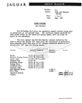
Service Bulletin
Bulletin
1/
ill.- - - - - - -
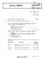
ISSUE
ISSUE NO:
NO:JD 04/92
APRIL 1992
SHEET:
SHEET: 1 OF 1
S.R.O: 82-25-13
82-25-14
MODEL
: XJ6/
S.111 V12 (AIR
(AIR CONDITIONED MODELS)
MODELS)
XJ61 XJS I/ 5.111
SUBJECT
: BLOWER MOTOR
MOTOR ASSEMBLIES
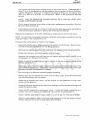
CUSTOMER CONCERN
squeak.
: Brush
Brush gear noisy operation, ie: low speed ticking I/squeak.
ADVICE TO CUSTOMER
: Installation
Installation of revised
revised blower motor assemblies incorporating
rating a new'P35' motor will overcome the noise concerns.
New blower motors have been
been introduced from the follow·
following
ing VINs:
VINs:
XJ6 (Air Con)
Con) -- 657163
657163
-- 183290
183290
XJS
5.111
-- 486002
S.III
486002
DEALER ACT1
ACTION
0N
: Yes
REPAIR
REPAIR METHOD
: Blower Assemblies incorporating
incorporating the new motor are interinterchangeable on
on vehicles prior to
t o the above VINs
VlNs (see
(see Parts
Information
Information below for model
model year variations).
should be
be carcarReplacement of blower motor assemblies should
ried
with
ried out in
in accordance w
i t h the following Service Manual
Manual
instructions:
XJ6 -- Volume 4, Section 82, Page 82-38/82-39
82-38/82-39
XJS -- Volume 4, Section 82,
82, Page 82-62/82-63
82-62/82-63
S.III
S.Ill -- Section 80-82,
80-82, Page 82-39/82-40
82-39182-40
SERVICE TOOLS
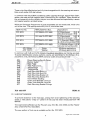
PARTS
PARTS INFORMATION
N/A
: Owing
Owing to the introduction of 'PM5'
'PMS' harness connectors
connectors on
blower motor assemblies fitted
fitted to XJ6 and XJS models
from VINs:
XJ6-629286
XJ6
- 629286
XJS -- 179737
179737
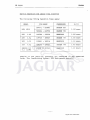
Part Numbers for replacement units on
on vehicles PRIOR to
the abovl3
above ViNs
VlNs are as follows:
follows;
XJ6
XJS
RH
RH
eBC
CBC 8966
8966
CCC 5546
cee
Jaguar Cars Limited
Limited
Jaguar
LH
LH
CBe
CBC 8967
8967
cce
CCC 5547
Jaguar Cars Limited 2005
JA~
JAGUAR
%
JD 04/92
04 192
Part Numbers for replacement units on
on vehicles FROM
FROM the
above VI
Vl Ns are as follows:
fol lows:
RH
RH
XJ6
XJS
lH
LH
5400
CCC 5400
5544
CCC
eee
eee
CCC 5401
5401
eee
5545
CCC
S.III V12
v12
The harness connector on
on Series III
Ill blower motors
motors has not
changed. For replacement units
units incorporating the new
motor, the following Part Numbers apply:
RH
RH
5.111
ADMINISTRATION
INFORMATION
INFORMATION
eee
CCC 5546
lH
LH
eee
CCC 5547
: WARRANTY CODES
CODES
XJ6
))
7TA
(RH)
7TAIRH)
XJS
)1
7TB (LH)
ILHI
S.III
5.111
754
REPAIR OPERATION
OPERATION CODES
XJ6/
XJ6 / XJS MODELS:
MODELS:
SRO 82-25-14
SRO 82-25-13
82-25-14 (RHI
(RH)
82-25-13 (LHI
ILH)
(SRO
(SRO
(SRO 82-25-14/09
82-25-1 4/09
(SRO 82-25-13/09
82-25-13/09
LESS
ALLOWANCE)
LESS JDS ALLOWANCE) LESS
LESS JDS ALLOWANCE)
5.111:
SRO 82-25-14 (RH)
SRO 82-25-13 (lH)
Jaguar Cars Limited 2005
A
-
III
Service Bulletin
I
1[----.
..
.
.
- --.. .
--
-.
-.
.-
DATE: OCTOBER 1991
1991
DATE:
1 of 7
PAGE: 1
REF: JD 08/91
08/91
REF:
ITEM: 49
49
ITEM:
XJS
WARRANTY
WARRANTY CODES
In
In the latest
latest edition of the
the XJS Warranty Code
Code book,
book, codes
codes for the battery
battery and
and spare
wheel
wheel covers
covers have
have been
been duplicated.
duplicated.
To
To rectify
rectify this situation
situation and
a n d prevent
prevent further confusion
confusion when submitting
submitting claims,
claims, the
the
following
codes
have
been
removed
from
the
warranty
system:following codes have been removed from the
system:-
CODE
CODE
DESCRIPTION
DESCRIPTION
90S
Spare Wheel
Wheel Cover
Battery
Battery Cover
Cover Boot
Boot
8PZ
with immediate
immediate effect,
effect, Dealers
Dealers shou
should
NOTsubrnitfurtherctaimsforthese
Therefore, with
Id NOT
subm it fu rther cIa i ms fa r these
codes.
codes.
All future
future claims
claims for
for the
the above
above parts
parts should
should be
be submitted,
submitted, using
using the
the following
following codes
codes
All
only:only:9DO
9DR
8NU
Battery
Battery Cover
Cover
Battery
Battery Cover
Cover Support
Support Panel
Panel
Spare
Spare Wheel
Wheel Cover
Cover
ITEM: 50
50
ITEM:
XJS
XJS (FACELlFT)
{FACELIFT)
WARRANTY
WARRANTY CODES
CODES
The
The following
following new
new warranty
warranty complaint
complaint:code
code has
has been
been allocated
allocated to
to cover
cover the
the fuel
fuel
gauge
gauge "anti-slosh
"anti-slosh module",
module", introduced
introduced on
on XJS
XJS Facelift
Facelift models.
models.
Code
Code
Description
Description
SRO
SRO
7JU
7J U
Anti-Slosh Module
Module
Anti-Slosh
88.25.25
88.25.25
JaguarCars
Cars Limited
Limited
Jaguar
Jaguar Cars Limited 2005
-h?=
JAGUAR
JA~
JD
JO 08/91
08 / 91
ITEM:51
51
ITEM:
ALL
ALL MODELS
MODELS
12
12 CYLINDER
CYLINDER PRESSURE
PRESSURE CHECK
CHECK
WARNING:
WARNING: Would
Would all
alltechnicians
technicians please
please note
notethat
that before
beforeperforming
performingaacylinder
cylinderprespresfrom the
sure
surecheck,
check, Repair
RepairOperation
Operation No.
No.12.25.01,
12.25.01,all
allfuel
fuel should
should be
bepurged
purgedfrom
thefuel
fuel rail.
rail.
Purging
Purging of
of the
the fuel
fuel rail
rail may
may be
be achieved
achieved by
by disconnecting
disconnecting the
the fuel
fuel pump
pump relay
relay and
and
then
then cranking
crankingthe
the engine
enginefor
for ten
ten seconds.
seconds.
XJ6 ALL
ALL MODELS
MODELS&& XJS
XJS 3.6/4.0
3.6 1 4.0
XJ6
ITEM:52
52
ITEM:
19
19 CRUISE
CRUISE CONTROL
CONTROL ACTUATOR
ACTUATOR LINKAGE
LINKAGE ADJUSTMENT
ADJUSTMENT
Shou
I d customer
plai nts be
ncrease in
se control
Should
customercom
complaints
bereceived
receivedof
ofani
an increase
inthe
thecrui
cruise
controlresponse
response
time
timeand
andaadegree
degreeof
of hunting
huntingof
ofthe
the set
setspeed,
speed,the
thecruise
cruise control
controlactuator
actuator linkage
linkageadadjustment
justment should
should be
bechecked
checked in
inaccordance
accordance with
withthe
thefollowing
following procedure,
procedure,before
beforetaktaking
ingany
anyfurther
further action.
action.
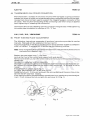
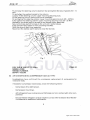
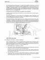
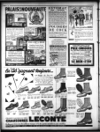
Dealers
Dealers should
should ensure
ensurethat
that the
theclearance
clearance between
betweenthe
the end
endof
of the
theactuator
actuator to
to throttle
throttle
link
linkslot
slot:(A
(AFig
Fig 1)
1)and
and the
the shoulder
shoulder bolt
bolt (8
( 0Fig
Fig 1)
1 )isisO.5mm
0.5mmto
to lmm
I m m {C
{CFig
Fig 1).
1).
S.R.O.
S.R.O.
Allowance
Allowance
Complaint
Code
Complaint Code
19.75.11
19.75.11
0.10
0.10 hrs
hrs
7VCP
7VCP
-
cQ~)}
x
FIG 11
FIG
2
Jaguar Cars Limited 2005
%
JAGUAR
JA~
JD 08/91
XJS V12
V12
XJS
ITEM:
ITEM:53
53
44 TRANSMISSION
TRANSMISSION OIL
OIL COOLER
COOLER CONNECTION
CONNECTION
44
There have
have been
been aa number
numberof
of oil
oil coolers
coolers returned
returned with
with damaged
damaged coupling
coupling connector
connector
There
bosses,
bosses, the
the cause
cause of
of which
which can
can be
be attributed
attributed to
to poor
poor workshop
workshop practice
practice where
where backbacking spanners
spanners have
have not
not been
been used
used to
t o support
support the
the integral
integral hexagon
hexagon connector
connector of
of the
the
ing
in aa fracturing
fracturing of
of the
the connecting
connecting tube
tube when
when torque
torque is
is applied
applied
oil cooler.
cooler. This
This results
results in
oil
upon tightening
tightening or
or loosening
loosening the
the connection.
connection.
upon
Technicians
should use
useaa backing
backing spannerto
spanner t o hold
hold the
the integral
integral boss
boss whilsttightening
whilst tightening
Techn
icians should
the cooler
cooler pipe
pipe connection
connection to
t o aa torque
torque of
of 15
15-- 17
17 Nm.
Nm.
the
XJ6 I/ XJS
XJS I/ 5.1111
S.llt / LIMOUSINE
LIMOUSINE
XJ6
ITEM:54
54
ITEM:
60 FRONT
FRONT HUB
HUB END
END FLOAT
FLOAT ADJUSTMENT
ADJUSTMENT
60
The following
following instructions
instructions supersede
supersede all
all previous
previous instructions
instructions provided
provided in
in service
service
The
Manuals will
will be
b e updated
updated at
at the
the next
next reprint.
reprint.
manuals. Manuals
manuals.
hubend
end float
float on
on the
the above
above models
models should
should be
be set
set between
between 0,0254
0,0254 to
to 0,0762mm
0,0762mm
Front hub
Front
(0.001
(0.001to
to 0.003in).
0.003in). To
To achieve
achieve this
this in
i n service
service use
use the
the following
following method:
method:
N2te::
Note: Prior
Priorto
to adjusting
adjustingthe
t h e hub
hubend
end float
float an
an absorbent
absorbentcloth
clothshould
should be
be placed
placed around
around
the brake
brake fluid
fluid reservoir
reservoir cap.
cap.
the
Slacken the
the road
road wheel
wheel nuts
nuts 1/ 4 turn
Slacken
turn each.
each.
Jack up
up the
the front
front of
of the
the vehicle
vehicle and
and support
support with
with axle
axle stands.
stands.
Jack
Removeone
onewheel
wheel nut,
nut, mark
markthe
the wheel
wheel relative
relativeto
to the
the stud
stud and
and remove
removethe
theremaining
remaining
Remove
wheel nuts.
nuts.
wheel
the roadwheel
roadwheel and
and tyre
tyre assembly.
assembly.
Remove the
Remove
upon model,
model, gently
gently prise
prisethe
the brake
brake pads
padsfree
free or
or manipulate
manipulatethe
the brake
brakecaliDependent upon
Dependent
caliper to
to ensure
ensure tthe
h e brake
brake pads
pads are
are free
free within
within their
their mounti
mountings,
i.e. the
the disc
disc isis free
free to
to
per
ngs, i.e.
rotate.
rotate.
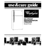
off the
the hub
h u b grease
grease cap
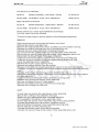
cap (1
(1Fig.
Fig. 1)
1).
Prise off
.
Prise
Fit
. 2).
Fit aa Dial
Dial Test
Test Indicator
Indicator (DTI)
(DTI)to
t o the
the hub
hub (Fig
(Fig.
2).
Graspthe hub
hub unit.
unit. Firmly
Firmly pull
pult and
and push
pushthe
the unit,
unit, oscillating
oscillating atthe
atthesametime,todeGraspthe
same time, to determine
termine the
the OTI
DTI end
endfloat
float reading.
reading.
the reading
reading is
iswithin
within the
the specification
specification quoted
quoted there
there is
isno
no need
needto
tocarry
carryout
outthe
the adjustadjustIfIfthe
ment. IfIf not,
not, remove
remove the
the hub
hub nut
nut split
split pin
pin and
and cover
cover (2,
(2, 33 Fig.
Fig. 1).
1).
ment.
D',
'C.
Fig.2
Fig. 2
Fig.
Fig. 11
3
Jaguar Cars Limited 2005
-&
JAGUAR
JA~
JD 08/91
08 191
Note:
Note: For
For identification
identification purposes
purposes only,
only,
Fig.1
Fig. 1 shows XJS, S III
Ill &
& limo.
Limo. type hub.
hub.
Fig.
Fig. 2 shows XJ6 hub.
Adjust the
the nut,
nut, as necessary,
necessary, to
to give
give a reading
reading of O,OS08mm
0,0508mm ++ /I- O,0254mm
0,0254mm (O.002in
(0.002in
+
+ / -- 0.001in).
0.001in).
Always try to
t o achieve
achieve the
the mid-point
mid-point of the
the tolerance
tolerance i.e.,
i.e., O,0508mm
0,0508mm (O.002in).
(0.002in).
Align the
the hub
hub nut
nut cover and
and secure
secure with
with a new
new split pin.
pin.
When
When the
the newsplit
new split pin
pin is
is fitted, ensure
ensure the
the end
end float is
is re-checked
re-checkedusingthe
using the DTI
DTIgauge
gauge
(Fig.
(Fig. 2).
2).
If
If necessary,
necessary, re-adjust using
using the
the same
same method,
method, until
until the
the end
end float is
is correct.
correct.
Alwavs
by checking
checking with
with a DTI
DTI gauge.
gauge.
Always finish
finish the
the adjustment by
Always ensure
ensure the
the end
end float is
is within
within the
the limits
limits quoted.
Refit
Refit the
the grease
grease cap.
cap.
Refit
Refit the
the road
road wheel.
wheel.
Carry
out
the
adjustment
procedure
out
the
adjustment
procedure on
on the
the opposite
opposite front hub.
hub.
Carry
When
When finished,
finished, lower
lower the
the vehicle
vehicle from
from the
the stands.
stands.
Ensure
Ensure the
the wheel
wheel nuts
nuts are
are tightened
tightened to
to the
the specified
specified torque.
torque.
Remove
fluid reservoir
Remove the
the absorbent
absorbent cloth
cloth from
from around
around the
the brake
brakefjuid
reservoir cap,
cap, ensuring
ensuring the
the
area
area is
is clean
clean and
and dry.
dry.
Before
the vehicle, pump
pump the
the brake
brake pedal
pedal to
to centralise
centralise the
the pads.
pads.
Before moving
moving the
ITEM: 55
55
ITEM:
ALL
ALL MODELS
MODELS
77
77 BODY
BODY REPAIR
REPAIR
To
To avoid
avoid the
the risk
risk of causing
causing permanent
permanent damage
damage to
to vehicle
vehicle ECUs
ECUs during
during body
body repairs,
repairs,
the
following
precautions
must
be
observed
prior
to
using
any
electrical
welding
the following precautions must be observed prior to using any electrical welding
equipment.
equipment.
1. Disconnect
Disconnect the
the vehicle
vehicle battery
battery and
and alternator.
alternator.
1.
2.
area of
any panels
2. Disconnect
Disconnect and
and removea!1
removeall ECUs
ECUs in
inthe
the immediate
immediatearea
ofany
panelsto
to beelectri·
beelectrically
welded. As
As aa general
general rule,
rule, all
all ECUs
ECUs within
within 22 feet
feet of
of the
the area
area to
to be
be welded
welded
cally welded.
should
be removed;
removed; for
for more
more detailed
detailed information,
information, refer
refer to
to the
the relevant
relevant Service
Service
should be
Manual.
Manual.
3.
3. When
When using
using welding
welding equipment,
equipment, the
the earth
earth return
return clamp
clamp should
should be
be located
located as
as
close as
as possible
possible to
t o the
the area
area of
of repair.
repair.
close
XJ6
XJ6 ALL
ALL MODELS
MODELS
ITEM:
ITEM: 56
56
82
82 DRIVER'S
DRIVER'S BLOWER
BLOWER MOTOR
MOTOR ASSEMBLY
ASSEMBLY
The
The repair
repair operation
operation time
time for
for renewing
renewing the
the driver's
driver's side
side blower
blower motor
motor assembly
assembly has
has
changed
changed on
on all
all XJ6
XJ6 Vehicles
Vehicles from
from VIN
VIN 629286.
629286.
The
The repair
repair operation
operation times
times are
are now
now as
as follows:follows:-
4
Jaguar Cars Limited 2005
-k
JA~
JAGUAR
JD 08/91
08 191
Left Hand
Hand Drive
Drive Vehicles:
82.25.13
82.25.13
Blower assembly -- Left Hand
Hand -- Renew
82.25.13/09
82.25.13109 As 82.25.13
82.25.13 (Less
(Less J.D.S. Allowance)
01.25 Hours
00.90 Hours
Hours
Right Hand
Hand Drive Vehicles:
82.25.14
Right Hand
Hand -- Renew
Blower Assembly -- Right
01.25 Hours
Hours
82.25.14/09
82.25.14109
As 82.25.14
82.25.1 4 (Less
(Less J.D.S.
J.D.S. Allowance)
00.90 Hours
Hours
Please
Please amend your repair time schedules accordingly.
No
No other repair times are affected.
To achieve these times in
i n service, adhere to the following procedure:procedure:REMOVE
REMOVE
Open the bonnet and disconnect the battery earth
earth lead.
Remove
Remove the driver's side dash
dash liner.
Remove
Remove the retaining
retaining clip from the air conditioning unit's pliable
pliable trunking.
Displace the pliable trunking from the air conditioning unit.
unit.
Displace the relay bases from their mounting
mounting brackets.
Displace
Cut and remove
remove the ratchet straps securing the brake switch
switch harness.
Disconnect the vacuum hose from the blower motor assembly servo unit.
Disconnect the blower motor mUlti-way
multi-way connectors.
Undo and remove
remove the steering column lower mounting
mounting securing nuts.
nuts.
Undo and
and remove
remove the steering column upper mounting securing nuts.
Lower the steering column
column assembly.
Retrieve
Retrieve the column upper packing shims.
Remove
Remove the washer bracket from the column.
Manoeuvre the steering column
column towards the centre of the vehicle for access.
Undo and remove
remove the steering column
column outer stabilizer bar's upper and lower securing
nuts.
nuts.
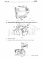
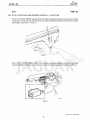
Displace and rem
ove the steering column
remove
column stabilizer bar (Fig.
(Fig. 1).
1).
Reposition
Reposition the vehicle harness connectorsto
connectors to gain access to
t o the blower motorassembly securing bolts.
Undo and
and remove the blower motor assembly securing bolts.
Displace
remove the blower motor assembly.
Displace and remove
Remove
Remove and discard the unit intake gasket.
Remove
Remove the pliable trunking to
t o assembly securing tape.
Remove the trunking from the unit.
Remove
REFIT
REFIT
Fit and align
align trunking
trunking to
t o the new blower motor assembly.
tape.
Secure the trunking to the assembly with tape.
Smear the new intake gasket with a suitable adhesive.
Fit the gasket to
t o the blower motor assembly intake.
and align
align the blower motor assembly into its mounting
mounting position.
position.
Fit and
Connect the pliable trunking to
t o the air conditioning unit.
unit.
Refit and tighten the blower motor assembly securing bolts.
Fit
F i t and
and align
align the trunking retaining
retaining clip.
Connect the blower motor multi-way
multi-way connectors.
Connect the vacuum hose to
t o the blower motor assembly servo unit.
5
Jaguar Cars Limited 2005
%
JAGUAR
JA~
JD 08/91
08 1 97
Fit and align the steering
steering column stabilizer bar and tighten the securing bolts
bolts (10 -14
- 14
Nm).
Nm).
Fit and align the washer bracket to the column.
Loosely fit the steering column
column upper mounting
mounting securing nuts.
Fit the steering column
column packing
packing shims as necessary.
Fit and tighten the steering column
column lower mounting securing
securing nuts
nuts (20
(20 - 22 Nm).
Nm).
Fully tighten the steering column
column upper mounting securing nuts (20
(20-- 22 Nm).
Nm).
Reposition
Reposition the brake switch harness
harness to the blower motor assembly.
Secure the brake switch harness to the unit with ratchet straps.
Fully seat the relay bases
bases to their mounting brackets.
brackets.
driver's dash liner assembly.
Refit the driver's
Reconnect the battery earth lead and close the bonnet.
bonnet.
-
Fig. 1
Fig.
ITEM:
ITEM: 57
S.III,
S.111, XJS &
& XJ6 UP
UP TO VINs:VINs:506664 -- USA
506448
506448 -- CANADA
507471 - R.O.W.
R.O.W.
507471
-
82
82 AIR CONDITIONING COMPRESSOR (GM
(GM A6 TYPE)
TYPE)
Investigations have confirmed the unnecessary replacement of compressors for
noise and leaks.
leaks.
If excessive
excessive compressor noise exists, check the following items:items:-
.
Compressor drive belt tension.
Compressor mountings.
.
,
AlC
routing (ensure
N
C refrigerant
refrigerant hose routing
(ensure that hoses are not in
in contact with other components).
.
ponents),
refrigerant charge weight is correct (referto Section 82 of the SerEnsure that the refrigerant
vice Manual for additional
additional information).
information).
6
Jaguar Cars Limited 2005
-
JA~
JAGUAR
08/91
JD 08
/ 91
.
Ensure that the compressor is filled to the correct level with oil. A MAXIMUM of
ee) of refrigerant oil can be added to the compressor without discharg4 ozs ((114
114 cc)
(such as 'Snap-on'
'Snap-on' oil injector tool
ing the refrigerant. Using an oil injector tool (such
111),
(57 ccc}
c } increments. (Refer to the procedure detailed
ACT 11
11, add oil in 2 oz (57
below).
below).
NOTE: LOW
lOW OR EXCESSIVE CHARGE WEIGHT OR A LOW
lOW OIL
Oil LEVEL WILL
CAUSE COMPRESSOR NOISE.
NOISE.
.
Clutch drag or bearing noise (refer to the clutch replacement procedure, Section
82 of the Service Manual).
.
replaced in accordance
Compressors which leak oil or Freon must have the seals replaced
with the procedure detailed in Section 82 of the Service Manual.
above-mentioned items.
Replace the compressor only after checking all of the above-mentioned
NOTE: All returned compressors must be complete and sealed, using the blanking
NOTE:
plate provided on the replacement unit.
Procedure for compressor oil injector tool usage:usage:Ale system. Make sure that the system is full of Freon. Referto
SecOperate the A/C
Refer t o SetManual for the test procedure.
tion 82 of the Service Manual
.
Remove the sealing gaps from the high and low pressure A/C
Ale charging points.
.
closed.
Check that the valve on the oil injector tool is closed
Remove
Remove the threaded end cap from the
t h e oil injector tool and
and add
add 2 ozs (57
I57 ee)
cc) of
compressor oil. Replace
Replace the end cap.
cap.
Attach the short flexible hose on the oil injector to the low pressure fitting of the
vehicle A/C
AlC system.
.
AlC system extension hose to the fitting on the side of the
Attach one end of an A/C
valve ofthe
of the oil
oil injector tool. Attach the other end oftha
of the extension hose to
t o the high
high
pressure
AlC
pressure fitting of the vehicle N
C system.
Run
Run the engine at
a t idle
idle with the AIC
A/C system
system operating.
.
Slowly open
open the oil
oil injector tool
tool valve until
until it is
is fully open. Allow the oil
oil to
t o flow
into the compressor for 2 minutes.
minutes.
.
Close
Close the oil
oil injector tool
tool valve. let
Let the engine run
run an
an additional minute, then
then
switch
switch off the ignition.
.
Carefully remove
from the high
remove the charging
charging hoses
hosesfrom
high and
and low pressure fittings and
and
install
install the sealing caps.
.
Check the
the AlC
A/C system
system for compressor noise.
noise. If noise
noise still
still exists, repeat
repeat the
the proprocedure
cedure once
once more,
more, adding
adding an
an additional 22 ozs
ozs (57
(57 ee)
cc) of compressor oil.
.
NOTE: NEVER ADD MORE
MORE THAN
THAN 4 OZS
OZS (114
(11 4 cc)
c c ) OF
OF Oil
OIL TO
TO THE
THE Ale
A/C SYSTEM.
SYSTEM.
.
self-adhesive label
label to
t o the
the AlC
PJC hose
hose (adjacent
(adjacent to the
the low pressure
pressure hose
hose
Attach a self-adhesive
fitting), stating
stating how
how much
much oil
oil was
was added
added and
and the
the date.
date.
7
Jaguar Cars Limited 2005
IIr1
II
I
III
JA~
Service Bulletin
Bulletin
DATE:
DATE: NOVEMBER
NOVEMBER 1991
1991
PAGE:
PAGE: 11 of 55
REF:
REF: JD
JD 09/91
09/91
ERRATA
ERRATA
Would Dealers
Dealers please
please note
note that
that in
in Service
Service Bu
Bulletin
JD 05/91,
05/91, Item
Item 31
31 "Forged
"Forged Alloy
Alloy
Would
Iletin JD
t h e Part
Part No.
No. for the
the XJS
XJS road
road wheels should
should be
be CSC
CBC 6175
6175 (not
(not CSC
CBC 9175).
9175).
Wheels", the
XJ6 MODELS
MODELS
XJ6
ITEM:
ITEM: 58
58
44
44 TRANSMISSION
TRANSMISSION FRONT
FRONT PUMP
PUMP ASSEMBLY
A new
new front
front pump
pump assembly
assembly has
has been
been introduced
introduced which
which cannot
cannot be
be retro-fitted
retro-fitted to
to
A
earlier models
models as
as the
the intermediate
intermediate plate
plate is
is not
not compatible.
compatible.
earlier
Should
ission unit,
Should this
this later
later type
type be
be fitted
fitted inadvertently
inadvertently to
t o an
an earlier transm
transmission
unit, the
the interinternal pressures
pressures created
created will
will blow-out
blow-out the
the pump
pump seal
seal (this
{this is
is because
because the
the ventilation
ventilation
nal
channel is
is now
now in
i n a different position).
position).
channel
Part No.
No.
Part
I Qty
Q ~ YI
Description
Description
2.9,3.2 &
& 3.6
3.6 Litre
Litre Models
Models
2.9,3.2
Up to
to Gearbox
Gearbox Serial
Serial No.
No. 1158414:
1158414:
Up
JLM 1957
1957
JLM
11
Front
Front Pump
Pump Assembly
JLM 885
885
JLM
1
Intermediate Plate
Plate
JLM 2286
2286
JLM
11
Front Pump
Pump Assembly
Front
JLM 10715
10715
JLM
11
Intermediate
Intermediate Plate
Plate
JLM 10441
10441
JlM
JLM 10448
10448
JLM
1
Front
Front Pump
Pump Assembly
11
Intermediate
Intermediate Plate
From Gearbox Serial
Serial No.
No. 35366:
35366;
From
JLM 10716
10716
JLM
,
1
Front
p Assembly
Front Pum
Pump
JLM 10717
10717
JLM
1'1
Intermediate
Intermediate Plate
Plate
,
II
From Gearbox Serial No.1
No. 115841
53
From
158415;
Litre Models
Models
4.0 Litre
Up to Gearbox Serial
Serial No.
No. 35365:
Up
Jaguar Cars
C a n Limited
Limited
Jaguar
Jaguar Cars Limited 2005
IIIII
~ A G U
JA~
=Q%
Service
Service Bulletin
Bulletin
.,.
III
DATE: OCTOBER
OCTOBER 1992
1992
DATE:
PAGE: 11 ofS
of 8
PAGE:
REF: JD
JD 16/92
16/92
REF:
ERRATA
ERRATA
Owing
Owing to
to revised
revised information,
information, the
the torque
torque figure
figure far
for the
the coolant
cooiant temperature
temperature transtransmitter
mitter to
to engine,
engine, XJS
XJS models,
models, is
is 14,5
14,5 to
to 19,5
19,5 Nm.
Nm.
The
The torque
torque figure
figure given
given in
in Service
Service Bulletin
Bulletin JD
JD 10/92
10192 and
and Section
Section 88
88 of
of XJS
XJS Service
Service
Manual,
Manual, JJM
JJM 100406/20,
10 04 06/20,should
should be
be ignored
ignored and
and only
only the
the revised
revised figure
figure used.
used.
Service
Service Manuals
Manuals will
will be
be amended
amended at
at the
the next
next reprint.
reprint.
ITEM: 44
44
ITEM:
XJ6
XJ6 93
93 MY
M Y (FROM
(FROM VIN
VIN 667829)
667829)
BATIERY
BA-TTERY TRANSIT
TRANSIT RELAY
RELAY -- REMOVAL
REMOVAL
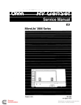
Owing
Owing to
to the
the relocation
relocation of
of the
the battery
battery into
into the
the boot
boot at
a t 93
93 MY,
MY, aa revised
revised battery
batterytransit
transit
relay
relay has
has been
been introduced,
introduced, (see
{see Fig
Fig 1).
1).
FIG 11
FIG
The
The procedure
procedure for
for the
the removal
removal of
of this
this new
new relay
relay is
is as
as follows:
follows:
WITH THE
THE IGNITION
IGNITION OFF:
OFF:
WITH
1.
1. Open
Open the
the boot
boot and
and remove
remove the
the battery
battery cover,
cover, (see
(see Fig
Fig 2).
2).
2.
2.
Remove
Remove the
the negative
negative lead
lead from
from the
the battery.
battery.
3.
3. Disconnect
Disconnect the
the transit
transit relay
relay from
from the
the battery.
battery.
Jaguar Cars Limited 2005
4.
yellow (W/Y)
4. Remove
Remove the
the white
white I/yellow
(WN) ignition
ignition wire
wire from
from the
the transit
transit relay.
relay.
A
JAGUAR
JA~
JD 16/92
FIG
FIG 2
Remove the
the positive
positive lead
lead from
from the
the transit relay
relay terminal
terminal post,
post, (A,
(A, Fig
Fig 3).
3).
5.
5. Remove
Fig
6.
6. Reverse
Reverse the
the positive
positive lead
lead clamp
clamp and
and refit
refit the
the clamp
clamp to
to the
the positive
positive lead
lead (B,
(6,
Fig 3).
3).
=-=-==='====-::~
J'S117t!ol
FIG
FIG 33
7.
7.
Displace
Displace the
the battery.
battery.
8.
yellow (W/Y)
8. Tie
Tie back
back and
and secure
secure the
the white
white I/yellow
( W H ) ignition
ignition wire,
wire, (see
(see Fig
Fig 4).
4).
FIG 4
J:' .... I~IIDI:' TU AT TUIC I I:'An Cl!I:'MAII\IC C1
Jaguar Cars Limited 2005
n I v 11\1<:111 ATl:n \lI.n.II:::1\I <:I:rl u:u::::n
-
JAGUAR
JA~
JD
JD 16/92
16 1 9 2
9.
9.
Refit
Refit the
t h e battery.
battery.
10. Refit
Refit: and secu.re
secu,re the positive
positive and
and then
then negative
negative lead
lead of the battery.
battery.
11.
1 1. Replace
Replace the
the battery
battery cover.
cover.
NOTE:
NOTE:
ALL
DEALERS MUST
CONTINUE TO RETURN THE DISPLACED
TRANSIT
ALL UK
UKOEALERS
MUSTCONTINUETORETURNTHE
DISPLACEDTRANSlT
RELAYS.
RELAYS.
REMOVAL
REMOVAL OF
OF THE
THE TRANSIT RELAY
RELAY SHOULD
SHOULD BE
BE CARRIED
CARRIED OUT
OUT NO
LONGER
THAN
24
HOURS
BEFORE
THE
VEHICLE
IS
HANDED
OVER
TO THE
LONGER THAN 24 HOURS BEFORE THE VEHICLE IS HANDED OVERTOTHE
CUSTOMER.
THE
THE RADIO
RADIO AND
AND TIME
TIME CLOCK
CLOCK MUST BE
BE RESET
RESET AFTER THE
THE RELAY
RELAY IS
1s RE·
REMOVED.
MOVED.
IMPORTANT:
N O CIRCUMSTANCES
CIRCUMSTANCES SHOULD
SHOULD THE
THE RELAY
RELAY BE
BE USED
USED OR RE·
REIMPORTANT: UNDER NO
TAINED
TAINED AS
AS AN
AN ISOLATION
ISOLATION DEVICE
DEVICE FOR
FOR ROAD
ROAD USE.
USE.
XJS
ITEM: 45
03
03 REPAIR
REPAIR OPERATION
OPERATION TIMES
TIMES
Air Conditioning
Conditioning Blower
Blower Motor
Motor Assembly
Assembly
The
The repair
repair operation
operation times
times for
for renewing
renewing the
the air
air conditioning
conditioning blower
blower motor
m o t o r assem·
assernblies
blies have
have been
been re-studied
re-studied on
on 1992
1992 MY
MY vehicles.
vehicles.
The
The new
new operation
operation times
times for vehicles
vehicles from
from VIN
VIN 179737
179737 are
are as
as follows:
follows:
Right-hand drive
drive vehicles
vehicles
Right-hand
-
82-25-13
Blower
82-25-13
Blower Assembly -left-Hand
Left-Hand -- Renew
Renew
82-25-13/09
82-25-1 3/09 As
As 82-25-13
82-25-1 3 (Less
(Less JDS
JDS Allowance)
Allowance)
0.95
0.95 Hrs
Hrs
0.60
0.60 Hrs
Hrs
82-25-14
Blower
Assembly - Right-Hand - Renew
82-25-14
BlowerAssembly-Right-Hand-Renew
82-25-14/09
82-25-1 4/09 As
As 82-25-14
82-25-1 4 (Less
(Less JDS
JDS Allowance)
Allowance)
1.60
Hrs
1-60Hrs
1.25
1.25 Hrs
H rs
Left-hand
Left-hand drive
drive vehicles
vehicles
Blower Assembly -- Left-Hand
Left-Hand -- Renew
Renew
82-25-13
Blower
82-25-1 3
82-25--13/09
82-25-1 3/09 As
As 82-25-13
82-25-13 (less
(Less JDS
JDS Allowance)
Allowance)
1.60
1.60 Hrs
Hrs
1.25
1.25 Hrs
Hrs
82-25-1 4
Blower Assembly
Assembly -- Right-Hand
Right-Hand -- Renew
Renew
82-25-14
Blower
82-25-14/09
82-25-24/09 As
As 82-25-14
82-25-14 (Less
(Less JDS
JDS Allowance)
Allowance)
0.95 Hrs
Hrs
0.95
0.60
0.60 Hrs
Hrs
Please
Please amend
amend your
your repair
repair times
times accordingly.
accordingly.
No
No other
other repair
repair times
times are
are affected.
affected.
Jaguar Cars Limited 2005
=+b
JA~
JAGUAR
JD 116/92
JO
6 1 92
ITEM: 46
46
XJ6/1 XJS
XJS
XJ6
RECOMMENDATIONS
10 BRAKE SYSTEM SERVICE RECOMMENDAT1ONS
This bulletin supersedes
supersedes Item 21
21 of
of Service Bulletin JD
JD 03/92.
03/92.
Note: This
With the introduction of the ABS brake system, from the following VINs, the brake
servicing recommendations have changed:
1. XJ6 from VIN 594576.
2.
(5.3 convertible)
convertible) from VIN 147269.
XJS (5.3
(5.3 coupe) from VIN 148782.
3. XJS (5.3coupe)
4.
(3.6 coupe) from VIN
V1N 148945.
XJS (3.6
necessary. The system and components,
No routine replacement of system seals is necessary.
which are sealed for life, require no maintenance. Repair is by replacement.
inspected for satisfactory operation and condition
condition
The braking system must still be inspected
service intervals.
intervals.
at the regular service
nature, brake fluid must be renewed
renewed at 2 year or 30 000
Because of its hygroscopic nature,
(48 000 km)
km) intervals,
intervals, whichever is sooner.
mile I48
XJ6 ALL MODELS
ITEM: 47
18
18 LAMBDA SENSOR SPLASH-SHIELD
SPLASH-SHIELD
Following reports
reports of the intermittent
intermittent display of "Fuel
"Fuel Failure
failure 44" on
on the instrument
pack, it was found
found that this symptom could
could be
be caused
caused bywater
by water penetrating
penetrating the lambda sensor.
sensor.
A
A lambda
lambda sensor splash-shield
splash-shield has
has been
been introduced
introduced from
from VIN
V1N 664941,
664941, which
which can
can be
be
fitted
fitted retrospectively and
and should
should be
be installed
installed whenever a lambda sensor is
is changed.
changed.
This
This will
will reduce
reduce the possibility
possibility of water ingress.
ingress.
/~
Jaguar Cars Limited 2005
%
JA~
JAGUAR
JD16/92
JD 16 1 9 2
heat-proof sleeve
sleeve is fitted by sliding it over the sensor, prior to its
its
The six-inch silver heat-proof
replacement. After the sensor has been
been fined,
fitted, Dealers
Dealers should ensure thatthe
that the sleeve
is
SOL
i s pushed
pushed fully back down to cover the whole sen
sensor-
ALL MODELS
MODELS
ITEM: 48
18 IGNITION SPARK PLUGS
PLUGS
Spark plugs
plugs have been
been returned
returned under warranty with a yellow I/ brown
brown stain
stain visible
on the insulator housing. Dealers
Dealers have
have incorrectly interpreted
interpreted this as leakage
leakage of comcornbustion
bustion gases between
between the insulator and
and metal
metal housing and
and the cause
cause for
for spark plug
plug
misfire. Thefollowing
The following is
i s an explanation forthe
for the staining and
and the more
more likely cause for
spark plug
plug misfire.
During mostatmospheric
most atmospheric conditions a form of
o f static
staticdischarge,
c o m m o n to high
high voltDuring
discharge, common
conductors, can occur.
occur, which IS
is commonly known
known as "Corona discharge".
age conductors,
Ignition
prone t o this effect during wet weather, when the air
Ignition systems are particularly proneto
space surrounding
surrounding the spark plugs becomes
becomes charged with a gas composed
composed of elecelectrons, ions and
and air particles,
particles, forming
forming a state of general
general ionization.
ionization. Too much
much ionizionization counteracts the spark plug
plug insulation and causes a partial
partial discharge, which in
in
turn gives out a blue
blue light.
light.
in no way affect the running
running ofthe
of the car, providcircumstances this will in
Under normal circumstances
ing
ing the spark plug
plug insulators
irlsulators are kept clean.
onlyoccur
if the spark plug insulators were coated
Running
Runni
n9 problems would normally only
occur ifthe
in a film of dirt, which would allow high
high voltage tracking, known
known as "flashover",
"Rashover", bein
plug terminal stud
stud and earth, thus causing
causing a misfire.
tween the spark plug
However,
provided against this eventuality by the inclusion
inclusion of "ribs"
"ribs"
However, protection
protection is provided
body. To identify whether or notthe
not the spark plugs have been
been subsubalong the insulator body.
jected to Corona
Corona discharge.
discharge, plugs should be examined
examined in
in daylight for the presence
presence
brown stain
stain at the base of the insulator, next to the metal
metal housing.
housing.
of a yellow I/ brown
The actual stain
stain is caused
caused by oil-contaminated
oil-contaminated particles,
particles, in
in suspension
suspension around
around the
spark plug
plug insulator, receiving the electrostatic charge of ionization
ionization and
and fusing themthemselves to the plug. The stain
wiped off easily.
stain is quite harmless
harmless and can
can usually be
be wiped
Corona discharge
discharge will cause
cause no deterioration in
i n service
service or malfunction of the spark
Corona
plug.
plug.
Corona discharge does not. Cleanliness
Cleanliness
Moisture or dirt may cause "flashover" but Corona
is
is vital, therefore, spark plug
plug insulators
insulators should
should be kept clean
clean and
and dry at all times.
Note:
Note:
returned under warranty may be rejected
rejected as "no fault found"
Spark plugs returned
for the reasons
reasons given
given above.
XJ6 ALL MODELS
MODELS
64
64 REAR SHOCK ABSORBERS
ITEM~
49
Jaguar Cars Limited 2005
From VIN
VIN 667829.
667829, a new rear shock absorber is fitted to
t o all
all non-ride-Ievelling
non-ride-levelling veFrom
interchangeable with all previous
previous components when
hicles. This new part is fully interchangeable
'==-%
JA~
JD 16/92
16 / 92
JAGUAR
This new part, number CCC 6923, should be
be used
used in
in all cases where rear shock absorbers are replaced, with immediate effect.
Under no circumstances should this new part be mixed
mixed with old condition parts on
on
a vehicle axle.
When failures are identified
identified in
in service, single shock absorbers only need
need to
t o be
be
changed if the parts have less than 25,000 miles (40,OOOkm}
(40,000km) service use.
The new units, which have
have a black finish, can
can be
be easily distinguished from the previous parts by a new sealed gaiter, which will reduce dirt ingress.
ingress.
XJS 6CYl/
GCYL I V12 AND SERIES III
111 V12
ITEM:
ITEM: 50
50
82 RECEIVER
RECEIVER DRIER BOTTLE
BOTTLE
When replacing
replacing the receiver drier bottle, Part Number CAe
CAC 1881,
1881, it is essential that
the receiver drier bottle
vertical. This is
bottle is mounted
mounted with
w i t h the sight glass
glassvertical.
is to ensure that
the pick-up
pick-up tube inside
inside the drier bottle is always immersed
immersed in
in liquid
liquid refrigerant.
refrigerant. Ifthe
If the
receiver drier bottle is mounted
at
angles
in
excess
of
+j~
20
degrees
from
the
vertical,
mounted
in
+1-20 degreesfrom
there is a risk, under certain conditions, that vapour rather than liquid
liquid may enter the
pick-up
pick-up tube. Should this occur.
occur, erratic air conditioning performance
performance may result.
result.
ITEM:
ITEM: 51
51
XJS 4.0l
4.01 I/ V12
86
86 LOW COOLANT WARNING LIGHT
LIGHT FAULT
FAULT DIAGNOSIS
DIAGNOSIS
Dealer investigations into low coolant warning light concerns have resulted
resulted in
in a high
high
number of low coolant probes
probes and control units being
being rep/aced
replaced unnecessarily,
unnecessarily, as
most probes
probes and
and control units tested by the supplier reveal
reveal no
no faults. In
In order to re~
reduce this unnecessary replacement.
replacement, the following
following electrical checks should be
be carried
out by Dealers before condemning
condemning or replacing components where the cause is
found to
should include inspection ofthe
t o be loweoolant
low coolant level. The checks
checksshould
of the coolant system
tern for leaks.
leaks, which is best achieved
achieved by pressure testing the coolant system to
t o locate
the source of the leak.
Coolant leaks may be caused by: loose hose clip connections,
connections, worn or damaged
damaged pressure cap seals, or damaged hoses. Lack of coolant recovery from
f r o m the atmospheric
recovery bottle may be
be a further reason
reason for low
tow coolant level
level in
in the header tank.
Transfer of coolant from
f r o m the atmospheric recovery bottle relies
relies on the presence of a
vacuum, as the coolant contracts when the engine is turned off. Checks should
should be
be
made to ensure that the recovery bottle and
and its connections through to the header
made
tank are leak-free
leak-free and
and unrestricted.
unrestricted. In
In addition, the vacuum valve in
in the header tank
should be
be checked
checked to
t o ensure that it operates correctly and does not stick.
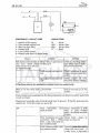
ELECTRICAL CHECK PROCEDURE
PROCEDURE
CIRCUIT I SYSTEM
S Y S f EM DETAILS
DETAILS
Jaguar Cars Limited 2005
The system operates by measuring the
t h e resistance
resistance of the coolant.
coolant. With resistance
below 5,000 Ohm,
Ohm, the warning light is off. The light will illuminate with the resistance
%
JAGUAR
JA~
JD
JD 16/92
16/92
, _ _ _.;..:w'--_-----,
W/R
w/u
II 1--_--..:8=------,
6
2
COMPONENT
CIRCUITCODE
CODE
COMPONENT I/ CIRCUIT
WIRING
WIRING CODE
CODE
11-Ignition
- Ignition (lGN)
(IGN)supply
supply
- Lawcoolant
coolantcontrol
control unit
unit
22 -low
light (Will
(W/L)
33--Warning
Warning light
Headertank
tank
44 --Header
Low coolant
coolant probe
probe
55 --low
Headertank
tankearth
earth via
via fixing
fixing bolts
bolts
66--Header
W
W
W/R
W/R
W/U
W/U
BB
FAULT
FAU LT
-- White
White
White I/ Red
Red
-- White
White I/ Blue
Blue
-- White
-- Black
Black
ACTION
ACT10N
CAUSE
CAUSE
WfLdoes
does not
notilluminate
illuminateat
at Blown
W/l
BlownW/l
W/L or
or open
open circuit
circuit
aany
n y time.
time. (Bulb
(Bulb check
check on
onW/L
W/L wire
wire
doesnot
notoccur
occurLe.
i.e.@
@11sec
sec
does
on
on following
following ign)
ign)
Earthwire
wireat
at unit
unitopen
opencircirEarth
cuit
cuit
Check
Check by
by shorting
shorting white
white fI
blue
(W/U)
wire
to
earthblue (W/U) wire to earth W/l
W/L should
should come
come on.
on.
Check
Check resistance
resistance to
to good
good
chassis
chassis ground
ground-less
-less than
than
22 Ohm.
Ohm.
Check supply
supply at
at unit,
unit,
Ign
cir- Check
lgnsupply
supplyto
tounit
unitopen
opencirshould
cuit
cuit
should be
bebattery
batteryvoltage.
voltage.
Ifthe
If the above
above checks
checks are
are satisfactory
sarisfactorv replace
replace faulty
faultv low
low coolant
coolant unit.
unit.
W/l
Lowcoolant
coolant
W/L on
on all
all the
the time
time with
with Low
tgn
ign
Check and
'Check
and top
top up
up as
as rerequired
quired
thecoola
coolant
level isissatisfactory,
satisfactory,the
thefollowi
following
checkwi
will
determine
which
partof
ofthe
the
IfIfthe
nt level
ng check
II determ
i ne wh
ich part
circuit isisat
at fault.
fault.
circuit
Disconnectthe
t h e probe
probe wire
wire at
a tthe
the tank
tank and
and short
short to
t o ground.
ground. IfIfthe
the W/L
W/L goes
goes out,
out, proproDisconnect
ceed
ceed to
to (A).
(A). IfIf the
the W/L
W/L stays
stays on,
on, go
go to
to (B).
(B).
(A)
Poor
Poor connection,
connection,
body
body to
to earth
earth
tank
tank Check
Check resistance
resistance of
of tank
tank
chassis
body
good
body to
to good chassis
earth
-should be
beless
lessthan
than
earth-should
20hm.
2 Ohm.
Poor
Poor connection
connection on
on Lucar
Lucar Visual
Visual check
check -- clean,
clean, rereconnector
connector Red
Red I/ White
White place
place as
as required.
required.
wire.. Lucar
Lucar rivet
rivet loose
looseon
on
wire
low
low coolant
coolant probe
probe
Low coolant
coolant probe
probe // platplat- Remove
low
Removeprobe
probefrom
from tanktankLimited 2005
ing contaminated
contaminated
ing
clean
wire
wool
-- ifif
clean with
withJaguar
wireCars
wool
probe
probe Lucar
Lucar is
is damaged
damaged :
or
or loosened
loosened durina
durina rere-
-
JA~
JD 16/92
16 1 9 2
(B)
IB
JAGUAR
Short to earth in
in W/L wire
or W/L bulb-holder
bulb-holder pack
Unplug
Unplug low coolant unit
unit. If
the W/L goes off, circuit
OK-IfW/Lremains
OK-If WjL remains illuminated-locate
nated-locate short circuit.
Short to earth on probe With unit and probe
probe diswire White I/ Red
(W/R)
connected,
check the
Red
White I/ Red
Red wire
w i r e resistance to good chassis
earth
earth - should be above
20,000
20,000 Ohm.
0 hrn.
-
satisfactorv, replace
redace faulty
faultv low coolant unit.
unit.
If all of the above checks are satisfactory,
WIL flashes on, then goes Low coolant level
level
W/L
off
off
Check -- top up as requi
red.
quired.
Interrnittent
Intermittent open circuit,
on
on White I/ Red
Red (W/R}
(W/R) low
coolant probe wire
Ground probe
probe wire at tank
-test
drive
vehicle.
-test
vehicle. If fault
recurs, check harness
harness I/
connectors, locate
locate open
circuit
Less
Less likely causes but may Bad
Bad connection
connection tank body
in certain
certain conditions, with
with to earth
in
ificatio n
an out of spec
specification
unit, cause a fault
Check resistance
resistance of tank
body to good chassis
earth-should
earth -should be less than
2 Ohm.
Poor connection
connection on Lucar Visual check -- clean
clean rereconnector Red
Red I/ White (RI
IR/ pl
place
required.
ace as required.
, W)
W) wire. Lucar rivet loose
loose
on
on low coolant probe
Low coola
Dt -- probe I/ plat- Remove probe
coolant
probe from tank,
ing contaminated
clean with wire wool -- if
contaminated
probe
probe Lucar is damaged
or loosened during removal
moval replace
replace probe.
Jaguar Cars Limited 2005
III
JA~
Service Bulletin
III
DATE:
DATE: APRIL
APRIL 1992
1992
PAGE:
PAGE: 11of 4
REF: JD
JD 03/92
REF:
Owing
Owing to
to revised
revised information
information received
received from
from Engineering, pages
pages 11
11 of Service
Service Bulletin
Bulletin
JD
JD 01/92,3/4
01/92, 3/4 and
and 9/10
9110 of Service
Service Bulletin
Bulletin JD
JD 02/92
02/92 are
are being
being re-issued and
and are
are proprovided
at
the
end
of
this
Bulletin,
marked"
*Issue
2*
".
vided the end this
marked "
'2 ".
Existing
Existing pages
pages ofthe
of the above
above should
shoutd be
be removed
removed and
and discarded
discarded to
to be
be replaced
replaced with
with the
the
revised
revised version.
XJ6 3.2 & 4.0
ITEM:
ITEM: 20
20
03
03 ADDITIONAL REPAIR
REPAIR OPERATION
OPERATION TIME
TIME
The
The following
following Repair
Repair Operation
Operation limes
Times are
are now
n o w available:
available:
-
12.29.16 -- Cylinder
Cylinder Head
Head Gasket
Gasket Rear
Rear Blanking
Blanking Plate
Plate -- Renew
Renew 12.29.16
Gasket
Gasket
12.29.17 -- Cylinder
Cylinder Head
Head Rear
Rear Blanking
Blanking Plate
Plate
12.29.17
1.40 Hrs
Hrs
1.40
Renew -- 1.40
1.40 Hrs
Hrs
-- Renew
Please
Please amend
amend your Repair
Repair Operation
Operation Time
Time Schedule
Schedule accordingly.
accordingly.
No
No other
other Repair
Repair Times
nmes are
are affected.
XJ6/
XJ6 / XJS
XJS
ITEM:
ITEM: 21
21
10 BRAKE
BRAKE SYSTEM
SYSTEM SERVICE
SERVICE RECOMMENDATIONS
RECOMMENDATIONS
10
With the
the introduction
introduction of
of new
new brake
brake components
components on
on the
the above
above models,
models, the
the brake
brake
With
servicing recommendations
recommendations have
have changed.
changed.
servicing
No routine
routine replacement
replacement of
of system
system seals
seals is
is necessary
necessary as
as the
the seals
seals are
are designed
designed to
to last
last
No
for
for the
the life
tife of
of the
the vehicle.
vehicle.
The braking
braking system
system must
must still
still be
be inspected
inspected for
for satisfactory
satisfactory operation
operation and
and condition
condition
The
at
at the
the regular
regular service
service intervals.
intervals.
Brake fluid
fluid to
to be
be renewed
renewed at
at 22 years
years or
or 30
30 000
000 miles
miles (48000
(48 000 km)
km)intervals,
intervals, whichever
whichever
Brake
is the
the sooner.
sooner. For
For North
North America
America only,
only, 18
18 months
months or
or 30
30 000
000 miles
miles (48
(48000
000 km).
km).
is
N.2:te..;
N9te;
Service
Service Manuals
Manuals will
will be
be up-dated
up-dated at
at the
the next
next reprint.
reprint.
Jaguar Cars
Cars Limited
Limited
Jaguar
Jaguar Cars Limited 2005
%
JAGUAR
JA~
JD 03/92
03 / 92
JD
ALL AJ~ENGINED
AJGENGINED VEHICLES
VEHICLES
ALL
ITEM:
ITEM: 22
22
26 WATER
WATER PUMPS
PUMPS
26
A
A revised
revised water
water pump
pump assembly
assembly has
has been
been introduced
introduced on
on AJ6
AJ6 engines.
engines. The
The assembly
assembly
now
now has
has aa gasket
gasket between
between the
the two
two halves,
halves, instead
instead of
of RTV
RTV sealant
sealant as
as previously
previously used.
used.
The
The revised
revised assembly
assembly is
is fitted
Rtted from
from the
the following
following engine
engine numbers:
numbers:
4.0: 157275
3.2 : 107696
The part
part number
number of the
the new
new assembly
assembly is
is ESC
EBC 8550
8550 and
and replaces
replaces EBC
EBC 4437.
4437. The
The part
part
The
number of
of the
the gasket is
is ESC
EBC 9220.
9220.
number
Note:
Note:
THE
THE GASKET
GASKET CANNOT
CANNOT BE
BE RETRO-FITTED
RETRO-FITTED TO
TO RTV-SEALED
RTV-SEALED WATER
WATER
IF
A
LEAK
BETWEEN
THE
TWO
HALVES
IS
PUMPS.
PUMPS. IF LEAK BETWEEN THE TWO HALVES IS APPARENT,
APPARENT, THE
THE OLD
OLD
STYLE
STYLE PUMP
PUMP ASSEMBLY
ASSEMBLY MUST
MUST BE
BE REPLACED
REPLACED BY
BY EBC
EBC 8550.
8550.
When ESC
EBC 8550
8550 has
has been
been fitted
fitted to
to an
an engine,
engine, the
the bolts
bolts securing
securing the
the two
two halves
halves totoWhen
gether must
must be
be re-torqued
re-torqued to
to 21.5 Nm
Nm -- 28.5
28.5 Nm,
Nm, to
t o overcome
overcome the
the possibility
possibility of
gasket relaxation.
relaxation.
XJ6 // XJ-S
XJ-S I/ 5.111
S.III
XJ6
ITEM:
ITEM: 23
23
80
80 AIR
AIR CONDITIONING/HEATER
CONDITIONING/!-IEATER MICROPROCESSOR
MICROPROCESSOR
82
82
Refe[
Refer to
t o Service
Service Bulletin
Bulletin JD
JD 09/91, Item
Item 62.
To improve
improve the
the retention
retention of the
the air
air conditioning/heater
conditioning/heater servo
servo drive
drive motor
motor les
ICs (inte(inteTo
grated circuits)
circuits) secured
secured to·
to'the
microprocessor unit
unit heatsink, the
the supplier has
has now
now
grated
the microprocessor
changed the
the process
process to
t o "Rivscrews".
"Rivscrews".
changed
This modification
modification commenced
commenced during
during mid-November
mid-Novem ber 1991
1991 and
and .raplaced
the previpreviThis
replaced the
ous bolt-type
bolt-type fixings.
fixings.
ous
units fitted
fitted with
w i t h revised
revised microprocessors were
were progressively
progressively
Air conditioning/heater units
from VINs:
introduced from
introduced
XJ6
-
659029
659029
XJS
XJS
-
183501
183501
S.III
S.l1I
-
486299
486299
ITEM: 24
ITEM:
XJ6
84 WINDSCREEN WIPER
WIPER ARM
ARM AND BLADE
BLADE
84
FromVIN
VlN 657725,
657725, all
all XJ6vehicies
XJ6 vehicles have
have been
been fitted
fitted with
with a revised
revised wiper arm
arm and
and blade
blade
From
assembly.
assembly.
These new
new parts
parts are
are interchangeable with
with cars
cars built
built prior to this VIN.
VIN, when
when changed
changed
as
as an
an assembly only.
only. Dimensional
Dimensional changes prevent
prevent the
the fitment
fitrnent of a mixed
mixed condition
condition
arm and
and blades.
of arm
Dealers are
are reminded
reminded that wiper blade
blade replacement
replacement remains
remains a part
part of the
the 7500
7500 mile
mile
Dealers
(12000km)
km) service schedule for all
all vehicles.
(12000
2
Jaguar Cars Limited 2005
JD03
/ 92
JD
03/92
JAGUAR
%
JA~
XJS
XJS
ITEM:25
25
ITEM:
86 STOP
STOP LIGHT
LIGHT FAILURE
FAILURE SENSOR
SENSOR MODULE
MODULE -- LOCATION
LOCATlON
86
FromVIN
VlN 179737
179737(92MY
(92MY Facelift
Facelift XJS).
XJS),the
the stop
stop light
lightfailure
failure sensor
sensor module
moduleisislocated
located
From
inthe
the boot
boot ofthe
of the vehicle,
vehicle, attached
attachedto
to the
the inside
insideof
of the
the boot
bootside
side reinforcement
reinforcementpanel
panel
in
(drainage channel)
channel) L.H.
L.H. (Fig.
(Fig. 1).
1).
(drainage
FIG. 11
FIG.
Prior to
t o VIN
VIN 179737
179737 (90MY
(90MYXJSJ,
XJS), the
the module
module isis located
located beneath
beneath the
the centre
centre console
console
Prior
veneer finisher,
finisher, attached
attached to
to aa bracket
bracket in
in front
front of
of the
the stowa
stowage
compartment (Fig.
( F i g . 2).
2).
veneer
ge compartment
FIG. 22
FIG.
3
Jaguar Cars Limited 2005
JD
JD 03/92
03 192
=h+
JAGUAR
JA~
-
ITEM: 26
ITEM:
XJ6
88 EXTERNAL
EXTERNAL SPEED
SPEED SENSOR BRACKETS
BRACKETS -- IDENTIFICATION
1DENTlFlCATlON
Two
extern a I speed
are avai lable for use
Twoexternal
speed sensor brackets
bracketsareavailablefor
use on
on XJ6 models.
models, To
To avoid
avoid any
confusion,
confusion, they are
are identified
identified as
as follows:
fojlows:
Bracket
Bracket
Part
Part No
No
Description
Description Of Use
Use
For
For all
all Drive
Drive Units
Units prior
prior to
to the
the introduction
introduction of EBC
EBC 9750
9750 and
and ESC
EBC
9751
9751 (no
(no colour identification).
identification).
EBC
For all
all Drive
Drive Units
Units from
from the
the introduction
introduction of EBC
EBC 9750 and
and ESC
EBC 9751
9751
EBC 9820
9820 For
(identified
(identified by
by a "spot"
"spot"of blue
blue paint).
paint).
CAC
CAC 9884
9884
4
Jaguar Cars Limited 2005
Ii- -- - --
- - - ... .....
-- -
.
..
.
-.
.-
- -.
-.
· JA~l
- .-.
Service Bulletin
Bulletin
I
I
~~~~==~~~~~~~~~~~~~
DATE:
DATE: SEPTEMBER
SEPTEMBER 1993
1993
PAGE:
5
PAGE: 11 of
of5
REF:
REF: JD
JD 26/93
26/93
00 ERRATA
PLEASE NOTE THE FOLLOWING ERRATA IN RECENT SERVICE BULLETINS:
17/93 dated August 1993
I1.. JD 17/93
Page 6
FOURTH DIGITS
duplicated .
The Fourth Digit codes J and V have been duplicated.
Please deletecode
delete code J, so that iin
future
only
code
V will be used for "Thread
"Th read Damn
V
age"
.
age".
17/93 dated August 1993
2. JD 17/93
Page 7
Lines 21
21 & 22
The entry 9YV is duplicated on these lines.
read: 9YU
gyU - Engine Compartment
The first entry should read:
3. JD 24/93 dated September 1993
Page 2
Line 12
12
read: 44-1539/09
(Less JDS .... etc)
etc)
This line should read:
44-'~39/09 As 44-1539
44-1~39 (Less
ITEM: 26
ITEM:
XJ6 AND XJ12
XJ12 1994
1994 MY
MY ALL VARIANTS
VARIANTS
00
00 INFORMATION
INFORMATION ADDITIONAL
ADDlTlONAL TO THE
THE 94
94 MY
MY TECHNICAL GUIDE
GUIDE
The
The 1994
1994 Model
Model Year specificatron
specification is
is enhanced
enhanced by
by the
the Inclusion
inclusion of two
two new
new features
features
designed
designed to
to refine
refine both
both the
the handling
handling and
and cosmetic
cosmetic qualities
qualities of Jaguar saloons.
saloons.
INTRODUCTION
OF THE
THE ZF
ZF PHASE
PHASE 22 STEERING
STEERING RACK
RACK
INTRODUCTION OF
FIG.
FIG. 11
JaguarCars
Cars Limited
Limited
Jaguar
Jaguar Cars Limited 2005
=+%
JAGUAR
JA~
JD 26/ 93
The
The ZF
ZF Phase
Phase 2 Steering
Steering Rack (Fig.
(Fig. 1)
1) is
is added
added to the
the 1994
1994 MY
M Y specification.
specification. The
The rack
rack
body
body consists of two
two aluminium
aluminium pressure
pressure diecastings;
diecastings; the
the rack
rack mounting
mounting is
Is ununchanged.
changed. The
The pinion
pinion height (1,
(1, Fig.
Fig. 1)
1) is
is increased
increased by
by 7mm;
7mm; the
the steering
steering column
column is
is
altered
change. The
valve block
altered toaccommodatethis
toaccommodate thischange.
The fluid
fluid pipe
pipe union
union positions
positions in
in the
thevalve
are
are also
also altered.
altered, with
with the
the fluid
fluid pipes
pipes being
being modified
modified accordingly. The
The steering
steering raci<
rack
assembly
assembly is
is a non-serviceable
non-serviceable item.
item.
INTRODUCTION OF
OF REAR
REAR WHEEL
WHEEL ALIGNMENT ADJUSTMENT
ADJUSTMENT
INTRODUCTION
A
system of rear
Asystern
rear wheel
wheel alignment adjustment is
is now
now incorporated
incorporated in
in the
the rearsuspenrearsuspensian
sion assembly.
assembly.
The
The lower
lower suspension arm
arm has
has a plate,
plate, with
with a rectangular recess
recess machined
machined in
i n the
the
centre, added
added to
to the
the rear
rear pivot
pivot eye
eye (1,
(1, Fig.
Fig. 2),
2 ) . The
The suspension arm
arm pivot
pivot bolt
bolt hole
hole (2,
(2,
Fig.
Fig. 2)
2)is
is elongated, horizontaly.
horizontaly, at this
this point.
The
The pivot
pivot bolt
bolt has
has an
an integral
integral eccentric
eccentric (3,
(3, Fig.
Fig. 2)
2) below
below the
the bolt
bolt head, which.
which, when
when
in
in position
position in
in the
the plate,
plate, has
has a slight clearance
clearance at
a t the
the sides
sides but
but full clearance
clearance at the
the top
top
and
and bottom.
bottom. Rotation
Rotation of the
the bolt
bolt head,
head, with
with the
the eccentric constrained
constrained between
between the
the
vertical
thusdisplacvertical faces,
faces, causes
causes the
the bolt
bolt shank to
to be
be moved
moved in
in the
the horizontal
horizontal plane.
plane,thusdisplacing
ing the
the hub
hub carrier
carrier and
and effecting
effecting wheel
wheel alignment
alignment adjustment.
FIG.
FIG. 2
XJS
XJS FROM
FROM VIN
VIN 187900
187900
ITEM:
ITEM: 27
27
-
30
EXHAUST SYSTEM
SYSTEM - DETAIL
DETAIL CHANGES
CHANGES
30 EXHAUST
From
From the
the above
above VIN
VIN a number
number of changes, mainly
mainly to
to dimensions, have
have been
been introintroduced
duced to
t o exhaust
exhaust systems. The
The object
object of the
the changes
changes is
is to
to improve
improve clearance
clearance bebetween
tween exhaust
exhaust system
system components,
components, the
the seat
seat pan
pan heat
heat shield
shield and
and the
the rear
rear axle,
axle, thus
thus
giving
giving less
less possibility
possibility of
offouling.
fouling. The
The items
items affected
affected are:
are:
1. Intermediate
Intermediate pipe
pipe -- shortened
shortened by
by 10mm.
10mm.
1.
-
2.
2. New
New 'Tarca'
'Torca' clamp
clamp-tack-welded
tack-welded in
in production
production (for
(for ease
ease of
ofassembly)
assembly) to
to the
the rear
rear
catalytic
catalytic convertor,
convertor, to
to clamp
clamp to
to the
the intermediate
intermediate pipe.
pipe.
Note
Note that
that in
in service
service the
the tack-welds
tack-welds may
may be
be cut
cut away
away with
with aa chisel,
chisel, enabling
enabling the
the
clampto
clamp to be
bediscarded.
discarded. Newclamps
New clampsshould
should always
always be
beused
usedwhen
when the
the exhaust
exhaust syssystem
tem is
is being
being re-assembled.
re-assembled.
3.
3. The
The rear
rear catalytic
catalytic convertors
convertors (with
(with attached
attached clamps,
clamps, as
as above)
above) have
have aa longer
longer
outlet
outlet pipe.
pipe. The
The convertors
convertors fit
fit lower
lower in
in the
the vehicle
vehicle than
than previously,
previously, improving
improving
clearance
clearance between
between convertors
convertors and
and the
the seat
seat pan
pan heat
heat shield.
shield.
2
Jaguar Cars Limited 2005
JA~
JD 26/93
New Part
Part Nos.
Nos.
New
Description
Description
Market Application
Application
Market
NMB
NMB 6740AA
6740AA
Intermediate pipe
pipe
Intermediate
All markets
markets
All
EBC
EBC 9257n
925717
Clamp
Clamp
All
All markets
markets
EBC
EBC 11122
11122
Catalytic
Catalytic Convertor
Convertor RH
RH
EEC
EEC (inc.
(inc. GB),
GB),Middle
Middle East,
East,
EBC
EBC 11123
11123
Catalytic
Catalytic Convertor
Convertor lH
LH
Malta,
Malta, Cyprus,
Cyprus, Poland.
Poland.
EBC
EBC 11128
11128
Catalytic
Catalytic Convertor
Convertor RH
RH
All
All other
other markets
markets
EBC
EBC 11129
11129
Catalytic
Catalvtic Convertor
Convertor lH
LH
All
All other
other markets
markets
XJ6
XJ6 AND
AND XJ12
XJ12
ITEM:28
28
ITEM:
IDENTIFICATION OF
OF FINAL
FINAL DRIVE
DRIVE UNITS
UNITS I/ LIMITED
LIMlTED SLIP
SLIP DIFFERENTIALS
DIFFERENTIALS
51 IDENTIFICATION
51
Dea
lers may
certa i n owners,
Jarly those
who maya
Iso drive
ig h-perDealers
mayfind
findthat
thatcertain
owners, particu
particularly
thosewho
may also
drivehhigh-performance vehicles
vehicles under
under sporting
sporting or
or competition
competition conditions,
conditions, express
express concern
concern that
that
formance
theirsaloon
saloonvehicle
vehicleappears
appearsto
tohave
haveaadefective
defectiveor
or inoperative
inoperativelim
limited
slip differential
differentiat
their
ited slip
unit,
unit, or
or that
that the
the final
final drive
drive appears
appears to
to be
be of
of aa "plain"
"plain" or
or conventional
conventional type.
type.
Someclarification
clarification isistherefore
therefore necessary
necessaryconcerning
concerningthe
theperformance
performancecharacteristics
characteristics
Some
aflimited
limitedslip
slip differential
differential units.
units.
and identification
identification of
and
Powr-Lok differential
differential essentially
essentiallyvaries
variesfrom
fromaaconventional
conventional bevel
bevelgear
gear unit
unit in
in havhavAA Powr-Lok
ingthe
theaddition
additionof
offriction
friction plates
platesbetween
betweenthe
the output
output bevel
bevelgears
gearsand
anddifferential
differential cascasing
ing; the
the friction
friction plates
plates are
are loaded
loaded by
by input
input torque
torque to
to the
the differential
differential unit,
unit, in
in addition
addition
ing;
t oaa static
staticpre-load.
p r e l o a d .The
Themode
modeof
ofoperation
operationof
ofsuch
suchaa unit
unitisisthat
thatthe
the speed
speedof
of rotation
rotation
to
of aa slipping
slipping road
road wheel
wheel isis limited
limited by
by the
the braking
braking action
action of
of the
the friction
friction plates,
plates, and
and
of
greatertorque
torque isisapplied
appliedtothe
to the road
roadwheel
wheel having
havingthe
the better
bettergripon
g r i p o nthe
theroad
roadsurface.
surface.
greater
This principle
principle isiscommon
comrnon~to
all friction
friction plate
plate differential
differential units.
units.
This
,to all
Thecapacity
capacityto
totra
transfer
torque isisexpressed
expressed as
asthe
the "Bias
"Bias Ratio",
Ratio", which
which can
can be
bemodimodiThe
nsfer torque
fiedto
tosuitthevehicle
suitthevehicleapplication.
application. Theselection
Theselectionofl/Bias
of "Bias Ratio"
Ratio" isisaacomplex
complex process,
process,
fied
being aa compromise
compromise between
between vehicle
vehicle handling,
handling, refinement,
refinement, and
and traction.
traction. AA HIGH
being
HIGH
"Bias Ratio"
Ratio" will
will tend
tend towards
towards aa locked
lockeddifferential
differential condition,
condition, as
as may
may be
besuited
suited to
to aa
"Bias
hig h-performance vehicle
vehicle tuned
tuned for
for competition
competition purposes;
purposes; aa vehicle
vehicle so
so fitted
fitted will
will
high-performance
from greater
greatertraction
traction capabilities
capabilitiesthan
than one
onefitted
fittedwith
withaa low
low "Bias
"Bias Ratio"
Ratio" unit,
unit,
benefitfrom
benefit
but
but at
atthe
the expense
expenseof
of refinement
refinement and
andease
ease of
of handling.
handtjng.
basicallyin
inthe
the interests
interests of
of refinement
refinementthat
that the
the Powr-Lok
Powr-Lok differential
differential units
unitsfitted
fitted
ItIt isisbasically
t o current
currentJaguar
Jaguar Saloon
Saloon models
models isisof
of the
the LOW
LOW "Bias
"Bias Ratio"
Ratio" type,
type, whilst
whilst still
still conferconferto
ring the
the benefit
benefit of
of partial
partial locking
locking between
betweenthe
the rear
rear wheels
wheels under
under conditions
conditions of
of low
low
ring
tyre
tyre adhesion.
adhesion.
mayconfirm
confirmthat
thataa Powr-Lok
Powr-Lok differential
differential isisfitted
fittedto
to aa particular
particularvehicle
vehicle by
byaa
Dealers may
Dealers
BLACKCROSS
CROSSon
onthe
theidentification
identificationlabel
labelon
onthe
therear
rearcover
coverof
ofthe
thedifferential
differential housing.
housing.
BLACK
In addition,
addition, from
from VIN
VIN 684618,
684618, all
all Powr-Lok
Powr-Lok differentials
differentials have
have aa metal
metal tag,
tag, stamped
stamped
In
"P/l",
"P/L", attached
attachedto
to one
oneof
ofthe
the bolts
boltssecuring
securingthe
the fear
rear cover.
cover.
XJS MODELS
MODELS
XJS
ITEM:29
29
ITEM:
57
57 STEERING
STEERING RACK
RACK ASSEMBLY
ASSEMBLY
Commencingat
at VIN
VtN 188105
188105aa revised
revisedpattern
patternof
ofsteering
steering rack
rackassembly
assembly has
hasbeen
been ininCommencing
troduced on
on all
allXJS
XJS models.
models.
troduced
3
Jaguar Cars Limited 2005
JA~
JD 26/93
These units
with the steering
units (identified
(identified below)
below) are fully interchangeable
interchangeablewith
sreering rackassemrackassemblies on
on all earlier XJS derivatives.
derivatives.
In
In common
common with the XJ6IXJ12
XJGDCJ12 steering
steering racks
racks supplied
supplied through
through Jaguar Parts
Parts Operations, the racks
racks will be
be supplied
supplied with a Centralising
Centralising Pin
Pin installed.
installed. Upon
Upon fitment of
the rack assembly to the vehicle, this pin
pin must be
be removed
removed and
and replaced
replaced by a screw
and
and special washer, as listed
listed below.
below.
an Exchange
Exchange Programme
Programme of rack assemblies
assemblies will be
be introduced, initial
initial units
units
Whilst an
be new. The appropriate suffix, N
N or E,
E l should be
be used.
will all be
NEW Part No.
No.
REPLACES Part Nos.
eec
CCC 6012
eee
CCC 5660
5660 &
& cee
CCC 5666
CCC 6013
eee
CCC 5861
5661 &
& cee
CCC 5667
eec
CCC 6014
eee
CCC 5662 &
& eec
CCC 5668
eee
CCC 6015
eee
CCC 5663 &
& eec
CCC 5669
5669
" ,.,
JZS 100046
100046
JZW
J Z W 100019
Screw
Washer
Appl icatians
Applications
RHO
V12 Sportspack
RHD &
&
3.6/4.0
3.614.0 Litre
Litre Coupe RHO
RHD
&
V12 Sportspack
LHD &
3.8/4.0
3.614.0 Litre
Litre Coupe LHD
LHD
V12 (Standard
(Standard Spec.)
Spec.) RHD
RHD
&
& 4.0 litre
Litre Convertible RHD
RHD
V12 (Standard
(Standard Spec.)
Spec.) LHD
LHD &
&
4.0 Litre
Litre Convertible LHD
LHD
All above applications
All above applications
common with XJ6 and
and XJ12 models, the above assemblies can
can not be
be serviced.
In common
reTo assist identification where warranty claims are submitted for the fitment of reshould be
be utilised:
urilised:
placement units, the following NEW warranty codes should
5PA
5PD
5PF
5PG
5PH
5PJ
5PK
5PL
5PM
5PN
5PO
5PR
5PS
5PT
Power Steering
Steering Rack & Pinion
Pinion
Rubber Gaiter
Rack Pipes
Pipes
Rack Pipe
Pipe Unions
Unions
Track Rod
Rod LH
LH
Track Rod RH
RH
Rack Mou
Mounting
nting Bush
Bush LH
LH
Rack Mounting Bush
Bush RH
RH
Rack Mounting
Mounting Bracket
Bracket LH
tH
Rack Mounting
Mounting Bracket RH
RH
Front Wheel Tracking
Tracking
Outer Track Rod
Rod Ball
Ball Joint LH
LH
Rod Ball
Ball Joint RH
RH
Outer Track Rod
Mounting Bracket Fixings
Fixings
Rack Mounting
XJ61993 MY
ITEM:
ITEM: 30
74
7 4 HUB
HUB CAP DAMAGE
DAMAGE
To prevent distortion
distortion to the hub caps, arising from
from over-tightening
over-tightening of the securing
screw, a new plastic "snap on"
on'' pattern
pattern of hub cap has been
been introduced
introduced from VIN
VIN
684705.
The road wheels
wheels affected are the 'Roullet'
'Roullet' alloy (Part
(Part No. eee
CCC 2708)
2708) and the 'Radial'
alloy wheel (Part
(Part No.
No. CCC 3524).
35241.
The new pattern
pattern of hub
hub cap is available as
a s Part No.
No. eee
CCC 5281.
5281.
4
Jaguar Cars Limited 2005
JA~
JD 26/93
MODELS
ALL XJ6, XJ12, XJS MODELS
FROM VIN
VIN 673299
673299 XJ12,
XJ12,676725
XJ6,188105
FROM
676725 XJ6,
188105 XJS
ITEM:
ITEM: 31
31
74 16 INCH
INCH ALLOY WHEELS
74
A
A new
new surface
surface finish
finish is
is now
now being
being applied
applied to
to 16
16 inch
inch Alloy wheels which
which will
will provide
provide
increased
increased protection
protection against
against corrosion
corrosion and
and pitting
pitting arising
arising from
from brake
brake dust.
dust.
Dealers
Dealers should
should bring
bring to
to the
the attention
attention of owners
owners concerned
concerned that ONLY
ONLY the
the Jaguar-approved
wheel
cleaner
should
be
used;
acid-based
cleaning
products
may
proved wheel cleaner should be
cleaning products may lead
lead to
to disdiscoloration
coloration of alloy
alloy wheels.
wheels.
The
revised+ondition wheels
wheels are
are available
available through
through Jaguar Parts
Parts Operations
Operations under
under
The revised--condition
Part
Part Number MHB
MHB 6115AA.
61 15AA.
XJS
XJS FROM
FROM VIN
VtN 187645
187645
ITEM:
ITEM: 32
32
76 DOOR ARM
ARM REST
REST ESCUTCHEON
ESCUTCHEON
76
A re-designed chrome
chrome escutcheon
escutcheon (securing
(securing screw
screw concealer)
concealer)for the
the door arm
arm rests
rests
has
has been
been introduced
introduced from
from VIN
VIN 187645.
187645.
This
This revised
revised item
item (Part
(Part No.
No. BEC
BEC 23781)
23781) provides
provides an
an increased
increasedclearance
clearance between
between the
the
escutcheon
escutcheon and
and the
the trim
trim cover
cover of
of the
the arm
arm rest,
rest, compared
compared to
to the
the previous
previous condition.
condition.
XJ6 4.0 &
& 3.2,
3.2,XJ12
XJ12
XJ6
ITEM: 33
33
ITEM:
HEATER MATRIX
MATRIX -- COOLANT
COOLANT LEAKS
LEAKS
80 HEATER
80
Investigations into
into heater
heater matrix
matrix units
units returned
returned with
with the
the complaint
complaint of
of coolant
coolant leakage
leakage
Investigations
have resulted
resulted in
in design
design changes.
changes. Modifications
Modifications to
to the
the top
top and
and bottom
bottom tanks
tanks and
and colcolhave
lector plates
plates have
have been
been introduced
introduced to
to correct
correct this
this concern.
concern.
lector
Heater
Heater units
units incorporating
incorporating the
the modified
modified matrix
matrix assemblies
assemblies were
were introduced
introduced at
a t VIN
VIN
680591.
68059 1.
All current
current stock
stock held
held by
by Jaguar Parts
Parts Operations
Operations is
is to
to the
the revised
revised condition.
condition.
All
XJ6 1 XJ12
XJl2 SERVICE
SERVICE MANUAL
MANUAL
XJ6/
ITEM:
ITEM: 34
34
82
82 ERRATUM
ERRATUM -- SECTION
SECTION 82
82 PAGE
PAGE 82-23
82-23
Your attention
attention is
isdrawn
drawn to
to an
an error
error in
inthe
the text
text on
on the
the above
above page,
page, in
inIssue
Issue 2,
2,dated
datedJanJanYour
uary
uary 1993.
1993. The
The correct
correct version
version ofthe
of the text
text is
is included
included below;
below; aa revision
revision bar
bar is
is placed
placed
to the
the left
left of
of the
the changed
changed text,
text, which
which is
is also
also underlined.
underlined. Until
Untilthis
this section
sectionis
is re-issued,
re-issued,
to
please
please amend
amend the
the Service
Service Manual
Manual page
page concerned.
concerned.
•
See
See 82.10.20.82.10.08
82.10.20. 82.10.08 for
for removal
removal .....
..... etc
etc..
...
bly and
.., Reassem
Reassembly
and fitting
fitting is
is the
the reversal
reversal of
of this
this procedure
procedure noting
noting that
that
special
special tool
tool JD
JD 164
164 must
must be
be placed
placedover
over the
the compressor
compressor shaft
shaft for
for seal
seai
installation
installation and
and that
that the
the replacement
replacement seal
seal must
must be
be fitted
fitted with
with the
the aid
aid
of
197.
of JD
JD.
5
Jaguar Cars Limited 2005
F-II~~
'--~
---~
--' ~"~~
'~
- ~~~
-~-~
7
-
I
U_.__
Service Bulletin
-_-~~s~e-r-Vi-C-e-B-U-lle-t~in~~~~JAGUAR
DATE: DECEMBER
DATE:
1993
1993
PAGE: 11 of
of 6
PAGE:
FEF: JD
JD 44/93
REF:
XJS
IUS 4.0 LrTRE
IZIRE 1994
1994 MY FROM VIN
VIN 190528
190528
30
30
I'I'EM: 46
EXHAUsr
EXHAUST SYsrEM
SYSTl3l -- DETAIL
DETAIL CHANGES,
CHANGES, USA
USA && CANADA
CANADA ONLY
ONLY
for the
the USA
USA and
and canada
Canada markets
markets ONLY,
ONLY, the
the
Prior
Prior to
to the
the alxJve
above VIN
V I N I, for
exhaust
exhaust system
system basically
b s i c a l l y consisted
consisted of:
of:
-- downpipe
dmpipe
-- plain
('Y')
p l a i n intermediate
int-iate
('Y') pipe
pipe
-- twin
twin catalytic
catalflic convertors
convertors
-- over-axle
over-axle pipes
pipes
-- rear
rear silencer
silencer assemblies
assemblies
the exhaust
exhaust system
system layout
layout becomes:
-:
commencing
C m c i n g at
at the
t h e above
a b v e VIN,
LEN, the
--
-- downpipe
downpip
i n t d i a t e ('('Y')
pipe with
w i t h integral
i n t e g r a l single
s b l e catalytic
catalytic
- intermediate
Y') pipe
convertor
convertor
-- twin
min plain
plain silencers
silencers
-- over-axle
over-axle pipes
pipes
-- rear
rear silencer
silencer assemblies
assemblies
'!be
The following
following part
p a r t numbers
n u n b x s are
are applicable
applicable to
to the
t h e later
later condition,
condition, from
from
VIN
V I N 190528:
190528:
NEW
NEW PARr
PART NOs
NOS
DESCRIPTION
MARKEl'
MARKFT
APPLICATION
APPLICATION
EBC 10144
Intermediate
I n t d i a t e (''i')
( ' Y ' ) pipe
pipe with
with integral
intqral
catalytic
catalytic convertor
convertor
USA && CANADA
CANAIXl
USA
me
9782
Intermediate
Intermediate silencer
silencer assembly
assembly RH
RH
USA && CANADA
CANADA
USA
me
9783
Intennediate
Intermediate silencer
silencer assembly
assembly LH
UI
USA && CANADA
(omw!A
USA
Jaguar
JaguarCars
Carslimited
Limited
Jaguar Cars Limited 2005
-~
m ClJ1\NGE
alAra2
XJS 1993.5
-93-5 KDEL
m m YEAR
YEAR XJS
76
ITEM: 47
OONNEI'
BONNET RELEASE
RELEwE MECHANISM
MECWlNISM
Coinciding approximate.ly
approximately with
with the
the intred.uction
i n t r d u c t i o n of
of XJS
XSS 1993.5
1993.5 Mcx:lel
Mdel
Coinciding
Year
Year vehicles,
vehicles, aa revised
revised pattern
pattern of
of oonnet
bonnet release
release catch
catch has
has been
been
introduced
introduced as
as aa rurming
m F n q charge.
change. In
I n the
the course
course of
of development
developrent of
of the
the
new type
type of
of catch,
catch, aa methed.
m e t h d of
of gaining
gaining access
access to
to the
the engine
engine
new
(mrprbmt has
has been
been established
establish& to
to overcome
overcome the
the problem
problem which
mich would
would
compartment
arise in
in the
the rare
rare event
event of
of release
release cable
cable failure.
failure.
arise
'This
This rnethcd
method allows
allows the
the oonnet
bonnet to
to be
be released
released and
and opened
o p e d without
without panel
panel
or paintwork
paintwork damage
damage to
to the
the oonnet
bonnet itself
itself or
or adjacent
adjacent panels.'Ihe
panels.The oonnet
hnnet
or
release
release problem
problem may
nay then
then be
be traced
t r a c d and
and rectified.
rectified.
Strict observance
o b s m c e of
of the
t h e following
following method
rraethod is
is essential
essential to
to avoid
avoid
strict
cosmetic
m s e t i c damage:
damage:
1.
Ensure
m
e that
t h a t the
the radio
radio code
code is
is known
known prior
prior to
to disconnection
dismnnedion of
of the
the
battery. Open
Open the
the toot.
boot. Remove
Remove the
t h e battery
battery cover
cover and
and disconnect
disconnect
battery.
the tattery.
battery.
the
2.
Apply masking
masking tape
tape to
to the
the outside
outside edges
edges of
of the
the bonnet
b n n e t and
and
Apply
adjacent panels,
panels, 'WTapping
wrapping the
t h e tape
tape as
as far
far as
as possible
possible around
around the
the
adjacent
panel edges.
edges. Fit
F i t wing
wing covers.
covers.
panel
3.
F?m-ovethe
the front
f r o n t grille.
grille.
Remove
4.
4.
Remove the
the bolts
bolts retaining
retain* the
t h e bonnet
bnnet hinges.
hinges.
Remove
Have
Have an
an assistant
assistant ready
ready to
to prevent
prevent the
the front
f r o n t end
end
n
:
Thp:n:t.ant :
of the
the bonnet
bonnet being
being raised
r a i d by
by the
the action
action of
of the
the
of
gas struts
struts as
as the
t h e 1::01
bolts
are removed.
removed,
gas
ts are
5.
5.
Allow the
the front
front end
end of
of the
t h e bonnet
bannet to
to be
be raised
raised through
through aa short
short
Allow
distance by
by the
t h e gas
gas struts,
struts, the
the rear
rear end
end meanwhile
meanwhile pivoting
pivoting on
on
distance
the strikers
strikers still
still engaged
engaged to
to the
the catches.
catches.
the
Continue to
to raise
raise the
the front
front end
end slowly
slowly and
and carefully
carefully until
until access
access
Continue
is available
available to
to the
the bonnet
bnnet ball-joint
k l l - j o i n t of
of each
each gas
gas strut.
strut.
is
Carefully release
release each
each ball
ball joint
joint from
from its
its pivot
pivot ball.
ball.
carefully
Wure that
t h a t the
the assistant
assistant holding
holding the
the bonnet
bonnet
Ensure
appreciates that
that as
as each
each strut
s t r u t is
is released
released (and
(and
appreciates
allow& to
to extend),
extend), there
there will
w i l l be
k aa change
change from
from
allowed
holding the
the ronnet
bonnet down
down to
to the
the need
need to
to sUPp:Jrt
support the
the
holding
bmet
bonnet.
.
6.
Have the
the assistant
assistant raise
raise the
t h e front
front end
end of
of the
the bonnet
bonnet aa short
short
Have
distance further
further,
until access
access is
is available
available to
to the
t h e catches.
catches. care
Care
distance
I
until
is required
required that
t h a t the
the rear
rear corners
comers of
of the
the tx:>rmet
bonnet do
do not
not contact
contact
is
the plenum
plenum panel
panel below.
below.
the
- :2 Jaguar Cars Limited 2005
Release the
theRHS
RXS c a t c h by operating the latch arm directly by
Release
catch by operating the latch ann directly by
hand.
hand.
7.
Us- the
thelocally-made
lccally-maderelease
releasetool
tmlillustrated
illustratedininFig.
Fig.1.1.belcw,
below,
Using
the
1
l
1
5
catch
may
k
e
released
a
f
t
e
r
passing
the
release
tool
the lHS catch may be released after passing the release tool
across
t h e top of t h e engine. The notch on the end face of the
across the top of the engine. The notch on the end face of the
toolprevents
preventsslippage
slippagefrom
fromthe
thecatch.
catch.
tool
8.
R w a v e the
the bonnet
bonnet byby lifting
l i f t i n g itit upup and
and away
away from
from the
t h e engine
erqine
Remove
c
m
p
r
b
e
n
t
aperture.
compartment apert1..l.Te.
9.
10.
10.
Traceand
andrectify
rectifythe
t h erelease
releaseproblem.
problem.
Trace
11. Refit
Refitand
andadjust
adjustthe
thebonnet
bnnettotothe
theaperture.
aperture.
11.
12. Refit
Refitthe
t h efront
frontgrille.
grille.
12.
13. R e m n n e c tthe
t h ebattery
batteryand
andref
refit
t h ebattery
batterycover.
cover.
13 . Reconnect
it the
14. Re-code
Re-codethe
theradio;
radio;re-set
re-setthe
theclock.
clmk.
14.
A--~
~~;=-----------~
J
t
~
,.,
______________190
1000
Fig. 1.1.
Fig.
I h e tool illustrated a b v e should be locally m u f a r t u r d frcm a
'llle
tool illustrated abJve should l::e locally manufactured from a
lengthofofsteel
steelrod,
rcd,6.0Omrn
6.00mn diameter, approximately lOOOrrm long. ?he
length
diameter, approximately lOOOmm long. The
overall
length,
however,
n o t critical,
critical, provided
provided that
thatthe
+hetool
tool is1s
overall length, hOHever, isisnot
sufficiently
long
to
provide
access across t h e engine c o n p x b e n t .
sufficiently long to provide access across the engine compartment.
- 3 Jaguar Cars Limited 2005
I'l'fH: 48
76
'
USE OF
OF LISTED
LCSTED 'PIASTIe
PIASTIC PADDTh'G
PADDINGI ' BODY
W D Y REPAIR
REPAIR PRODUCTS
PRODUCTS
USE
Being widely
widely available
available through
through Body
Body Refinishing
~ e f i n i s h i r qtrade
trade suppliers,
suppliers,
Being
Jaguar
Jaguar make
make the
the following
followinq recommendations
reconrmendations as
as aa result
result of
of laboratory
laboratory
lxzsts carried
carried out
out on
on the
the two
two prcducts
prcducts concerned:concerned:tests
' P l a s t i c Padding'
Padding'
'Plastic
WB2000 Stonechip
Plastic Padding'
Paddhq
'Plastic
'ULTIMA'
' U L m ' Universal
Universal Body
Body Filler
Filler
WE S'roNECHIP
This is
is aa sill-coat
sill-coat repair
repair product,
p r d u c t , spray
spray applied
applied as
as aa water-based
water-based
'!his
emulsion.
m l s i o n . Though
Though prin:arily
p r k i l y an
an air
a i r dried
dried prrouct,
product, it
it rroay
m y be
be force
force dried
dried
if
if necessary.
necessary.
It
It is
is confirmed
confkrmd that
t h a t this
this material
mterial MAY
MAY be
be employed
employed as
as aa repair
repair product
procIuct
on
on Jaguar
Jaguar and
and Daimler
IXimler vehicles,
vehicles, where
where the
the repair
repair will
will be
be the
the subject
subject:
of warranty.
Warranty.
of
Tests indicate,
indicate, however,
however, that
that the
the procluct
product will
w i l l give
give aa coarser
coarser finish
finish
Tests
than
t h a n that
that given
given by
by the
the original
original factory
factory finish
f i n i s h sill-coating.
s i l l - c o a t i q . 'TWo
Ttm coats
coats
of
to
of the
the product
product are
are recommended
reco-ed
to give
give aa minimum
mininun dry-film
dry-film thickness
thiclmess of
of
400 microns.
microns.
400
Colour
mlour finishing
finishing by
by the
the conventional
convesltional 2K
2K process
prmess should
should be
be force-dried
forcedried
at
fine-roil' effects.)
at 60"C
6O0C rrrudmum.
mimum. (LoW
(Low bake
bake at
at 90°C
90°C may
may procluce
produce I 'fine-boil'
effects.)
It should
should be
bs noted
noted that
t h a t repairs
repairs adjacent
adjacent to
to clear
clear coat
coat must
must be
be
It
preceded by
by thorough
thorough flatting
flatting of
of the
the clear
clear coat
m a t (360
(360 grit
g r i t paper)
paper] to
to
preceded
achieve satisfactory
satisfactory adhesion
adhesion and
and anti-chip
anti-chip performance.
performance.
achieve
'ULTIMA t UNIVERSAL BODY FIlLER
This
This is
is aa filler
filler product,
product, to
to be
be knife-applied
knife-applied over
over etch-primed
etch-primed metal
metal
surfaces. After
After appropriate
appropriate sanding,
sanding, aa conventional
conventional 2K
2K colour
colour process
process
surfaces.
may be
k applied.
applid.
may
This product
product is
is Nor
NOI' APPROVED
APPROW for
for J::cdy
m y repairs
repairs which
which carry
carry Wan-anty.
Warranty.
'Ihis
to other
other similar
similar materials'
materials' of
of
'!he
equivalent to
The prcduct
product is
is assessed
assessed as
as r'equivalent
the
the catalysed
catalysed polyester
polyester type,
type, and
and shares
shares with
w i t h them
them the
the tendency
tendency to
to
prcxiuce
m
c
e micro-blistering
micro-blistering around
around the
the interface
interface between
between the
the repair
repair and
and
original materials,
materials, particularly
particularly in
in high
high humidity
humidity conditions.
conditions. Hence,
Hence,
original
on Jaguar
Jaguar and
and Daimler
DaimLer vehicles
vehicles its
its use
use must
must J:e
be confined
c o n f h d to
to repairs
repairs
on
which do
do not
n o t carry
carry Warranty.
Warranty.
W'hich
- 4 Jaguar Cars Limited 2005
ITEM: 49
AIL KDELS Fl'lTED WTIH AIR a::tIDrrIctflNG
82
82
BIANKING
B~G
PLIKS FOR
M R REFRIGERATION
REFRIGERATION CIRCUITS
CIRCUITS
PUX;S
~ttentionis
is drawn
dram to
to the
the neoo
need for
for connections
connections on
on Refrigeration
~efrigeration
Attention
Circuit
conpnents
to
b
blanked
o
f
f
,
whenever
the
circuit is
is
Circuit components to l::e blanked off, whenever the circuit
disturbed
for
servicing
or
component
replacement,
in
order
to
prevent
disturbed for servicing or component replacement, in order to prevent
contamination of
of the
t h e circuit
circuit by
by the
the ingress
ingress of
of rroisture
mistwe and
and I 'foreign'
contamination
foreign I
material.
As
well
as
k
i
n
g
necessary
f
o
r
on-vehicle
a
m
p
n e n t sI , this
this
material. As well as l::eing necessary for on-vehicle components
also
applies
to
components
being
returned
u
n
d
e
r
W
a
r
r
a
n
t
y
,
since
also applies to components being returned Wlder Warranty, since
suk;sequent investigation
investigation of
of these
these components
components is
is often
often compromised
cdmprclmis& by
by
sutsequent
c
o
n
~
t
i
o
of
n
their
interior
before
receipt
a
t
Jaguar.
contamination of their interior before receipt at Jaguar.
Components being
being returned
returned to
to Jaguar
Jaguar should
should l::e
k blanked
blanked off
off using
using the
the
Components
blanks
installed
on
the
r
e
p
l
a
m
t
part.
Compnmts
on
the
vehicle
blanks installed on the replacement part. Components on the vehicle
should be
be blanked
blank& off
off using
using suitable
s u i t a b l e internal
internal line
line plugs
plugs and
and external
external
should
line
caps.
line caps.
set of
of plugs
plugs and
and caps
caps found
found suitable
suitable for
for most
mst of
of the
the corrqxlJ1ents
components in
in
AA set
the
Refrigeration
C
i
r
c
u
i
t
is
the
V
a
c
u
u
m
and
Fuel
Line
Plug
Set,
the Refrigeration Circuit is the Vacuum and Fuel Line Plug Set,
available from
from Snap-on
Snap-on Tools,
T m l s , under
under their
their Part
Part No.
No. THX
THX 312.
312. It
It is
is
available
recmmwxled
t
h
a
t
Dealers
should
obtain
sets
of
these,
or
their
recommended that Dealers should obtain sets of these, or their
equivalent, from
from their
their lCX2l
1-1 distributors.
distributors.
equivalent,
In addition,
addition, certain
c e r t a i n connections
connections can
can be
k blanked
blanked off
off using
using aa Bonnet
Bonnet
In
Stop,
P
a
r
t
No.
BD
10224,
available
via
Jaguar
P
a
r
t
s
Oprations.
stop, Part No. BD 10224, available via Jaguar Parts Operations.
It is
is important
important to
to note
note that
t h a t plugs
plugs and
and caps
caps kept
kept for
for repetitive
repetitive use
use on
on
It
~
e
f
r
i
g
e
r
a
t
i
o
n
circuits
should
be
kept
segreqatd
from
those
used
f
o
Refrigeration Circuits should be kept segregated from those used forr
other purposes,
purposes, such
such as
as blanking
blanking off
off fuel
fuel or
or hydraulic
hydraulic components.
wmponenb.
other
ITEM: 50
50
I'lDI:
82
82
R E l X I E R DRIER
DRIERASSEMBLY
ASSEMBLY
RECEIVER
Current instructions
instructions require
rquire that
that the
t h e Receiver
Receiver Drier
D r i e r Assembly
Assembly be
be
OJrrent
r e p l a c d whenever
whenever the
the Refrigeration
Refrigeration circuit
circuit is
is opened,
o p e n d , even
even though
though
replaced
theremay
m y 00
be no
no reasons
reasons to
to suspect
suspect the
t h e serviceability
serviceability of
of the
the Drier.
Drier.
there
T h i s Service
Service Bulletin
Bulletin revises
revises that
that requirement
requirement and
and permits
permits the
the Drier
Drier
This
to remain
ramin in
i n service
service provided:provided:to
blanks are
are installed
installed on
on component
c o p n e n t and
and refrigerant
refrigerant line
line
blanks
connections
immediately
after
disconnection.
connections immediately after disconnection.
blanks are
are only
only removed
r m v d from
from conponent
compnent and
and refrigerant
refrigerant 1line
blanks
ine
connections immediately
W i a t e l y prior
prior to
to reconnection.
reconnection.
connections
1.
1.
Refer to
to Item
Item 49
49 al:ove
above of
of this
this service
Service Bulletin
Bulletin
Refer
f o r details
details of
of the
t h e blanking
blanking plugs
plugs and
and caps
caps
for
rquired.
required.
- 5 Jaguar Cars Limited 2005
2.
Refer
Refer to
to service
service Bulletin
Bulletin JD
JD 45/93
45/93 for
for details
details of
of
the
the latest
latest standard
standard lOr
'0' ring
ring seals
seals for
for R134A
EU34A
systems
systems on
on XJ6
X J G and
and XJ12
XJ12 models.
models.
3.
\Vhen
\hen reconnecting
reconnecting the
the refrigerant
refrigerant line,
line, new
new '0'
'0'
ring
ring seals,
seals, lubricated
lubricated with
w i t h the
the recarrunended
recmmmmded
refrigerant
refrigerant oil,
oil, must
must be
be used.
used.
However,
However, the
the Receiver
Receiver Drier
Drier Assembly
Assanbly must
m u s t still
still be
be replaced
replaced if:if:it
it is
is suspected
suspected that
that there
there is
is swarf,
marf, or
or some
some other
other contaminant,
con-t,
in
in the
the Drier
Drier as
as aa result
r e s u l t of
of aa component
compnent failure
failure in
in the
the RefrigerRefrigerant
ant Circuit.
Circuit.
the
the Drier
Drier is
is blocked,
blccked, damaged
damaged or
or leaking.
leaking.
there is
is corrosion
corrosion in
in the
the Drier
Drier or
or in
in the
t h e Refrigerant
Refrigerant lines
lines
there
(indicating
(indicating the
the presence
presence of
of moisture
moisture in
in the
t h e system).
system).
- 6 -
Jaguar Cars Limited 2005
-
Service
Service Bulletin
Bulletin
. . .- --.-
-.
.
DATE:
DATE: HAROi
MARCH 1994
1994
PAGE;
PAGE: 11of
of 22
REF:
REF: JD
JD 26/94
26/94
ITaI:
ITm: 22
22
XJ6 & XJ12 VIN ~ 50747~ 'ID 667578
XJS
VIN RAtI;E lOOOO~ 'ID 190527
SERIES III 1985 MY 'ID VIN 487641
82
82
CONVERSION TO
TO HFe
W C 134A
134A REFRIGErWfI'
REFRIGERANT FRCM
l%XM CFC
CFC Rl2
X 2
CONVERSION
refrigerant R12
R12 l:ecornes
bcornes increasingly
increasingly less
less available
available 'dorld-'...;ide,
vorld-wide, in
in
refrigerant
favour of
of refrigerant
refrigerant HFe
HFC 134A
134A ".mich
which is
is more
mre environmentally
e n v i r o m t a l l y friendly
friendly,
favour
I
it '...;il1
will become
become necessary
necessary to
to convert
convert the
the refrigeration
refrigeration systems
systems of
of
it
certain vehicles,
vehicles, 'Which
which '..Jere
were originally
originally manufactured
manufactured \-lith
with aa refrigrefrigcertain
ation system
s y s t m filled
filled with
w i t h Rl2
FU2 refrigerant,
refriqerant, to
to accept
accept HFC
HFC 134A
134A
ation
refrigerant.
ref r iqerant .
As
As
the above
above situation
situation may
m y arise
arise following
following component
component damage
damage due
due to
to
the
collision, or
or from
from component
component failure
failure,
Dealers :nay
m y also
also :te
be requested
requested by
by
collision,
Dealers
l
customers to
to change
charqe their
their vehicle
vehicle to
to the
the later
later refrigerant.
refrigerant. Apart
Apart from
from
customers
these situations,
situations, vehicles
vehicles equipped
equipped 'with
w i t h CFC
CFC Rl2
R12 systems
systems should
should
these
continue to
to be
k e serviced
serviced using
u
s
w Rl2
R12 refrigerant,
refrigerant, and
and only
only retro-fitted
retro-fitted
continue
to HFC
HFC 1J4A
134A standards
standards ',men
when R12
R12 is
is no
no longer
lorqer available
available or
or costmstto
effective.
effective.
While
~~ile
The principal
principal change
change involved
involved is
is the
the replace.'T\ent
r e p l a m m t of
of the
the existin:J
existing
The
corrrpressor lubricating
lubricating oil
oil (compatible
(coryatible CIilli
C N X '..Jith
with R12
R12 refrigerant)
refrigerant) by
by
compressor
an oil
oil. corcqJatihle
catpzkible with
w i t h roth
b t h HFC
HFC 134A
134A refrigerant
refrigerant and
and \vith
with residues
residues of
of
an
the earlier
earlier lubricating
lubricating oil,
oil, which
which it
it is
is not
not fXJssible
possible to
to eliminate
eliminate
the
completely from
fron the
the refrigerant
refrigerant system.
systm. In
In addition,
addition, it
it is
is also
also
completely
necessary to
to replace
replace the
t h e input
input shaft
shaft seal
seal of
of the
the compressor
carpressor by
by aa seal
seal
necesscuy
compatible \.,i
w ith
t h the
the later
later refrigerant.
refrigerant.
compatible
Full details
d e t a i l s are
are contained
contained in
in aa Technical
T e c h n i c a l Guide,
Guide, '..;hich
which is
is l::eing
being issued
issued
full
at the
the same
he time
t h as
as this
this bulletin.
bulletin.
at
'The
The necessary
necessary Parts
P a r t s for
for the
the al:xJve
a b v e conversions
conversions are
are available
available from
from
Jaguar Parts
P a r t s Operations
Operations in
in kit
k i t form:
form:
Jaguar
IaT
KIT PARI'
PARr NO.
NO.
MODEL
MODEL
All
All XJ6
XJ6 &
& XJ12
XJlZ
JLM 11610
11610
JIM
i
I
All XJS
XJS
All
JLM 11611
11611
JIM
I
Series
Swles III
T I 1 rocrlels
models
I
I/
I
I
APPLICATION
APPLICATION
up
up to
to vrn
VIN 667578
667576
,
I
1
up
up to
to \TIN
V I N 190527
190527
I1
Post
Post 1984
1984 MY
MY
I
I
i
JaguarCars
Cars Limited
Limited
Jaguar
Jaguar Cars Limited 2005
JD 26/94
service
S e r v i c e Operation
m a t i o n arrl
and I..al:::our
W u r Time
T i m Allowance
Allmce
'The
The following
following Fitting
Fitting Operation Times apply:
vrn
V l l RANGE
RANGE
}i)DEL
ImI3EL
SANDEN
SANDEN 810
810
593884
SANDEN 709
709
3.6L
3.6L
112586
112586 -- 179739
179739
HARRISON
HARRlSON
3.00
3.00 hours
XIS
XSS
4.0L
4.OL
179740
179740 -- 190527
190527
SANDElf
SANDEN 709
3 . 3 5 hours
3.35
XJS
XSS
5.3L
5.3L
100001
100001 - 188104
188104
HARRISON
HARRISON
3.10 hours
188105
~ ~ 1 --0 190527
190527
5
SANDEN'
SANDEN 709
709
PRIOR 'TO
M 487641
487641
HARRISON
6.0L
6 . OL
-
,
1
1
I
3.10
3.10 hours
667578
667578
)oS
XSS
XJS
US
I
--
507471
507471 - 593883
593883
XJ6,
XT6, XJ12
XSl2
R.O.T.
R.O.T.
Cll1PRESSOR
CCNPRESSOR
SERIFS
SERIES III
111
LITRE
urn
1 5.3
5.3
1
3.45
3 . 4 5 hours
!1
3.10
3 . 1 0 hours
I
I
I
Details of the retro-fit
pro:::ed.ure
retro-fit p
r d u r e are contained.
contained in
in the
the Technical
Technical
Guide,
Guide, flAir
"Air Conditioning system
System -- HFC Refrigerant Retrofit".
Retrofit".
- 2 Jaguar Cars Limited 2005