1
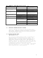
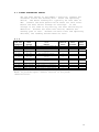
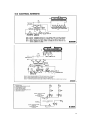
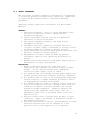
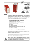
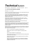
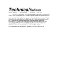
MICRO WELD
MODEL H & HX
BUTT WELDERS
MICRO PRODUCTS COMPANY
SERVICE MANUAL
1
TABLE OF CONTENTS
1.0
2.0
3.0
4.0
5.0
6.0
7.0
8.0
9.0
10.0
11.0
12.0
13.0
1.0
SPECIFICATIONS
GENERAL OPERATING INSTRUCTIONS
BASIC OPERATING PARTS
BASIC OPERATING PARTS LOCATION
TYPICAL OPERATING SEQUENCE
SPECIAL ADJUSTMENTS
PREVENTIVE MAINTENACE
SUGGESTED SETTINGS
DIAGNOISTIC CHART FOR TROULBE-SHOOTING
ELECTRICAL SCHEMATIC
SAFETY REMINDERS
BUYERS GUIDE
PARTS LIST
SPECIFICATIONS
Type of Welding Process
Welding Range
Material Suitability
Standard Operating Voltages
Maximum Line Demand 460 Volt
Maximum Line Demand 230 Volt
Single Phase AC Transformer
Clamp Method
Upset Method
Mounting
MODEL H
Butt Weld
.125 to .625
Steel Rod
460/230 Volts
25amps@100% duty cycle
79amps@10% duty cycle
50amps@100% duty cycle
158amps@10% duty cycle
16 KVA @ 50% duty cycle
Pneumatic, Foot Controlled
Pneumatic, Adjustable
4-Caster Wheels
MODEL HX
Butt Weld
.125 to .750
Steel Rod
460/230 Volts
42 amps@100% duty cycle
133 amps@10% duty cycle
84 amps@100% duty cycle
266 amps@10% duty cycle
27 KVA @ 50% duty cycle
Pneumatic, Foot Controlled
Pneumatic, Adjustable
4-Caster Wheels
Dimensions and Weights
Height Overall
Floor or Bench space
Welding Die Height
Weight
46”-Truck
39” x 29” Truck Type
41” – Truck Type
560 LBS – Truck Type
FEATURES
•
•
•
•
•
•
•
•
Micro Weld quality and workmanship
Heavy-duty construction & components
East to operate controls
Low maintenance costs
Easy to set welding parameters
Safety electrical switch circuits
Heavy-duty weld heat selection switch
Sensitive straight slide movable headpiece assembly
2
2.0
GENERAL OPERATING INSTRUCIONS
2.1
ELECTRICAL HOOK-UP INSTRUCTIONS
First determine that available electrical service in your
plant corresponds to the nameplate rating located on welder
housing. Electrical wiring to welder must be of sufficient
size to deliver full ampere load with no appreciable loss
during weld cycle. The welder will not operate properly if
there is more than a 10% variation in the line voltage. In
general, the welder should be fused with a slow blow fuse
of the 100% duty cycle rating. The minimum power cable size
to the welder can be obtained by using this same current
rating.
Refer to National Electrical Code and local electrical
regulations for adequate power sizes; disconnect methods
and fusing guidelines.
Remember line voltages to the welding machine are
potentially dangerous should the power cords be damaged or
severed. The welding voltages at the welding dies will not
harm an operator since they do not exceed 10 volts.
2.2
SAFETY PRECAUTIONS
(See section 11.0)
2.2.1 ELECTRICAL
Maintain electrical cable to welder in good repair. Welder
must be grounded and connections securely tightened. Heat
Switch must not be changed to new position while a weld
cycle is in process. Disconnect electrical service before
serving welder – high voltages are located within the base
of the welder.
2.2.2 MECHANICAL
Operator while using welder must wear safety glasses. Keep
all safety guards on welders and use properly. Operators
must be instructed on basic operation of unit to prevent
injury. Check nameplate rating and keep within material
size range for each welder.
3
2.3
WATER HOOK-UP
(If so equipped)
It is important that if a welder is to be operated for an
extended period of time and heads heat up, water lines must
be connected to the welder. Connect hoses to inlet and
outlet provided at the back of the welder. Shut-off valve
should be installed in the inlet line and the hose from the
outlet should run to an open sight drain. Water should be
turned off when the welder is not in use.
2.4
AIR HOOK-UP
Set air regulators for form 20 to 80 lbs. A safety pop-off
valve will be activated when air gauge is set for over 100
lbs.
2.5
WELDING DIES
The dies and shoes supplied with the welder will handle
most size and material types within the range of the
welder. For new weld applications consult the factory for
special die and shoe sets.
3.0
BASIC OPERATING PARTS
3.1
WELD HEAT SELECTION SWITCH
Welding heat is selected by means of a heavy-duty tap
switch, either six (6) or twelve (12) steps of voltage.
The switch is located conveniently on the lower front of
the welder. Number one (1) indicates high heat; number six
(6) or twelve (12) indicates low welding heat. Other
numbers are equally graduated from high to low to allow
just the right amount of voltage for the weld operation.
The model H has a six (6) point heat switch and the Model
HX has a twelve (12) point heat switch,
4
3.2
HEAD SPACING MECHANISM
3.2.1 The open head space adjustment bolt and locking jam nut are
located on the upset cylinder mounting plate to the
immediate left front of the upset cylinder. The open space
scale also located on the front of the upset cylinder
mounting is a quick reference guide for determining the
amount of open space by lining up the pointer on the
movable head endplate with the graduations on the scale.
When the pointer is in line with no. O on the scale. There
is a .020” space between the inside of the welding dies.
There is an increase of 1/4” spacing between the dies for
each graduation on the scale.
3.2.2 The closed head stop bolt and locking jam nut are located
in the movable head endplate in line with the open spaceadjusting bolt. The closed space stop should be adjusted
so that there is never less than .020” spacing between the
dies. The minimum .020” spacing must be maintained as an
electrical safety feature otherwise damage will occur to
the machine.
3.3
LIMIT SWITCH
The weld limit switch controls the cut-off point of current
flow to the welding dies. Limit switch adjustment is made
by moving the switch-initiating barrel, along the threaded
stud mounted in the movable headpiece. (See section 8 for
suggested settings).
3.4
WELDING DIES
The welding dies (lower and upper die shoes), serve three
purposes: (1) to carry current for welding, (2) to align
two ends of stock, and (3) to prevent material slippage
during a weld cycle. Small rod is placed in the smaller
grooves and the larger rod is placed in the bigger grooves.
3.5
THE OPERATING LEVER
The welder-operating lever is located at the top of the
regulator housing, located on the right end of the welder
truck. Keep hands away from clamp arms and headpiece when
operating the lever. The lever must be depressed the
entire ay when welding. The first part of the lever
movement allows the air from the top regulator to pass to
the air-upset cylinder. This makes firm contact between
the ends of the stock to be welded. At the bottom of the
operating lever movement, the lever initiates the weld
switch, which starts the weld.
5
3.6
CLAMP ARMS
The clamp arms are air operated. The foot controlled air
valves are used to initiate the air clamp cylinders. The
foot valves are located at the bottom of the welder
housing. The right foot pedal operates the right clamp
arm, and the left pedal operates the left clamp arm. To
clamp stock, place it in the proper welding die groove and
press the top edges of the tilt pedal on foot valve. To
release stock, press on bottom edge of foot valve tilt
pedal. Caution: care must be used when clamping stock, be
sure hands are clear of clamp arms.
3.7
ANNEAL SWITCH
The anneal switch is located directly above operating
lever, it is also known as the weld switch. When annealing
make sure to depress the anneal switch only. (See typical
anneal sequence)
6
4.0
BASIC OPERATING PARTS LOCATION
7
5.0
TYPICAL OPERATING SEQUENCE
All insulating materials must be removed from conductors
where they contact lower welding dies.
5.1
Set weld heat selection switch to recommended chart
setting.
5.2
Set upset pressure to recommended chart setting (PSI).
5.3
Adjust the head open space to proper chart setting.
5.4
Place the stock into welding dies so wire ends meet midway
between each die. Clamp into position with foot valve
pedals.
5.5
Lower the flash guard and raise up on the operating lever
until it initiates the operation switch, hold for 1 to 3
seconds to assure a complete weld cycle.
5.6
Unclamp welded conductors.
5.7
Trim off weld burr so welded area is equal to parent
material diameter. Incomplete burr removal or undercutting
of the weld area will result in subsequent weld breaks.
5.8
Typical anneal operating. The stock should be clamped in
the anneal clamps with the weld midway between the clamps.
Reach above the operating lever and press the weld/anneal
switch only. The switch should be jogged on and off to
allow the heat to spread out in the stock. Heat the stock
to the proper anneal temperature and allow to cool to where
there is no color before removing the weld burr. The
temperature required for annealing should be slightly above
the critical point which varies for different steels. Low
carbon steel (1008-1018) should be annealed at about 1650
degrees F., and mild to high carbon steel (1018-1090) at
about 1400 degrees to 1500 degrees F. This temperature
should be maintained just long enough to heat the weld zone
evenly.
DEGREES FARENGIHT
750 degrees
975 degrees
1290 degrees
1470 degrees
1650 degrees
1830 degrees
TEMPERATURE BY COLOR
Red heat, visible in the darkness
Red heat, visible in the daylight
Dark red
Dull cherry red
Cherry red
Bright cherry red (too hot)
Note: The critical temperature is quickly identified by the loss
of the steel’s magnetic properties.
8
6.0
SPECIAL ADJUSTMENTS
Model H, HX
Refer to section 8.0 for approximate settings.
6.1
WELD HEAT SELECTION
The weld heat selection switch is set simply by rotating
the handle with pointer to the number of heat required to
make a good weld.
6.2
HEAD SPACING
The closed head stop once set should never need changing.
This set to keep the weld dies from hitting each other when
upset is activated without stock being clamped in the dies.
To make this adjustment turn the air upset regulator to 10
PSI, with the flash guard in the up position lift up on the
upset lever to move movable headpiece, now check space
between dies, the space should be .020” then loosen the
locknut on the closed stop bolt and adjust until the space
is correct. Now retighten the locknut.
After adjusting the closed space, the open space can be
adjusted to the proper setting for the stock to be welded.
Use the open space scale when referring to actual setting.
6.3
LIMIT SWITCH
Loosening the lock nut then turning the tapered adjusting
nut to the correct setting makes the limit switch
adjustment. Clockwise will turn current off earlier,
counterclockwise will turn the current off later. This
setting can be used to lessen the amount of weld burr. By
adjusting the limit switch to lessen the weld burr,
decreased weld quality could result.
6.4
MODEL HX BURN-OFF INSTRUCTIONS
If unit is water-cooled and rate of burn off is high, unit
will require the water-cooling to prevent overheating of
the dies and headpiece. Connect the input line to one end
of water cool circuit. This input line should have a
shutoff valve so that water supply can be cut off when not
in operation. This will present condensation on headpiece,
which could cause transformer burn out. Water output hose
should be open – this will allow testing of water
temperature. During operation, flow should be adjusted so
that output feels warm to hand. This will minimize
condensation.
9
The hand knob at right hand end of truck adjusts the space
between the clamping jaws of dies. See setting chart at
end of instructions for approximate burn-off settings.
Operating switch is located in aluminum housing at the end
of the welder truck. Switch is located at top with switch
plunger extending down.
Clamp arms are air operated. The foot-operated valves are
located at the bottom of welder housing.
Caution: Care must be used when clamping stock, be sure
hands are clear of clamping dies before operating foot
valves.
Sequence of operation:
1. Set weld heat and die spacing per chart
2. Clamp stock in jaws
3. Press and hold operating switch till stock between jaws
melts and is blown away.
Note: Some cables have filler cord with an asphalt
impregnation. The asphalt will melt and run into the jaw
grooves. Jaw grooves must be kept clean, also the
connection between the jaw and jaw seat so that good
electrical connection is maintained.
Stranded Material
Size
5/8” diameter
3/8” diameter
5/16” diameter
1/4” diameter
Heat
6 or 7
9
9
9
Space
1/8” to 1/4”
1/8”
1/8”
1/8”
Clamp
Pressure
80 PSI
80 PSI
80 PSI
80 PSI
Note: Use wire brush to remove zinc oxides and beads from die and
shoe grooves. Because of thick zinc coating this cleaning of
grooves should be done often to allow good electrical contact
between dies and stock.
10
7.0
PREVENTIVE MAINTENANCE TECHNIQUE
Keep in Mind that these welders are precision built to last
many years, but will require good maintenance procedures.
They are designed to be as automatic as possible with a
minimum dependence on the ability of the operator.
Adjustments must be made by those thoroughly familiar with
the operating principles of the welders.
7.1 WELDING DIE NOTES
7.1.1 Welding dies and die shoes in poor condition are the
primary caused of bad welds.
7.1.2 Check die sets for excessive wear and replace if necessary.
7.1.3 Clean weld die bottoms to remove oxides with emery cloth
placed on a flat surface.
7.1.4 Clean die seats with emery cloth to brighten contact areas.
7.1.5 After cleaning of dies be sure to wipe off with soft clean
cloth.
7.1.6 Completely tighten dies into seats to assure a good
contact.
7.1.7 Worn die shoes will not hold stock during a weld cycle,
change steel faces or replace complete shoes.
7.2 WEEKLY
7.2.1 Tighten all loose parts.
7.2.2 Check for water leaks (if applicable).
7.2.3 Check for air leaks.
7.2.4 Drain airline filter bowls.
7.2.5 Tighten all loose parts.
7.3 QUARTERLY
7.3.1 Repeat above service items.
7.3.2 Check grease requirements on clamp arms pivot shafts and
lubrication points.
7.3.3 Check anneal parts and replace all worn or broken
assemblies
7.3.4 Check contacts on magnetic contactor for worn contacts.
7.3.5 Clean heat switch contacts with low residue cleaner and
recoat with petroleum jelly.
7.4 ANNUALLY
7.4.1 Repeat previously noted items.
7.4.2 Check for wear in clap arm pivots.
7.4.3 Clean inside and outside of welder.
7.4.4 Check grease requirements on headpiece slide shafts, grease
lightly.
7.4.5 Caution: make sure that power supply is disconnected before
servicing welder in anyway!
11
7.5
WELDING DIES AND DIE SHOES INFORMATION
Description:
Welding dies – Lower conducting electrode and clamp jaw.
Welding die shoes – Upper clamping member.
Welding dies and die shoes in poor condition are the main
causes of bad welds.
Care of die sets:
7.5.1 Use a brass or fiber blade to remove particles of flashings
that build-up on die sets. Excessive flash build-up causes
die burns on material and shorting of die sets.
7.5.2 Do not attempt to clamp material that is not suited for
welder into die sets. Undersize materials will slip and
burn die grooves, oversize materials will overstress
clamping parts.
7.5.3 Do not use welding die sets for a vise.
not withstand the mechanical abuse.
These parts will
7.5.4 Whenever welding dies are replaced, clean bottoms of dies
and corresponding die seats to a bright and clean condition
before bolting them tightly into place. An oxidized
surface will insulate the welding dies and reduce effective
welding voltage.
7.5.5 Welding die set will wear with use and must be changed
occasionally for good welding results. Keep and adequate
supply of replacement parts available. Wire and rod
slippage is a problem caused by poor die sets and a major
cause of wire breaks.
12
13
9.0
DIAGNOSTIC CHART FOR TROUBLE-SHOOTING
WELDING ACTION
Weld action normal but weld
burr doesn’t extend beyond
wire
Molten metal is blown out
and ends not joined
Weld has complete burr but
is dry and breaks off below
surface of wire
Welds good but poorly
aligned
Ends of wire buckle and may
not weld
Varying weld results
CAUSE
Lack of spacing
Weld heat too high
Stock is too small
Low upset pressure
Upset pressure too great
High carbon steel wire
Welding dies & die shoes
Starting space
Loose head shafts
Upset pressure too great
Low weld heat
Stock slipping
Varying weld voltages
Rod condition variations
Dies and die shoes
Flashings
9.1
REMEDY
Increase starting space
until desired burr is
obtained
Lower heat settings
Check size rating of welder
Adjust upset air regulator
Lower upset pressure
Carbon-steel wire often
appears like this, process
wire by annealing weld
before removing burr
Replace worn dies and shoes
Decrease starting space
Return heads to factory
Decrease upset pressure
Increase weld heat
Increase clamp air pressure
Check electric lines
Clean and tighten
transformer connections to
heads
Clean rod where clamped in
dies
Replace die shoes
Clean build-up of flash
materials
ELECTRICAL TROUBLE-SHOOTING OF WELDER
(Caution!! Extreme care should be exercised when making
these tests. Dangerous voltages are present in the welder.
Only persons familiar with electrical safety precautions
should perform these tests.)
9.1.1 TROUBLE-SHOOTING TABLE
(See section 9.1.3)
This electrical trouble-shooting table is furnished as a
suggested method of trouble-shooting the welder. The
individual steps of the table should be performed in the
order given, to make the tests valid. The electrical
schematic (section 10) furnished for these tests show the
table test points. The table may be used for welders with
a different but closely related wiring by using
corresponding test points. During all tests, line voltage
should be connected to L1 & L2 of the welder. The heat
switch should be set to the #1 position.
14
9.1.2 FINAL ELECTRICAL CHECKS
Set the heat switch to the number 1 position, connect the
voltmeter across the welding dies. Press the operating
switch. The meter reading will typically be less than 10
VAC. Consult the weld specification sheet for this value.
Rotate the heat switch through all settings. If the
voltage is not read at any setting, the heat switch may be
defective. Actuate the weld limit switch; observe the
reading goes to zero. Release the weld limit and operating
switches, the reading should remain at zero.
9.1.3
TEST LEAD
CONNECTION
X1 X2
X2 FU1-1
X2 FU1-2
METER
READING
115 VAC
115 VAC
115 VAC
X2 LS1-1
X2 LS1-2
115 VAC
115 VAC
X2 LS2-1
X2 LS2-2
115 VAC
115 VAC
X2
X2
L2
L2
L1
LS3-1
LS3-2
CR1-1
CR1-2
S1-1
115 VAC
115 VAC
Line voltage
Line voltage
Line voltage
PROBLEM
IF NO
READING
Bad control transformer(T1)
Bad fuse connection
Open fuse
Open wire to operating
switch
Bad operating switch
Open wire to flash guard
switch
Open flash guard switch
Open wire to weld limit
switch
Bad weld limit switch
Open wiring to contactor
Bad contactor
Open wire to head switch
PRESS
OPERATING
SWITCH
WELD LIMIT
SWITCH
ACCTUATED
PRESS
ANNEAL
SWITCH
X
X
X
X
X
X
X
NOTE: To perform repair consult section 13 for parts
identification.
15
16
11.0 SAFETY REMINDERS
The following accident prevention information is presented
to eliminate potential hazards while operating, inspecting
or repairing Micro-Weld electric resistance welding
equipment.
Important safety compliance information for Micro-Weld
Welders.
GENERAL
1. Qualified personnel, prior to using equipment, must
instruct an operator on basic operation and
malfunction methods.
2. Safety eyeglasses must be worn by all personnel
operating or servicing welders.
3. Use safety equipment properly and keep safety
equipment on welders.
4. Determine that both operating voltages and hertz
(cycles) of power supply correspond to ratings listed
on welder nameplate located on welder housing.
5. Check nameplate ratings and keep within capacities and
material categories stated therein.
6. Adjustments or repairs must be made by persons
thoroughly familiar with operating principles of
welder.
7. Welder must be disconnected from power supply prior to
maintenance or repair procedures.
ELECTRICAL
1. Refer to National Electrical Code and local
regulations for adequate electrical wiring to power
welder. Do not operate welder with inadequate
electrical power supply cords or cable.
2. All welders must be grounded through power supply and
welder ground connection terminal securely tightened.
3. All welders must be able to be disconnected from power
source either by a double breaking disconnect switch
or unplugged by standard rated plugs.
4. All welders must be fused to prevent injury should an
electrical malfunction occur. Welders must never be
fused for an ampere load that exceeds the ratings
stated on welder nameplate. Normally welders are
fused using the nameplate rated load; time lag
parameters functional to standard fuses allow this
specification.
5. Electric power cords to welder must be kept in good
condition. Report any damage or potential hazards to
maintenance personnel.
6. The weld heat selection switch, potentiometer or range
selection devices must not be changed to a new
position while a weld operation is in process.
17
12.0 BUYERS GUIDE
HOW TO ORDER PARTS:
You must provide
1. Machine Model
2. Machine Serial Number
3. Voltage
Then identify part(s) on part list (last page in book) and
provide MICRO with the circled number.
CALL MICRO at 800-872-1068
OR FAX MICRO at 630-787-9360
Provide MICRO with your company name and purchase order
number.
18
13.0 PARTS LIST
19
20
21
22
PARTS LIST
H, HX SERIES BUTT WELDERS
MODEL/
PART NO.
DESCRIPTION
ITEM #
H-01A
H-01B
H-03
H-03A
H-03B
H-04
H-05
H-06
H-07
H-08L
H-08R
H-09
H-10
H-11
H-12
H-13
H-14
H-15
H-16
H-17
H-18
H-19
H-19A
H-20
H-21
H-22
H-23
H-23A
H-24
H-25
H-26
H-27
H-30
H-31
H-32
H-33
H-34
H-35
H-36
H-37
H-37C
H-39
H-41
H-41A
Basic head match machined
Complete head assembly
Flash guard assembly
Flash guard mount screw
Flash guard switch
Shaft shield
Shaft shield mount screw
Outer clamp arm pin washer
Inner clamp arm pin washer
Clamp arm, left
Clamp arm, right
Clamp arm pivot pin
Outer arm pin bolt
Inner arm pin screw
Stat. Head mount bolt, rear
Stat. Head mount bolt front, left
Stat. Head mount bolt front, right
Secondary mount bolts, movable
Secondary mount bolts, stationary
Secondary clamp plate, stat. Head
Head return spring, mov. head
End plate, movable head
Limit switch scale screw
End plate mount bolt
Grease fitting 90 degrees
Grease fitting, straight
Closed head stop bolt
Closed head stop nut
Clamp cylinder #20
Cylinder shaft protecting boot
Cylinder diaphragm #20
Hose fitting, brass
Insulating plate, upset frame
Insulating washers & tubes
Steel washers, upset frame
Upset frame mount screws
Open head stop bolt & nut
Open space scale
Scale mount screws
Limit switch, roller type
Limit switch cover
Limit switch mount screws
Limit switch actuator nut
Actuator nut locknut
31054
31055
31056
90258
57813
31014
90821
31546
31006
31017
31030
31000
90258
90811
90657
90663
90664
90509
90659
51000
80056
41076
31009
90260
48422
48423
90327
92106
77703
77715
77710
94302
41002
31061
92751
90260
90329
41005
91048
57811
51001
91048
31008
31007
23
PARTS LIST
H, HX SERIES BUTT WELDERS
MODEL/
PART NO.
H-42
H-43
H-44
H-46
H-47
H-48
H-49
H-50
H-51
H-52
H-55
H-57
H-58
H-58R
H-59
H-60
H-60L
H-60R
H-61
H-61L
H-61R
H-61S
H-62
HX-68
HX-68A
H-70
H-71
H-72
H&HX-72
HX-72
H-72A
H-74
H-75
HX-76
HX-77
HX-78
HX-79
H-80
H-81
H-82W
H-85
HX-97
H-98
H-104
H-109
DESCRIPTION
ITEM #
Cylinder shaft boot #12
Rotochamber #12, upset
Cylinder diaphragm #12
Weld transformer, state voltage & S/N
Transformer primary coil, state voltage
& S/N
Transformer secondary, state voltage & S/N
Transformer support strap
Transformer ring
¾” transformer stud
½” transformer stud
Upset cylinder mount plate
Die mount bolt
V-groove dies, copper
Radius groove die set
Shoe mount washers
Shoe set w/inserts
Steel shoe, left
Steel shoe, right
Set of inserts, 4 pcs.
Steel insert, for left shoe
Steel insert, for right shoe
Steel insert, straight
Insert mount screw
Auto transformer
Primary coil, auto transformer
6 pt. Heat switch
Heat switch mount bolts
Weld contactor 440V
Weld contactor 240V
Weld contactor 240V
Contactor repair kit
Terminal block
Terminal block mount screws
12 point heat switch
Weld transformer, 2 tap
2 tap primary
Secondary
Complete truck
Swivel caster
Wheel only
Truck door
Foot pedal muffler
Foot pedal
#4 shear
Vise, standard
77715
77700
77708
51008
53037
51011
33291
51002
51005
90301
41003
90660
31020
31042
92753
31053
31001
31002
31052
31004
31005
31003
90704
51019
51018
56549
90294
57609
57610
57611
57625
53000
90204
56547
53047
51027
51026
41096
48108
spcl.
41014
77892
77859
64009
78112
24
PARTS LIST
H, HX SERIES BUTT WELDERS
MODEL/
PART NO.
DESCRIPTION
ITEM #
HX-109A
H-110
HX-110
HX-110A
H-111
H-114
H-115
H-116
H-117
H-118
H-119
H-120
H-122
H-123
H-125
H-125A
H-126
Heavy duty vise
Vise bracket
Vise bracket
Heavy duty vise bracket
Vise mount bolt
#4 shear blades
Anneal bracket, CA
Anneal bracket mount screw
CA anneal clamps, pair
Anneal mount bolts, CA
Anneal bracket, CAL
CAL anneal clamps, pair
Anneal mount bolts, CAL
Clamp arm flow control valve
Control step-down
Fuse block
Heavy duty step-down
78111
60022
60004
60005
90262
78204
62085
90509
62096
90258
62085
62020
90258
77862
57601
58119
59523
H-A19
Complete air frame assembly
59511
25