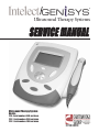
1
®
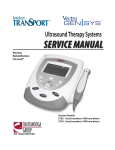
Ultrasound Therapy Systems
SERVICE MANUAL
Ultrasound Therapy System
Models:
2776 - Serial numbers 1000 and above
2782 - Serial numbers 1000 and above
2792 - Serial numbers 1000 and above
ISO 13485 CERTIFIED
TABLE of CONTENTS
Intelect®/Genisys® Ultrasound Therapy Systems
Foreword . . . . . . . . . . . . . . . . . . . . . . . . . . . . . . . . . . . . . . . . . .1
1- Safety Precautions . . . . . . . . . . . . . . . . . . . . . . . . . . . . . . . .2
2- Theory of Operation . . . . . . . . . . . . . . . . . . . . . . . . . . . . . . .3
3- Nomenclature . . . . . . . . . . . . . . . . . . . . . . . . . . . . . . . . . . .4-5
Intelect/Genisys Ultrasound Therapy System . . . . . . . . . . . . .4
Intelect/Genisys Ultrasound Symbol Definitions . . . . . . . . . . .5
4- Specifications . . . . . . . . . . . . . . . . . . . . . . . . . . . . . . . . . . . .6
5- Troubleshooting . . . . . . . . . . . . . . . . . . . . . . . . . . . . . . . .7-14
5.1 Intelect/Genisys Ultrasound Software Error Messages .7-9
5.2 Intelect/Genisys Ultrasound Diagnostics . . . . . . . . . . . .10
5.3 Visual Inspection . . . . . . . . . . . . . . . . . . . . . . . . . . . . . . .11
5.4 Leakage Tests . . . . . . . . . . . . . . . . . . . . . . . . . . . . . . . . .11
5.5 Unit Startop and Fan Testing . . . . . . . . . . . . . . . . . . . . .11
5.6 Ultrasound Tests . . . . . . . . . . . . . . . . . . . . . . . . . . . . . . .12
5.7 Ultrasound Applicator Identification Test . . . . . . . . . . . . .12
5.8 Ultrasound Applicator Output Test . . . . . . . . . . . . . . . . .13
5.9 Ultrasound Duty Cycle Test . . . . . . . . . . . . . . . . . . . . . .14
6- Removal & Replacement . . . . . . . . . . . . . . . . . . . . . . . .15-20
6.1 General . . . . . . . . . . . . . . . . . . . . . . . . . . . . . . . . . . . . . .15
6.2 Top & Bottom of Unit . . . . . . . . . . . . . . . . . . . . . . . . . . . .15
6.3 Fan Removal & Replacement . . . . . . . . . . . . . . . . . . . . .16
6.4 Power Supply Removal & Replacement . . . . . . . . . . . . .17
6.5 Ultrasound Board Removal & Replacement . . . . . . . . . .18
6.6 LCD Display Removal & Replacement . . . . . . . . . . . . . .19
6.7 Control Board Removal & Repalcement . . . . . . . . . . . . .20
7- Ultrasound Applicator Calibration . . . . . . . . . . . . . . . . . .21
8- Parts . . . . . . . . . . . . . . . . . . . . . . . . . . . . . . . . . . . . . . . .22-27
9- Schematics . . . . . . . . . . . . . . . . . . . . . . . . . . . . . . . . . . .28-33
10- Warranty . . . . . . . . . . . . . . . . . . . . . . . . . . . . . . . . . . . . . . .34
©2004 Encore Medical Corporation or its affiliates, Austin, Texas, USA. Any use of editorial, pictorial or layout composition of this publication without express written consent
from the Chattanooga Group of Encore Medical, L.P. is strictly prohibited. This publication was written, illustrated and prepared for print by the Chattanooga Group of Encore
Medical, L.P.
FOREWORD
Intelect®/Genisys® Ultrasound Therapy Systems
Read, understand and follow the Safety Precautions and information contained in this manual.
This manual contains the necessary safety, and field service information for those Field Service Technicians,
approved by Chattanooga Group, to perform field service on the Intelect/Genisys Ultrasound Therapy Systems.
At the time of publication the information contained herein was current and up to date. However, due to
continual technological improvements and increased clinical knowledge in the field of electrotherapy, as well as
Chattanooga Group’s policy of continual improvement, Chattanooga Group reserves the right to make periodic
changes and improvements to their equipment and documentation without any obligation on the part of
Chattanooga Group.
It is the sole responsibility of field technicians to stay informed and trained in the latest technology utilized in
the Intelect/Genisys Ultrasound Therapy Systems by Chattanooga Group. From time to time, as significant
improvements are incorporated, Service Bulletins will be produced and made available on our web site
(www.chattgroup.com) in lieu of reprinting a complete manual prematurely. These Service Bulletins will provide
updated service information and technology improvements to the Intelect/Genisys Ultrasound Therapy Systems
for use by certified service technicians.
“Certified Service Technician” Definitions;
1. Level I- Those Field Service Technicians that have successfully completed the minimal training required by
Chattanooga Group in basic service techniques.
2. Level II- Those Field Service Technicians that have successfully completed Level I Training as well as
Level II training as required to perform specific troubleshooting and repair techniques and
procedures.
3. Level III- Those Field Service Technicians that have successfully completed Levels I & II Training as well as
Level III Advanced Training as required to perform all necessary Troubleshooting and Repair
techniques. The Technician having successfully completed the three levels of training and coupled
with experience should have the ability to train other technicians in Level I and Level II Training
with the necessary Training Materials from Chattanooga Group.
4. Temporary- Chattanooga Group, at its discretion and based on known experience of the technician, may
grant a “Temporary Certification” to a field technician for particular troubleshooting and repair
of a specific system requiring immediate attention. This “Temporary Certification” in no fashion
acknowledges the training level of a technician as defined above. This “Temporary
Certification” is utilized only in unique situations for a specific unit for a specific service
technique only and is documented as such.
Due to the complex nature of the technology utilized by Chattanooga Group, the recommended troubleshooting
techniques are to determine “Bad Board” and board replacement only. No board component level
troubleshooting is recommended nor will information or parts be supplied by Chattanooga Group. Any board
component level troubleshooting performed will be at sole risk and liability of the Service Technician
performing such troubleshooting techniques.
This equipment is to be used only under the prescription and supervision of a licensed medical practitioner.
This equipment is to be serviced only by a “Certified Service Technician”.
1
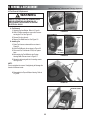
1- SAFETY PRECAUTIONS
Intelect®/Genisys® Ultrasound Therapy Systems
1.2 Safety Precautions
Read, understand and follow all safety precautions
found in this manual. Below are general safety
precautions that must be read and understood before
attempting any service techniques on these units.
Throughout this manual specific safety precautions will
be found. Read, understand and follow all safety
precautions.
1.1 Precautionary Symbol Definitions
The precautionary instructions found in this manual are
indicated by specific symbols. Understand these
symbols and their definitions before operating or
servicing this equipment. The definitions of
these symbols are as follows;
A. CAUTION
!
CAUTION
!
Text with a “CAUTION” indicator will explain
possible safety infractions that have the potential to
cause minor to moderate injury or damage to
equipment.
• Read, understand and practice the precautionary
and operating instructions. Know the limitations
and hazards associated with using any ultrasound
device. Observe the precautionary and operational
decals placed on the unit.
• DO NOT operate the Intelect or Genisys when
connected to any unit other than Chattanooga
Group devices. Do not operate the unit in an
environment of short-wave diathermy use.
• The Ultrasound modality should be routinely
checked before each use to determine that all
controls function normally; especially that the
intensity control does properly adjust the intensity
of the ultrasonic power output in a stable manner.
Also, determine that the treatment time control
does actually terminate ultrasonic power output
when the timer reaches zero.
• Use of controls or adjustments or performance of
procedures other than those specified herein may
result in hazardous exposure to ultrasonic energy.
• DO NOT use sharp objects such as a pencil point
or ballpoint pen to operate the buttons on the
control panel as damage may result.
• Operate, transport and store this unit in
temperatures between 59 °F and 104 °F (15 °C
and 40 °C), with Relative Humidity ranging from
30%- 60%.
• Inappropriate handling of, and subjecting the
ultrasound applicator to physical abuse, may
adversely affect its characteristics.
• Inspect Sound Head for cracks, which may allow
the ingress of conductive fluid before each use.
• Inspect all cables, leads and associated
connectors before each use.
B. WARNING
!
CAUTION
WARNING
Text with a “WARNING” indicator will explain
possible safety infractions that will potentially cause
serious injury and equipment damage.
C. DANGER
! DANGER
Text with a “DANGER” indicator will explain
possible safety infractions that are imminently
hazardous situations that would result in death or
serious injury.
D. EXPLOSION HAZARD
Do not use this equipment in the presence
of flammable anesthetics. This symbol is
also prominently displayed on the serial
number plate of the unit.
E. DANGEROUS VOLTAGE
Text with a “Dangerous Voltage” indicator serves to
inform the Service Technician of possible hazards
resulting in the electrical charge retained by faulty
power supplies.
F. CORROSIVE HAZARD (NiMH Battery)
Text with a “Corrosive Hazard” indicator
will explain possible safety infractions if the
chemical components of this product are
exposed to air, skin or other materials.
G. NOTE:
Throughout this manual “NOTE” may be found.
The Notes are helpful information to aid in the
particular area or function being described.
2
2- THEORY of OPERATION
Intelect®/Genisys® Ultrasound Therapy Systems
2.1 Overview
The Intelect/Genisys Ultrasound Therapy Systems are comprised of several PC board assemblies housed within a
common enclosure. These assemblies each support a distinct function in the product. The basic elements are User
Interface, Control Board, Ultrasound Board, Ultrasound Applicator, and Power Supply Circuits.
2.2 Power Supply Circuits
A universal input power supply provides all parts of the system with 12 volts DC. The supply is connected to the mains
at all times when the cord is attached. The power switch on the top of the unit, switch the 12V output of the power
supply to the different components in the system by way of the Power Distribution Board. The 12V supply is regulated
locally at each PC board as required.
2.3 Control Board
The Control Board serves just as its name implies. It controls the operation of the ultrasound board, user interface and
optional accessories. The control board communicates to the ultrasound board through a proprietary 8-bit parallel bus.
The control board drives the display. The control board reads the menu buttons. The control board also reads the
amplitude and the contrast control on the system. Sound output is generated by the control board and routed to an
internal speaker.
2.4 Ultrasound Board and Applicator
The ultrasound board generates the 1 or 3.3 MHz output to drive the ultrasound Sound Head. The ultrasound
board is accessed much like an I/O port by the control board. It can provide current and voltage information
about the ultrasound output of the board. The calibration data for the Sound Head is passed through the
ultrasound board from the applicator up to the control board. By storing the calibration data in the applicator
there is no calibration necessary for the ultrasound board. Calibrated Chattanooga Group Ultrasound Applicators,
designed specifically for the Intelect/Genisys Ultrasound Therapy Systems, can be connected and operated to
provide accurate coupling and output.
2.5 User Interface and Accessories
The LCD display panel provides the operator visible feedback in the way of menu choices. Pressing the menu
buttons makes selections from the menus. The control board interprets these user inputs and responds
accordingly. Audible feedback is given as well for events such as keypresses and end of treatment.
The Optional Battery mounts in the system bottom and supplies 24 VDC to the power supply. The Power Supply
distributes the power required to the system as needed. The charging circuit for the battery is incorporated on the
Control PCB. An icon on the display reflects the available amount of charge in the battery. When the system is
connected to an approved power outlet and a battery is installed in the system, the system will charge the battery
to full capacity. The incorporated charger will not overcharge the battery.
3
3- NOMENCLATURE
Intelect®/Genisys® Ultrasound Therapy Systems
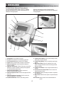
3.1 Intelect/Genisys Ultrasound Therapy System
The nomenclature graphics below, Figure 3.1, indicates
the general locations of the exterior components of the
Ultrasound Therapy System.
Know the components and their functions before
performing any operation on or service to the Ultrasound
Therapy System.
1
3
2
16
15
4
17
5
14
13
6
7
8
12
10
11
9
FIGURE 3.1
1.
2.
3.
4.
5.
On/Off Switch- Turns system On and Off.
Fan Grill- Allow exhaust of air circulated by system fan.
LCD Contrast Knob-Adjusts contrast of LCD Display.
Plynth- Allows for wall mounting or sitting on a flat surface.
Ultrasound Applicator- Used to administer Ultrasound
Therapy to patient.
6. Applicator LED Indicator- Flashes 5 times upon connecting
applicator to system. Illuminates constantly when applicator
is coupled to patient treatment area.
7. Ultrasound Intensity Button- Used to increase and
decrease ultrasound output intensity.
8. Ultrasound Applicator Hook- Used to store applicator when
not in use.
9. Ultrasound Applicator Connector- Used to connect the
Ultrasound Applicators to the System
10. Treatment Start Button- Press to start therapy session.
11. Treatment Pause Button- Press to pause therapy session.
Press again to continue session.
12. Treatment Stop Button- Press to completely stop therapy
session.
13. Multi-Control Button- Press the respective icon on this
button to change parameters and to scroll through Clinical
Resources Library
14. Treatment Time Button- Press to adjust treatment time up
or down.
15. Clinical Resources Library Button- Press to access the
Clinical Resources Library.
16. LCD Display- Displays necessary information for operation
and maintenance.
17. Mains Power Cord- Connects system to required electrical
outlet.
Not Illustrated- Battery Access Cover located beneath the
plynth.
4
3- NOMENCLATURE
Intelect®/Genisys® Ultrasound Therapy Systems
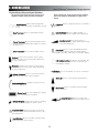
3.2 Intelect/Genisys Ultrasound Symbol Definitions
The graphic symbols listed below can be found on the
Ultrasound Therapy System and within the software.
Become familiar with these symbols and their definitions
prior to any operation, mainteneance or repairs of the
system.
Frequency Press to change frequency to 3.3 MHz or
1MHz
On/Off Switch- Flashes when plugged into
power outlet. Illuminates steady when system
is On
Intensity Display- Press to display “Watts” or
“Watts per cm2“ for the output of the ultrasound.
Stop Treatment- Press to stop therapy session.
Intensity Control- Press the Increase or
Decrease symbol to adjust ultrasound intensity
to the prescribed level.
Pause Treatment- Press to pause therapy session
and retain time remaining. Press again to continue
therapy session
Duty Cycle- Press to select and display the Duty
Cycle of the Ultrasound as prescribed. Options
avaliable are: 10%, 20%, 50, or Continuous (100%).
Start Treatment- Press to start therapy session
Increase- Found in two locations on the system,
press to increase session time and/or ultrasound
intensity respectively.
LCD Display Contrast- Located on the Fan Grill, this
indicates the control to increase or decrease the
LCD Display contrast.
Decrease- Found in two locations on the system,
press to decrease session time and/or ultrasound
intensity respectively.
Back- Press to return back one screen on the LCD
Display.
Clinical Resources- Press to access the Clinical
Resourses area of the system software.
Scroll Up- Press to scroll up when making menu
selections
Ultrasound Applicator- Indicates connector for the
ultrasound applicators.
Scroll Down- Press to scroll down when making
menu selections
Charge Level- This icon indicates the charge
level of the battery, if installed.
Accept & Return- Press to accept menu
selection and to return to the Home Screen
Battery Charging- Indicates the system is charging
the battery when plugged into power outlet.
Treatment Time- Press the Increase or Decrease
symbol to adjust ultrasound treatment time to the
prescribed level.
Head Warming- Press to turn Off or On the Head
Warming feature of the system.
5
4- SPECIFICATIONS
Intelect®/Genisys® Ultrasound Therapy Systems
B.Outputs
One Ultrasound Output
4.1 Intelect/Genisys Ultrasound Therapy System
Physical Specifications
C. Ultrasound Applicator Sizes Available
1. 1 cm2
2. 2 cm2
3. 5 cm2 (Standard)
4. 10 cm2
A. Dimensions
1. 28.8 cm (11.3”) Width
32.8 cm (12.9”) Depth
16.3 cm (6.4”) Height
2. 2.3 kg (5.07 lbs) with 5 cm2 Applicator and Plynth
3. Case Material: Polycarbonate Plastic
4. Optional Battery Weight: 0.85 kg (1.87 lbs)
D. Power Input Requirements
1. 100-240VAC, 50/60 Hz, 75W
4.2 Intelect/Genisys Ultrasound Specifications
Frequency . . . . . . . . . . . . . . . . . . . . . . . . . . . . . . . . . . . . . . . . . . . . . . . . . . . . . . . . . . . . . . . . . 1 MHz, +/- 5%; 3.3 Mhz, +/- 5%
Duty Cycles . . . . . . . . . . . . . . . . . . . . . . . . . . . . . . . . . . . . . . . . . . . . . . . . . . . . . . . . . . . . . . . . . . 10%, 20%, 50%, Continuous
Pulse Frequency . . . . . . . . . . . . . . . . . . . . . . . . . . . . . . . . . . . . . . . . . . . . . . . . . . . . . . . . . . . . . . . . . . . . . . . . . . . . . . . . 100Hz
Pulse Duration . . . . . . . . . . . . . . . . . . . . . . . . . . . . . . . . . . . . . . . . . . . . . . . . . . . . . . . . . . . . . . . . . . . . . . . . . . . 1mSec, +/-20%
2mSec, +/-20%
5mSec, +/-20%
Output Power
10cm2 Crystal . . . . . . . . . . . . . . . . . . . . . . . . . . . . . . . . . . . . . . . . . . . . . . . . . . . . . . . . . . . . . . . . . . . . . . . . 0-20 Watts at 1MHz
0-10 Watts at 3.3 MHz
5cm2 Crystal. . . . . . . . . . . . . . . . . . . . . . . . . . . . . . . . . . . . . . . . . . . . . . . . . . . . . . . . . . . . . . . . . . . . 0-10 Watts, 1 and 3.3 MHz
2cm2 Crystal. . . . . . . . . . . . . . . . . . . . . . . . . . . . . . . . . . . . . . . . . . . . . . . . . . . . . . . . . . . . . . . . . . . . . 0-4 Watts, 1 and 3.3 MHz
1cm2 Crystal . . . . . . . . . . . . . . . . . . . . . . . . . . . . . . . . . . . . . . . . . . . . . . . . . . . . . . . . . . . . . . . . . . . . . . 0-2 Watts 3.3 MHz Only
Amplitude . . . . . . . . . . . . . . . . . . . . . . . . . . . . . . . . . . . . . . . . . . . . . . . . . . . . . . . . . . . . . . . 0 to 2.5 w/cm2 in continuous mode,
. . . . . . . . . . . . . . . . . . . . . . . . . . . . . . . . . . . . . . . . . . . . . . . . . . . . . . . . . . . . . . . . . . . . . . . . . . . . . . 0-3 w/cm2 in pulsed modes
Output accuracy . . . . . . . . . . . . . . . . . . . . . . . . . . . . . . . . . . . . . . . . . . . . . . . . . . . . . . . . . . . . +/- 20% above 10% of maximum
Temporal Peak to Average Ratios: . . . . . . . . . . . . . . . . . . . . . . . . . . . . . . . . . . . . . . . . . . . . . . . 2:1, ± 20%, at 50% Duty Cycle
5:1, ± 20%, at 20% Duty Cycle
9:1, ± 20%, at 10% Duty Cycle
Beam Nonuniformity Ratio. . . . . . . . . . . . . . . . . . . . . . . . . . . . . . . . . . . . . . . . . . . . . . . . . . . . . . . . . . . . . . . . . 5.0 : 1 maximum
Beam Type . . . . . . . . . . . . . . . . . . . . . . . . . . . . . . . . . . . . . . . . . . . . . . . . . . . . . . . . . . . . . . . . . . . . . . . . . . . . . . . . . Collimating
Effective Radiating Areas. . . . . . . . . . . . . . . . . . . . . . . . . . . . . . . . . . . . . . . . . . . . . . . . . . . . . . . 10cm2 Crystal - 8.5cm2, +/- 1.5
. . . . . . . . . . . . . . . . . . . . . . . . . . . . . . . . . . . . . . . . . . . . . . . . . . . . . . . . . . . . . . . . . . . . . . . . . . . 5 cm2 Crystal - 4.0cm2, +/- 1.0
. . . . . . . . . . . . . . . . . . . . . . . . . . . . . . . . . . . . . . . . . . . . . . . . . . . . . . . . . . . . . . . . . . . . . . . . . . 2cm2 Crystal - 1.8cm2, +0.2/-0.4
. . . . . . . . . . . . . . . . . . . . . . . . . . . . . . . . . . . . . . . . . . . . . . . . . . . . . . . . . . . . . . . . . . . . . . . . . . 1cm2 Crystal - 0.8cm2, +0.2/-0.4
Treatment Time . . . . . . . . . . . . . . . . . . . . . . . . . . . . . . . . . . . . . . . . . . . . . . . . . . . . . . . . . . . . . . . . . . . . . . . . . . . . 1-60 Minutes
Ultrasound Head Warming Feature. . . . . . . . . . . 50% of maximum output until Crystal Temp reaches approx. 38 °C (100 °F)
then 10% of maximum or Off to maintain Temperature
6
5- TROUBLESHOOTING
Intelect®/Genisys® Ultrasound Therapy Systems
primarily user definable and remedied by following
the instructions given by the unit. Error meesages
in the ranges of 200- 299 and 300-399, require the
attention of a field technician certified by
Chattanooga Group in order to perform the
necessary diagnostics and properly replace any
necessary components.
5.1 Intelect/Genisys Ultrasound Software Error Messages
A. The information provided below is intended to aid in
defining the Software Error Messages of the Ultrasound
Therapy System. Once a particular Error Message is
defined the information will also list probable causes
and possible remedies. Once the problem area is
determined subsequent diagnostics for verification
will be necessary to determine “Bad Board”. All
diagnostic tests will be to validate a “Bad
Board” only. No component level troubleshooting
information is or will be provided by Chattanooga
Group for field troubleshooting of board components.
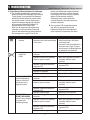
Error messages in the range of 100 to 199 are
CODE No.
100
101
B. Once a particular PCB has been determined as
bad, refer to the appropriate Removal and
Replacement Section for the board affected for
proper instructions for replacement of the board.
TYPE MESSAGE
Icon- Sound Head
overtemp
PROBABLE CAUSES
POSSIBLE REMEDIES
1. Sound Head has overheated to a
A. Turn Off Head Warming feature.
temperature that could cause damage B. Allow Sound Head to cool before
to the crystal.
continuing therapy.
C. Connect a known good Applicator to
the system and try again. If system
works properly, re-calibrate Applicator
or replace with new Applicator.
Icon- No applicator
plugged into
system
1. Applicator not plugged into system
connector.
A. Plug Applicator into system.
2. Applicator connector not completely
seated in system connector.
A. Make certain Applicator connector is
completely seated in system
connector.
3. Applicator Cable disconnected from
Applicator PCB.
A. Connect Applicator Cable to
Applicator PCB
4. Applicator cable damaged.
A. Replace with new Applicator.
5. Applicator not calibrated
A. Calibrate Applicator.
6. Bad Ultrasound Board
WARN_US_UNPLUGGED 1. Applicator not plugged into system
Technician attempted to
connector.
calibrate an ultrasound
2. Applicator connector not completely
applicator but none is
seated in system connector.
plugged into system.
A. Replace Ultrasound Board
A. Plug Applicator into system.
A. Make certain Applicator connector is
completely seated in system
connector.
3. Applicator Cable disconnected from
Applicator PCB.
A. Connect Applicator Cable to
Applicator PCB
4. Applicator cable damaged.
1. Applicator not plugged into system
connector.
A. Replace with new Applicator.
WARN_US_APPL_
BECAME_UNPLUGGED
Applicator came unplugged 2. Applicator connector not completely
from system while
seated in system connector.
administering therapy.
A. Plug Applicator into system.
3. Applicator Cable disconnected from
Applicator PCB.
A. Connect Applicator Cable to
Applicator PCB
4. Applicator cable damaged.
A. Replace with new Applicator.
7
A. Make certain Applicator connector is
completely seated in system
connector.
5- TROUBLESHOOTING
Intelect®/Genisys® Ultrasound Therapy Systems
5.1 Intelect/Genisys Software Error Messages (Continued)
CODE No.
TYPE MESSAGE
200
ERR_EEPROM
Error accessing the internal
EEPROM used to store
system configuration
settings and protocols.
ERR_APPL_SAVE_CAL_
DATA
Error attempting to save
data to applicator EEPROM
during applicator
calibration.
ERR_APPL_NOT_
CALLED_OK
General error attempting to
calibrate an applicator.
201
202
203
PROBABLE CAUSES
POSSIBLE REMEDIES
1. Bad Control Board
A. Replace Control Board.
1. Bad Applicator
A. Replace with known good Applicator.
2. Bad Applicator Cable
A. Replace with known good Applicator.
3. Applicator PCB Connector Bad
A. Replace Ultrasound Board.
4. Bad Ultrasound Board
A. Replace Ultrasound Board.
1. Bad Applicator
A. Replace with known good Applicator.
2. Bad Applicator Cable
A. Replace with known good Applicator.
3. Applicator PCB Connector Bad
A. Replace Ultrasound Board.
4. Bad Ultrasound Board
1. Bad Applicator
A. Replace Ultrasound Board.
A. Replace with known good Applicator.
ERR_APPL_SAVE_
TIMEOUT
2. Bad Applicator Cable
Error attempting to save
3. Applicator PCB Connector Bad
data to applicator EEPROM
during applicator calibration 4. Bad Ultrasound Board
8
A. Replace with known good Applicator.
A. Replace Ultrasound Board.
A. Replace Ultrasound Board.
5- TROUBLESHOOTING
Intelect®/Genisys® Ultrasound Therapy Systems
5.1 Intelect/Genisys Software Error Messages (Continued)
CODE No.
TYPE MESSAGE
PROBABLE CAUSES
300
CRIT_ERR_US_BOARD 1. Ultrasound Board to Control Board
Some type of critical
Connecting Header loose or
ultrasound board error has
disconnected.
occurred.
2. Bad Ultrasound Board.
3. Bad Control Board.
301
CRIT_ERR_US_BOARD_ 1. Ultrasound Board to Control Board
NOT_DETECTED
Connecting Header loose or
No ultrasound board is
disconnected.
detected in unit.
2. Bad Ultrasound Board.
3. Bad Control Board.
302
CRIT_ERR_US_RESET
1. Ultrasound Board to Control Board
Ultrasound board has reset
Connecting Header loose or
for some unknown reason.
disconnected.
2. Bad Ultrasound Board.
3. Bad Control Board.
303
CRIT_ERR_US_BOARD_ 1. Ultrasound Board to Control Board
READ
Connecting Header loose or
Error reading from
disconnected.
ultrasound board.
2. Bad Ultrasound Board.
3. Bad Control Board.
304
CRIT_ERR_US_
1. Ultrasound Board to Control Board
BOARD_WRITE
Connecting Header loose or
Error writing to ultrasound
disconnected.
board
2. Bad Ultrasound Board.
3. Bad Control Board.
305
CRIT_ERR_US_BOARD_ 1. Ultrasound Board to Control Board
CALIBRATION_ERROR
Connecting Header loose or
Error calibrating applicator
disconnected.
2. Bad Ultrasound Board.
3. Bad Control Board.
9
POSSIBLE REMEDIES
A. Reseat Connecting Header into
Control Board.
A. Replace Ultrasound Board.
A. Replace Control Board.
A. Reseat Connecting Header into
Control Board.
A. Replace Ultrasound Board.
A. Replace Control Board.
A. Reseat Connecting Header into
Control Board.
A. Replace Ultrasound Board.
A. Replace Control Board.
A. Reseat Connecting Header into
Control Board.
A. Replace Ultrasound Board.
A. Replace Control Board.
A. Reseat Connecting Header into
Control Board.
A. Replace Ultrasound Board.
A. Replace Control Board.
A. Reseat Connecting Header into
Control Board.
A. Replace Ultrasound Board.
A. Replace Control Board.
5- TROUBLESHOOTING
Intelect®/Genisys® Ultrasound Therapy Systems
5.2 Intelect/Genisys Ultrasound Diagnostics
A. General
1. The following information is intended to aid in
troubleshooting the major components of the
Ultrasound Therapy Systems to “Board Level”
only. These tests are OEM standard testing
procedures and methods used at the factory
before shipment of any Ultrasound Therapy
System.
2. Due to the complex nature of the
technology utilized by Chattanooga Group,
the recommended troubleshooting
techniques are to determine “Bad Board”
and board replacement only. No board
component level troubleshooting is
recommended nor will information or parts
be supplied by Chattanooga Group. Any
board component level troubleshooting
performed will be at sole risk and liability of
the Service Technician performing such
troubleshooting techniques.
B. Special Tools, Fixtures & Materials Required
1. Certain tests require the use of special Tools
and/or Fixtures. These will be listed at the
particular test where they are required. Testing
with any other special tool or fixture other than
those stated could give erroneous readings or
test results. Always perform the tests exactly as
stated to ensure accurate results.
2. Any special tools or fixtures required can be
obtained through Chattanooga Group, Service
Department.
3. Scope and other standard test equipment
settings will be listed for each test performed to
aid in performing the test to OEM standards and
ensure proper readings.
4. The troubleshooting and repair of the Ultrasound
Therapy Systems should be performed only by
authorized technicians trained and certified by
Chattanooga Group.
C. Equipment Required
1. Oscilloscope and Probes
2. Electrotherapy Service Technician Interface
(ESTI) Diagnostics Kit.
3. Digital Multimeter
4. Milliohm Meter
5. Dielectric Withstand (Hi-Pot) and ground
resistance tester.
NOTE:
Adjust Dielectric Withstand tester to indicate fault with
120k Ohm Load across the output when at specified test
voltage.
6. Ohmic Instruments UPM DT 10 or UPM DT 100
Ultrasound Power Meter.
NOTE:
The Ohmic Industries UPM DT 10 or UPM DT 100
Ultrasound Power Meters are the only power meters on
the market that will meet the strict specifications set forth
for Chattanooga Group Ultrasound Products. It is
absolutely necessary for the Field Technician to have
available and use the Ohmic Industries UPM DT 10 or
UPM DT 100 Power Meter when performing any service or
calibration of any Chattanooga Group Ultrasound
products.
7. Degassed Water (< 5 ppm) for Ultrasound Power
Meter.
Recipe(s) for Degassed Water
1) Boil Distilled Water for 30 minutes. Place
water in a nonporous container and
immediately cover with cellophane. Allow to
cool to room temperature of approximately
21°C (70°F). May be refrigerated to aid
cooling time.
2) Bring Distilled Water to a boil. Place the
container under vacuum for 5 to 10 minutes.
8. Dissolved Oxygen Test Kit. Used to test oxygen
level of degassed water.
NOTE:
Two liter softdrink bottles are ideal storage and transport
containers for degassed water as they are designed to
keep oxygen out. Do not allow aeration of degassed water
during transport or filling of the power meter.
Do not use Tap Water or Distilled water in the Ultrasound
Power Meter. Use only Degassed Water in order to obtain
correct test results. The chart below illustrates the oxygen
content of Degassed, Tap and Distilled Water.
WATER TYPE
Degassed
(per recipe 1 or 2)
ppm of Oxygen
Less than 5 ppm
Tap Water
Up to 35 ppm
Distilled Water
Up to 20 ppm
9. Ultrasound Applicators (Intelect/Genisys
Accessories).
10
5- TROUBLESHOOTING
Intelect®/Genisys® Ultrasound Therapy Systems
5.3 Visual Inspection
A. General
Visually inspect the Ultrasound Therapy System. A
visual inspection can, to an experienced Technician,
indicate possible abuse of the system and/or
internal problems.
5.4 Leakage Tests
Conduct all necessary leakage tests as required per
“Chapter 7 Electrical Equipment” of the 1999, or later,
edition of the NFPA (National Fire Protection
Association) “Health Care Facility” standards. See
Figure 5.1.
!
WARNING
UNIT FAILING DIELECTRIC WITHSTAND AND/OR LEAKAGE
TESTS COULD INDICATE SERIOUS INTERNAL SYSTEM
PROBLEMS.
DO NOT PLACE UNIT BACK INTO SERVICE! SEND UNIT TO
FACTORY FOR REPAIR! DO NOT ATTEMPT TO REPAIR IN
THE FIELD!
5.5 Unit Startup and Fan Testing
A. Equipment Required
1. N/A
B. Test
1. Place unit face up on work surface.
2. Connect power cord to unit and plug into proper
power receptacle.
3. Turn system on. Adjust intensity up and press
Start. Fan will begin to run after the audible beep
tones.
4. Place hand at the back of unit to verify fan is
blowing out. See Figure 5.2.
C. Test Results
1. Unit will not Start= Unit Failed Test
a) Possible Bad Power Supply
2. Main menu does not display= Unit Failed Test
a) Possible Bad Control Board
b) Possible Bad Power Supply
1). Visually check power button LED. If
flashing, Power Supply is good, replace
Control Board. If not flashing, replace
Power Supply.
3. Fan not blowing outward= Unit Failed Test
a) Fan Blowing Inward
1) Fan wired wrong- Rewire or replace fan
b) Fan not blowing
1) Possible Bad Fan
2) Possible Bad Power Supply
FIGURE 5.1
VERIFY FAN IS
BLOWING OUT
FIGURE 5.2
11
5- TROUBLESHOOTING
Intelect®/Genisys® Ultrasound Therapy Systems
5.6 Ultrasound Tests
A. Equipment Required
1. Degassed Water. Refer to page 10 for Degassed
Water Recipes.
2. Ohmic Instruments UPM DT 10 or UPM DT 100
Ultrasound Power Meter.
3. Dissolved Oxygen Test Kit. Used to test oxygen
level of degassed water.
4. Known good Ultrasound Applicator
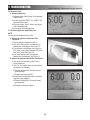
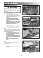
5.7 Ultrasound Applicator Identification Test
NOTE:
Use any Ultrasound Applicator for this test.
A. Ultrasound Applicator Identification Test
Procedures
1. Without Applicator installed, turn unit on.
2. Look at the display center. The Applicator not
detected icon should appear. See Figure 5.3.
3. Plug Applicator into Applicator port on the front
R.H. corner of the system. Applicator LED should
flash five (5) times. See Figure 5.4.
4. Look at the display center. The Applicator
detected icon should appear. See Figure 5.5.
B. Ultrasound Applicator Identification Test Results
1. Unit operates as described in steps 2 and 4.
a) Unit passed test.
2. “NO CAL” icon displays center of system display.
a) Applicator not calibrated.
b) Possible bad Applicator. Re-test with known
good Applicator.
c) Possible bad Ultrasound PCB.
3. Not detected icon displayed after ten seconds of
Applicator being plugged in.
a) Possible bad applicator. Re-test with known
good Applicator.
b) Possible bad Ultrasound Board.
FIGURE 5.3
FIGURE 5.4
FIGURE 5.5
12
5- TROUBLESHOOTING
Intelect®/Genisys® Ultrasound Therapy Systems
5.8 Ultrasound Applicator Output Test
Perform this test using all available Applicators for the unit
being tested.
A. Ultrasound Applicator Output Test Procedures
1.Set up Ohmic Instruments UPM DT 10 or UPM DT
100 Ultrasound Power Meter per Operator’s
Instructions and fill test reservoir with Degassed
Water.
!
WARNING
USE ONLY DEGASSED WATER IN POWER METER FOR
TESTING ULTRASOUND APPLICATORS. USE OF OTHER
TYPES OF WATER WILL CAUSE FALSE TEST RESULTS.
SEE PAGE 10 FOR DEGASSED WATER RECIPES.
DO NOT AERATE WATER WHEN FILLING POWER METER.
2.Place an Applicator into the Power Meter retainer.
As per Ohmic Manual, make certain the Applicator’s
aluminum face is submerged in the degassed water
and centered directly over the S.S. cone.
3. “Zero” the Power Meter.
4. Turn the Ultrasound Therapy System on.
5. Press the
button until “Continuous” is
displayed in the Duty Cycle area of the display.
6. Press the
button until “Watts” appears in the
intensity area of the display.
7. Increase Intensity for the applicator being tested
according to Figure 5.6
8. Press “Start”.
9. Compare Power Meter readings, displayed on
power meter for all the settings for each respective
applicator being tested to the values in Figure 5.6.
10. Press the
button until “3.3 MHz” is diplayed in
the Frequency area of the display. Repeat test and
compare readings to Figure 5.6.
B. Ultrasound Applicator Output Test Results
1. Output ranges fall within the specified ranges as
listed in Figure 5.6.
a) Unit passed test.
2. Readings fall outside specified ranges of Figure 5.6.
a)Possible bad Degassed Water in Power Meter.
b)Possible use of Power Meter other than Ohmic
Instruments UPM DT 10 or UPM DT 100
Ultrasound Power Meter.
c)Possible bad or out of calibration Applicator.
d)Possible bad Ultrasound Board.
APPLICATOR OUTPUT SPECIFICATIONS
APPLICATOR SIZE
1 cm2
2 cm2
5 cm2
10 cm2
POWER SETTING
(WATTS)
1
0.8 - 1.2
2
1.6 - 2.4
1
0.8 - 1.2
2
1.6 - 2.4
4
3.2 - 4.8
1
0.8 - 1.2
2
1.6 - 2.4
5
4.0 - 6.0
10
8.0 - 12.0
1
0.8 - 1.2
5
4.0 - 6.0
10
8.0 - 12.0
15
12.0 - 18.0
20
16.0 - 24.0
FIGURE 5.6
13
OUTPUT RANGE
5- TROUBLESHOOTING
Intelect®/Genisys® Ultrasound Therapy Systems
5.9 Ultrasound Duty Cycle Test
This test is performed using only the 5 cm2 Applicator.
A. Ultrasound Duty Cycle Test Procedures
1. Set up Ohmic Instruments UPM DT 10 or UPM DT
100 Ultrasound Power Meter per Operator’s
Instructions and fill test reservoir with Degassed
Water.
!
WARNING
USE ONLY DEGASSED WATER IN POWER METER FOR
TESTING ULTRASOUND APPLICATORS. USE OF OTHER
TYPES OF WATER WILL CAUSE FALSE TEST RESULTS. SEE
PAGE 10 FOR DEGASSED WATER RECIPES.
DO NOT AERATE WATER WHEN FILLING POWER METER.
2. Place an Applicator into the Power Meter retainer. As
per Ohmic Manual, make certain the Applicator’s
aluminum face is submerged in the degassed water
and centered directly over the S.S. cone.
3. “Zero” the Power Meter.
4. Turn the Ultrasound Therapy System on.
5. Press the
button until “Watts” appears in the
intensity area of the display.
6. Increase Intensity (
) to maximum.
7. Press “Start”.
8. Press the
button until “10%” is displayed in the
Duty Cycle area of the display.
9. Compare Power Meter readings to Figure 5.7 for
each of the following Duty Cycle settings listed in the
chart.
10. Press the
button until “3.3 MHz” is displayed in
the Frequency area of display. Repeat test and
compare readings to Figure 5.7.
B. Ultrasound Duty Cycle Test Results
1. Duty Cycles fall within the specified ranges as listed
in Figure 5.7.
a) Unit passed test
2. Readings fall outside specified ranges of Figure 5.7.
a) Possible bad Degassed Water in Power Meter.
b) Possible use of Power Meter other than Ohmic
Instruments UPM DT 10 or UPM DT 100
Ultrasound Power Meter.
c) Possible bad or out of calibration Applicator.
d) Check Ultrasound Board.
e) Check Control Board.
DUTY CYCLE SPECIFICATIONS
APPLICATOR SIZE
5 cm2
DUTY CYCLE
OUTPUT RANGE
10%
0.8 - 1.2
20%
1.6 - 2.4
50%
4.0 - 6.0
100% (Continuous)
8.0 - 12.0
FIGURE 5.7
14
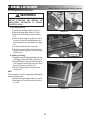
6- REMOVAL & REPLACEMENT
Intelect®/Genisys® Ultrasound Therapy Systems
6.1 General
!
REMOVE MAINS
POWER CORD
REMOVE
PLYNTH
WARNING
UNPLUG THE UNIT FROM THE POWER SOURCE
AND/OR REMOVE BATTERY BEFORE ATTEMPTING
ANY REMOVAL OR REPLACEMENT PROCEDURES
TO PREVENT ELECTRICAL SHOCK.
A. Tools & Equipment Required
1. #1 Phillips Screwdriver
2. Flat Blade Screwdriver
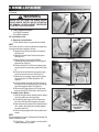
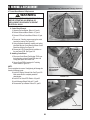
6.2. Top & Bottom of Unit
A. Removing Top from Bottom
1. Place unit face down on a grounded work surface.
NOTE:
Use a clean, soft cloth or cushion underneath the display lens
to prevent scratching or damage to the lens.
2. Remove the plynth from the bottom of the system.
See Figure 6.1.
3. Remove the Mains Power Cord from the system.
See Figure 6.1.
4. Remove Battery Cover with the Flat Blade
Screwdriver and remove Battery from the system if
equipped. See Figure 6.2.
5. Remove the Rear Fan Grill from the system to gain
access to the two rear mounting screws. See Figure
6.2.
6. Remove the two front feet from the system to gain
access to the two front screws. See Figure 6.3.
7. Remove the four mounting screws from the bottom
housing using the #1 Phillips Screwdriver. See
Figure 6.3.
8. Carefully separate the upper and lower housings of
the system. It may be necessary to pry the housings
apart at the Applicator Hook. See Figure 6.4.
9. Disconnect the Power Supply and Fan Harnesses
from the Control PCB of the system. See Figure 6.4.
B. Installing Top to Bottom
1. With top laying face down, carefully place the bottom
housing in position over the top housing.
2. Connect the Power Supply and Fan Harnesses to
the Control PCB onto their respective connectors.
3. Make certain the front insert and the Applicator Hook
are in position, then lightly press housings together
to properly seat them.
4. Secure housings together with the four phillips head
screws.
NOTE:
Do not overtighten the screws. Overtightening will damage the
threads of the brass inserts.
5. Follow Steps 1 - 7 in 6.2, A above in reverse order to
complete reassembly of system.
FIGURE 6.1
REMOVE
FAN GRILL
REMOVE BATTERY
COVER AND BATTERY
FIGURE 6.2
REMOVE
FOUR SCREWS
REMOVE
FRONT FEET
FIGURE 6.3
CAREFULLY PRY APART
HERE IF NECESSARY
APPLICATOR
HOOK
DISCONNECT POWER
SUPPLY AND FAN
HARNESSES
FIGURE 6.4
15
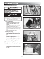
6- REMOVAL & REPLACEMENT
Intelect®/Genisys® Ultrasound Therapy Systems
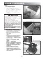
6.3 Fan Removal & Replacement
!
FAN
BAFFLE
REMOVE SCREWS
WARNING
UNPLUG THE UNIT FROM THE POWER SOURCE
BEFORE ATTEMPTING ANY REMOVAL OR
REPLACEMENT PROCEDURES TO PREVENT
ELECTRICAL SHOCK.
A. Fan Removal
1. Separate Top from Bottom. Refer to 6.2, part A.
2. With #1 Phillips screwdriver, remove the 2 screws
securing the Fan. See Figure 6.5.
3. Remove Fan from the unit.
4. Remove Fan Baffle from fan. See Figure 6.5.
B. Installing Fan
1. Route Fan Harness underneath fan as shown in
Figure 6.6.
2. Install Fan Baffle onto fan as shown in Figure 6.6.
3. Place new Fan, Part Number 27266, into system
base.
4. Make certain the Fan Baffle sits onto System
Housing Baffle Tabs as shown in Figure 6.7.
5. Secure fan to housing with the 2 mounting screws.
See Figure 6.8.
NOTE:
Do not overtighten the screws. Overtightening will damage the
threads of the brass inserts.
FIGURE 6.5
FAN
BAFFLE
ROUTE
HARNESS
AS SHOWN
FIGURE 6.6
BAFFLE
TABS
6. Reassemble the Top and Bottom Housing. Refer to
6.2, part B.
FIGURE 6.7
SECURELY TIGHTEN
MOUNTING SCREWS
FIGURE 6.8
16
6- REMOVAL & REPLACEMENT
Intelect®/Genisys® Ultrasound Therapy Systems
6.4 Power Supply Removal & Replacement
!
WARNING
UNPLUG THE UNIT FROM THE POWER SOURCE
BEFORE ATTEMPTING ANY REMOVAL OR
REPLACEMENT PROCEDURES TO PREVENT
ELECTRICAL SHOCK.
REMOVE SCREWS
DANGER
FIGURE 6.9
IF POWER SUPPLY HAS FAILED HI-POT TEST,
IT WILL RETAIN HIGH VOLTAGE IN THE
POWER SUPPLY CAPACITOR C4. DISCHARGE
CAPACITOR USING A MULTIMETER PRIOR ANY
SERVICE OF THE POWER SUPPLY
GREEN WITH
YELLOW STRIPE
A. Power Supply Removal
1. Separate Top from Bottom. Refer to 6.2, part A.
2. Discharge Power Supply Capacitor, C4, with
multimeter.
3. With #1 Phillips screwdriver, remove the 2 screws
securing the Power Supply. See Figure 6.9.
4. Lift Power Supply and disconnect the Power Supply
Harnesses from the Mains Disconnect. See Figure
6.10.
5. Remove Power Supply from system.
B. Installing Power Supply
1. Route Power Supply PCB Harness of new Power
Supply, Part Number 27265, as shown in Figure
6.11.
2. Connect Power Supply Mains Harness to Mains
Disconnect as shown in Figure 6.10
3. Make certain the Power Supply sits onto alignment
pins as shown in Figure 6.12.
5. Secure Power Supply to housing with the 2
mounting screws. See Figure 6.9.
NOTE:
Do not overtighten the screws. Overtightening will damage the
threads of the brass inserts.
BLUE
FIGURE 6.10
ROUTE HARNESS AS SHOWN
FIGURE 6.11
POWER SUPPLY
ALIGNMENT PINS
6. Reassemble the Top and Bottom Housing. Refer to
6.2, part B.
FIGURE 6.12
17
RED
6- REMOVAL & REPLACEMENT
Intelect®/Genisys® Ultrasound Therapy Systems
6.5 Ultrasound Board Removal & Replacement
!
SCREW
SCREW
WARNING
UNPLUG THE UNIT FROM THE POWER SOURCE
BEFORE ATTEMPTING ANY REMOVAL OR
REPLACEMENT PROCEDURES TO PREVENT
ELECTRICAL SHOCK.
A. Ultrasound Board Removal
1. Separate Top from Bottom. Refer to 6.2, part A.
2. With #1 Phillips screwdriver remove the 4 screws
securing the Ultrasound Board to the unit. See
Figure 6.13.
3. Carefully remove Ultrasound Board from the
Control Board/Ultrasound Board Connector. See
Figure 6.14.
4. Remove Control Board/Ultrasound Board Connector
from the Control Board. Be careful not to bend or
damage any of the pins. See Figure 6.14.
SCREW
SCREW
FIGURE 6.13
REMOVE CONNECTOR
FROM CONTROL BOARD
REMOVE US BOARD
FROM CONNECTOR
B. Installing Ultrasound Board
1. Install Control Board/Ultrasound Board Connector
into new Ultrasound Board, Part Number 27269.
NOTE:
Install the connector with the long pins inserted into Ultrasound
Board. Make certain connector is completely seated against
Ultrasound Board. See Figure 6.15.
2. Place new Ultrasound board as shown in Figure
6.16 over Control Board and align connector pins up
with Control Board Connector.
3. Carefully press the connector and board into place
until the connector is completely seated into Control
Board.
4. Secure Ultrasound Board with the 4 retaining
screws.
FIGURE 6.14
INSTALL CONNECTOR TO
US BOARD AS SHOWN
FIGURE 6.15
ALIGN CONNECTOR PINS
WITH CONTROL BOARD
CONNECTOR
NOTE:
Do not overtighten the screws. Overtightening will damage the
threads of the brass inserts.
5. Reassemble the Top and Bottom Housing. Refer to
6.2, part B.
FIGURE 6.16
18
6- REMOVAL & REPLACEMENT
Intelect®/Genisys® Ultrasound Therapy Systems
6.6 LCD Display Removal & Replacement
!
2 SCREWS
EACH END
WARNING
RELEASE RETAINING
BRACKET TABS
UNPLUG THE UNIT FROM THE POWER SOURCE
BEFORE ATTEMPTING ANY REMOVAL OR
REPLACEMENT PROCEDURES TO PREVENT
ELECTRICAL SHOCK.
A. LCD Display Removal
1. Separate Top from Bottom. Refer to 6.2, part A.
2. Remove Ultrasound Board. Refer to 6.7, part A.
3. Remove the 4 LCD retaining screws. See Figure
6.17.
4. With a flat blade screwdriver, gently push in and up
on each end of the LCD retaining brackets to free
the locking tabs from the Control Board. See Figure
6.17.
5. Set retaining brackets aside for reassembly.
6. Carefully remove the LCD from the Control Board
being careful not to damage the LCD connector pins.
See Figure 6.18.
B. Installing LCD Display
1. Reinstall the two LCD Retaining Brackets onto new
LCD Display, Part Number 27264. See Figure 6.19.
2. Place LCD Display over Control Board and align the
LCD Connector pins with the top row on the Control
Board LCD Connector. See Figure 6.18.
3. Secure LCD Display with the 4 retaining screws.
See Figure 6.17.
NOTE:
Do not overtighten the screws. Overtightening will damage the
threads of the brass inserts.
4. Reinstall the Ultrasound Board. Refer to 6.7, part B.
5. Reassemble the Top and Bottom Housing. Refer to
6.2, part B.
FIGURE 6.17
REMOVE LCD FROM
CONTROL BOARD
FIGURE 6.18
INSTALL RETAINING
BRACKETS TO LCD
FIGURE 6.19
19
6- REMOVAL & REPLACEMENT
Intelect®/Genisys® Ultrasound Therapy Systems
6.7 Control Board Removal & Replacement
!
RETAINING SCREWS
WARNING
UNPLUG THE UNIT FROM THE POWER SOURCE
BEFORE ATTEMPTING ANY REMOVAL OR
REPLACEMENT PROCEDURES TO PREVENT
ELECTRICAL SHOCK.
A. Control Board Removal
1. Separate Top from Bottom. Refer to 6.2, part A.
2. Remove Ultrasound Board. Refer to 6.7, part A.
3. Remove LCD from Control Board. Refer to 6.6, part
A.
4. Remove the 7 retaining screws securing the control
board to the housing. See Figure 6.20.
5. Using a flat blade screwdriver, carefully push locking
tabs while lifting the Control Board to release Control
Board from Housing. See Figure 6.21.
6. Remove the LCD Contrast knob for installation on
the new Control PCB. See Figure 6.22.
B. Installing Control Board
1. Place new Control Board, Part Number 27249, over
the locking tabs and push Control PCB down until
locking tabs capture the Control PCB.
2. Secure Control PCB to housing with 7 retaining
screws. Refer to Figure 6.20.
NOTE:
Do not overtighten the screws. Overtightening will damage the
threads of the brass inserts.
3. Install LCD Display Contrast Knob. See Figure 6.22.
Make certain Knob is completely seated on
potentiometer.
4. Install LCD to Control PCB. Refer to 6.6, part B.
5. Install Ultrasound Board. Refer to 6.7, part B.
6. Re-assemble Top to Bottom. Refer to 6.2, part B.
FIGURE 6.20
PUSH TABS IN AND
PULL UP ON BOARD
SIMUTANEOUSLY
FIGURE 6.21
CONTRAST KNOB
FIGURE 6.22
20
7- ULTRASOUND APPLICATOR CALIBRATION
Intelect®/Genisys® Ultrasound Therapy Systems
7.1 General
A. Tools and Equipment Required
1. Ultrasound Therapy System being serviced.
2. All Ultrasound Applicators for the unit being serviced.
3. Ohmic Instruments UPM DT 10 or UPM DT 100
Ultrasound Power Meter, set to “watts”.
4. Degassed Water. Refer to page 10 for Degassed
Water Recipes.
!
WARNING
USE ONLY DEGASSED WATER IN POWER METER FOR
CALIBRATING ULTRASOUND APPLICATORS.
USE OF OTHER TYPES OF WATER WILL CAUSE FALSE
READINGS AND BAD TEST RESULTS.
SEE PAGE 10 FOR DEGASSED WATER RECIPES.
USE OF OTHER BRANDS OR TYPES OF TOOLS,
EQUIPMENT, FIXTURES, MATERIALS AND SUPPLIES
OTHER THAN THOSE SPECIFICALLY LISTED IN “A. Tools
and Equipment Required” ABOVE WILL GIVE BAD TEST
AND CALIBRATION RESULTS.
IF PROPER EQUIPMENT IS NOT AVAILABLE OR CAN NOT
BE OBTAINED, SEND THE ULTRASOUND APPLICATORS
TO THE FACTORY FOR CALIBRATION.
FIGURE 7.1
B. Ultrasound Applicator Calibration Procedures
1. Perform the following on all Ultrasound Applicators
for the unit being serviced at least annually.
2. With the system on, press the Clinical Resources
button once. See
Figure 7.1.
3. Simultaneously press and hold the Treatment Time
and Intensity Down buttons for approximately 2
seconds. See Figure 7.2. The calibration procedures
screen should display.
4. Press the
icon once to highlight “Calibrate
Applicator”.
5. Press the
icon once to select.
6. Place the Ultrasound Applicator being calibrated into
the Ohmic Instruments UPM DT 10 or UPM DT 100
Ultrasound Power Meter and set meter to “watts”.
See Figure 7.3.
7. Follow the instructions on the LCD Display.
8. When calibration is complete, place another
applicator on the Ohmic Instruments UPM DT 10
or UPM DT 100 Ultrasound Power Meter and repeat
steps 1 through 6 above.
FIGURE 7.2
SET METER
TO WATTS
FIGURE 7.3
21
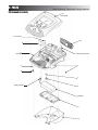
8- PARTS
Intelect®/Genisys® Ultrasound Therapy Systems
Ultrasound Assembly
1&2
(See Page 24)
Fan Connector
3&4
12
11
(See Pages26 - 27)
Power Supply Connector
5
5
10
5
Battery Connector
6
7 (Optional)
8
9
22
8- PARTS
Intelect®/Genisys® Ultrasound Therapy Systems
Ultrasound Assembly
ITEM
NUMBER
1
2
3
4
5
6
7
8
9
10
11
12
PART
NUMBER
27402
27247
27361
27363
27142
27365
27267
27410
27253
27363
27409
27373
DESCRIPTION
Top Assembly (Grey)- See page 24 for breakdown
Top Assembly (Blue)- See Page 24 for breakdown
Rear Vent (Grey)
Rear Vent (Blue)
M3 x 6mm S.S. Pan Head Screw
Right Foot
Battery Pack (Optional)
Battery Compartment Cover Assembly
Plynth
Left Foot
Bottom Assembly- See Pages 26-27 for breakdown
Baffle
23
QTY
REQ’D
1
1
1
1
4
1
1
1
1
1
1
1
8- PARTS
Intelect®/Genisys® Ultrasound Therapy Systems
Ultrasound Top Assembly
1 & 1A
2 & 2A
3 & 3A
4
(See Page 25)
5
6
7
5
ITEM
PART
NUMBER NUMBER
1
1A
2
2A
3
3A
4
5
6
7
27552
27553
27370
27262
27368
27561
27249
27142
27588
27269
DESCRIPTION
Top Moulding Assembly (Grey)
Top Moulding Assembly (Blue)
Power Button (Grey)
Power Button (Blue)
Keymat (Grey)
Keymat (Blue)
Control PCB Assembly- See Page 25
M3 x 6mm S.S. Pan Head Screw
PCB Connector- Ultrasound PCB to Control PCB
Ultrasound PCB Assembly
24
QTY
REQ’D
1
1
1
1
1
1
1
15
1
1
8- PARTS
Intelect®/Genisys® Ultrasound Therapy Systems
Ultrasound Control PCB Assembly
1
2
3
4
4
ITEM
NUMBER
1
2
3
4
PART
NUMBER
27268
27012
27264
27261
DESCRIPTION
Control PCB
Contrast Knob
Transportables LCD
LCD Spacer
25
QTY
REQ’D
1
1
1
2
8- PARTS
Intelect®/Genisys® Ultrasound Therapy Systems
Ultrasound Bottom Assembly
1
2
3
4
5
4
9
6
8
7
26
8- PARTS
Intelect®/Genisys® Ultrasound Therapy Systems
Ultrasound Bottom Assembly
ITEM
NUMBER
1
2
3
4
5
6
7
8
9
PART
NUMBER
27136
27266
27367
27142
27265
27277
27256
27252
27259
DESCRIPTION
M4 x 35mm S.S. Pan Head Screw
Fan
Fan Seal
M3 x 6mm S.S. Pan Head Screw
Power Supply
Universal Snap-In Inlet
Applicator Hang-Up
Base
Ultrasound Connector Infill
27
QTY
REQ’D
2
1
1
2
1
1
1
1
1
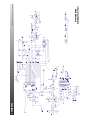
10nF
C7
10nF
C8
DGND_APPL
NOT Case
Connected
VCC_APPL
28
C9
US+
1
T1
EFD15
8
2
PIN1
LED1
10nF
C1
2
4
6
8
10
1
3
5
7
9
JP1
pplicator
10- Ap
plicator Body
9- I C2 CLOCK
7- I C2 DATA
6,8- US-
5- +5V
US-
330pF/200V
6
5
4
7 1
3
2
1
3
6
1
1
BAS16_NL
D1
1
10nF
C2
8
1- N/C
1K
R1
3- MCLR
10K
2,4- US+
F1
1
2
R6
1
2
MCLR
1
2
1
2
SDA_APPL
2
K1
220
R5
G6K-2
2F-YY5VDC
2
0.1uF
C3
1K
R2
1
2
SCL_APPL
3
2
4
7
5
C6
1
1.0uF/16V
1
1
1
1
PAD1
50PAD
1
1
1
PAD2
50PAD
4
3
2
1
1
PIN2
Case Connected
PAD4
50PAD
100PAD
PAD3
50PAD
1
GP3/MCLR/VPP
10nF
C4
2
Transducer
10K
R7
GP4/AN3/T1G/OSC2/CLKOUT
GP5/T1CKI/OSC1/CLKIN
VDD
1
2
9- SCHEMATICS
1
1
10K
R3
PIC12F675-II /SN
U1
2
1
1
1
PIN3
100PAD
1
MMBT3904
Q4
GP2/AN2/T0CKI/INT/COUT
GP1/AN1/CIN-//VREF/ICSPCLK
GP0/AN0/CIN+/ICSPDAT
3
2
VSS
8
5
6
7
C5
0.1uF
RT1
100K
Next to Pin 1
Thermal connect
5 cm2 Ultrasound Applicator
Schematic
220uH
L2
42.2K 1%
R4
Intelect®/Genisys® Ultrasound Therapy Systems
1
2
1
1 2
2
9- SCHEMATICS
29
Control Board- 27268
Schematic 1 of 2
Intelect®/Genisys® Ultrasound Therapy Systems
9- SCHEMATICS
30
Control Board- 27268
Schematic 2 of 2
Intelect®/Genisys® Ultrasound Therapy Systems
I2C_DATA
I2C_CLOCK
CLK_REF
DUTY_CYCLE
GND
3
2
1
TPS2819DBV
IN
GND
VDD
U2
VCC
2.2K
R25
0.1uF
C25
GND
OUT
VCC
4
5
1
1
GND
2.2
R9
FB2
2.2K
R26
HZ1206
VCC
GND
2
C15
4
8
6
5
7
3
2
1
0.1uF
1
2
GND
1.0M
R10
VSS
VDD
XOUT
XIN
ADDR1
ADDR0
SDA
SCL
2
GND
1
U5
31
4.7uF/25V
C26
EXTLF
REF
FBK
CLKP
CLKN
VSS
VDD
LOCK/IPRG
FS6131-0
01
IRLR110
Q4
4.7uF/25V
C16
4
3
HZ1206
1
2
1
2
1
2
0.1uF
C27
GND
11
14
9
10
12
13
15
16
12
GND
GND
74HC27D
U1A
47
R2
47
R1
1
2
13
1.0M
R11
IRLR110
Q7
100pF/100V
C2
1
1
620
R27
1
2
2.2
R12
33uF/50V
C4
4.7uF/25V
C3
+40VADJ
47pF
C17
GND
2
620
R28
2
0.1uF
C18
GND
0.1uF/50V
C6
0.1uF/50V
C5
GND
1
GND
GND
4
5
9
11
OUT
5
4
GND
1
VCC
8
GND
2
8
7
6
5
74HC27D
U1C
0.1uF
IN
GND
VDD
C29
74HC27D
U1B
TPS2819DBV
U3
ENG00787
3
VCC
47pF
C28
10
1
2
3
4
T1
6
3
2
1
TESTPOINT
TP14
GND
HZ1206
FB10
VCC
BAS16
D3
VIN
3
NL
C98
22_NL
R160
Q8
GND
12
1
9
4
1
2N7002
TX2-2
24V
K1
10K
R13
8
1_3MHZ
10
5
3
2
2
9
12
8
4
TX2-2
24V
K2
GND
1
2
10
5
3
C11
L2
1
2
4.7uF/25V
1
100uH
C12
0.56
R5
0.1uF
GND
0
R112
2
IRF
US_GND
2
5
8
2
5
8
L3
TESTPOINT
TP1
US Ground
DRAIN
1
3
4
6
FB1
HZ1206
1
2
2.8uH/2A
1
1000pF/250V
C10
C9
1
3300pF/250V
1
L1
11.5uH/2A
VCC
S1
S1
1
2
SOUNDHEAD CONNECTOR
7
7
S2
S2
6
S3
S3
1
2
2
1
2
1
1
2
1
1
2
2
1
1
2
2
100pF/100V
4
3
1
2
1
2
1
2
1
2
1
2
FB9
1
2
1
2
3
2
1
1 2
2
VCC
1
2
1
2
1
2
1
C1
14
7
1
2
1
3
4
KMDG-8
8S-BBS
J1
GND
1
1.00K
R18
14.0K
R17
0.1uF
C19
100uH_NL
L4
US_GND
GND
2
C20
2
0.1uF
C21
2
3
0.1uF
C22
GND
1
1
-
+
1
R22
1.00K
R21
-5
5V
LMH6642MA
U4
6
1.5K_NL
VCC
300K_NL
R20
1
1.5K_NL
R19
2
2
GND
0.1uF_NL
C23
10nF
C13
100
R7
0_NL
R23
GND
0
R151
0
R152
HEAD_DETECT
10nF
C14
100
R8
VRF
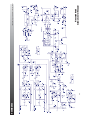
Ultrasound Board
Schematic 1 of 3 (AMP)
GND
GND
2
0.1uF_NL
0
R157
0
R156
Intelect®/Genisys® Ultrasound Therapy Systems
1
2
1
21
2
1
21
2
9- SCHEMATICS
1
1
2 2
12
1
1
2
2
12
1
7
4
2
1
HEAD_CLOCK
HEAD_DATA
9- SCHEMATICS
32
Ultrasound Board
Schematic 2 of 3 (Ports)
Intelect®/Genisys® Ultrasound Therapy Systems
9- SCHEMATICS
33
Ultrasound Board
Schematic 3 of 3 (V Supply)
Intelect®/Genisys® Ultrasound Therapy Systems
10- WARRANTY
Intelect®/Genisys® Ultrasound Therapy Systems
Chattanooga Group ("Company") warrants that the Ultrasound Therapy System("Product") is free of defects in material and
workmanship. This warranty shall remain in effect for two years (24 months) from the date of original consumer purchase. If this
Product fails to function during the two years warranty period due to a defect in material or workmanship, Company or the selling
dealer will repair or replace this Product without charge within a period of thirty (30) days from the date on which the Product is
returned to the Company or the dealer.
All repairs to the Product must be performed by a service center certified by the Company. Any modifications or repairs performed
by unauthorized centers or groups will void this warranty.
The warranty period for applicators is one year (12 months).
This Warranty Does Not Cover:
Replacement parts or labor furnished by anyone other than the Company, the selling dealer or a certified Company service
technician.
Defects or damage caused by labor furnished by someone other than Company, the selling dealer or a certified Company service
technician.
Any malfunction or failure in the Product caused by product misuse, including, but not limited to, the failure to provide reasonable
and necessary maintenance or any use that is inconsistent with the Product User's Manual.
COMPANY SHALL NOT BE LIABLE IN ANY EVENT FOR INCIDENTAL OR CONSEQUENTIAL DAMAGES.
Some states do not allow the exclusion or limitation of incidental or consequential damages, so the above limitation or exclusion may
not apply to you.
To Obtain Service From Company or the selling dealer under this warranty:
1. A written claim must be made within the warranty period to the Company or the selling dealer. Written claims made to the
Company should be
sent to:
4717 Adams Road
Hixson, TN 37343 USA
Telephone: +1 423 870-7200
FAX: +1 423 870-2046
and
2. The Product must be returned to the Company or the selling dealer by the owner.
This warranty gives you specific legal rights and you may also have other rights which vary from state to state or location to
location.
The Company does not authorize any person or representative to create for it any other obligation or liability in connection with the
sale of the Product. Any representation or agreement not contained in the warranty shall be void and of no effect.
THE FOREGOING WARRANTY IS IN LIEU OF ALL OTHER WARRANTIES, EXPRESSED OR IMPLIED,
INCLUDING ANY WARRANTY OR MERCHANTABILITY OR FITNESS FOR A PARTICULAR PURPOSE.
34
More Trusted Products from Chattanooga Group
®
Adapta
Massage Tables & Chairs
™
A.E.R. Boot
Auto Edema Reduction Boot
™
A.E.R. Compression System
Hot and Cold Compression Therapy
boo-boo pac™
Child Size Bear-Shaped Cold Pack
®
Cambion
Shock Dampening Foot Care Products
®
Can-do
Exercise Bands, Tubes and Balls
Carpal-Trac™
Carpal Traction Accessory
Cervical Traction System
Clinical Cervical Traction
®
ColPaC
Chilling Units and Reusable Cold Therapy Products
Conductor Gel™
Highly Conductive Ultrasound Gel
Contracture Products
Contracture Management Orthotic Products
DURA-STICK® Electrodes
Self-Adhesive Electrodes
EMG Retrainer® and EMG Retrainer® IR
Dual Channel Surface EMG
Ergostyle®
Chiropractic Tables
Flexi-PAC® I and II
Reusable Hot
and Cold Compresses
®
Fluido DHT
Dry Heat Whirlpool Therapy Units
Gel Medex™
Gel Mattress Overlay
®
Hydrocollator
Heating Units and HotPacs™
Intelect ®
Ultrasound and Electrotherapy Products
Magneciser™
Exercise Equipment
Measurement Instruments
Dynamometers, Goniometers, ect.
Myossage®
Massage Lotion
Nylatex®
Elastic Wraps
OptiFlex®
Continuous Passive Motion
Opti-Ice™
Cold Therapy System
Para-Care®
Paraffin Wax Unit
Pillow Perfect™
Cervical Pillow Line
Pivotal Therapy System™
Orthotics for the Spine
®
PresSsion
Intermittent Compression
™
Pron Pillo
Positioning Pillow
SensaFlex™
Hot/Cold Pack
SPORT-PAC™
Soccer Ball Shaped Cold Pack
Therma-Wrap™
Hot and Cold Compression
Triton®
Treatment and Traction Equipment
Tru-Trac®
Traction Equipment
Wellness 1st™
Back Support
ISO 13485 CERTIFIED
4717 Adams Road
P.O. Box 489
Hixson, TN 37343 U.S.A.
+1-423-870-7200 OUTSIDE U.S.A
+1 423-870-2046 OUTSIDE U.S.A. FAX
www.chattgroup.com
0413
27670A
© 2004 Encore Medical, L.P.