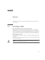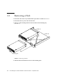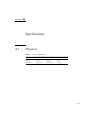
1
Sun™ StorEdge™ FC-100 Hub
Installation and Service
Manual
Formerly the Sun™ Enterprise Network Array™
Sun Microsystems, Inc.
901 San Antonio Road
Palo Alto, CA 94303-4900 USA
650 960-1300
Fax 650 969-9131
Part No. 805-0315-12
September 1998, Revision A
Send comments about this document to: [email protected]
Copyright 1998 Sun Microsystems, Inc. 901 San Antonio Road • Palo Alto, CA 94303 USA. All rights reserved.
This product or document is protected by copyright and distributed under licenses restricting its use, copying, distribution, and decompilation.
No part of this product or document may be reproduced in any form by any means without prior written authorization of Sun and its licensors,
if any. Third-party software, including font technology, is copyrighted and licensed from Sun suppliers.
Parts of the product may be derived from Berkeley BSD systems, licensed from the University of California. UNIX is a registered trademark in
the U.S. and other countries, exclusively licensed through X/Open Company, Ltd.
Sun, Sun Microsystems, the Sun logo, AnswerBook, Sun StorEdge, Sun Enterprise Network Array and Solaris are trademarks, registered
trademarks, or service marks of Sun Microsystems, Inc. in the U.S. and other countries. All SPARC trademarks are used under license and are
trademarks or registered trademarks of SPARC International, Inc. in the U.S. and other countries. Products bearing SPARC trademarks are
based upon an architecture developed by Sun Microsystems, Inc.
The OPEN LOOK and Sun™ Graphical User Interface was developed by Sun Microsystems, Inc. for its users and licensees. Sun acknowledges
the pioneering efforts of Xerox in researching and developing the concept of visual or graphical user interfaces for the computer industry. Sun
holds a non-exclusive license from Xerox to the Xerox Graphical User Interface, which license also covers Sun’s licensees who implement OPEN
LOOK GUIs and otherwise comply with Sun’s written license agreements.
RESTRICTED RIGHTS: Use, duplication, or disclosure by the U.S. Government is subject to restrictions of FAR 52.227-14(g)(2)(6/87) and
FAR 52.227-19(6/87), or DFAR 252.227-7015(b)(6/95) and DFAR 227.7202-3(a).
DOCUMENTATION IS PROVIDED “AS IS” AND ALL EXPRESS OR IMPLIED CONDITIONS, REPRESENTATIONS AND WARRANTIES,
INCLUDING ANY IMPLIED WARRANTY OF MERCHANTABILITY, FITNESS FOR A PARTICULAR PURPOSE OR NONINFRINGEMENT, ARE DISCLAIMED, EXCEPT TO THE EXTENT THAT SUCH DISCLAIMERS ARE HELD TO BE LEGALLY INVALID.
Copyright 1998 Sun Microsystems, Inc., 901 San Antonio Road • Palo Alto, CA 94303 Etatis-Unis. Tous droits réservés.
Ce produit ou document est protégé par un copyright et distribué avec des licences qui en restreignent l’utilisation, la copie, la distribution, et la
décompilation. Aucune partie de ce produit ou document ne peut être reproduite sous aucune forme, par quelque moyen que ce soit, sans
l’autorisation préalable et écrite de Sun et de ses bailleurs de licence, s’il y en a. Le logiciel détenu par des tiers, et qui comprend la technologie
relative aux polices de caractères, est protégé par un copyright et licencié par des fournisseurs de Sun.
Des parties de ce produit pourront être dérivées des systèmes Berkeley BSD licenciés par l’Université de Californie. UNIX est une marque
déposée aux Etats-Unis et dans d’autres pays et licenciée exclusivement par X/Open Company, Ltd.
Sun, Sun Microsystems, le logo Sun, AnswerBook, Sun StorEdge, Sun Enterprise Network Array et Solaris sont des marques de fabrique ou des
marques déposées, ou marques de service, de Sun Microsystems, Inc. aux Etats-Unis et dans d’autres pays. Toutes les marques SPARC sont
utilisées sous licence et sont des marques de fabrique ou des marques déposées de SPARC International, Inc. aux Etats-Unis et dans d’autres
pays. Les produits portant les marques SPARC sont basés sur une architecture développée par Sun Microsystems, Inc.
L’interface d’utilisation graphique OPEN LOOK et Sun™ a été développée par Sun Microsystems, Inc. pour ses utilisateurs et licenciés. Sun
reconnaît les efforts de pionniers de Xerox pour la recherche et le développement du concept des interfaces d’utilisation visuelle ou graphique
pour l’industrie de l’informatique. Sun détient une licence non exclusive de Xerox sur l’interface d’utilisation graphique Xerox, cette licence
couvrant également les licenciés de Sun qui mettent en place l’interface d’utilisation graphique OPEN LOOK et qui en outre se conforment aux
licences écrites de Sun.
CETTE PUBLICATION EST FOURNIE "EN L’ETAT" ET AUCUNE GARANTIE, EXPRESSE OU IMPLICITE, N’EST ACCORDEE, Y
COMPRIS DES GARANTIES CONCERNANT LA VALEUR MARCHANDE, L’APTITUDE DE LA PUBLICATION A REPONDRE A UNE
UTILISATION PARTICULIERE, OU LE FAIT QU’ELLE NE SOIT PAS CONTREFAISANTE DE PRODUIT DE TIERS. CE DENI DE
GARANTIE NE S’APPLIQUERAIT PAS, DANS LA MESURE OU IL SERAIT TENU JURIDIQUEMENT NUL ET NON AVENU.
Regulatory Compliance Statements
Your Sun product is marked to indicate its compliance class:
•
•
•
Federal Communications Commission (FCC) — USA
Department of Communications (DOC) — Canada
Voluntary Control Council for Interference (VCCI) — Japan
Please read the appropriate section that corresponds to the marking on your Sun product before attempting to install the product.
FCC Class A Notice
This device complies with Part 15 of the FCC Rules. Operation is subject to the following two conditions:
1. This device may not cause harmful interference.
2. This device must accept any interference received, including interference that may cause undesired operation.
Note: This equipment has been tested and found to comply with the limits for a Class A digital device, pursuant to Part 15 of the FCC
Rules. These limits are designed to provide reasonable protection against harmful interference when the equipment is operated in a
commercial environment. This equipment generates, uses and can radiate radio frequency energy and, if not installed and used in
accordance with the instruction manual, may cause harmful interference to radio communications. Operation of this equipment in a
residential area is likely to cause harmful interference in which case the user will be required to correct the interference at his own
expense.
Shielded Cables: Connections between the workstation and peripherals must be made using shielded cables in order to maintain
compliance with FCC radio frequency emission limits. Networking connections can be made using unshielded twisted-pair (UTP)
cables.
Modifications: Any modifications made to this device that are not approved by Sun Microsystems, Inc. may void the authority
granted to the user by the FCC to operate this equipment.
FCC Class B Notice
This device complies with Part 15 of the FCC Rules. Operation is subject to the following two conditions:
1. This device may not cause harmful interference.
2. This device must accept any interference received, including interference that may cause undesired operation.
Note: This equipment has been tested and found to comply with the limits for a Class B digital device, pursuant to Part 15 of the FCC
Rules. These limits are designed to provide reasonable protection against harmful interference in a residential installation. This
equipment generates, uses and can radiate radio frequency energy and, if not installed and used in accordance with the instructions,
may cause harmful interference to radio communications. However, there is no guarantee that interference will not occur in a
particular installation. If this equipment does cause harmful interference to radio or television reception, which can be determined by
turning the equipment off and on, the user is encouraged to try to correct the interference by one or more of the following measures:
•
•
•
•
Reorient or relocate the receiving antenna.
Increase the separation between the equipment and receiver.
Connect the equipment into an outlet on a circuit different from that to which the receiver is connected.
Consult the dealer or an experienced radio/television technician for help.
Shielded Cables: Connections between the workstation and peripherals must be made using shielded cables in order to maintain
compliance with FCC radio frequency emission limits. Networking connections can be made using unshielded twisted pair (UTP)
cables.
Modifications: Any modifications made to this device that are not approved by Sun Microsystems, Inc. may void the authority
granted to the user by the FCC to operate this equipment.
Regulatory Compliance Statements
iii
DOC Class A Notice - Avis DOC, Classe A
This Class A digital apparatus meets all requirements of the Canadian Interference-Causing Equipment Regulations.
Cet appareil numérique de la classe A respecte toutes les exigences du Règlement sur le matériel brouilleur du Canada.
DOC Class B Notice - Avis DOC, Classe B
This Class B digital apparatus meets all requirements of the Canadian Interference-Causing Equipment Regulations.
Cet appareil numérique de la classe B respecte toutes les exigences du Règlement sur le matériel brouilleur du Canada.
iv
Sun StorEdge FC-100 Hub Installation and Service Manual • September 1998
Safety Agency Compliance Statements
Read this section before beginning any procedure. The
following text provides safety precautions to follow when
installing a Sun Microsystems product.
Safety Precautions
For your protection, observe the following safety precautions
when setting up your equipment:
• Follow all cautions and instructions marked on the
equipment.
• Ensure that the voltage and frequency of your power
source match the voltage and frequency inscribed on the
equipment’s electrical rating label.
• Never push objects of any kind through openings in the
equipment. Dangerous voltages may be present.
Conductive foreign objects could produce a short circuit
that could cause fire, electric shock, or damage to your
equipment.
Symbols
Placement of a Sun Product
!
Caution – Do not block or cover the openings of your
Sun product. Never place a Sun product near a
radiator or heat register. Failure to follow these
guidelines can cause overheating and affect the
reliability of your Sun product.
SELV Compliance
Safety status of I/O connections comply to SELV
requirements.
Power Cord Connection
Caution – Sun products are designed to work with
single-phase power systems having a grounded
neutral conductor. To reduce the risk of electric
shock, do not plug Sun products into any other type
of power system. Contact your facilities manager or a
qualified electrician if you are not sure what type of
power is supplied to your building.
The following symbols may appear in this book:
!
Caution – There is risk of personal injury and
equipment damage. Follow the instructions.
Caution – Hot surface. Avoid contact. Surfaces are
hot and may cause personal injury if touched.
Caution – Hazardous voltages are present. To reduce
the risk of electric shock and danger to personal
health, follow the instructions.
On – Applies AC power to the system.
Depending on the type of power switch your device has, one
of the following symbols may be used:
Off – Removes AC power from the system.
Standby – The On/Standby switch is in the standby
position.
Caution – Not all power cords have the same current
ratings. Household extension cords do not have
overload protection and are not meant for use with
computer systems. Do not use household extension
cords with your Sun product.
Caution – Your Sun product is shipped with a
grounding type (three-wire) power cord. To reduce
the risk of electric shock, always plug the cord into a
grounded power outlet.
The following caution applies only to devices with a
Standby power switch:
Caution – The power switch of this product functions
as a standby type device only. The power cord serves
as the primary disconnect device for the system. Be
sure to plug the power cord into a grounded power
outlet that is nearby the system and is readily
accessible. Do not connect the power cord when the
power supply has been removed from the system
chassis.
Modifications to Equipment
System Unit Cover
Do not make mechanical or electrical modifications to the
equipment. Sun Microsystems is not responsible for
regulatory compliance of a modified Sun product.
You must remove the cover of your Sun computer system
unit in order to add cards, memory, or internal storage
devices. Be sure to replace the top cover before powering up
your computer system.
Safety Agency Compliance Statements
v
!
Caution – Do not operate Sun products without the
top cover in place. Failure to take this precaution
may result in personal injury and system damage.
Achtung – Gefährliche Spannungen. Anweisungen
befolgen, um Stromschläge und Verletzungen zu
vermeiden.
Laser Compliance Notice
Sun products that use laser technology comply with
Class 1 laser requirements.
Ein – Setzt das System unter Wechselstrom.
Je nach Netzschaltertyp an Ihrem Gerät kann eines der
folgenden Symbole benutzt werden:
Class 1 Laser Product
Luokan 1 Laserlaite
Klasse 1 Laser Apparat
Laser Klasse 1
Einhaltung sicherheitsbehördlicher
Vorschriften
Auf dieser Seite werden Sicherheitsrichtlinien beschrieben,
die bei der Installation von Sun-Produkten zu beachten sind.
Sicherheitsvorkehrungen
Treffen Sie zu Ihrem eigenen Schutz die folgenden
Sicherheitsvorkehrungen, wenn Sie Ihr Gerät installieren:
• Beachten Sie alle auf den Geräten angebrachten
Warnhinweise und Anweisungen.
• Vergewissern Sie sich, daß Spannung und Frequenz Ihrer
Stromquelle mit der Spannung und Frequenz
übereinstimmen, die auf dem Etikett mit den elektrischen
Nennwerten des Geräts angegeben sind.
• Stecken Sie auf keinen Fall irgendwelche Gegenstände in
Öffnungen in den Geräten. Leitfähige Gegenstände
könnten aufgrund der möglicherweise vorliegenden
gefährlichen Spannungen einen Kurzschluß verursachen,
der einen Brand, Stromschlag oder Geräteschaden
herbeiführen kann.
Symbole
Die Symbole in diesem Handbuch haben folgende
Bedeutung:
!
Achtung – Gefahr von Verletzung und
Geräteschaden. Befolgen Sie die Anweisungen.
Aus – Unterbricht die Wechselstromzufuhr zum
Gerät.
Wartezustand (Stand-by-Position) - Der Ein-/
Wartezustand-Schalter steht auf Wartezustand.
Änderungen an Sun-Geräten.
Nehmen Sie keine mechanischen oder elektrischen
Änderungen an den Geräten vor. Sun Microsystems,
übernimmt bei einem Sun-Produkt, das geändert wurde,
keine Verantwortung für die Einhaltung behördlicher
Vorschriften
Aufstellung von Sun-Geräten
!
Achtung – Um den zuverlässigen Betrieb Ihres SunGeräts zu gewährleisten und es vor Überhitzung zu
schützen, dürfen die Öffnungen im Gerät nicht
blockiert oder verdeckt werden. Sun-Produkte sollten
niemals in der Nähe von Heizkörpern oder
Heizluftklappen aufgestellt werden.
Einhaltung der SELV-Richtlinien
Die Sicherung der I/O-Verbindungen entspricht den
Anforderungen der SELV-Spezifikation.
Anschluß des Netzkabels
Achtung – Sun-Produkte sind für den Betrieb an
Einphasen-Stromnetzen mit geerdetem Nulleiter
vorgesehen. Um die Stromschlaggefahr zu
reduzieren, schließen Sie Sun-Produkte nicht an
andere Stromquellen an. Ihr Betriebsleiter oder ein
qualifizierter Elektriker kann Ihnen die Daten zur
Stromversorgung in Ihrem Gebäude geben.
Achtung – Hohe Temperatur. Nicht berühren, da
Verletzungsgefahr durch heiße Oberfläche besteht.
vi
Sun StorEdge FC-100 Hub Installation and Service Manual • September 1998
Achtung – Nicht alle Netzkabel haben die gleichen
Nennwerte. Herkömmliche, im Haushalt verwendete
Verlängerungskabel besitzen keinen
Überlastungsschutz und sind daher für
Computersysteme nicht geeignet.
Achtung – Ihr Sun-Gerät wird mit einem dreiadrigen
Netzkabel für geerdete Netzsteckdosen geliefert. Um
die Gefahr eines Stromschlags zu reduzieren,
schließen Sie das Kabel nur an eine fachgerecht
verlegte, geerdete Steckdose an.
Die folgende Warnung gilt nur für Geräte mit WartezustandNetzschalter:
Achtung – Der Ein/Aus-Schalter dieses Geräts
schaltet nur auf Wartezustand (Stand-By-Modus).
Um die Stromzufuhr zum Gerät vollständig zu
unterbrechen, müssen Sie das Netzkabel von der
Steckdose abziehen. Schließen Sie den Stecker des
Netzkabels an eine in der Nähe befindliche, frei
zugängliche, geerdete Netzsteckdose an. Schließen
Sie das Netzkabel nicht an, wenn das Netzteil aus der
Systemeinheit entfernt wurde.
Gehäuseabdeckung
Sie müssen die obere Abdeckung Ihres Sun-Systems
entfernen, um interne Komponenten wie Karten,
Speicherchips oder Massenspeicher hinzuzufügen. Bringen
Sie die obere Gehäuseabdeckung wieder an, bevor Sie Ihr
System einschalten.
!
Achtung – Bei Betrieb des Systems ohne obere
Abdeckung besteht die Gefahr von Stromschlag und
Systemschäden.
Einhaltung der Richtlinien für Laser
Sun-Produkte, die mit Laser-Technologie arbeiten,
entsprechen den Anforderungen der Laser Klasse 1.
Class 1 Laser Product
Luokan 1 Laserlaite
Klasse 1 Laser Apparat
Laser Klasse 1
Conformité aux normes de sécurité
Ce texte traite des mesures de sécurité qu’il convient de
prendre pour l’installation d’un produit Sun Microsystems.
Mesures de sécurité
Pour votre protection, veuillez prendre les précautions
suivantes pendant l’installation du matériel :
• Suivre tous les avertissements et toutes les instructions
inscrites sur le matériel.
• Vérifier que la tension et la fréquence de la source
d’alimentation électrique correspondent à la tension et à la
fréquence indiquées sur l’étiquette de classification de
l’appareil.
• Ne jamais introduire d’objets quels qu’ils soient dans une
des ouvertures de l’appareil. Vous pourriez vous trouver
en présence de hautes tensions dangereuses. Tout objet
conducteur introduit de la sorte pourrait produire un
court-circuit qui entraînerait des flammes, des risques
d’électrocution ou des dégâts matériels.
Symboles
Vous trouverez ci-dessous la signification des différents
symboles utilisés :
!
Attention : risques de blessures corporelles et de
dégâts matériels. Veuillez suivre les instructions.
Attention : surface à température élevée. Evitez le
contact. La température des surfaces est élevée et leur
contact peut provoquer des blessures corporelles.
Attention : présence de tensions dangereuses. Pour
éviter les risques d’électrocution et de danger pour la
santé physique, veuillez suivre les instructions.
MARCHE – Votre système est sous tension (courant
alternatif).
Un des symboles suivants sera peut-être utilisé en fonction
du type d'interrupteur de votre système:
ARRET – Votre système est hors tension (courant
alternatif).
VEILLEUSE – L'interrupteur Marche/Veilleuse est
en position « Veilleuse ».
Safety Agency Compliance Statements
vii
Modification du matériel
Ne pas apporter de modification mécanique ou électrique au
matériel. Sun Microsystems n’est pas responsable de la
conformité réglementaire d’un produit Sun qui a été modifié.
L'avertissement suivant s'applique uniquement aux systèmes
équipés d'un interrupteur VEILLEUSE:
Attention : le commutateur d’alimentation de ce
produit fonctionne comme un dispositif de mise en
veille uniquement. C’est la prise d’alimentation qui
sert à mettre le produit hors tension. Veillez donc à
installer le produit à proximité d’une prise murale
facilement accessible. Ne connectez pas la prise
d’alimentation lorsque le châssis du système n’est
plus alimenté.
Positionnement d’un produit Sun
!
Attention : pour assurer le bon fonctionnement de
votre produit Sun et pour l’empêcher de surchauffer,
il convient de ne pas obstruer ni recouvrir les
ouvertures prévues dans l’appareil. Un produit Sun
ne doit jamais être placé à proximité d’un radiateur
ou d’une source de chaleur.
Conformité SELV
Sécurité : les raccordements E/S sont conformes aux normes
SELV.
Connexion du cordon d’alimentation
Attention : les produits Sun sont conçus pour
fonctionner avec des alimentations monophasées
munies d’un conducteur neutre mis à la terre. Pour
écarter les risques d’électrocution, ne pas brancher de
produit Sun dans un autre type d’alimentation
secteur. En cas de doute quant au type d’alimentation
électrique du local, veuillez vous adresser au
directeur de l’exploitation ou à un électricien qualifié.
Attention : tous les cordons d’alimentation n’ont pas
forcément la même puissance nominale en matière de
courant. Les rallonges d’usage domestique n’offrent
pas de protection contre les surcharges et ne sont pas
prévues pour les systèmes d’ordinateurs. Ne pas
utiliser de rallonge d’usage domestique avec votre
produit Sun.
Attention : votre produit Sun a été livré équipé d’un
cordon d’alimentation à trois fils (avec prise de terre).
Pour écarter tout risque d’électrocution, branchez
toujours ce cordon dans une prise mise à la terre.
Couvercle
Pour ajouter des cartes, de la mémoire, ou des unités de
stockage internes, vous devrez démonter le couvercle de
l’unité système Sun. Ne pas oublier de remettre ce couvercle
en place avant de mettre le système sous tension.
!
Attention : il est dangereux de faire fonctionner un
produit Sun sans le couvercle en place. Si l’on néglige
cette précaution, on encourt des risques de blessures
corporelles et de dégâts matériels.
Conformité aux certifications Laser
Les produits Sun qui font appel aux technologies lasers sont
conformes aux normes de la classe 1 en la matière.
Class 1 Laser Product
Luokan 1 Laserlaite
Klasse 1 Laser Apparat
Laser Klasse 1
Normativas de seguridad
El siguiente texto incluye las medidas de seguridad que se
deben seguir cuando se instale algún producto de Sun
Microsystems.
Precauciones de seguridad
Para su protección observe las siguientes medidas de
seguridad cuando manipule su equipo:
• Siga todas los avisos e instrucciones marcados en el
equipo.
• Asegúrese de que el voltaje y la frecuencia de la red
eléctrica concuerdan con las descritas en las etiquetas de
especificaciones eléctricas del equipo.
viii
Sun StorEdge FC-100 Hub Installation and Service Manual • September 1998
• No introduzca nunca objetos de ningún tipo a través de los
orificios del equipo. Pueden haber voltajes peligrosos.
Los objetos extraños conductores de la electricidad pueden
producir cortocircuitos que provoquen un incendio,
descargas eléctricas o daños en el equipo.
Símbolos
En este libro aparecen los siguientes símbolos:
!
Precaución – Existe el riesgo de lesiones personales y
daños al equipo. Siga las instrucciones.
Precaución – Superficie caliente. Evite el contacto.
Las superficies están calientes y pueden causar daños
personales si se tocan.
Precaución – Voltaje peligroso presente. Para reducir
el riesgo de descarga y daños para la salud siga las
instrucciones.
Encendido – Aplica la alimentación de CA al sistema.
Según el tipo de interruptor de encendido que su equipo
tenga, es posible que se utilice uno de los siguientes
símbolos:
Apagado – Elimina la alimentación de CA del
sistema.
En espera – El interruptor de Encendido/En espera
se ha colocado en la posición de En espera.
Modificaciones en el equipo
No realice modificaciones de tipo mecánico o eléctrico en el
equipo. Sun Microsystems no se hace responsable del
cumplimiento de las normativas de seguridad en los equipos
Sun modificados.
Ubicación de un producto Sun
!
Precaución – Para asegurar la fiabilidad de
funcionamiento de su producto Sun y para protegerlo
de sobrecalentamien-tos no deben obstruirse o
taparse las rejillas del equipo. Los productos Sun
nunca deben situarse cerca de radiadores o de
fuentes de calor.
Cumplimiento de la normativa SELV
El estado de la seguridad de las conexiones de entrada/
salida cumple los requisitos de la normativa SELV.
Conexión del cable de alimentación eléctrica
Precaución – Los productos Sun están diseñados
para
trabajar en una red eléctrica monofásica con toma de
tierra. Para reducir el riesgo de descarga eléctrica, no
conecte los productos Sun a otro tipo de sistema de
alimentación eléctrica. Póngase en contacto con el
responsable de mantenimiento o con un electricista
cualificado si no está seguro del sistema de
alimentación eléctrica del que se dispone en su
edificio.
Precaución – No todos los cables de alimentación
eléctrica tienen la misma capacidad. Los cables de
tipo doméstico no están provistos de protecciones
contra sobrecargas y por tanto no son apropiados
para su uso con computadores. No utilice
alargadores de tipo doméstico para conectar sus
productos Sun.
Precaución – Con el producto Sun se proporciona un
cable de alimentación con toma de tierra. Para
reducir el riesgo de descargas eléctricas conéctelo
siempre a un enchufe con toma de tierra.
La siguiente advertencia se aplica solamente a equipos con
un interruptor de encendido que tenga una posición "En
espera":
Precaución – El interruptor de encendido de este
producto funciona exclusivamente como un
dispositivo de puesta en espera. El enchufe de la
fuente de alimentación está diseñado para ser el
elemento primario de desconexión del equipo. El
equipo debe instalarse cerca del enchufe de forma
que este último pueda ser fácil y rápidamente
accesible. No conecte el cable de alimentación cuando
se ha retirado la fuente de alimentación del chasis del
sistema.
Tapa de la unidad del sistema
Debe quitar la tapa del sistema cuando sea necesario añadir
tarjetas, memoria o dispositivos de almacenamiento internos.
Asegúrese de cerrar la tapa superior antes de volver a
encender el equipo.
Safety Agency Compliance Statements
ix
!
Precaución – Es peligroso hacer funcionar los
productos Sun sin la tapa superior colocada. El hecho
de no tener en cuenta esta precaución puede
ocasionar daños personales o perjudicar el
funcionamiento del equipo.
Aviso de cumplimiento con requisitos de láser
Los productos Sun que utilizan la tecnología de láser
cumplen con los requisitos de láser de Clase 1.
Class 1 Laser Product
Luokan 1 Laserlaite
Klasse 1 Laser Apparat
Laser Klasse 1
GOST-R Certification Mark
x
Sun StorEdge FC-100 Hub Installation and Service Manual • September 1998
Declaration of Conformity
Compliance ID: HUB 1063
Product Name:
Sun StorEdge FC-100 Hub
This product has been tested and complies with;
EMC
European Union-EC
This equipment complies with the following requirements of the EMC Directive 89/336/EEC
EN55022 / CISPR22 (1985)
Class A
EN50082-1
IEC801-2 (1991)
4 kV (Direct), 8 kV (Air)
IEC801-3 (1984)
3 V/m
IEC801-4 (1988)
EN61000-3-2/IEC1000-3-2(1994)
1.0 kV Power Lines, 0.5 kV Signal Lines
Pass
Safety
This equipment complies with the following requirements of the Low Voltage Directive 73/23/EEC:
EC Type Examination Certificates:
EN60950/IEC950 (1993)
TUV Roduct Service Certificate # AL 97 04 28026 002
EN60950 w/ Danish Deviations
CB Scheme Certificate # UL1261A-157779/USA
Supplementary Information
This product was tested and complies with all the requirements for the CE Mark when connected to a Sun workstation or server.
/S/
Dennis P. Symanski
/S/
DATE
John Shades
DATE
Manager, Product Compliance
Quality Assurance Manager
Sun Microsystems, Inc
Sun Microsystems Limited
901 San Antonio Road, M/S UMPK15-102
Springfield, Linlithgow
Palo Alto, CA 94303, USA
West Lothian, EH49 7LR
Tel: 650-786-3255
Scotland, United Kingdom
Fax: 650-786-3723
Tel: 0506 670000
Fax: 0506 760011
xi
xii
Sun StorEdge FC-100 Hub Installation and Service Manual • September 1998
Contents
Preface
1.
2.
Product Description
1-1
1.1
Sun StorEdge FC-100 Hub
1.2
GBIC
Installation
1-1
1-3
2-1
2.1
Inspecting the Hub
2.2
Rackmount Placement
2.3
Installing the Hub
2.4
3.
xv
2-1
2-1
2-2
2.3.1
Tools You Will Need
2.3.2
Preparing the Cabinet
2.3.3
Installing the Mounting Tray in the Cabinet
2.3.4
Installing the Hub on the Mounting Tray
2.3.5
Installing GBICs and Fiber Optic Cables
2.3.6
Routing the Power Cord
2.3.7
Verifying the Configuration
2.3.8
Reassembling the Cabinet
Troubleshooting
Service
2-2
2-2
2-2
2-4
2-5
2-6
2-7
2-8
2-8
3-1
Contents
xiii
3.1
Installing a GBIC
3.2
Removing a GBIC
3.3
Removing a Hub
A. Specifications
xiv
3-1
3-4
3-6
A-1
Sun StorEdge FC-100 Hub Installation and Service Manual • September 1998
Preface
The Sun StorEdge FC-100 Hub Installation and Service Manual provides information on
installing and servicing the Sun™ StorEdge™ FC-100 Hub. These instructions are
designed for an experienced system administrator or trained service provider.
Using UNIX Commands
This document does not contain information on basic UNIX® commands and
procedures such as shutting down the system, booting the system, and configuring
devices.
See one or more of the following for this information:
■
Solaris Handbook for Sun Peripherals
■
AnswerBook™ online documentation for the Solaris™ software environment
■
Other software documentation that you received with your system
xv
Typographic Conventions
TABLE P-1
Typographic Conventions
Typeface
Meaning
Examples
AaBbCc123
The names of commands, files,
and directories; on-screen
computer output
Edit your .login file.
Use ls -a to list all files.
% You have mail.
AaBbCc123
What you type, when
contrasted with on-screen
computer output
% su
Password:
AaBbCc123
Book titles, new words or
terms, words to be emphasized
Read Chapter 6 in the User’s Guide.
These are called class options.
You must be superuser to do this.
Command-line variable;
replace with a real name or
value
To delete a file, type rm filename.
Shell Prompts
TABLE P-2
xvi
Shell Prompts
Shell
Prompt
C shell
machine_name%
C shell superuser
machine_name#
Bourne shell and Korn shell
$
Bourne shell and Korn shell superuser
#
Sun StorEdge FC-100 Hub Installation and Service Manual • September 1998
Related Documentation
Refer to the Sun StorEdge A5000 Disk Array Installation and Documentation Guide, part
number 805-1903-xx, for a list of related documentation
Sun Documentation on the Web
The docs.sun.comsm web site enables you to access Sun technical documentation
on the Web. You can browse the docs.sun.com archive or search for a specific book
title or subject at:
http://docs.sun.com
Sun Welcomes Your Comments
We are interested in improving our documentation and welcome your comments
and suggestions. You can email your comments to us at:
[email protected]
Please include the part number of your document in the subject line of your email.
Preface
xvii
xviii
Sun StorEdge FC-100 Hub Installation and Service Manual • September 1998
CHAPTER
1
Product Description
This chapter describes the Sun StorEdge FC-100 Hub and Gigabit Interface
Converters (GBICs).
1.1
Sun StorEdge FC-100 Hub
The hub is a seven-port connection point for Fibre Channel Arbitrated Loops
(FC-ALs). Ports are connected using GBICs. Each port receives serial data from a
remote node and retransmits that data out the next port to the next node in the loop.
Each reception includes data regeneration (both signal timing and amplitude)
supporting full distance optical links.
The GBIC is compliant with the Gigabit Interface Converter specification and can be
hot-plugged into the hub. Removal of a GBIC from the hub causes the automatic
bypass of that port. Active ports continue to operate normally with no degradation
of system performance. Conversely, a GBIC plugged in the hub connected with a
fiber optic cable to an active node automatically becomes a node on the loop.
Missing or inoperative nodes are detected and bypassed by the hub. Data is
automatically routed to the next operational port and node in the loop. LED
indicators provide status information to service personnel to indicate whether the
port is active or bypassed.
The following conditions will cause the bypass of a port:
■
■
■
■
Converter transmitter fault
Loss of received signal amplitude
Absence of a GBIC
Off-frequency data, excessive jitter, or inadequate edge transition density
1-1
Data transfer within the hub is implemented in serial differential Positive Emitter
Coupled Logic (PECL) AC coupled logic. Each port monitors the serial data input
stream as well as the media converter connected to it.
Initiators or targets on the loop represent individual nodes that are linked by the
shared Fibre Channel loop. The positioning of the initiators or targets on the loop
depends upon the requirements of your application.
The front and rear of the hub are shown in FIGURE 1-1 and FIGURE 1-2.
AC power LED
FIGURE 1-1
Front of Hub
Active LED (green)
Bypass LED (yellow)
AC power
connector
FIGURE 1-2
1-2
Port 0
Port 1
Port 2
Port 3
Port 4
Rear of Hub
Sun StorEdge FC-100 Hub Installation and Service Manual • September 1998
Port 5
Port 6
1.2
GBIC
The GBIC is compliant with Fibre Channel FC-PH-2 physical layer option 100-M5SN-I and the ANSI FC-AL standard. The full speed of the module is 1062.5 Mbits/
second. The range of distances supported is 2 to 500 meters.
Sun currently ships two types of GBICs: one with a bailed locking mechanism and
one without.
FIGURE 1-3
GBIC That Does Not Have a Bail
Bail
FIGURE 1-4
GBIC That Has a Bail
Chapter 1
Product Description
1-3
1-4
Sun StorEdge FC-100 Hub Installation and Service Manual • September 1998
CHAPTER
2
Installation
This chapter describes how to install the hub in a cabinet.
2.1
Inspecting the Hub
1. Unpack the hub.
2. Inspect the hub for evidence of damage.
If damaged, keep all contents and packing materials for the carrier’s agent to
inspect.
3. Save the packing materials for future use.
2.2
Rackmount Placement
Rackmount placement information for the hub, as well as other devices that can be
mounted in Sun system and expansion cabinets, is now available through the Web
at:
http://docs.sun.com
Click on “Storage and Peripherals” in the Hardware section and open the Rackmount
Placement Matrix.
If you do not have access to the Web, contact your Sun service provider.
Retrieve the placement information for the disk array before beginning the
installation.
2-1
2.3
Installing the Hub
2.3.1
Tools You Will Need
You will need a #2 Phillips screwdriver.
2.3.2
Preparing the Cabinet
Follow the instruction in your system or expansion cabinet documentation. If
necessary, be sure to:
■
■
■
2.3.3
Extend the antitilt bar
Remove or open the top front panel
Remove or open the rear panel
Installing the Mounting Tray in the Cabinet
1. Select the correct mounting holes in the cabinet to use for the tray.
Refer to the online Rackmount Placement Matrix for mounting hole information.
2-2
Sun StorEdge FC-100 Hub Installation and Service Manual • September 1998
2. Install the tray in the cabinet (FIGURE 2-1).
Front
Rear
FIGURE 2-1
!
Installing the Tray in the Cabinet
Caution – Use only SAE 10-32 screws to secure the tray to the cabinet mounting
rails. Using any other screw type will damage the cabinet mounting holes.
a. In the front of the tray, use the Phillips screwdriver to loosely install two 10-32
screws each for the left and right side.
b. In the back of the tray, use the Phillips screwdriver to loosely install two 10-32
screws each for the left and right side.
c. Tighten both sets of screws.
Chapter 2
Installation
2-3
2.3.4
Installing the Hub on the Mounting Tray
1. Determine on which side of the tray you are going to install the hub.
The first hub goes in position A; the second goes in position B.
2. From the rear of the tray, slide the hub mounting bracket into the slots in the
mounting tray (FIGURE 2-2)
You should hear a click as the black plastic retaining tab goes through the notch in
the tray.
Position A
Position B
Notch
Retaining tab
FIGURE 2-2
Installing the Hub on a Mounting Tray
Note – The front and rear mounting plastics are interchangeable.
2-4
Sun StorEdge FC-100 Hub Installation and Service Manual • September 1998
2.3.5
Installing GBICs and Fiber Optic Cables
1. Choose the hub port into which you will install the GBIC.
Although the ports in a hub are electrically equivalent, follow any configuration
guidelines that may have accompanied the other hardware in your configuration.
If you are connecting the GBIC to a Sun StorEdge A5000 Disk Array , refer to the Sun
StorEdge A5000 Disk Array Hardware Configuration Guide, part number 805-0264-xx.
2. Insert the GBIC into the port.
Sun currently ships two types of GBICs: one with a bailed locking mechanism and
one without.
GBICs are keyed to prevent improper insertion; they can only be installed as shown
in FIGURE 2-3 and FIGURE 2-4.
Caution – Forcing a GBIC into a port can damage the GBIC and/or port. Use
minimal pressure when inserting the GBIC.
■
To insert a GBIC that does not have a bail, slide the GBIC into the available port
until you hear a click.
Slot
Notches
Keys (on side)
FIGURE 2-3
Installing a GBIC and Fiber Optic Cable
Chapter 2
Installation
2-5
■
To insert a GBIC that has a bail, slide the GBIC into the available port with the
bail in the unlocked (right) position. Once the GBIC is firmly seated in the port,
move the bail left into the locked position.
Slot
Bail
Notches
Key (on side)
FIGURE 2-4
Installing a GBIC That Has a Bail and Fiber Optic Cable
3. Connect the fiber optic cable to the GBIC.
Fiber optic cable connectors are keyed to prevent improper insertion; they can only
be installed as shown in FIGURE 2-3 and FIGURE 2-4.
4. Route the fiber optic cable to an initiator or target.
Refer to the documentation that came with the device.
5. Connect the fiber optic cable to a GBIC in the initiator or target.
Refer to the documentation that came with the device.
2.3.6
Routing the Power Cord
If you are installing the hub along with Sun StorEdge A5000 Disk Arrays in a Sun
StorEdge Expansion Cabinet, refer to the Sun StorEdge A5000 Disk Array Hardware
Configuration Guide, part number 805-0264-12 (or later), for cable routing.
2-6
Sun StorEdge FC-100 Hub Installation and Service Manual • September 1998
1. Connect the female end of the power cord to the power receptacle at the rear of
the hub (FIGURE 1-1 on page 1-2).
2. Route the power cord down the right side and along the bottom of the cabinet.
3. Route the power cord up through the cutout to the power distribution unit at the
left side of the cabinet.
Caution – The power distribution unit serves as the primary disconnect device for
the hub. Do not connect the hub into a power source other than the power
distribution unit. Personal injury can result if you work on a hub that is connected
into another power source, since that power source may still be active when you
work on the hub.
4. Connect the power cord for the tray to the power distribution unit.
If your power distribution unit has a sequencer, connect the first hub to one of the
four lower outlets. Connect the second hub to one of the four upper outlets.
5. Tuck the extra length of the power cord down into the pocket beneath the power
distribution unit.
2.3.7
Verifying the Configuration
1. Power on all nodes and then the hub.
Note – Refer to the handbook that came with your peripheral and your system
installation manual for instructions on safely powering on the cabinet.
2. Make sure that the Device Active LEDs are lit for active hub ports.
The Bypass LEDs for active ports should be off.
See Section 2.4, “Troubleshooting” if:
■
■
■
The Device Active LED for an active port is flashing
The Bypass LED for an active port is on
The Device Active LED for an active port is off
The FC-AL should now be operational.
Chapter 2
Installation
2-7
2.3.8
Reassembling the Cabinet
Follow the instructions in your system or expansion cabinet documentation. If
necessary, be sure to:
■
■
■
2.4
Replace or close the top front panel
Replace or close the rear panel
Push the antitilt bar back into the cabinet
Troubleshooting
If a GBIC is properly installed, the Device Active LED for the GBIC should be on
and the Bypass LED should be off.
If the Device Active LED for a GBIC is flashing, replace the GBIC.
If a GBIC is installed and the Device Active LED for the GBIC is off and the Bypass
LED is on, see TABLE 2-1.
TABLE 2-1
2-8
Troubleshooting
Possible Cause
Solution
Module not properly inserted
Remove and reinsert the GBIC.
Diminished or missing signal from node
Plug the optical cable from the other device
into a known good GBIC.
Bad hub port
Move the GBIC to a known good port on
the hub.
Faulty GBIC
Replace the GBIC.
Sun StorEdge FC-100 Hub Installation and Service Manual • September 1998
CHAPTER
3
Service
This chapter describes how to remove and install a GBIC. It also describes how to
remove a hub.
3.1
Installing a GBIC
1. Choose the hub port into which you will install the GBIC.
Although the ports in a hub are electrically equivalent, follow any configuration
guidelines that may have accompanied the other hardware in your configuration.
If you are connecting the GBIC to a Sun StorEdge A5000 Disk Array, refer to the Sun
StorEdge A5000 Disk Array Hardware Configuration Guide, part number 805-0264-xx.
2. Insert the GBIC into the port.
Sun currently ships two types of GBICs: one with a bailed locking mechanism and
one without.
GBICs are keyed to prevent improper insertion; they can only be installed as shown
in FIGURE 3-1 and FIGURE 3-2.
Caution – Forcing a GBIC into a port can damage the GBIC and/or port. Use
minimal pressure when inserting the GBIC.
3-1
■
To insert a GBIC that does not have a bail, slide the GBIC into the port until you
hear a click.
FIGURE 3-1
3-2
Installing a GBIC That Does Not Have a Bail
Sun StorEdge FC-100 Hub Installation and Service Manual • September 1998
■
To insert a GBIC that has a bail, slide the GBIC into the available port with the
bail in the unlocked (right) position. Once the GBIC is firmly seated in the port,
move the bail left into the locked position.
Slot
Bail
FIGURE 3-2
Installing a GBIC That Has a Bail
3. Connect the fiber optic cable to the GBIC.
Chapter 3
Service
3-3
3.2
Removing a GBIC
1. Disconnect the fiber optic cable from the GBIC (FIGURE 3-3 or FIGURE 3-4).
2. Remove the GBIC.
Sun currently ships two types of GBICs: one with a bailed locking mechanism and
one without.
■
To remove a GBIC that does not have a bail, push the module tabs together and
pull the GBIC out from the port.
Tab
Tab
FIGURE 3-3
3-4
Removing a GBIC That Does Not Have a Bail
Sun StorEdge FC-100 Hub Installation and Service Manual • September 1998
■
To remove a GBIC that has a bail, move the bail right to the unlocked position
and pull on the plastic tab of the bail.
Tab
FIGURE 3-4
Removing a GBIC That Has a Bail
Chapter 3
Service
3-5
3.3
Removing a Hub
1. Disconnect and remove any installed fiber optic cables or GBICs ( FIGURE 3-3).
2. Disconnect the AC power cord from the hub.
3. Push up on the retaining tab that secures the hub to the mounting tray
(FIGURE 3-5).
Position A
Position B
Notch
Retaining tab
FIGURE 3-5
Removing the Hub
4. Pull the hub back and then lift it out of the mounting slots.
3-6
Sun StorEdge FC-100 Hub Installation and Service Manual • September 1998
APPENDIX
A
Specifications
A.1
Physical
TABLE A-1
Physical Specifications
Height
Width
Depth
Weight
1.69 in
8.6 in
14.35 in
6 lbs
42.92 mm
218.4 mm
364.49 mm
2.72 kg
A-1
A.2
Electrical
TABLE A-2
Electrical Specifications
Specification
Value
Voltage
95 to 120V
Frequency
50 to 60 Hz
Power Consumption
Empty
Full
25W
35W1
Line Current
Average
Surge (Peak)
350 mA1
1.0 A ( < 1 second)1
1. All ports in use @250 mA each, steady state at 120 Vrms, 60 Hz
A.3
Environmental
TABLE A-3
A-2
Environmental Specifications
Specification
Operating Value
Temperature
0C to 50C
Vibration
1.25g, 5 to 500 Hz, sine
Shock
10g peak, 11 ms, 1/2 sine
Humidity
5 to 95%, noncondensing
Altitude
+15,000 ft
Sun StorEdge FC-100 Hub Installation and Service Manual • September 1998