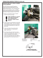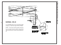
1
Setting the Standard With the
World's Most Valued Grinders.
605
ACCU - SHARP
AUTO-INDEX
SPIN / RELIEF
REEL MOWER GRINDER
This book consists of two manuals:
The OPERATORS MANUAL which contains all the
information on operating and doing routine daily
maintenance on this equipment.
The ASSEMBLY and SERVICE MANUAL which is
used by the maintenance department to install the
equipment and to do all maintenance except routine
daily maintenance.
1
Setting the Standard With the World's Most Valued Grinders.
W e are committed to:
Providing superior customer support, training,
and service.
Manufacturing the highest quality products at an
unequaled value.
Setting the industry standard by investing in
technological product innovation.
Manufacturing products specifically designed to
maintain original equipment manufacturers'
specifications.
Interacting with and supporting all original
equipment manufacturers.
2
605
ACCU - SHARP
AUTO-INDEX
SPIN / RELIEF
REEL MOWER GRINDER
OPERATORS
MANUAL
WARNING
You must thoroughly read and understand this manual
before operating the equipment, paying particular
attention to the Warning & Safety instructions.
3
6057955 (7-05)
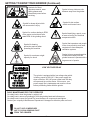
SAFETY INSTRUCTIONS
Safety Awareness Symbols are inserted into this
manual to alert you to possible Safety Hazards. Whenever you see these symbols, follow their instructions.
The Warning Symbol identifies special instructions
or procedures which, if not correctly followed, could
result in personal injury.
The Caution Symbol identifies special instructions
or procedures which, if not strictly observed, could
result in damage to or destruction of equipment.
1. KEEP GUARDS IN PLACE and in working order.
13. MAINTAIN GRINDER WITH CARE. Follow
instructions in Service Manual for lubrication and
preventive maintenance.
2. REMOVE WRENCHES AND OTHER TOOLS.
3. KEEP WORK AREA CLEAN.
14. DISCONNECT POWER BEFORE SERVICING,
or when changing the grinding wheel.
4. DON'T USE IN DANGEROUS ENVIRONMENT.
Don't use Grinder in damp or wet locations.
Machine is for indoor use only. Keep work area well
lit.
15. REDUCE THE RISK OF UNINTENTIONAL
STARTING. Make sure the switch is OFF before
plugging in the Grinder.
5. KEEP ALL VISITORS AWAY. All visitors should
be kept a safe distance from work area.
16. USE RECOMMENDED ACCESSORIES. Consult
the manual for recommended accessories.
Using improper accessories may cause risk of
personal injury.
6. MAKE WORK AREA CHILD-PROOF with
padlocks or master switches.
17. CHECK DAMAGED PARTS. A guard or other
part that is damaged or will not perform its
intended function should be properly repaired or
replaced.
7. DON'T FORCE THE GRINDER. It will do the job
better and safer if used as specified in this manual.
8. USE THE RIGHT TOOL. Don't force the Grinder
or an attachment to do a job for which it was not
designed.
18. NEVER LEAVE GRINDER RUNNING
UNATTENDED. TURN POWER OFF. Do not
leave grinder until it comes to a complete stop.
9. WEAR PROPER APPAREL. Wear no loose
clothing, gloves, neckties, or jewelry which may
get caught in moving parts. Nonslip footwear is
recommended. Wear protective hair covering to
contain long hair.
19. KNOW YOUR EQUIPMENT. Read this manual
carefully. Learn its application and limitations as
well as specific potential hazards.
20. KEEP ALL SAFETY DECALS CLEAN AND
LEGIBLE. If safety decals become damaged or
illegible for any reason, replace immediately.
Refer to replacement parts illustrations in Service
Manual for the proper location and part numbers of
safety decals.
21. DO NOT OPERATE GRINDER WHEN UNDER THE
INFLUENCE OF DRUGS, ALCOHOL, OR
MEDICATION.
10. ALWAYS USE SAFETY GLASSES.
11. SECURE YOUR WORK. Make certain that the
cutting unit is securely fastened with the clamps
provided before operating.
12. DON'T OVERREACH. Keep proper footing and
balance at all times.
4
SAFETY INSTRUCTIONS
IMPROPER USE OF GRINDING WHEEL MAY CAUSE
BREAKAGE AND SERIOUS INJURY.
Grinding is a safe operation if the few basic rules listed below are followed. These
rules are based on material contained in the ANSI B7.1 Safety Code for "Use, Care
and Protection of Abrasive Wheels". For your safety, we suggest you benefit from
the experience of others and carefully follow these rules.
DO
DON'T
1. DO always HANDLE AND STORE wheels in a
CAREFUL manner.
1. DON'T use a cracked wheel or one that HAS
BEEN DROPPED or has become damaged.
2. DO VISUALLY INSPECT all wheels before
mounting for possible damage.
2. DON'T FORCE a wheel onto the machine OR
ALTER the size of the mounting hole - if
wheel won't fit the machine, get one that will.
3. DO CHECK MACHINE SPEED against the
established maximum safe operating speed
marked on wheel.
3. DON'T ever EXCEED MAXIMUM
OPERATING SPEED established for the
wheel.
4. DO CHECK MOUNTING FLANGES for equal
and correct diameter.
4. DON'T use mounting flanges on which the
bearing surfaces ARE NOT CLEAN, FLAT
AND FREE OF BURRS.
5. DO USE MOUNTING BLOTTERS when
supplied with wheels.
6. DO be sure WORK REST is properly adjusted.
5. DON'T TIGHTEN the mounting nut
excessively.
7. DO always USE A SAFETY GUARD
COVERING at least one-half of the grinding wheel.
6. DON'T grind on the SIDE OF THE WHEEL
(see Safety Code B7.2 for exception).
8. DO allow NEWLY MOUNTED WHEELS to run
at operating speed, with guard in place, for at
least one minute before grinding.
7. DON'T start the machine until the WHEEL
GUARD IS IN PLACE.
8. DON'T JAM work into the wheel.
9. DO always WEAR SAFETY GLASSES or some
type of eye protection when grinding.
9. DON'T STAND DIRECTLY IN FRONT of a
grinding wheel whenever a grinder is started.
10. DON'T FORCE GRINDING so that motor
slows noticeably or work gets hot.
AVOID INHALATION OF DUST generated by grinding and cutting operations.
Exposure to dust may cause respiratory ailments. Use approved NIOSH or
MSHA respirators, safety glasses or face shields, and protective clothing.
Provide adequate ventilation to eliminate dust, or to maintain dust level below
the Threshold Limit Value for nuisance dust as classified by OSHA.
5
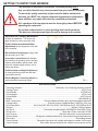
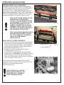
GETTING TO KNOW YOUR GRINDER
This machine is intended for reel mower reel blade grinding ONLY.
Any use other than this may cause personal injury and void the warranty.
To assure the quality and safety of your machine and to maintain the
warranty, you MUST use original equipment manufactures replacement
parts and have any repair work done by a qualified professional.
ALL operators of this equipment must be thoroughly trained BEFORE
operating the equipment.
Do not use compressed air to clean grinding dust from the machine.
This dust can cause personal injury as well as damage to the grinder.
Adjustable Reel Clamping Mechanisms
for ease of installation. Two chain vise
grips included to secure any size roller.
Positive Vertical and Horizontal Reel
Adjustments for fast alignment of the reel
in the machine.
Dial Indicator Setup Gauge to align reels
with accuracy up to .001".
Accessible Control Panel with independent switches for grinding motor, carriage
traverse with variable speed control, spin
drive with variable speed control, and a
safety stop button.
Positive Infeed and Height Adjustment
for exact positioning of the reel and measured metal removal.
Electro-Magnetic Traversing Switch for
easily adjustable traversing length.
FIG. 1
SPECIFICATIONS
Traversing Switches .................................................................... Solid state, non-contacting proximity switches
Carriage Travel .................................................................................................................................. 45"[115 cm]
Overall Width ................................................................................................................................. 79.5"[202 cm]
Overall Height .................................................................................................................................... 83"[211 cm]
Overall Depth ................................................................................................................................. 48.5"[124 cm]
Weight ........................................................................................................................................ 1290 lbs[585 kg]
Base Construction ............................................... Precision Machined heavy duty reinforced welded steel base
Carriage Rails ............................................................. Precision Ground, Hardened Steel 1.000 Dia. [25.4 mm]
Grind Head Motor ........................... 3/4 HP at 60 HZ, 5/8 HP at 50 HZ, 3450 RPM at 60 HZ, 2875 RPM at 50 HZ
Elevator ....................................................................................................................... 400 lbs. [180 kg] capacity
Spin Drive ............................................................ Reversible variable speed 0-380 RPM DC Gear Motor .20 Hp
Sound Level .............................................................................................. More than 75 Dba, Less than 95 Dba
Auto Traverse ...................................................................................... Belt drive with built in overload protection
Grinding Head ..................................... 90 degrees rotatable head with pin lock locations for grinding bedknives
Rail covers ........................................................................................................................... Telescoping bellows
Control System ..................................... Reversible Spin drive with variable spin speed or variable relief torque
Control System ........................................... Door safety interrupt switches and variable traverse speed control
6
GETTING TO KNOW YOUR GRINDER (Continued)
Symbols for Read
operators manual, wear
safety glasses and
disconnect power before
servicing.
Symbol to keep visitors a safe
distance away from the grinder.
Symbol for hot surface
which could cause burns.
Symbol for sharp object which
will cause serious injury.
Symbol for caution relating to RPM
of the motor and minimum safe
rated RPM of the grinding wheel.
Symbol identifying a panel, cover,
or area as having live electrical
components within.
Symbol for hearing
protection required when
operating this machine
Symbol that operators and people
in the close proximity must wear
respirators or have adequate
ventilation systems.
Symbol for maximum weight
capacity for winch
Symbol to keep exposed gasoline
or flammables away from the
grinder because it operates with a
large amount of sparks.
LOW VOLTAGE RELAY
The grinder is equipped with a low voltage relay which
is factory preset at 100 VAC. If the power supply line
does not deliver 100 VAC power under load, the relay
will open and trip out the starter. If this occurs, your
power supply line is inadequate and must be correct
before proceeding further with the grinder.
DAILY MAINTENANCE BY THE OPERATOR
On a daily basis, clean the grinder by wiping it off.
On a daily basis, remove all grinding grit from the grinding head and bellows area.
On a daily basis, inspect the grinder for loose fasteners or components and tighten.
Contact your company's Maintenance Department if damaged or defective parts are found.
DO NOT USE COMPRESSED
AIR TO CLEAN GRINDING DUST
FROM THE GRINDER.
7
GETTING TO KNOW YOUR GRINDER (Continued)
GETTING TO KNOW YOUR MACHINE
The following is an explanation of the machine
components you will be using when setting up reels
to grind on your new Spin Grinder. You should
familiarize yourself with each part as this grinder has
been engineered to spin and relief grind almost every
type and make of reel mower available today.
Adjustment of the various fixtures will be necessary
for different types of reels.
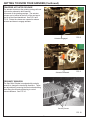
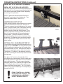
OVERHEAD MOWER CLAMP ASSEMBLY
Each overhead mower clamp assembly consists of
two rectangular bar clamps (top and bottom), which
also contain adjustable holding fixtures into which is
placed the mower clamps. These clamps will be
positioned on the overhead square bar as shown in
FIG. 2 and FIG 3. They are designed to lock into
place and not move during the grinding procedure.
Included are two sizes of clamp lips, normally the
smaller will be used. Also included are two sets of
clamp rods. Because of potential interference with
the front doors we supply two long and two short
clamp rods.
FIG. 2
Top Portion
Clamp Rod
Clamp Rod
Handwheel Assembly
Long Threaded
Knob Assembly
Clamp Lips
Bottom Portion
FIG. 3
ROLLER SUPPORTS
There are two roller supports that are mounted to the
square mounting bar so that the "V" faces the back
of the machine and the offset can be mounted high
as pictured or low. The rooler brackets can also face
upward with the offset either forward or to the rear.
See FIG. 4.
THE HARD KNOBS ON THE
SQUARE BAR MUST BE VERY
TIGHT OR THE REEL CAN LOOSEN
CAUSING POOR GRIND QUALITY.
FIG. 4
8
GETTING TO KNOW YOUR GRINDER (Continued)
CENTER MOUNTING BRACKETS
The centers mounting brackets consist of a
stationary center bracket and an adjustable center
bracket. The stationary bracket will normally be used on
the right hand side of the mounting bar when facing the
reel loading position. See FIG. 5. These centering fixtures
are used primarily on greens mowers and the OPTIONAL
Bedknife Attach Kit 6000555.
FIG. 5
OPTIONAL PULL GANG BRACKETS
The OPTIONAL Pull Gang Reel Mount Kit 18574
consists of a lower mounting bracket that fits over the
square tooling mounting bar and two threaded locking
screws. Attached to this is the upper "V" bracket that
cradle the reel hub when in position. There are three
vertical adjustments on this fixture, but will normally be
used in the upper hole position. See FIG. 6.
These brackets can be mounted on the square
mounting bar with offset either forward or backwards, but
the normal position will be with the "V" centered over
the bar or with the offset facing the back of the machine. The hold-down swing arm has an upper and
lower mounting position depending on mower hub size.
FIG. 6
The rear roller of the pull gang mowing unit attaches to
the roller supports as shown in FIG. 7.
Vice Grip Chain Clamps
9
FIG. 7
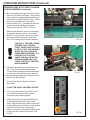
GETTING TO KNOW YOUR GRINDER (Continued)
TRAVERSE ACTUATOR RELEASE
The actuator that drives the grinding carriage left and
right can be released to allow manual
movement of the grinding carriage. The actuator
release arm is located at the front of the carriage to
the left of the infeed handwheel. See FIG. 8 and
FIG. 9. Rotate the release arm upward to release
actuator and down to engage actuator.
Actuator Engaged
Actuator Released
FIG. 8
FIG. 9
PROXIMITY SENSORS
The Spin Relief Grinder is equipped with proximity
sensors to change the traversing directions. These
are adjustable by loosening the star knob and sliding
them along the rail and retightening to control
traverse distance. See FIG. 10.
Proximity Sensor
FIG. 10
10
GETTING TO KNOW YOUR GRINDER (Continued)
GRINDING WHEEL AND GUARD FOR SPIN
GRINDING
Spin grinding requires a 1.00" wide [25.4 mm]
grinding wheel and a simple flat grinding wheel
guard. See FIG. 11.
GRINDING WHEEL AND FINGER - GUARD
ASSEMBLY FOR RELIEF GRINDING
FIG. 11
Relief grinding requires a 3/8" .375" [9.5 mm]
grinding wheel and a wheel guard that carries
the fixed relief finger and the moveable index
finger. See FIG. 12.
RELIEF GRINDING FINGER ADJUSTMENTS
The relief Index Finger Assembly has three
adjustments as follows:
FIG. 12
1. The index pin is adjustable in height
with the loosening of its locking setscrew.
The height of the finger can be raised to
Index
catch the next blade on small diameter
Pin
reels or it can be lowered to avoid
interference with the reel spider.
See FIG. 13.
2. The moveable finger has a knob to
limit the amount of back travel. The back
travel of the finger is limited so the reel
blade makes a smooth transition from
the moveable finger onto the fixed finger
without interferences. The fixed
finger is the working finger during the
grind. See FIG. 14.
Locking
Setscrew
FIG. 13
Moveable
Finger
Fixed
Finger
Travel
Limit Knob
3. The lock handle on the side of the
guard/carrier plate is an adjustment for
grinding wheel wear. Use this to hold the
fingers in the correct position to the
grinding wheel. See FIG. 15.
FIG. 14
Lock
Handle
FIG. 15
11
GETTING TO KNOW YOUR GRINDER (Continued)
Attach Fixture with
this Screw Knob
DIAL INDICATOR SET UP FIXTURE
The dial indicator set up fixture is designed to be
quickly mounted into position and/or quickly
removed.
The fixture is mounted to the front left corner of
the grinding head assembly as shown in FIG. 16.
When the fixture is not in use, it is quickly
removed and can be stored on the tool tray.
FIG. 16
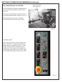
CONTROL PANEL
The control panel has 10 control switches and
knobs. See FIG 17. Details of the function of
each are shown on pages 13,14 and 15. Additionally, there are two circuit breakers on the
control panel. The 10 amp circuit breaker is to
protect the grinding motor circuit and the 4 amp
circuit breaker is to protect the spin drive circuit.
FIG. 17
12
GETTING TO KNOW YOUR GRINDER (Continued)
CONTROL PANEL COMPONENT IDENTIFICATION
Review the following control panel component descriptions before proceeding with the instructions
SYSTEM START SWITCH
Powers all control panel systems.
Pulls in the main magnetic starter.
NOTE: The guard doors must be shut and all
switches must be off for the machine to start.
SPIN DRIVE SWITCh
ON/OFF
Turns the spin drive motor ON/OFF.
Guard doors must be shut for the spin drive
to operate.
SPIN SPEED DIAL
RPM
Adjusts the speed of reel rotation when you
have the grind selector switch set at variable
speed spin.
GRIND SELECTOR SWITCH
Variable Speed Spin
Switch must be up to perform
spin grinding operations.
Variable Torque Relief
Switch must be down to perform
relief grinding operations.
13
GETTING TO KNOW YOUR GRINDER (Continued)
RELIEF TORQUE DIAL
Adjusts the Spin Drive Motor torque (the
torque holding the reel blade to the relief
finger) when Grind Selector Switch is set at
variable Torque Relief.
GRINDING WHEEL MOTOR SWITCH
ON / OFF
Turns the Grinding Wheel Motor on and off.
Guard doors must be shut for Grinding
Motor to operate.
SPIN DRIVE ROTATION SWITCH
Forward / Off / Reverse
This switch reverses the spin drive motor.
Toggle in middle is off position and stops rotation.
NOTE : Because the spin drive motor can mount on
either side of the reel rotation direction will vary.
THE MOTOR MUST COME TO A COMPLETE
STOP BEFORE CHANGING DIRECTIONS. IF
THE MOTOR DOES NOT COME TO A
COMPLETE STOP, SERIOUS DAMAGE TO
THE CONTROL MAY RESULT.
TRAVERSE MOTOR SWITCH
ON/OFF
Turns the traverse drive motor on and off.
14
GETTING TO KNOW YOUR GRINDER (Continued)
TRAVERSE SPEED DIAL - FT / MIN
Adjusts the speed of the left & right
movement of the grinding wheel
carriage.
EMERGENCY STOP BUTTON
Cuts all power to the control panel functions. Stops all
motors, including grinding motor, traverse motor, spin
motor, etc. To restore power, pull up on the button and
press the start button.
PUSHING THE EMERGENCY STOP BUTTON DOES NOT
STOP ALL POWER TO THE GRINDER. POWER IS STILL
DELIVERED TO THE INFEED SIDE OF THE MAGNETIC
CONTACTOR. DISCONNECT THE CORD AT THE WALL
OUTLET BEFORE PERFORMING SERVICE.
SAFETY INSTRUCTIONS
PLEASE TAKE SPECIAL NOTE OF THE FOLLOWING WARNING DECAL
LOCATED NEAR THE WINCH OF THE MODEL 605.
--WARNING-1. Lifting winch capacity 400 lbs. maximum.
2. Always have the lifting hooks securely
attached and balanced on the cutting unit
before lifting.
3. Stand well clear of the cutting unit when
winching into position. Guide with extended
arms only.
4. The winch is equipped with a safety
ratchet. Do not defeat or override this
safety feature.
5. Read warning label on winch handle and
the assembly and operating manual
before using the winch.
15
OPERATING INSTRUCTIONS
PREPARE MOWER FOR SHARPENING
Preparation of the mowing unit prior to sharpening.
It is recommended that the mowing unit to be sharpened is
thoroughly cleaned. Remove wheels and bed bar, if
possible from the reel. All bedknives must be ground
when reels are sharpened. Inspect, adjust and/or replace
any worn or damaged bearings. Make sure reel bearings
are adjusted properly so the reel turns easily by hand.
REELS WITH EXCESS TENSION ON THE
BEARINGS WILL BE EXTREMELY
DIFFICULT TO SPIN GRIND AND COULD
CAUSE DAMAGE TO THE REEL OR THE
SPIN DRIVE MECHANISM ON YOUR
GRINDER. NO MORE THAN 25 IN LBS.
MAXIMUM TORQUE LOAD TO ROTATE
THE REEL IS ALLOWED OR DAMAGE TO
THE SPIN DRIVE COULD OCCUR.
FIG. 18
REELS GROUND WITH BEARINGS WHICH
HAVE WEAR AND/OR FREE PLAY WILL
NOT HOLD DIAMETER, CYLINDRICAL
SHAPE, OR STRAIGHTNESS
SPECIFICATIONS.
INITIAL SET UP OF REEL SUPPORTS
A. The preferred method of mounting fairway units and greens
mower units is to set the rear roller on the roller supports
facing up with the offset either forward or back, depending
on mowing unit requirements. Chain clamp around the
roller and the tooling bar. See FIG. 18.
B. With greens mowers, you may use the centers
mounting brackets. See FIG. 19.
C. On ground drive fairway mowers with exposed hubs,
you should use the OPTIONAL Pull Gang Reel Mount Kit
18574. Normally they will be positioned in the top two
holes of the lower supports with the offset "V" facing the
rear of the machine. See FIG. 20.
Centering Pin
FIG. 19
Centering Bracket
NOTE: Because of the many different reels available
the position of the "V" bracket to the lower support can be
adjusted to three different height settings
and two offset positions.
FIRMLY TIGHTEN ALL LOCKING
KNOBS BEFORE GRINDING. ANY
LOOSENESS WILL ADVERSELY
AFFECT GRINDING QUALITY.
FIG. 20
16
OPERATING INSTRUCTIONS (Continued)
INITIAL SET UP OF SUPPORTS (Continued)
INITIAL SET UP OF ROLLER SUPPORTS
The roller support brackets should be placed facing up
with the V ribs 1 to 2" narrower than the width of the rear
roller with the offset either forward or back, depending
on mowing unit requirements.
NOTE: Tighten the side locking knob first so the
bracket is forced against the mounting bar. Then
tighten the bottom bracket. See FIG. 21.
CENTERS BRACKET SET UP
When mounting greens mower mowing units, centers
may be used to hold the mower unit. See FIG. 22.
To mount, measure the outside distance of the mower
frame. Using the center point of the square mounting
bar position the fixed centering bracket 1/2 that
distance on the left side and securely fasten. Then
place the adjustable centering bracket that distance
plus 1/4" on the right side of the mounting bar and
loosely fasten. It may be necessary to move this
bracket when lifting reel into place even though it can
be adjusted. The adjusting cone should be retracted
as far as possible as it will be easier to secure reels
when in place.
FIG. 21
OPTIONAL PULL GANG BRACKET SET UP
On ground drive mowing units with exposed hubs you
will be using the OPTIONAL Pull Gang Reel Mount Kit
18574, measure the distance from the outside of the
hubs and subtract one inch. Determine the middle of
the square mounting bar, by use of the winch cable.
Then place a "V" bracket 1/2 that distance on the left
side of the mounting bar and securely fasten use both
locking knobs.
FIG. 22
Now place a "V" bracket on the right side of the
mounting bar the same distance from the center point,
but loosely attach as it might have to be moved when
reel is lifted into place. The roller support brackets
should be placed 6 to 8" inside the reel supports with
the "V" facing the back of the machine and securely
fastened with both locking knobs. The "V's" have an
offset so they can be installed high or low depending on
the reel. See FIG. 23.
FIRMLY TIGHTEN ALL LOCKING
KNOBS BEFORE GRINDING. ANY
LOOSENESS WILL ADVERSELY
AFFECT GRINDING QUALITY.
FIG. 23
17
OPERATING INSTRUCTIONS (Continued)
LIFTING MOWING UNIT INTO POSITION WHEN
USING ROLLER SUPPORTS
Position the mowing unit behind the grinder on the floor so
the front of the mower faces towards the front of the
machine. Hook the reel elevator spreader bar onto the
mowing unit. The hooks on the bar should be spaced
evenly along the mowing unit, so they do not slip or slide
as it is being raised. See FIG. 24.
THE OPERATOR SHOULD BE
POSITIONED AWAY FROM THE
REEL. DO NOT STAND
UNDERNEATH THE REEL AS IT
IS BEING RAISED. GUIDE REEL
AT ARMS LENGTH.
FIG. 24
Slowly raise the mowing unit by cranking the winch handle
with the right hand and steadying the reel with the left
hand. Your left arm should be extended during the lifting
operation This will help keep the operator from under the
mower.
NOTE: The winch has a spring loaded handle that
automatically actuates a brake when the handle is
released. The winch clicks as it is being raised when this
brake is engaged.
Slowly move the reel into position and carefully lower the
cutting unit onto the roller supports. Firmly tighten both
locking knobs on the roller supports. Make certain the
spin drive can be attached to a drive device on the reel..
Do not connect at this time, just make sure that the
connections are close enough to attach at a later time.
When the reel roller is positioned correctly in the roller
supports, wrap one of the chain vise clamps around the
roller, and around the square tubing tooling bar. Firmly
tighten and repeat this step with the other chain vise
clamp around the other roller support.
LIFTING MOWING UNIT INTO POSITION WHEN
USING CENTER BRACKETS
Position the mowing unit as described above using roller
supports. Slowly raise the mowing unit into position and
insert the fixed centering pin into a
predetermined hole in the mowing unit frame. While
holding the mowing unit firmly against the fixed
centering pin, raise or lower the mowing unit so the
adjustable centering bracket can be moved and the cone
inserted in a corresponding hole in the opposite side of
mowing unit frame. Now very firmly tighten both locking
knobs on the adjustable bracket and then tighten the
adjustable centering pin locking knob. See FIG. 25.
18
FIG. 25
Lock Knob
Adjustable Center Knob
FIRMLY TIGHTEN ALL LOCKING
KNOBS BEFORE GRINDING. ANY
LOOSENESS WILL ADVERSELY
AFFECT GRINDING QUALITY.
THE ADJUSTABLE CENTER MUST
BE FIRMLY TIGHTENED INTO THE
REEL, BUT EXCESSIVE FORCE CAN
DISTORT THE REEL FRAME CAUSING
BINDING AND POOR QUALITY.
Make certain the spin drive can be attached to a drive
device on the reel. Do not connect at this time, just
make sure that the connections are close enough to
attach at a later time.
OPERATING INSTRUCTIONS (Continued)
LIFTING MOWING UNIT INTO POSITION WHEN
USING THE OPTIONAL PULL GANG
MOUNTING BRACKETS
Position the mowing unit as described on the previous
page using roller supports. See FIG. 26
Slowly raise the mowing unit, when the hub of the reel
has been raised above the top of the "V" bracket slowly
position the left side of the reel into the bracket and
lower until you make contact with the bracket.
Now reposition the right "V" bracket if necessary and
lower the reel completely into both brackets. Securely
tighten the right bracket using both locking knobs.
FIG. 26
NOTE: On reels that have a square or hexagon
shaped hub make sure that the surface of the hub is
against the flat machined surface of the "V" bracket.
Clamp Handle
When the reel is correctly positioned in the V-bracket,
swing the clamping handles into place and firmly lock
in place. See FIG. 27.
NOTE: The clamping handles have two mounting
positions for large and small hubs.
NOTE: Unless the elevator hooks interfere with the
reels ability to spin, leave the elevator hooks and
spreader connected to the reel with slight tension on
the wire cable.
FIG. 27
19
OPERATING INSTRUCTIONS (Continued)
LIFTING MOWING UNIT INTO POSITION WHEN
USING THE OPTIONAL PULL GANG
MOUNTING BRACKETS (CONTINUED)
There are two (2) roller supports that are mounted to
the square mounting bar so that the "V" faces the back
of the machine as pictured in FIG. 28A.
There are four (4) OPTIONAL long set screws on
these brackets which are used to hold the OPTIONAL
extender plates when it is necessary to move mower
roller back further to help expose the drive nut in the
reel. These set screws will also be used to attach the
chain vise clamps when reels are in position.
FIG. 28A
FIG. 28B
FIG. 28C
Position the roller supports so the reel roller is centered
on the two (2) supports and firmly lock in place.
NOTE: On some reels the "V" grooves of the roller
supports will be positioned on top of the support bar.
This application is used primarily for fairway and
greens mowers. See FIG. 28B.
Roller Brace Stud
If extender plates are necessary to move mowing unit
back further, simply pull the mowing unit back out of the
way and slide extender plate onto both long socket
head set screws and tighten down with 3/8-16 nuts and
3/8 lockwashers. See FIG. 28C.
MAKE SURE THAT THE ELEVATOR
CABLE IS ATTACHED TO THE REEL
AND THAT SOME TENSION IS ON
CABLE BEFORE PULLING REEL
BACK.
When the reel roller is positioned correctly in the roller
brace, wrap one of the chain vise clamps around the
roller, and around the stud on the roller brace. Firmly
tighten and repeat this step with the other chain vise
clamp around the other roller brace. See FIG. 29.
Vise Chain Clamps
FIRMLY TIGHTEN ALL LOCKING
KNOBS BEFORE GRINDING. ANY
LOOSENESS WILL ADVERSELY
AFFECT GRINDING QUALITY.
20
Support Bar
FIG. 29
OPERATING INSTRUCTIONS (Continued)
ATTACHING THE OVERHEAD CLAMPING ARMS
Your grinder is supplied with two lengths of clamp rods
and two sizes of clamping lips, determine which size of
clamp rod is appropriate for the mowing unit you are
grinding. Normally the shorter rod is used.
Overhead Clamps
NOTE: Using the long clamp rods on large reels may
cause an interference between the rods and the front
guard doors.
Determine which clamp lips to use in your grinding
application. You have three choices; First, the large lip
clamps which are primarily attached to the front rollers.
Second, the small lip clamps are primarily attached to
a mowing unit cross bar or a mounting lug or bolt.
Third, you can remove the clamping lips, turn the
clamp rods 90 degrees and attach the clamp rods
directly to the mowing unit using the hole on the end of
the clamp rod attached to a stud or bolt on the mowing
unit frame.
FIG. 30
Slide Bar Clamp
Loosen the two (2) screw handles on each overhead
clamp and move them to where the overhead clamp
rods with or without clamping lips can be attached to
the mowing unit. Tighten the clamping lips to the
mower, then securely tighten the two (2) locking
handles on each overhead clamp. See FIG. 30 and
FIG. 31.
The overhead clamps can be mounted with the
clamping rod above the tubing cross bar as shown in
FIG. 31 or they can be mounted with the clamp rod
under the tubing cross bar as shown in FIG. 32. It is
recommended to mount them under the tubing cross
bar whenever possible.
Top Portion
Clamp Rod
Before tightening the overhead clamps you must
correctly position the mowing unit. When using the
roller supports or the centers, you can pivot the cutting
unit with the overhead clamps. With the relief grinding
wheel and the relief guard with fingers installed, you
must pivot the cutting unit so you have clearance of the
relief finger to the frame, clearance of the next blade to
be relieved to the grinding wheel and clearance of the
grinding wheel to the front roller.
DO NOT TIGHTEN THE LEFT HAND
SLIDE ROD CLAMP WHERE RODS
ARE INSERTED INTO THE LOWER
PART OF THE CLAMP UNTIL REEL
HAS BEEN ALIGNED.
FIRMLY TIGHTEN ALL LOCKING
KNOBS BEFORE GRINDING. ANY
LOOSENESS WILL ADVERSELY
AFFECT GRINDING QUALITY.
Clamp Lips
Bottom Portion
Clamp Rod
Handwheel
Assembly
Long Threaded
Knob Assembly
FIG. 31
FIG. 32
21
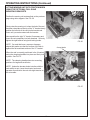
OPERATING INSTRUCTIONS (Continued)
ATTACHING THE VARIABLE SPEED SPIN
DRIVE UNIT TO THE REEL
When spin grinding, the reel should turn in the same
direction as the grinding wheel. See FIG. 33. The
normal position for the spin drive unit is on the right
side of the square mounting bar when viewing from the
mowing unit loading position of the machine.
Before positioning the spin drive unit, familiarize
yourself with the available adjustments and coupler/
drive assemblies.
FIG. 33
KNOB A-Adjusts the scissor bar to move the unit up and down.
KNOB B (2 EACH)-Allows the spin unit to be loosened and moved in and out.
KNOB C & D-Allow the spin assembly to be loosened from the
support bar frame and moved side to side.
Knob A
Knob B
Knob C Knob D
When positioning the spin unit it will be necessary to
complete several of the above adjustments to properly
align the spin unit to the reel.
34a.
34b.
34c.
34d.
Rubber Sleeve Coupler: This is placed in the
corresponding flange coupler already mounted
in the spin drive shaft.
Drive Coupler Assembly: This is mounted to
the rubber coupler.
Adapter Sleeve: Connects the rubber coupler
to the square drive adapter.
Square Drive Adapter: This is inserted into the
drive coupler adapter and should be able to be
moved approximately 2". It will be necessary to
move this when attaching reel to spin drive unit.
It is then inserted into any 1/2" square drive
socket. This square shaft has a groove
machined into it on the opposite end of the snap
ring. This groove is there to advise that you
have reached the maximum extension of the
square drive shaft. If you cannot connect to the
reel without extending past this groove, then the
spin unit must be repositioned on the tooling bar
(knobs C & D above).
FIG. 34
b. Drive Coupler Adapter
c. Adapter Sleeve
DO NOT EXTEND SQUARE SHAFT
PAST GROOVE, INSTEAD REPOSITION
d. Square Drive Adapter
SPIN UNIT.
Socket
a. Rubber Coupler FIG. 35
22
OPERATING INSTRUCTIONS (Continued)
Spin Drive Unit
NOTE: The 1/2" square drive socket that is places on
the reel when spin grinding is NOT included with the
grinder. You must purchase this from an appropriate
local supplier of tools. Many of today's reels have a
spline at the end of the reel shaft to receive the
hydraulic motor shaft. The cutting unit manufacturer
has adapters you can purchase to drive these reels.
The following procedures will make setting up the spin
drive unit easier.
1. Move spin drive unit close to the reel. Align the
shaft on the spin drive with the drive component on
reel by completing the necessary adjustments
discussed on the previous page.
2. Now slide the spin drive unit approximately 7" from
the reel drive coupling point and securely fasten to
the square mounting bar tightening both locking
knobs.
3. Place the proper 1/2" square drive socket or
adapter on the reel drive component and then insert
the square drive shaft into the socket. Place the
adapter sleeve over the drive shaft and insert the
drive coupler adapter assembly into it. Finally place
the rubber coupler onto the drive coupler adapter.
See FIG. 36.
4. By holding the square drive shaft firmly into position
with your left hand you will be able to move the
other components to the right and insert the
rubber coupler into the flange on the spin drive
unit. When this is done tighten the Tee Knob on
the adapter sleeve to hold all parts in place. See
FIG. 37.
5. Finally readjust the spin drive unit if it is not in
alignment.
Square Mounting Bar
FIG. 36
Spin Drive Scissor Bars
Adapter
6009052
NOTE: It is not necessary to have perfect alignment
Socket or
but it must be close enough so that the coupler
remains engaged and that excess torque is not applied Adapter
to the reel.
Square Drive
Adapter
6009051
Adapter Sleeve
3709584
Rubber Coupler
3709585
FIG. 37
When intalling large reels into the grinder there may not
be room to install the full spin drive adapter assembly.
The Spin Drive Adapter Assembly has been designed
so that you can remove the 6009051 Square Drive
Adapter and the 6009052 Adapter by loosening the two
1/4-20 x 3/8 Socket Setscrews. This will expose the
square end of 6009217 Drive Coupler Adapter. This
can then be short coupled to the reel. See FIG. 38.
FIG. 38
23
OPERATING INSTRUCTIONS (Continued)
In most cases, it is recommended to leave the
spreader bar and chains hooked up to the mowing
unit as an added safety precaution. The cable
should be winch tight to insure the chain, hook and
spreader bar will not become engaged with the reel
during sharpening.
REMOVING SPREADER BAR FROM REEL
If the hooks will not clear the spinning reel, then
remove the spreader bar and hooks from the
mowing unit. Place hooks over the top channel on
the boom and crank up excessive slack.
See FIG. 39.
FIG. 39
Attach Fixture with
this Screw Knob
DIAL INDICATOR SET UP FIXTURE
The dial indicator set up fixture is designed to be
quickly mounted into position and/or quickly
removed.
The fixture is mounted to the front left corner of the
grinding head assembly as shown in FIG. 40.
When the fixture is not in use, it is quickly removed
and can be stored on the tool tray.
FIG. 40
24
OPERATING INSTRUCTIONS (Continued)
REEL ALIGNMENT USING THE DIAL
INDICATOR SET UP GAGE ASSEMBLY
Overhead Clamp
Rod Adjusting Knob
A. Mount the set up gage into position on the left
front side of the grinding head assembly. The gage
assembly can be set on the roll pin on the grinding
head slide base. This will line up the tee knob with
the threaded hole in the casting for an easy install.
See FIG. 40.
B. The left side over head clamp rod adjusting knob
(See FIG. 41.) must be loose to allow the mower
assembly which is mounted on the mower support
bar to move freely when doing horizontal and
vertical adjustments.
The overhead clamp rods will generally be used
as described below:
1. If the mowing unit is mounted with the ground
roller clamped to the roller supports with the
chain vice clamps, because the geometry
does not offer enough stability or rigidity, the
overhead clamp rod on the fixed end (right
side in the operator's position) should be kept
tight.
2. If the mowing unit is mounted in centers and
only being stabilized by the overhead clamp
rods, then the clamp rod on the fixed end must
be kept tight.
3. If the mowing unit is clamped in the OPTIONAL
Pull Gang Reel Mount Kit 18574 V-brackets and Horizontal
the ground roller is clamped with chain vice
Locking Knob
clamps, then both overhead clamp rod
adjusting knobs can be loose.
FIG. 41
Vertical Adjusting
Screw
C. Loosen the two locking knobs on the cross slide
assembly on the left side of the square mounting
bar so that it can be adjusted in both the vertical
and horizontal plane. See FIG. 42.
Horizontal Adjusting
Screw
Vertical
Locking Knob
FIG. 42
25
OPERATING INSTRUCTIONS (Continued)
Alignment Rod
ALIGNING REELS IN THE
VERTICAL PARALLELISM PLANE
A. Move the grinding head assembly until the set up
fixture is approximately 1" from the right side of the Vertical
Parallelsim
reel. Lock the Knob A within approximately 1/8"
.125" (3MM) of center shaft of the reel. See FIG. 45.
B. Raise the indicator slide casting on the vertical
support so that the indicator rod can be extended
over the center shaft of the reel. See FIG.43 and 44.
C. Lower the indicator slide by turning the vertical
fine adjustment Knob B until the alignment rod
lightly touches the top of the reel center shaft.
See FIG. 47.
D. Pull rod back and lock Knob C. See FIG. 45.
Traverse to the other side of reel, same distance
from end. Loosen Knob C and extend alignment
rod. See FIG. 46.
E. If the left side is lower than the right, turn the
vertical adjusting grey handwheel in the cross slide
assembly clockwise raising the mounting bar and
the reel until the center shaft of the reel lightly
touches the extended indicator rod. See FIG. 35.
Knob C
Knob B
Top of Carrier Shaft
FIG. 43
Knob A
FIG. 44
FIG. 45
FIG. 46
Knob B
FIG. 47
26
OPERATING INSTRUCTIONS (Continued)
VERTICAL ALIGNMENT (Continued)
F. Take note of the grey knob so you know from where
you are starting. See FIG. 49. Now turn the
vertical adjusting grey handwheel an additional 1/2
revolution. This 1/2 revolution is to compensate for
the fact that as you adjust the left side, the right
side is also moving at a proportioned amount. This
should almost align your reel in the vertical
parallelism plane. See FIG. 49.
G. Move the alignment fixture back to the right hand
side of the reel and readjust the alignment rod so
that it lightly touches the top of reel center shaft.
H. Move is back to the left side to make sure the reel
is in correct vertical position. If not, move vertical
adjustment grey handwheel up or down so that it
just touches alignment rod on both sides. When it
does, retest right and left sides until the same.
I. If the left side of the reel is found to be higher than
the right, lower the mounting bar and reel until
alignment rod lightly touches the top of the reel
center shaft and then turn the vertical adjusting
grey handwheel an additional 1/2 revolution. This
1/2 revolution is to compensate for the fact that as
you adjust the left side, the right side is also moving
at a proportioned amount. This should line the reel
up accurately on both sides. Then continue with
procedures found in "G" and "H" above.
J. Now lock the grey vertical adjusting screw locking
knob. See FIG. 49.
Alignment Rod
FIG. 48
Orange Horizontal
Locking Knob
Vertical Grey
Adjusting Handwheel
NOTE: This alignment is not as critical as the horizontal
plane, but care should be taken on all reel set ups.
The accuracy to be within approximately .010".
NOTE: The pivot end of the support bar is pinned to
the frame permanently. The adjustable end can be
adjusted independently both vertically and horizontally.
CAREFULLY REVIEW THE CORRECT
IDENTIFICATION OF THE COLORED
LOCKING KNOBS IN FIG. 49 MAKE
CERTAIN YOU ARE LOCKING AND
UNLOCKING THE CORRECT
KNOBS.
Horizontal Orange
Adjusting Handwheel
Grey Vertical
Locking Knob
FIG. 49
27
OPERATING INSTRUCTIONS (Continued)
ALIGNING REELS IN THE
HORIZONTAL PARALLELISM
Inside Reel of Shaft
Horizontal
Parallelism
Alignment Rod
THIS IS A CRITICAL SET UP AND
CARE SHOULD BE TAKEN WHEN
MAKING THESE ADJUSTMENTS. IF
REEL IS OUT OF POSITION IN THE
HORIZONTAL PLANE, IT WILL BE
GROUND CONE SHAPED. SEE FIG. 56.
Outside of
Carrier Shaft
A. Move set up gauge on the right hand side of reel
approximately 1" from the end. See FIG. 51.
B. Lower the indicator slide casting on the vertical
support so the indicator rod can make contact with
the center of the reel shaft within approximately
1/16" .062" (1.5 MM) and lock Knob A. See FIG. 45.
Center shaft should be clean and free of rust where
rod makes contact. Now fine adjust using Knob B
until at the center of the center shaft of the reel.
See FIG. 47.
C. Now loosen Knob D on the indicator stop bar.
Holding the indicator rod firmly against the reel
shaft, move the indicator stop bar back, until no
contact is made with the indicator rod plunger.
Now move indicator stop bar forward until contact
is made and then an additional 1/2". This will set
the plunger at about its midpoint and allowing it to
move in both directions. See FIG. 53.
D. Now set the outer dial indicator to the "0" position.
Read and note the position of the smaller (.100)
dial. You must know this reading when setting up
the other side. Pull back and lock with Knob C.
See FIG. 45.
E. Move the alignment gauge to the left side of the
reel carefully retracting the indicator rod so as not
to damage or change setting. Set indicator rod on
the same position on the reel as on the other side,
that is 1" from the end and centered on the shaft.
See FIG. 50. Now read the dial indicator to
determine the distance the reel is out of position.
FIG. 50
FIG. 51
NOTE: Because the set up gauge is mounted to the
carriage, you can unlock the actuator drive system and
traverse manually from end to end.
Indicator Rod Plunger
When you pull the indictor rod back, there is a wing
screw ("C") to snug up so you do not have to hold the
rod in the back position.
FIG. 52
Indicator Stop Bar
Indicator Rod
T Knob
1/32"
28
FIG. 53
OPERATING INSTRUCTIONS (Continued)
ALIGNING REELS IN THE
HORIZONTAL PARALLELISM (Continued)
F. To adjust reel position first determine the
direction the reel has to move for alignment.
The direction that the reel will have to be
moved can be determined by pulling back on
the dial indicator stop bar and if the dial moves
back to the "0" position you will have to move
the reel towards you. If that cannot be done
the reel will have to be moved away from you.
There are two adjusting steps for final positioning of
the reel as follows:
1. With the reel set gauge still in the left hand
side of the reel, turn the orange horizontal
adjusting handwheel (FIG. 49) in the direction
required to match the initial indicator reading
on the right hand reel position. See FIG. 51.
2. Now travel farther by half the amount
already traveled.
The reason for this is that the square mounting bar
pivots on one end and is adjusted on the opposite
end. Anytime the adjusting end is moved to change
the left side dimension, the right side dimension is
also changing at a ratio to the left side. By over
compensating at the adjusting end you will
compensate for this movement and get the reel
aligned much faster.
29
OPERATING INSTRUCTIONS (Continued)
ALIGNING REELS IN THE
HORIZONTAL PARALLELISM (Continued)
Orange Horizontal
Locking Knob
Vertical Grey
Adjusting Handwheel
G. Now move the set up stand back to the right
side of the reel. Set indicator rod on the same
spot you used the first time and reset large dial
on "0". Make sure you read the setting on the
small scale and note. Then proceed with
paragraph "E" & "F" again. This should give final
adjustment. When you have done this
procedure a few times you will find this
procedure will become very easy.
IT IS ESSENTIAL THAT CARE IS
TAKEN WHEN SETTING THE
REEL UP IN THE HORIZONTAL
POSITIONS IN ORDER TO GRIND
IT INTO A CYLINDER SHAPE.
ANY MISALIGNMENT WILL
CAUSE YOU TO GRIND INTO A
CONE. SEE FIG. 56.
Horizontal Orange
Adjusting Handwheel
Grey Vertical
Locking Knob
FIG. 54
H. When the horizontal parallelism has been
adjusted to within .003" (.076 MM) end to end,
tighten the orange horizontal adjustment locking
knob See FIG. 54 and both overhead clamp
adjusting knobs. See FIG. 55. When tightening
the knob it is very important that you have the
dial indicator located at that side of the reel and
watch it as you tighten. It must not move in the
tightening process. After both knobs are tight,
recheck alignment.
Overhead Clamps
Slide Bar Clamp
FIG. 55
30
OPERATING INSTRUCTIONS (Continued)
CHECKING REEL FOR CONE SHAPE,
REEL ROUNDNESS, AND STRAIGHTNESS
OF REEL OUTSIDE DIAMETER.
BEFORE GRINDING-A. Before storing the set up gauge, it is very
effective to use it to check the ungrounded
reel to determine the amount the reel is
conical in shape and which end has the larger
diameter. See FIG. 56. Start with the set up
gauge at the right end of the reel. Loosen the
wing nut on the indicator stop bar, holding the
indicator rod firmly against one blade. See
FIG. 53. Pull the indicator stop bar back until
it clears the plunger then advance it forward
until it contacts the plunger and advances it 1/2
inch further. Lock in place. This sets the
plunger at its midpoint and allows adequate
movement in both directions. Set outer dial at
zero and note position of pointer on small dial.
Cone Shape
INCORRECT
Cylinder Shape
CORRECT
FIG. 56
B. Now move it to the left side of reel and indicate
the same blade. From the reading determine
the amount the reel is cone shaped. This
also determines high point for grinding.
Grinding of a reel must always start at the
high point.
FIG. 57
AFTER GRINDING-A. After grinding a reel, check the roundness on
each end of the reel and center before removing
ground reel. See FIG. 57. Loosen the wing
nut on the indicator rod firmly against one
blade. Pull the indicator stop bar back until
there is a 1/32" gap between it and the set
screw. This is to permit rotation of the reel
blades to ride on the domed anvil only. See
FIG. 58. At each location (left, right and
center) turn the reel by hand and observe the
indicator variations. All readings should be
within .002".
B. Straightness of reel outside diameter--Take
indicator readings at both ends of reel. Compare
readings between each end of reel for
straightness. All reading should be within .002".
C. Carefully remove the setup gage and store
it on tool tray.
Indicator Stop Bar
Indicator Rod Plunger
Indicator Rod
Wing Screw
1/32"
FIG. 58
31
OPERATING INSTRUCTIONS (Continued)
SETUP PROCEDURE FOR SPIN DRIVE
RPM VERSUS TRANSVERSE SPEED
SPIN DRIVE RPM
SPIN DRIVE RPM IS VERY IMPORTANT IN ACHIEVING A
QUALITY GRIND. USE CARE IN ESTABLISHING THE SPIN
DRIVE RPM, PER THE INSTRUCTIONS BELOW.
Generally, the Spin Drive RPM will be between 180 RPM (45%)
and 300 RPM (80%). The speed required to spin a specific reel is
dependant on reel diameter, the number of reel blades, and reel
hardness. For all reels, there is an optimum Spin Speed where
there is an AGGRESSIVE, yet smooth grind as you spin grind the
reel. Your objective is to spin grind the reel as aggressively and
as fast as possible while maintaining top quality.
It is recommended to start grinding each reel at a Spin Speed of
200 RPM (50%) and evaluate the RPM by adjusting higher and
lower to optimize the Spin Speed for that reel. If the Spin Speed
is incorrectly set, you can experience two problems, grinding
wheel dressing or grinding wheel resonance. Each of these
problems is explained below.
On some reels, especially small diameter high blade count reels
if the Spin Speed RPM is set to high, the reel can act as a dresser
to the grinding wheel. There can develop what appears to be a
very aggressive grind (as if the infeed has self infed) and then a
sudden stop of grinding with no grinding wheel to reel contact.
If this occurs, your Spin Speed was set to high and you effectively
dressed your grinding wheel.
Some reels have a resonant RPM where the reel goes into
harmonics with the grinding wheel and the resonance vibrates
the grinder and results in a very bad grind. By changing the Spin
Speed to a higher or lower RPM you will move out of the resonant
range.
After determining the best Spin Speed RPM for a reel, note the
RPM on a "Setup Chart" that you will make. By noting the
correct RPM, you will avoid evaluating the Spin Speed the next
time you grind the reel.
TRAVERSE DRIVE RPM
The Traverse Speed potentiometer is adjustable from approximately 5 feet per minute [1.5 meters per minute] to 35 feet per
minute [10 meters per minute]. It is recommended to grind
between 15 and 20 feet per minute [4 and 6 meters per minute].
Grinding at a slower traverse speed, 10 feet per minute
[3 meters per minute] as an example, will give a better finish but
will extend the grind cycle time. Grind finish versus grind cycle
time is controlled by the choice of the operator.
32
OPERATING INSTRUCTIONS (Continued)
GRINDING REEL INTO A TRUE CYLINDER
BY SPIN GRINDING
This ACCU-Sharp model 605 grinder is
equiped with two grinding wheels and two
grinding wheel guards. Prior to spin grinding
install or verify installation of the 1" (25 MM)
wide grinding wheel and the spin wheel guard
which has no fingers attached. See FIG. 59
A. Before you proceed any further, check all
knobs to insure they are tight.
FIRMLY TIGHTEN ALL LOCKING
KNOBS BEFORE GRINDING.
ANY LOOSENESS WILL
ADVERSELY AFFECT GRIND
QUALITY.
FIG. 59
B. There are three (3) lock handles for locking the
grinding wheel vertically. Two (2) on the base
for the adjusting arm locks and one for grinding
wheel vertical height adjustment locking screw.
See FIG. 60.
C. Position the height of the grinding wheel
center so that it is 0 to 1" below the reel
center. See FIG. 61.
D. Infeed the grinding wheel until it just makes
contact with a reel blade while rotating the reel
by hand. Now tighten the two locking
knobs on the locking arms and the locking
knob for the height adjustment screw. Back the
grinding wheel off so it just clears the reel.
Lock Handle
Adjusting Arms
(1) each side
Lock Handle
Vertical Adjustment
FIG. 60
Lock
0" to 1"
FIG. 61
33
OPERATING INSTRUCTIONS (Continued)
GRINDING REEL INTO A TRUE CYLINDER
BY SPIN GRINDING (Continued)
E. Move the grinding wheel back from the reel and
frame so it will clear at all points. Set proximity
stops so they line up approximately with the end
of the frame and tighten them securely. Adjust
the traverse speed knob to zero and turn
traverse switch to on. Increases the traverse
speed knob so the carriage will traverse
slowly across the reel. See FIG. 62 & 63.
When the carriage has come to a momentary
stop against proximity switch, turn traverse
switch off. In this position, check to see that
grinding wheel has cleared the end of the
reel. If not, readjust stop so that this happens.
FIG. 62
CAUTION, IF THE REEL FRAME
EXTENDS PAST THE REEL
ITSELF, MAKE SURE THE STOP
IS SET SO THAT THE GRINDING
WHEEL WILL NOT RUN INTO
FRAME WHEN GRINDING. IT IS
POSSIBLE THAT IN SOME
CASES THIS WILL MEAN THE
GRINDING WHEEL WILL NOT
CLEAR THE END OF THE REEL
WHEN GRINDING.
F. Repeat this procedure for the other side of the
reel. Then set the traverse speed dial to
"10" and let the carriage traverse back and forth
to make sure that the stops are set properly.
G. Move grinding carriage to the high side end of
the reel and stop carriage.
FIG. 63
Put the Grind Selector Switch to Variable
Speed Spin.
CLOSE THE FRONT AND REAR DOORS.
H. Turn on spin drive motor and check to see if
reel is spinning freely and that coupling
components are properly aligned.
I.
With the spin drive running at 200 RPM, turn
on grinding wheel motor on main control
panel. Verify that the spin rotation is the same
as the grinding wheel, clockwise, looking at the
right end of the reel from the operators
position. Now slowly infeed the grinding wheel
until it just make contact with the reel. See
FIG. 64.
FIG. 64
34
OPERATING INSTRUCTIONS (Continued)
GRINDING REEL INTO A TRUE CYLINDER
BY SPIN GRINDING (Continued)
J. Set traverse speed knob to approximately
"12", then turn on the traverse switch and
begin grinding. If reel is in bad condition,
traverse slower as more material can be
removed. Conversely, if the reel is in good
condition, speed can be increased.
MAXIMUM RECOMMENDED
STOCK REMOVABLE PER PASS
IS .008. NOTE: THE INFEED
HANDLE IS CALIBRATED IN
INCREMENTS OF .002 (.05 MM)
ON THE RING SCALE LOCATED
ON THE INSIDE OF THE INFEED
HANDLE.
K. If grinding wheel is only making contact in one
part of the reel, adjust the traverse stop so the
carriage traverses slightly further than the
contacted area. As you infeed and wheel
makes full contact in this area, move traverse
stop away 6 to 8". This will speed up the
grinding process of getting a cone shaped
reel into a true cylinder. See FIG. 65.
L. Spin grinding is completed when full contact
is made across the entire length of the reel
and the entire width of all blades and the cutting
edge is sharp. It is required to have a sparkout
to complete grinding the outside diameter to a
true diameter. For sparking out, the process is
to infeed the grinding head for approximately
.002 (.05 MM) stock removal (one line on the
ring scale) and let the grinding wheel sparkout.
For sparking out in grinding process, always
traverse the grinding head at least 20 passes
with no additional infeed. Set traverse at slow
speed on dial setting approximately 4 to 8 feet
per minute range for final grinding sparkout.
After sparkout, shut the grinder completely off.
FIG. 65
M. Verify the reel straightness and roundness. Install the
alignment gage. Index reel blade until you read the high
point on the indicator. Now loosen the wing screw and
set the indicator stop block to a 1/32" gap as shown in
FIG. 57 & 58.
Mark this blade as #1 and set the large dial of indicator
setting to "0", then check each blade for maximum and
minimum reading.
NOTE: This process refers to sparkout, but what
we are looking for is a near sparkout, approximately a
99% reduction in grinding sparks from normal grind.
Do not run sparkout until you have no sparks
because this could be an extremely extended
period.
Check each end of reel and at the center. After
becoming familiar with the process, you will not have to
check each reel.
IT IS VERY IMPORTANT IN SPIN
GRINDING THAT YOU THOROUGHLY
SPARKOUT AT THE END OF THE GRIND
CYCLE. THE DIFFERENCE BETWEEN
ACHIEVING .005 OR .003 TOTAL
INDICATOR READING IS ACCOMPLISHED
THROUGH PROPER SPARKOUT.
NOTE: Greatest accuracy and best finish is
obtained when reel is sparked out. Use your set up
gauge, prior to relief grinding to check the reels for
roundness. This is very important when first
learning the operation of your machine.
35
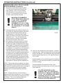
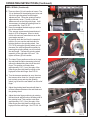
OPERATING INSTRUCTIONS (Continued)
REEL SPIRAL OR HELIX
When standing behind the mowing unit when the
mowing unit is sitting in normal position on the ground.
If the spiral is such that the right side of the blade cuts
before the left, it is a right hand lead in or a right hand
spiral reel. If the spiral is such that the left side of the
blade cuts before the right it is a left hand lead in or left
hand spiral reel. Most reels made today are right hand
spiral and are referred to as normal helix.
RELIEF GRINDING TO COMPLETE THE REEL
GRINDING PROCESS
A. This ACCU-Sharp model 605 grinder is equipped
with two grinding wheels and two grinding wheel
guards. Prior to relief grinding install or verify
installation of the 3/8" (9.5 MM) wide grinding wheel
and the relief wheel guard which has the relief and
index fingers attached. See FIG. 66.
B. Check to see if your mowing unit is normal or
reverse helix.
Back Stop Knob
FIG. 66
NOTE:
As you look into the guide finger on PAGE 38,
IT SHOWS THE NORMAL REEL HELIX. The
high point of the relief finger is on the right hand
side of the grinding wheel.
As you look into the guide finger on PAGE 39,
IT SHOWS THE REVERSE REEL HELIX. The
high point of the relief finger is on the right hand
side of the grinding wheel.
Most mowing units are normal helix.
C. Reset the Traverse Limit Proximity Switch
so the grinding wheel clears the reel at both
ends by approximately 1/16" (1.5 mm) or
the reel blade comes off the relief finger on
the right side. See FIG. 69 - 72.
FIG. 67
D. Set Grind Selector to variable torque relief.
(NOTE: The Spin Drive Rotation switch must be in
the OFF position when changing Grind Selector
switch.) Set Spin Drive Rotation switch to rotate
the reel into the stop finger, counterclockwise
(CCW) when looking at the right side. NOTE:
Relief torque reel rotation is always opposite spin
rotation.
FIG. 68
36
OPERATING INSTRUCTIONS (Continued)
REEL SPIRAL (Continued)
E. There are three (3) lock handles to loosen. Two
(2) on the base for the adjusting arm locks and
one for the grinding wheel vertical height
adjustment lock. Raise the grinding head up
approximately seven (7) turns so the reel
blade can rest on the reel guide finger. It will
be necessary to infeed the grinding wheel to
accomplish this. See FIG. 67.
F. Now you can adjust the back angle you wish to
put on the reel blade.
(The average recommended manufacturer's
angle is 20 to 40 degrees. When in doubt,
check with each reel manufacturer as to the
exact angle required.)
By looking down the reel from the operator's
position you can see the reel blade and its
relative position to the grinding wheel. See
FIG. 70. By raising the grinding wheel you will
decrease the relief angle and conversely by
lowering the grinding wheel you will increase
the relief angle. Traverse the grinding wheel
assembly to the right side of the reel. Retighten all three (3) lock handles.
FIG. 69
FIG. 70
G. The Index Finger position must be set to stop
the reel blade and allow traversing to the left
without the blade hitting the side of the relief
finger. This position must also allow
approximately 1/32" (1 mm) free play of the
index finger when the blade is resting on the
high point of the relief finger. See FIG. 68.
H. Turn the traverse speed pot to zero, then turn
the traverse drive motor on. Using the speed
pot to slowly move and stop the grinding
wheel, jog left until the reel blade is on the relief
finger.
FIG. 71
I.
Adjust the grinding head forward until there is
minimal clearance between the reel blade and
the grinding wheel.
J. Adjust the index finger positioning by rotating
the back travel adjust knob on the away side of
the grinding head. This position must allow
approximately 1/32" (1 mm) free play of the
index finger when the blade is resting on the
high point of the relief finger. See FIG. 66 - 68.
FIG. 72
.
37
For a NORMAL HELIX reel, the grinding wheel
will wear to match the angle of the reel blade.
NOTE: The square faced grinding wheel as
from the factory can be used for normal helix
reels and will wear to match the reel blade spiral.
OPERATING INSTRUCTIONS (Continued)
38
NORMAL HELIX
For a REVERSE HELIX reel, the grinding wheel
should be a wheel that has been used for NORMAL HELIX reels and has worn to match the
angle of the reel blade. The grinding wheel must
be reversed from a normal helix so the wheel
angle matches the angle as illustrated.
If you do not use a preworn grinding wheel so the
right side contacts first you may not relief grind
part of the last 3/8" [10 mm] of the blade.
NOTE: A wheel that has been worn to match a
normal helix can generally be removed and
reversed to grinder reverse helix reels.
OPERATING INSTRUCTIONS (Continued)
39
REVERSE HELIX
OPERATING INSTRUCTIONS (Continued)
K. CLOSE THE FRONT AND REAR GUARD DOORS
L. Turn the Torque Potentiometer to zero. Turn the Spin Drive
motor on.
NOTE: The spin drive will apply torque load against the
fingers.
Slowly turn the Relief Torque Potentiometer up to
approximately 15. NOTE: Free turning reels may need a
lower value than 15. Stiff reels or reels with a drive train
may need a higher torque than 15. Do not exceed 45 on the
relief torque potentiometer setting.
M. Jog the traverse all the way to the left prox switch watching
for proper clearance between the grinding wheel and the
blade. When the grinding head reaches the left prox, the
index finger should pop forward. See FIG. 70. The grinding
wheel should come off from the reel blade, but the reel
blade should remain on the fixed relief finger. See FIG. 69
Check for proper clearance between the index finger and
the front side of the blade on the return trip to the home
position. See FIG. 71. Also verify clearance between the
index finger and the reel blade support spiders.
N. Stop the traverse in home position and check for a proper
blade index. See FIG. 72. The traverse drive control is
factory set with a two second dwell time before it reverses
the carriage travel. This is to allow time for the reel to rotate
and the index finger to catch the next blade. If necessary
the dwell time can be adjusted (refer to Control Board
Potentiometer Adjustments section on Pages 23 in the
Assembly and Service Manual).
O. Allow the grinder to traverse down and back to verify
everything is properly set up. Turn the traverse
potentiometer to zero once the home position is reached.
P. Turn on the Grinding Wheel Motor.
Q. Turn on the traverse speed pot to a proper grinding speed.
Slowly infeed the grinding wheel until you are able to grind
the full length of the reel blade evenly. You can infeed
between .005" to .012" at a time. Be sure you have ground
all the blades before infeeding further.
NOTE: Traverse speed should be approximately 15 fpm. If you
are removing a small amount of stock on initial infeeds, faster
traverse speeds are suggested. If you are removing a large
amount of stock on later infeeds, slower traverse speed may
be required.
WHEN YOU HAVE SUCCESSFULLY COMPLETED THE SPIN
GRIND AND RELIEF GRIND ON A GIVEN MOWING UNIT
TYPE, THEN MEASURE AND COMPLETE THE SETUP
CHART ON PAGE 41.
40
REEL MAKE,
MODEL &
HEIGHT OF CUT
REAR
TOOLING
MOUNT
TYPE
REAR
TOOLING
MOUNT
POSITION
OVERHEAD
CLAMP
MOUNT
TYPE
REEL SETUP CHART
SPIN
OVERHEAD OVERHEAD SPIN
TRAVERSE NOTES
SPIN
SPEED
CLAMP ROD DRIVE
CLAMP
SPEED
SPEED
DISTANCE
MOUNT
POSITION SETTING SETTING SETTING
POSITION
Note: These dimensions will vary due to reel position in
frame, reel dia., height of cut, roller position, etc.
Use these values as a guide only.
REEL SETUP CHART
41