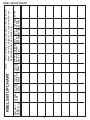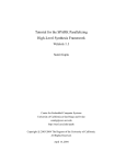
1
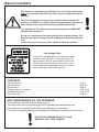
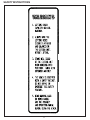
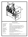
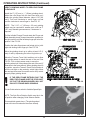
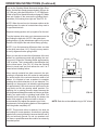
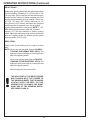
Setting the Standard With the
World's Most Valued Grinders.
ACCU-PR0 632
SPIN RELIEF
GRINDER
This book consists of two manuals:
The OPERATORS MANUAL which contains all the
information on operating and doing routine daily
maintenance on this equipment.
The ASSEMBLY and SERVICE MANUAL which is
used by the maintainence department to install the
equipment and to do all maintenance except routine
daily maintenance.
1
Setting the Standard With the World's Most Valued Grinders.
We ar
e committed to:
are
Providing superior customer support, training,
and service.
Manufacturing the highest quality products at an
unequaled value.
Setting the industry standard by investing in
technological product innovation.
Manufacturing products specifically designed to
maintain original equipment manufacturers'
specifications.
Interacting with and supporting all original
equipment manufacturers.
2
ACCU-PR0 632
SPIN RELIEF
GRINDER
OPERATORS
MANUAL
3
6327953 (11-05)
SAFETY INSTRUCTIONS
Safety Awareness Symbols are inserted
into this manual to alert you to possible
Safety Hazards. Whenever you see these
symbols, follow their instructions.
The Warning Symbol identifies
special instructions or procedures
which, if not correctly followed,
could result in personal injury.
The Caution Symbol identifies special instructions or procedures which, if not
strictly observed, could result in damage
to or destruction of equipment.
1. KEEP GUARDS IN PLACE and in working
order.
12. DON'T OVERREACH. Keep proper footing and
balance at all times.
2. REMOVE WRENCHES AND OTHER
TOOLS.
13. MAINTAIN GRINDER WITH CARE. Follow
instructions in Service Manual for lubrication and
preventive maintenance.
3. KEEP WORK AREA CLEAN.
14. DISCONNECT POWER BEFORE SERVICING,
or when changing the grinding wheel.
4. DON'T USE IN DANGEROUS ENVIRONMENT.
Don't use Grinder in damp or wet locations.
Machine is for indoor use only. Keep work area
well lit.
15. REDUCE THE RISK OF UNINTENTIONAL
STARTING. Make sure the switch is OFF before
plugging in the grinder.
5. KEEP ALL VISITORS AWAY. All visitors
should be kept a safe distance from work area.
16. USE RECOMMENDED ACCESSORIES. Consult
the manual for recommended accessories. Using
improper accessories may cause risk of personal
injury.
6. MAKE WORK AREA CHILD-PROOF with
padlocks or master switches.
7. DON'T FORCE THE GRINDER. It will do the job
better and safer if used as specified in this
manual.
17. CHECK DAMAGED PARTS. A guard or other
part that is damaged or will not perform its
intended function should be properly repaired or
replaced.
8. USE THE RIGHT TOOL. Don't force the grinder
or an attachment to do a job for which it was not 18. KNOW YOUR EQUIPMENT. Read this manual
designed.
carefully. Learn its application and limitations as
well as specific potential hazards.
9. WEAR PROPER APPAREL. Wear no loose
clothing, gloves, neckties, or jewelry which may 19. KEEP ALL SAFETY DECALS CLEAN AND
get caught in moving parts. Nonslip footwear is
LEGIBLE. If safety decals become damaged or
recommended. Wear protective hair covering to
illegible for any reason, replace immediately.
contain long hair.
Refer to replacement parts illustrations in Service
Manual for the proper location and part numbers
10. ALWAYS USE SAFETY GLASSES.
of safety decals.
11. SECURE YOUR WORK. Make certain that the
cutting unit is securely fastened with the clamps
provided before operating.
20. DO NOT OPERATE THE GRINDER WHEN
UNDER THE INFLUENCE OF DRUGS,
ALCOHOL, OR MEDICATION.
4
SAFETY INSTRUCTIONS
IMPROPER USE OF GRINDING WHEEL MAY CAUSE
BREAKAGE AND SERIOUS INJURY.
Grinding is a safe operation if the few basic rules listed below are followed. These rules are based on material
contained in the ANSI B7.1 Safety Code for "Use, Care and Protection of Abrasive Wheels". For your safety,
we suggest you benefit from the experience of others and follow these rules.
DON'T
DO
1. DO always HANDLE AND STORE
wheels in a careful manner.
1. DON'T use a cracked wheel or one that HAS BEEN
DROPPED or has become damaged.
2. DO VISUALLY INSPECT all wheels before
mounting for possible damage.
2. DON'T FORCE a wheel onto the machine OR
ALTER the size of the mounting hole--if wheel won't
fit the machine, get one that will.
3. DO CHECK MACHINE SPEED against the
established maximum safe operating speed
marked on wheel.
3. DON'T ever EXCEED MAXIMUM OPERATING
SPEED established for the wheel.
4. DON'T use mounting flanges on which the bearing
surfaces ARE NOT CLEAN, FLAT AND FREE OF
BURRS.
4. DO CHECK MOUNTING FLANGES for equal
and correct diameter.
5. DO USE MOUNTING BLOTTERS when supplied
with wheels.
5. DON'T TIGHTEN the mounting nut EXCESSIVELY.
6. DO be sure WORK REST is properly
adjusted.
6. DON'T grind on the SIDE OF THE WHEEL (see
Safety Code B7.2 for exception).
7. DO always USE A SAFETY GUARD COVERING
at least one-half of the grinding wheel.
7. DON'T start the machine until the WHEEL GUARD
IS IN PLACE.
8. DO allow NEWLY MOUNTED WHEELS to run at
operating speed, with guard in place, for at least
one minute before grinding.
8. DON'T JAM work into the wheel.
9. DON'T STAND DIRECTLY IN FRONT of a
grinding wheel whenever a grinder is started.
9. DO always WEAR SAFETY GLASSES or some
type of eye protection when grinding.
10. DON'T FORCE GRINDING so that motor slows
noticeably or work gets hot.
AVOID INHALATION OF DUST generated by grinding and cutting operations. Exposure
to dust may cause respiratory ailments. Use approved NIOSH or MSHA respirators, safety
glasses or face shields, and protective clothing. Provide adequate ventilation to eliminate
dust, or to maintain dust level below the Threshold Limit Value for nuisance dust as
classified by OSHA.
5
TABLE OF CONTENTS
This machine is intended for grinding the reel of reel type mower units
ONLY. Any use other than this may cause personal injury and void the
warranty.
To assure the quality and safety of your machine and to maintain the
warranty, you MUST use original equipment manufactures replacement
parts and have any repair work done by a qualified professional.
ALL operators of this equipment must be thoroughly trained BEFORE
operating the equipment.
Do not use compressed air to clean grinding dust from the machine. This
dust can cause personal injury as well as damage to the grinder. Machine
is for
indoor use only. Do not use a power washer to clean the machine.
Low Voltage Relay
The grinder is equipped with a low voltage relay which
is factory preset at 100 VAC. If the power supply line
does not deliver 100 VAC power under load, the relay
will open and trip out the starter. If this occurs, your
power supply line is inadequate and must be correct
before proceeding further with the grinder.
CONTENTS
Daily Maintenance ..................................................................................................................... Page 6
Safety Warnings ........................................................................................................................ Page 4-8
Specifications ............................................................................................................................ Page 9
Getting to Know Your Grinder .................................................................................................... Page 10-16
Operating Instructions ............................................................................................................... Page 17-30
Reel Setup Chart ....................................................................................................................... Page 32
DAILY MAINTENANCE BY THE OPERATOR
On a daily basis, clean the machine by wiping it off.
On a daily basis, remove all grinding grit from the grinding head and bellows area.
On a daily basis, inspect the machine for loose fasteners or components.
Contact your company's Maintenance Department if damaged or defective parts are found.
DO NOT USE COMPRESSED AIR TO CLEAN
GRINDING DUST FROM GRINDER.
6
SAFETY INSTRUCTIONS
PLEASE TAKE SPECIAL NOTE OF THE FOLLOWING WARNING DECALS
LOCATED ON THE FRONT OF THE GRINDER, THE WINCH BOOM OR LIFT
AND THE FRONT TOOLING BAR OF THE ACCU-Pro 632
Symbol to keep exposed gasoline
or flammables away from the
grinder because it operates with a
large amount of sparks.
Symbol for maximum weight
capacity for winch/Lift
Symbol for Read operators
manual, wear safety
glasses and disconnect
power before servicing.
Symbol to keep visitors a safe
distance away from the grinder.
Symbol for hot surface which could
cause burns.
Symbol for sharp object which will
cause serious injury.
Symbol identifying a panel, cover,
or area as having live electrical
components within.
Symbol for caution relating to RPM
of the motor and minimum safe
rated RPM of the grinding wheel.
Symbol that operators and people
in the close proximity must wear
respirators or have adequate
ventilation systems.
Symbol for hearing
protection required when
operating this machine
7
SAFETY INSTRUCTIONS
8
SPECIFICATIONS
Traversing Switches
Carriage Travel
Overall Width
Overall Height
Overall Depth
Weight
Base Construction
Carriage Rails
Grind Head Motor
Winch/Lift Capacity
Spin Motor
Sound Level
Auto Traverse
Rail Covers
Control System
Solid state, non-contacting proximity switches.
38" [97 cm]
71" [181 cm]
71" [181 cm] - To Top of Frame ( 85" [220 cm] - To Top of Boom)
48" [122 cm] - (71" [181 cm] - With Lift in Down Position)
1490 lbs. [676kg] 1770 lbs shipping weight [803 kg] - (Boom Model)
1670 lbs. [758kg] 1950 lbs shipping weight [885 kg] - (Lift Model)
Precision heavy duty reinforced welded steel base
Precision Ground, Hardened Steel - 1.000 Dia. [25.4 mm]
1HP AC Motor, 3450 RPM
400 lbs. maximum [180 kg]
.20 HP Fan Cooled Variable Speed DC Motor
More than 75 Dba, Less than 95 Dba
Quick release belt drive traverse - Variable Speed DC Motor
Telescoping bellows
*Safety power lift and front door interlock switches
*Reversible Spin drive for variable speed Spin or variable torque Relief Functions
*Solid State variable speed traverse control.
9
GETTING TO KNOW YOUR GRINDER (Continued)
CONTROL PANEL COMPONENT IDENTIFICATION
Review the following control panel component descriptions before proceeding with the instructions
SYSTEM START SWITCH
Powers all control panel systems.
Pulls in the main magnetic starter.
GRIND SELECTOR SWITCH
Variable speed spin
Switch must be up to perform
spin grinding operations.
Variable Torque Relief
Switch must be down to perform
relief grinding operations.
SPIN DRIVE ROTATION SWITCH
Forward / Off / Reverse
This switch reverses the spin drive motor.
Toggle in middle is off position and stops
rotation.
NOTE : Because the spin drive motor can
mount on either side of the reel rotation
direction will vary.
SPIN SPEED DIAL
RPM
Adjusts the speed of reel rotation when you
have the grind selector switch set at variable
speed spin.
10
GETTING TO KNOW YOUR GRINDER (Continued)
RELIEF TORQUE DIAL
Adjusts the Spin Drive Motor
torque (the torque holding the reel
blade to the relief finger) when
Grind Selector Switch is set at
variable Torque Relief.
GRINDING WHEEL MOTOR SWITCH
On / Off
Turn the Grinding Wheel Motor on and off.
Guard doors must be shut for Grinding
Motor to operate.
INFEED JOG SELECTOR
Slow / Fast
Switch up is fast infeed speed &
switch down is slow infeed speed.
Note: When the grinding motor is
on, the infeed will always be in
slow mode.
INFEED JOG SELECTOR
Up / Down
Moves the Grinding Wheel up or
down.
11
GETTING TO KNOW YOUR GRINDER (Continued)
TRAVERSE MOTOR SWITCH
Turns the traverse drive motor ON/OFF.
TRAVERSE SPEED DIAL - FT / MIN
Adjusts the speed of the left & right
movement of the Grinding wheel
(Carriage).
EMERGENCY STOP BUTTON
Cuts all power to the control panel `
functions. Stops all motors, including
grinding motor, traverse motor, infeed
stepper motor, etc.
PUSHING THE EMERGENCY STOP BUTTON DOES NOT STOP
ALL POWER TO THE GRINDER. POWER IS STILL DELIVERED
TO THE INFEED SIDE OF THE MAGNETIC CONTACTOR.
DISCONNECT THE CORD AT THE WALL OUTLET BEFORE
PERFORMING SERVICE.
SPIN MOTOR SWITCH
Turns the Spin drive motor ON/OFF
Guard doors must be shut for Spin
Motor to operate.
12
GETTING TO KNOW YOUR GRINDER (Continued)
FRONT AND REAR MOWER MOUNTING
The mowing unit is placed into the machine with the
rear roller on the V rear clamp support bracket and front
roller held with the front tooling clamps. The front tooling
bar clamps can be moved from side to side along the
tooling so they can be positioned as far apart as
possible on varying widths of reels (loosen knob on lower
part of bar mounting bracket in FIG. 1). You also have
the ability to adjust the height (loosen knob on horizontal
bracket in FIG. 1) and the forward and backward
position (loosen knob on roller clamp bracket in FIG. 1).
This allows the mower unit to be set up with the bottom
of the reel approximately flush to the table and the
center of the reel aligned to the reel positioner gage (see
section on reel positioner gage below). When the front
tooling clamps and mower unit are in proper position
lock in place by tightening knobs. The rear roller clamp
is positioned with the V rear clamp support bracket
centered on the rear roller. The height of the rear roller
clamp can be adjusted down by simply ratcheting the
unit down and adjusting up by pulling up on the release
lever and then sliding the unit up. To lock the front tooling
clamps rotate the roller clamp up and lock in place with
the quick release pin. Then turn the t-knobs clockwise
until roller is firmly held in place. See FIG. 1.
FIG.1
REEL POSITION GAGE
The Reel Position Gage is used to obtain proper in and
out (fore and aft) positioning of the mower unit. Mount
the Reel Position Gage onto the table with the ears
butted against gaging surface of the table. See FIG. 2.
You then position the center of the reel within the slot in
the Position Gage. This is an approximate starting point
for setup purposes. There are special reels and unique
situations that may require the reel to not be set on the
center of the flag. This flag is for setup reference only.
FIG. 2
TRAVERSE ACTUATOR RELEASE
The belt that drives the grinding carriage left and right
can be released to allow manual movement of the
grinding carriage. The clamp release arm is located at
the front of the carriage under the Carriage Proximity
Flag Bracket. See FIG. 3 Rotate the release arm up to
release actuator and down to engage actuator.
BELT CLAMP
RELEASE ARM
FIG. 3
13
GETTING TO KNOW YOUR GRINDER (Continued)
TRAVERSE PROXIMITY SENSORS
The Traverse Proximity Sensors are used to change the
traversing directions for the grinding carriage and are
mounted in the Proximity Brackets located in front of the
Traverse Base. See FIG. 4. The sensors are mounted with
wave washers to allow a left and right sliding movement
with out loosening the sensor nuts. There is a light on the
sensor which lights up when the switch is activated.
GRINDING HEAD POSITIONS SPIN/RELIEF
The Finger and Body Assembly of the grinding head
rotates on the Grinding Head Housing to change positions
between spin grinding and relief grinding. To change the
position of the finger and Body Assembly you have to pull
out the Plunger Pin on the left side of the Grinding Head
Housing. See FIG. 5. When you are going to perform spin
grinding operations the Finger and Body Assembly must be
rotated clockwise (looking at it from the right). This rotates
the fingers out of the reel blade path. See FIG. 5 When you
are going to perform relief grinding operations the Finger
and Body Assembly must be rotated counter clockwise. This
rotates the finger into position to touch and control the reel
blades. See FIG. 6
TRAVESE LEFT LIMIT
PROXIMITY SENSOR
TRAVERSE RIGHT
LIMIT PROXIMITY
SENSOR
TRAVERSE BASE STANDING ALONE
WITHOUT DUST PROTECTION
COMPONENTS
FIG. 4
INDEX FINGER ADJUSTMENTS
The Finger and Body Assembly includes two fingers. See
FIG. 5. The Fixed Relief Finger is equivalent to the Relief
Fingers on other relief grinders. When relief grinding the
Movable Index Stop Finger moves from the Relief Finger
Side (back side) of the reel blade when traversing from right
to left to the grinding wheel side (front side) of the reel blade
when traversing from left to right. This feature allows the
fully Automatic Relief function. When performing relief
grinding operations it is important to have the Index Stop
Finger adjusted properly.
STEP 1: Once you have the Grinding Head positioned with
a reel blade resting on the Fixed Relief Finger high point,
you want about 1/32" [.8mm) to 1/16" [1.5mm] free play of
the Index Finger behind the reel blade. The Index Finger is
spring loaded to the up position. To check free play, push
down on the Index Finger. See FIG. 6. To make this
adjustment you have to first turn the Index Lock Handle
counter clockwise to unlock the adjustable Index Lever. See
FIG. 6 If there is no free play of the Index Finger you want to
rotate the Adjustable Index Lever clockwise. If there is more
than 1/16" [1.5 mm] free play you want to rotate the
Adjustable Index Lever counterclockwise. When the Index
Finger is in proper position rotate the Index Lock Handle
clockwise to lock the Adjustable Index Lever.
The Index Stop Pin is height adjustable. It should be adjusted
to catch the reel blade and still leave enough clearance to
the reel spider after the relief is ground to the reel spider
after the relief is ground to the depth required.
NOTE: The reason for the 1/32" (1 mm) clearance is so
that the high point of the Relief Finger is acting as the guide
during the relief grind cycle. The Index Stop Finger acts as
a guide onto the tapered ramp of the Relief Finger.
14
FIG. 5
GETTING TO KNOW YOUR GRINDER (Continued)
STEP 2: With the down limit of the Index Finger
properly set you may have to adjust the up limit of the
Index Finger for 5" (127 mm) diameter reels with
reverse helix blades.
The up travel limit is restricted to keep the Index
Finger in the reel blade index path. This is done to
properly catch the next blade when indexing or to
allow clearance between the back side of the Index
Finger and the front side of the blade when the
grinding carriage is making its return trip to the home
position. If the Index Finger has problems catching
the next blade turn the Index Finger T-knob
counterclockwise. If there isn't enough clearance
between the back side of the Index Finger and the
front side of the reel blade turn the Index Finger
T-Knob clockwise. See FIG. 6. Adjust the T-knob in
by 1/8" (3mm) into the hole opening so the up travel
is restricted. Check the up and down swing of the
Index Finger for clearance on both sides of the reel
blade for the relief grind.
FIG. 6
NOTE: This adjustment is factory set for maximum
up travel of the index finger for 1/4" (6mm) reel blade
thickness. This adjustment should only be needed
for small diameter reels, such as 5" [127 mm]
diameter reels with reverse helix blades.
This adjustment is functional only on cutting units with
thin blades on small reels.
ALIGNMENT GAGE
A properly ground reel should be cylindrical. All taper
must be ground out of the reel. To ensure the reel will
be ground correctly it MUST be aligned precisely prior
to grinding. The digital alignment gage is used for
accurate reel setup. The same gage is used for
setting both the horizontal and vertical alignment
within thousands of an inch. The digital gage allows
you to measure one end of the reel by extending the
slide rail until you make contact with the center hub
of the reel . See FIG. 7. You then reset the gage to
zero, retract the slide rail and measure the other end
of the reel. The reading on the digital scale tells you
exactly how far the reel is out of alignment.
NOTE: The digital gage is capable of reading
alignment to four decimal places (.0000). For reel
alignment this accuracy is not required and will greatly
extend alignment time. Alignment should be done to
three decimal places (.000).
NOTE: Gage can be set for both inch and metric readout.
15
FIG. 7
GETTING TO KNOW YOUR GRINDER (Continued)
RELIEF ANGLE ADJUSTMENT
You should always make sure the Reel Positioner
Adjuster is at its mid point before you set up a reel to
grind. This will allow to adjust the relief angle by
approximately 8 degrees in both directions. You can
find the mid point by turning the Reel Positioner
Adjuster clockwise, using the 5/16" Allen Key included,
until it makes contact with the stop pin (make sure
Adjuster is turned completely counter clockwise
before you start). Then turn the Reel Positioner
Adjuster counterclockwise again 1/2 the number of
revolutions you counted. See FIG. 9.
As an example, if the angle you obtain from initial set
up is 30 degrees, you can increase the angle as far
as approximately 38 degrees by rotating the Reel
Positioner Adjuster clockwise until it makes contact
with the stop pin. (NOTE: If 38 degrees is not enough
relief angle you can move the reel forward one notch
on the front tooling horizontal bracket. Make sure you
reset the Reel Positioner Adjuster to the mid point
again before you move the reel, and always realign
reel if it is moved. You can decrease the angle as far
as approximately 22 degrees by rotating the Reel
Positioner Adjuster counter clockwise until it makes
contact with the stop plate. (NOTE: If 22 degrees is
still too much relief angle, you can move the reel back
one notch on the front tooling horizontal bracket.)
16
FIG. 9
OPERATING INSTRUCTIONS
PREPARE MOWING UNIT FOR SHARPENING
When preparing a cutting unit for sharpening, follow
the cutting unit manufacturers recommendations for
proper maintenance. It is recommended that the reel
to be sharpened is thoroughly cleaned. Remove wheels
and bed bar, if possible, from the reel. All bedknives
must be ground when reels are sharpened. Inspect,
adjust and/or replace any worn or damaged bearings.
Make sure reel bearings are adjusted properly so the
reel turns easily by hand.
Because this grinder mounts the reel using the rear
roller, and front roller if applicable, the bearings must
be in good repair with no freeplay. The front and rear
rollers must be properly aligned parallel to the reel
prior to grinding.
REELS WITH EXCESS TENSION ON
THE BEARINGS WILL BE EXTREMELY
DIFFICULT TO SPIN GRIND AND COULD
CAUSE DAMAGE TO THE REEL OR THE
SPIN DRIVE MECHANISM ON YOUR
GRINDER. NO MORE THAN 25. IN. LBS
MAXIMUM TORQUE LOAD TO ROTATE
THE REEL IS ALLOWED OR DAMAGE TO
THE SPIN DRIVE COULD OCCUR.
FIG. 10
LIFTING REEL INTO POSITION
Boom Model
Position the reel in front of the grinder on the floor so
the front of the mower faces towards the front of the
machine. See FIG. 10 Hook the winch spreader bar
onto the reel. The clamps on the bar should be spaced
evenly along the mower, so they do not slide as the
mower is being raised.
FIG. 11
THE OPERATOR SHOULD BE
POSITIONED AWAY FROM THE
REEL. DO NOT STAND
UNDERNEATH THE REEL AS IT IS
BEING RAISED. GUIDE REEL AT
ARMS LENGTH.
Rear Lift Model
Lift or roll the reel onto the rear ramp so the front of the
mower faces towards the front of the machine. See
FIG. 12. Raise the lift until even with table. Move reel
onto grinder table and close the rear ramp.
FIG. 12
17
OPERATING INSTRUCTIONS (Continued)
INSTALL REEL
Move the reel to the approximate position, having the
rear roller on the rear clamp support bracket, and front
roller on front roller clamps. See FIG. 11.
MAKE SURE GRINDING WHEEL IS LOW
ENOUGH TO CLEAR THE REEL. YOU
CAN LOWER THE GRINDING WHEEL BY
DEPRESSING THE INFEED JOG BUTTON
DOWN.
Position front roller clamps as far out as possible to the
ends of the front roller, and center on the machine. See
FIG. 11.
FIG. 13
Set the vertical height of the clamps so the bottom of
the reel is flush to 3/8" (10 mm) above the table
surface. See FIG. 13.
Set the fore and aft position of the front clamps with
the reel Position Gage. Place the reel position gage
against gaging surface. See FIG. 14. You want to align
the center of the reel within the slot of the position gage.
THE HORIZONTAL SCALES AND VERTICAL
TOOLING SCALES MUST MATCH (LEFT AND
RIGHT) FOR PROPER ALIGNMENT.
For greensmower reels, the 3 1/2" (8 mm) diameter
grinding wheel must clear the front roller V-bracket by
approximately 1/4" (6mm).
FIG. 14
Make certain the reel is parallel to the front edge of the
table. Lock down with front clamps and rear clamp. See
FIG. 15 & 16.
FIRMLY TIGHTEN ALL LOCKING
KNOBS BEFORE GRINDING.
ANY LOOSENESS WILL ADVERSELY AFFECT GRINDING
QUALITY.
FIG. 16
FIG. 15
18
OPERATING INSTRUCTIONS (Continued)
ALIGN THE REEL
NOTE: When measuring to the reel center shaft always
make sure you are contacting an area free of dirt and grass.
FORWARD & BACKWARD
MOUNTING HOLES
HORIZONTAL ALIGNMENT
Install the horizontal extension bracket onto the carriage front
dowel pin and lock in place with knob. See FIG. 17.
Install the digital alignment gage onto the horizontal
extension bracket pointing at the center of the reel shaft and
lock into place with knob. See FIG. 18.
NOTE: The horizontal extension bracket is vertically
adjustable so the digital gage can be positioned to avoid reel
frame members, etc. The mounting of the vertical slide to
the horizontal weldment has two additional mounting holes
so the vertical slide can be tipped forward or back, again to
avoid reel frame members, etc. See FIG. 17.
Loosen the two locking handles on the pivot assembly on
the right side of the traverse base, so that it can be adjusted
in both the vertical and horizontal plane. See FIG. 19.
LOCK KNOB
HORIZONTAL EXTENSION
BRACKET
FIG. 17
FRONT
DOWEL PIN
First, measure the left side of the reel as far to the left as
possible with the digital alignment gages, making sure the tip
of the gage is centered on the reel center shaft. Set the gage
to zero, then move the gage and measure the right side at
the same distance from reel centerline as the left side. Do
not rotate the reel shaft except for a minimum amount to
clear the gage when taking measurements. Adjust the
orange horizontal handwheel. See FIG. 19. First note the
amount the reel is out of alignment. Then, with the digital
gage still on the right side of the reel, turn the orange
horizontal handwheel in the direction required until the gage
reads zero. Now continue turning the handwheel until the
gage reads the then full amount of the offset again. Repeat
the process until alignment is within .002" (.05 mm). Lock
the orange horizontal locking handle when done.
Example: If the reel center shaft is off .085 left to right, turn
the handwheel from .085 to zero and then continue to turn
until it reads .085 additional on the other side
of zero.
FIG. 18
TRAVERSE BASE STANDING ALONE
WITHOUT DUST PROTECTION
COMPONENTS
ORANGE HORIZONTAL
The reason for this is that the traverse frame
pivots on the left end and is adjusted on
the right end. Anytime the adjusting end
is moved to change the right side
dimension, the left side dimension is also
changed at a ratio to the right side. By over
compensating at the adjusting end you will compensate
for this movement and get the reel aligned much faster.
LOCKING HANDLE
GREY VERTICAL
HANDWHEEL
Aligning the reel to a value less than .002 (.05 mm) will not
improve the quality of the reel grind and will extend the
alignment time. DO NOT ALIGN THE REEL ANY
CLOSER THAN .002 (.05 mm).
Remove the gage. Remove the horizontal extension bracket
and store it on the mount located on the outside of the right
side grinder leg.
ORANGE HORIZONTAL
HANDWHEEL
GREY VERTICAL
LOCKING HANDLE
FIG. 19
19
OPERATING INSTRUCTIONS (Continued)
VERTICAL ALIGNMENT
Install the digital alignment gage vertically on the
carriage front dowel pin and pointing at the center of
the reel shaft. Lock into place with knob. See FIG. 20
First, measure the left side of the reel as far to the
left as possible, set the gage to zero, then measure
the right side, at the same distance from reel
centerline as the left side. See FIG. 21. Do not rotate
the reel shaft except for a minimum amount to clear
the gage when taking measurements. Adjust the
grey vertical handwheel. See FIG. 19. First note the
amount the reel is out of alignment. Then, with the
digital gage still on the right side of the reel, turn the
orange horizontal handwheel in the direction required
until the gage reads zero. Now continue turning the
handwheel until the gage reads the then full amount of
the offset again. Repeat until alignment is within .002"
(.05 mm).
LOCK KNOB
ALIGNMENT GAGE
FIG. 20
Example: If the reel center shaft is off .085 left to right,
turn the handwheel from .085 to zero and then
continue to turn until it reads .085 additional on the other
side of zero.
The reason for this is that the traverse frame pivots on
the left end and is adjusted on the right end. Anytime
the adjusting end is moved to change the right side
dimension, the left side dimension is also changed at
a ratio to the right side. By over compensating at the
adjusting end you will compensate for this movement
and get the reel aligned much faster.
Aligning the reel to a value less than .002 (.05 mm) will
not improve the quality of the reel grind and will extend
the alignment time. DO NOT ALIGN THE REEL ANY
CLOSER THAN .002 (.05 mm).
Lock the grey vertical locking handle when done.
Remove and store the gage on the mount located on
the outside of the right side of the grinder.
FIG. 21
20
OPERATING INSTRUCTIONS (Continued)
ATTACHING THE VARIABLE SPEED SPIN DRIVE
UNIT TO THE REEL
The spin drive unit attaches to the end of the reel shaft
or a drive system component. Consult the cutting unit
manufacturer for proper spin drive placement and
attachment. Determine which side to mount the spin
drive. This will generally be the same drive system
component used for backlapping. See FIG. 22.
Attach the spin drive unit onto the appropriate side.
When spin grinding, the reel should turn in the same
direction as the grinding wheel. See FIG. 23.
FIG. 22
Before positioning the spin unit you should familiarize
yourselves with the available adjustments and coupler/
drive assemblies. See FIG. 24.
KNOB A-Adjust the scissor bar to move the unit up and down.
KNOB B--(2 each)
Allows the spin unit to be loosened and moved in and
out.
KNOB C & D-Allow the spin assembly to be loosened from the
support bar frame and moved side to side.
When positioning the spin unit it will be necessary to
complete several of the above adjustments to properly
align the spin unit to the reel.
FIG.23
FIG. 24
21
OPERATING INSTRUCTIONS (Continued)
The coupler/drive assembly includes:
RUBBER SLEEVE COUPLER: This is placed in
the corresponding flange coupler already mounted
in the spin drive shaft. See FIG. 25.
DRIVE COUPLER ADAPTER ASSEMBLY: This
is mounted to the rubber coupler.
ADAPTER SLEEVE: Connects the rubber coupler
to the square drive adapter.
SQUARE DRIVE ADAPTER: This is inserted into
the drive coupler adapter and should be able to be
moved approximately 2" (51 mm). It will be
necessary to move this when attaching reel to spin
drive unit. It is then inserted into any 1/2" square
drive socket. This square shaft has a groove
machined into it on the opposite end of the snap
ring. This groove is there to advise that you have
reached the maximum extension of the square drive
shaft. If you cannot connect the reel without
extending past this groove, then the spin unit must
be repositioned on the tooling bar (knobs C & D).
NOTE: The 1/2" square drive socket that is placed on the reel when spin
grinding is NOT included with the grinder. You must purchase this from the
appropriate local supplier of tools. Some mowing units do not have a hex to
use for driving with a socket. Several adapters are available from the grinder
manufacturer. Additionally, you will have to make custom adapters for some
mowing units.
DO NOT EXTEND SQUARE SHAFT PAST
GROOVE, INSTEAD REPOSITION SPIN UNIT.
The following procedures will make setting up the spin drive unit
easier.
1. Move spin drive unit close to the reel. Align the shaft on the spin drive
with the nut on reel by completing the necessary adjustments
discussed on the previous page.
2. Now slide the spin drive unit approximately 7" (18 cm) from the reel
drive coupling point and securely fasten to the square mounting bar
tightening both locking knobs. (Knobs C & D)
3. Place the proper 1/2" square drive socket or adapter on the reel drive
nut and then insert the square drive shaft into the socket. Place the
adapter sleeve over the drive shaft and insert the drive coupler adapter
assembly into it. Finally place the rubber coupler onto the drive
coupler adapter. See FIG. 22
4. By holding the square drive shaft firmly into position with your left hand
you will be able to move the other components to the right and insert
the rubber coupler into the flange on the spin drive unit. When this is
done tighten the T-Knob on the adapter sleeve to hold all parts in place.
5. Finally readjust the spin drive unit if it is not in alignment.
NOTE: It is not necessary to have perfect alignment but it must be
close enough so that the coupler remains engaged and that excess
torque is not applied to the reel.
22
FIG. 25
OPERATING INSTRUCTIONS (Continued)
SETUP PROCEDURE FOR SPIN DRIVE
RPM VERSUS TRANSVERSE SPEED
SPIN DRIVE RPM
SPIN DRIVE RPM IS VERY IMPORTANT IN ACHIEVING
A QUALITY GRIND. USE CARE IN ESTABLISHING THE
SPIN DRIVE RPM, PER THE INSTRUCTIONS BELOW.
Generally, the Spin Drive RPM will be between 180 RPM
(45%) and 380 RPM (100%). The speed required to spin a
specific reel is dependant on reel diameter, the number of
reel blades, and reel hardness. For all reels, there is an
optimum Spin Speed where there is an AGGRESSIVE, yet
smooth grind as you spin grind the reel. Your objective is to
spin grind the reel as aggressively and as fast as possible
while maintaining top quality.
It is recommended to start grinding each reel at a Spin
Speed of 200 RPM (50%) and evaluate the RPM by
adjusting higher and lower to optimize the Spin Speed for
that reel. If the Spin Speed is incorrectly set, you can
experience two problems, grinding wheel dressing or
grinding wheel resonance. Each of these problems is
explained below.
On some reels, especially small diameter high blade count
reels if the Spin Speed RPM is set to high, the reel can act
as a dresser to the grinding wheel. There can develop what
appears to be a very aggressive grind (as if the infeed has
self infed) and then a sudden stop of grinding with no
grinding wheel to reel contact. If this occurs, your Spin Speed
was set to high and you effectively dressed your grinding
wheel.
Some reels have a resonant RPM where the reel goes into
harmonics with the grinding wheel and the resonance
vibrates the grinder and results in a very bad grind. By
changing the Spin Speed to a higher or lower RPM you will
move out of the resonant range.
After determining the best Spin Speed RPM for a reel, note
the RPM on the "Set-up Chart" in the "NOTES" section.
See page 33. By noting the correct RPM, you will avoid
evaluating the Spin Speed the next time you grind the reel.
TRAVERSE DRIVE RPM
The Traverse Speed potentiometer is adjustable from
approximately 5 feet per minute [1.5 meters per minute] to
35 feet per minute [10 meters per minute]. It is
recommended to grind between 15 and 20 feet per minute
[4 and 6 meters per minute].
23
OPERATING INSTRUCTIONS (Continued)
VERIFY GRINDING WHEEL TO REEL END FRAME
CLEARANCE
Install the 5" (127 mm) x 1 " (25mm) grinding wheel.
Adjust the relief finger with the front hand knob so it
clears the grinding wheel diameter (about 1/32" [0.8
mm]). Turn knob clockwise to move finger out and
counter clockwise to move finger in. See FIG. 27.
NOTE: The 3 1/2" x 1" (88 mm x 25 mm) grinding
wheel may be required for smaller reels, such as 5"
(127 mm) diameter greensmowers, if clearance is
required.
Pull the left side Plunger Pin and rotate the Finger and
Body Assembly down (forward toward the operator) to
the spin position until the left side plunger pin locks into
position. See FIG. 28.
FIG. 27
Position the index finger down and locked (pin in), with
right side locking index finger pin. See FIG. 28
Move the grinding wheel up to within at least 1/8" (3
mm) of reel by depressing the Infeed Jog button up.
Move the Traverse Travel Limit switches out to allow
the grinding wheel to reach the end of the reel. See
FIG. 29. Turn on the traverse motor to move the
grinding wheel until it has cleared the end of the reel (if
clearance to the frame allows). When grinding wheel is
in position, move the Traverse Travel Limit switches in
until the red light on the proximity switch lights. Allow
the carriage to traverse from end to end to verify switch
properly stops grinding wheel.
IF THE REEL FRAME EXTENDS PAST THE
REEL ITSELF, MAKE SURE THE STOP IS SET
SO THAT THE GRINDING WHEEL WILL NOT
RUN INTO FRAME WHEN GRINDING.
FIG. 28
Put the Grind selector switch to Variable Speed Spin.
NOTE: The Spin Drive Rotation Switch must be in the
off position when changing Grind Selector Switch.
Close and latch guard doors. (The grinding wheel
motor will not work unless the doors are closed).
FIG. 29.
24
OPERATING INSTRUCTIONS (Continued)
Turn on the Grinding Wheel Motor and the Spin Drive
Motor. Set the Spin speed at approximately 200 rpm for
10" (254 mm) reels and 300 rpm for 5" (127 MM) reels.
(Refer to Spin Drive Speed information on page 23). Make
sure spin rotation is the same as the grinding wheel clockwise (CW) looking from right end. See FIG. 30.
NOTE: When the reel turns in the same rotation as the
grinding wheel, the point of contact where they meet is
in opposite directions.
Depress infeed jog button until you spark off on the reel.
Turn the traverse drive motor on to traverse across the
reel finding the high side. NOTE: If the grind starts
getting heavier, jog the infeed down again until you can
travel the full length of the reel without heavy grinding.
FIG. 30
NOTE: If you find excessive differences from one side
to the other (more than 1/16 [1.5 mm]) you may want to
re-verify alignment before going further.
When you are able to travel the full distance of the reel
without any problems proceed with grinding the reel.
You want to infeed the Grinding Wheel approximately
.005" at a time. This is measured by the calibration ring
on the infeed motor. (See FIG. 31). Allow the Grinding
Wheel to travel back and forth across the reel 2 to 3
times before infeeding further.
When enough material has been removed, the spin
grinding is completed when full contact is made across
the entire length of the reel and the entire width of all
blades. It is required to have a sparkout to complete
grinding the outside diameter to a true diameter. For
sparking out, the process is to infeed the grinding head
for approximately .002 stock removal (two lines on the
ring scale) and let the grinding wheel sparkout. For
sparking out in grinding process, always traverse the
grinding head an adequate number of times to get finish
quality you require with no grinding head infeed. Set
traverse at slow speed on dial setting, the slower, the
better finish, approx. 8 feet per minute or slower is
recommended, but adjust the speed to your finish
requirements, for final grinding sparkout. After sparkout,
shut the grinder completely off.
NOTE: This process refers to sparkout, but what we
are looking for is near sparkout, a reduction in grinding
sparks from normal grind which assures that the reel is
fully and uniformly ground. Do not run sparkout until
you have no sparks because this could be an extremely
extended period.
25
FIG. 31
NOTE: Each line on the calibration ring is .001" infeed.
OPERATING INSTRUCTIONS (Continued)
RELIEF GRIND
Replace the grinding wheel with the appropriate wheel
for relief grinding. Generally a 5" (127 mm) Dia. x 3/8"
(10 mm) wide, will be used. As the reel diameter gets
smaller and the number of blades increases the relief
grinding wheel diameter must get smaller. That is why
a 5" Dia. (127 mm) x 3/8" (10mm) wide and a 3 1/2"
Dia. (88 mm) x 3/8" (10mm) wide wheel are furnished
with the grinder. As a general rule, use the largest
grinding wheel practical to relief grind. NOTE: 5" (127
MM) diameter greensmower reels with 11 blades
require a 3.5" (89 mm) diameter or smaller grinding
wheel. Adjust the relief guide finger with the front hand
knob so it slightly misses the smaller grinding wheel
diameter (about 1/32" [1 mm]).
REEL SPIRAL
Check to see if your mowing unit is normal or reverse
helix.
NOTE: As you look into the guide finger on PAGE 29,
IT SHOWS THE NORMAL REEL HELIX. The
high point of the relief finger is on the right hand
side of the grinding wheel.
As you look into the guide finger on PAGE 30,
IT SHOWS THE REVERSE REEL HELIX. The
high point of the relief finger is on the right hand
side of the grinding wheel.
Most mowing units are normal helix.
THE HIGH POINT OF THE RELIEF FINGER
MUST ALWAYS BE AT THE CORNER OF
THE GRINDING WHEEL THAT IS MAKING
CONTACT WITH THE REEL. ON THIS
GRINDER THAT IS ALWAYS THE RIGHT
HAND SIDE OF THE GRINDING WHEEL.
SEE PAGES 29 AND 30.
26
27
NOTE: The square faced grinding wheel as from
the factory can be used for normal helix reels and
will wear to match the reel blade helix.
For a NORMAL HELIX reel, the grinding wheel
should wear to match the angle of the reel blade.
NORMAL HELIX
Right Side of Wheel
Must Contact First
New Straight Wheel
Prefered Dressing
Actual Grinding Wheel
Contact Point
Matching Angle
OPERATING INSTRUCTIONS (Continued)
28
NOTE: A wheel that has been worn to match a normal
helix can generally be removed and reversed to grinder
reverse helix reels.
If you do not dress the grinding wheel so the right
side contacts first you may not relief grind part of
the last 3/8" [10 mm] of the blade.
For a REVERSE HELIX reel, the grinding wheel
should be dressed to match the angle of the reel
blade. It is recommended that a slightly larger
angle is dressed on the wheel so the right side
of the wheel is contacting the blade prior to the
left side as shown. The grinding wheel will then
wear to a match.
REVERSE HELIX
OPERATING INSTRUCTIONS (Continued)
OPERATING INSTRUCTIONS (Continued)
Reset the Traverse Limit Proximity Switch so the grinding
wheel clears the reel at both ends by approximately 1/16"
(1.5 mm).
Pull the left side plunger pin and rotate the Finger and
Body Assembly up (back, away from the operator) into
the relief position until the left side plunger pin locks into
position. See FIG. 32.
Pull the right side locking index finger pin to release the
index finger and rotate the handle into the retracted
position. See FIG. 32.
Set Grind Selector to variable torque relief. (NOTE: The
Spin Drive Rotation switch must be in the OFF position
when changing Grind Selector switch.) Set Spin Drive
Rotation switch to rotate the reel into the stop finger,
counterclockwise (CCW) when looking at the right side.
NOTE: Relief torque reel rotation is always opposite spin
rotation.
With the traverse in home position, jog the grinding head
up while manually rotating the reel until the index finger
touches the blade.
NOTE: The Index Finger position must be set to stop the
reel blade and allow traversing to the left without the blade
hitting the side of the relief finger. This position must also
allow approximately 1/32" (1 mm) free play of the index
finger when the blade is resting on the high point of the
relief finger. See FIG. 32.
Turn the traverse speed pot to zero, then turn the traverse
drive motor on. Using the speed pot to slowly move and
stop the grinding wheel, jog left until the reel blade is on
the relief finger. Adjust the index finger positioning by
loosening the Index Lock Handle and rotating the index
adjust lever on the right side of the grinding head*. See
FIG. 32. When this is completed, lock it into position by
tightening the index lock handle. Continue to jog the
grinding head up until there is minimal clearance between
the reel blade and the grinding wheel.
29
FIG. 32
OPERATING INSTRUCTIONS (Continued)
Turn the Spin Drive motor on.
NOTE: The spin drive will apply torque load against
the fingers.
Set the Relief Torque Potentiometer at approximately
15. NOTE: Free turning reels may need a lower value
than 15. Stiff reels or reels with a drive train may need
a higher torque than 15. Do not exceed 45 on the
relief torque potentiometer setting.
Jog the traverse all the way to the left watching for
proper clearance between the grinding wheel and the
blade. Check for proper clearance between the index
finger (after releasing from blade at far left position)
and the front side of the blade on the return trip to the
home position. Also verify clearance to the reel blade
support spiders.
Stop the traverse in home position and check for a
proper blade index. The traverse drive control is
factory set with a two second dwell time before it
reverses the carriage travel. This is to allow time for
the reel to rotate and the index finger to catch the next
blade. If necessary the dwell time can be adjusted
(refer to Control Board Potentiometer Adjustments
section on Pages 22-24 in the Assembly and Service
Manual).
At this point, you can adjust the relief angle by turning
the Reel Positioner Adjuster. See FIG. 33. You can
increase the relief angle approximately 8 degrees by
rotating the Reel Positioner Adjuster clockwise. You
can decrease the relief angle approximately 8 degrees
by rotating the Reel Positioner Adjuster
counterclockwise.
Close and latch doors.
Turn on the Spin Drive Motor (should already be on)
an the Grinding Wheel Motor.
Turn on the traverse speed pot to proper grinding
speed. Slowly infeed grinding wheel until you are able
to grind the full length of reel evenly. You can infeed
between .005" to .012" at a time. Be sure you have
ground all the blades before infeeding further.
NOTE: Traverse speed should be approximately 15
fpm. If you are removing a small amount of stock on
initial infeeds, faster traverse speeds are suggested.
If you are removing a large amount of stock on later
infeeds, slower traverse speed may be required.
30
FIG. 33
--This page intentionally left blank for note taking purposes.--
31
TRAVERSE NOTES
TOOLING SPIN DRIVE GRINDING SPIN
SPIN
PROGRAM TOOLING TOOLING
REEL MAKE,
MOUNTING
WHEEL
HORIZONTAL
SPEED
DISTANCE
SPEED
VERTICAL
TORQUE
NAME
MODEL &
SIDE R or L DIA.
SCALE
APART
SETTING SETTING SETTING
SCALE
HEIGHT OF CUT
REEL SETUP CHART
Note: These dimensions will vary due to reel position in
frame, reel dia., height of cut, roller position, etc.
Use these values as a guide only.
REEL SETUP CHART
32