1
StorageWorks Array Controller
HSJ40 Array Controller Operating
Firmware V1.2 Release Notes
Order Number: EK–HSFAM–RN. E01
This document summarizes certain features and limitations of the
HSJ40 Array Controller Operating Firmware (HSOF) V1.2 that are not
covered elsewhere in the documentation and contains instructions for
installing the firmware.
Digital Equipment Corporation
Maynard, Massachusetts
November, 1993
While Digital Equipment Corporation believes the information included in this document is correct
as of the date of publication, it is subject to change without notice and should not be construed as
a commitment by Digital Equipment Corporation.
The software described in this document is furnished under a license and may be used or copied
only in accordance with the terms of such license.
No responsibility is assumed for the use or reliability of software on equipment that is not supplied
by Digital Equipment Corporation or its affiliated companies.
Restricted Rights: Use, duplication, or disclosure by the U.S. Government is subject to restrictions
as set forth in subparagraph (c) (1) (ii) of the Rights in Technical Data and Computer Software
clause at DFARS 252.227-7013.
© Digital Equipment Corporation 1993
Printed in U.S.A.
All Rights Reserved.
NOTE: Equipment mentioned in this document generates, uses, and may emit radio frequency
energy. The equipment has been type tested and found to comply with the limits for a Class A
digital device pursuant to Part 15 of the FCC rules. These limits are designed to provide reasonable
protection against harmful interference in a residential installation.
Any changes or modifications made to this equipment may void the user’s authority to operate the
equipment.
Operation of this equipment in a residential area may cause interference, in which case, the user,
at his own expense, will be required to take whatever measures required to correct the interference.
AXP, CI, DEC, DECserver, Digital, HSOF, HSJ, HSJ40, MSCP, OpenVMS, StorageWorks, VAX,
VAXcluster, VMS, and the DIGITAL logo are trademarks of Digital Equipment Corporation.
This document was prepared using VAX DOCUMENT Version 2.1.
Contents
1
2
3
3.1
3.2
3.3
4
5
6
6.1
6.2
6.2.1
6.2.2
7
8
9
9.1
9.2
9.2.1
9.2.2
Introduction . . . . . . . . . . . . . . . . . . . . . . . . . . . . . . . . . . . . . . . . . . . .
Intended Audience . . . . . . . . . . . . . . . . . . . . . . . . . . . . . . . . . . . . . . .
Hardware and Software Supported . . . . . . . . . . . . . . . . . . . . . . . . . .
Hardware Revision Levels . . . . . . . . . . . . . . . . . . . . . . . . . . . . . .
Operating System Support . . . . . . . . . . . . . . . . . . . . . . . . . . . . . .
Device Support . . . . . . . . . . . . . . . . . . . . . . . . . . . . . . . . . . . . . . .
New Features of HSOF V1.2 Firmware and Changes from Previous
Versions . . . . . . . . . . . . . . . . . . . . . . . . . . . . . . . . . . . . . . . . . . . . . . .
Clarifications for HSOF V1.2 Firmware . . . . . . . . . . . . . . . . . . . . . . .
Functional Limitations and Restrictions . . . . . . . . . . . . . . . . . . . . . .
Functional Limitations . . . . . . . . . . . . . . . . . . . . . . . . . . . . . . . . .
Restrictions . . . . . . . . . . . . . . . . . . . . . . . . . . . . . . . . . . . . . . . . .
VAX VMS V5.5–1 and OpenVMS V5.5–2 . . . . . . . . . . . . . . . .
OpenVMS VAX V6.0 . . . . . . . . . . . . . . . . . . . . . . . . . . . . . . . .
Recommendations . . . . . . . . . . . . . . . . . . . . . . . . . . . . . . . . . . . . . . .
HSJ40 Controller Performance . . . . . . . . . . . . . . . . . . . . . . . . . . . . .
HSOF Firmware V1.2 Installation . . . . . . . . . . . . . . . . . . . . . . . . . . .
Upgrading Firmware in Nonredundant HSJ40 Configurations . .
Upgrading Firmware in Dual-Redundant HSJ40 Configurations .
Simultaneous Upgrade . . . . . . . . . . . . . . . . . . . . . . . . . . . . . .
Sequential Upgrade . . . . . . . . . . . . . . . . . . . . . . . . . . . . . . . .
.
.
.
.
.
.
.
.
.
.
.
.
.
.
.
.
.
.
.
.
.
.
.
.
1
1
2
2
2
2
.
.
.
.
.
.
.
.
.
.
.
.
.
.
.
.
.
.
.
.
.
.
.
.
.
.
.
.
.
.
.
.
.
.
.
.
.
.
.
.
.
.
.
.
.
.
.
.
.
.
.
.
.
.
.
.
3
7
13
13
14
15
16
17
19
20
20
20
21
21
Two HSJ40 Controllers in a Dual-Redundant Configuration . . . . . . . .
Physical PTL Example . . . . . . . . . . . . . . . . . . . . . . . . . . . . . . . . . . . . .
Logical PTL Example . . . . . . . . . . . . . . . . . . . . . . . . . . . . . . . . . . . . . .
7
11
12
Figures
1
2
3
Tables
1
2
3
4
CI Virtual Circuit State Codes . . . . . . . .
Instance Codes for Version 1.1 . . . . . . . .
Last Fail Codes for Version 1.1 . . . . . . .
New Repair Action Code for Version 1.1
.
.
.
.
.
.
.
.
.
.
.
.
.
.
.
.
.
.
.
.
.
.
.
.
.
.
.
.
.
.
.
.
.
.
.
.
.
.
.
.
.
.
.
.
.
.
.
.
.
.
.
.
.
.
.
.
.
.
.
.
.
.
.
.
.
.
.
.
.
.
.
.
.
.
.
.
.
.
.
.
.
.
.
.
.
.
.
.
.
.
.
.
4
4
5
6
iii
1 Introduction
These HSJ40 Array Controller Operating Firmware Release Notes describe known
features and limitations of the HSJ40™ Array Controller Operating Firmware
(HSOF™) V1.2 (listed as version V12J in the OpenVMS™ SHOW CLUSTER and
the HSOF SHOW CONTROLLER Command Line Interpreter (CLI) command
displays) not covered elsewhere in the documentation. This document should be
useful to individuals responsible for configuring, installing, and using the HSJ40
controller. These release notes cover the following topics:
•
Hardware and software supported by HSOF V1.2 and support requirements
•
New features and changes from previous HSOF versions
•
Clarification of certain aspects of HSOF operation
•
A list of HSOF V1.2 functional limitations and restrictions
•
HSJ40 controller usage recommendations
•
Information about the performance of the HSJ40 controller using HSOF V1.2
firmware
•
HSOF V1.2 firmware installation instructions
Note
Digital Equipment Corporation recommends that you read this entire
document before installing or upgrading the HSOF controller firmware.
The HSOF V1.2 firmware release package contains the following:
•
A cover letter
•
The HSJ40 Array Controller Operating Firmware Release Notes
•
The HS Family of Array Controllers User’s Guide
•
A PCMCIA program card containing the HSOF V1.2 firmware
Correction
Both the StorageWorks Array Controller HS Family of Array Controllers
User’s Guide and the StorageWorks Array Controller HS Family of
Array Controllers Service Manual incorrectly list the Order Number for
these HSJ40 Array Controller Operating Firmware Release Notes as
EK–HSFAA–RN.
The correct Order Number is EK–HSFAM–RN.
2 Intended Audience
This edition of the HSJ40 Array Controller Operating Firmware Release Notes
has been prepared for Digital customers who have purchased HSJ40 Array
Controllers, and for Digital Multivendor Services personnel responsible for the
installation and maintenance of systems which include HSJ40 Array Controllers.
1
3 Hardware and Software Supported
3.1 Hardware Revision Levels
HSOF V1.2 firmware requires the following revisions for the HSJ40 controller
and associated hardware:
•
Controller module, hardware revision F01 (for D etch) and H01 (for E etch)
•
Read cache module, hardware revision F01
•
BA350–MA shelf, hardware revision A01
•
BA350–SA shelf, hardware revision B01
•
BA35x–HA power unit, hardware revision H01
3.2 Operating System Support
HSOF V1.2 firmware supports the following VMS™ and OpenVMS operating
system versions with the limitations described in Chapter 7 of the HS Family of
Array Controllers User’s Guide:
•
OpenVMS AXP™ V1.5
•
OpenVMS VAX™ V6.0
•
OpenVMS VAX V5.5–2
•
VAX VMS V5.5–1
3.3 Device Support
HSOF V1.2 firmware supports the following devices at the indicated hardware
and microcode levels or later:
2
•
The RZ25–VA disk drive StorageWorks™ building block (SBB), microcode
version 0900, hardware revision B01
•
The RZ26–VA disk drive SBB, microcode version T392, hardware revision D02
•
The RZ28–VA disk drive SBB, microcode version 435E, hardware revision B01
•
The RZ74–VA disk drive SBB, drive version B07, microcode version T427B,
hardware revision A02
•
The TLZ06–VA tape drive SBB, microcode version 0484 or greater, hardware
revision A04
•
The TLZ6L–VA tape subsystem SBB with TLZ06 drive at microcode version
greater than 0484, hardware revision A01
•
The TZ867–AE/AF tape subsystem microcode version 430B
•
The RRD42–VB and RRD42–VU CDROM readers SBBs, microcode version
1.1a, hardware revision A01 (see Section 6.2 of these release notes)
4 New Features of HSOF V1.2 Firmware and Changes from
Previous Versions
Following are new features of the HSOF V1.2 firmware:
Note
Some of the features listed were present in HSOF V1.1 and 1.0B, the
immediately preceding HSOF versions, and are repeated in this section
for users upgrading from even earlier versions of the firmware.
•
When either CI path on an HSJ40 is disabled, no error logs will be generated
by the HSJ40 controller (new in HSOF V1.2).
•
CI™ node number (also in HSOF V1.1)—The CI node number for an HSJ40
controller, can be any value in the range of 0 through 31, and need no longer
be less than 30.
•
Status of read cache module (also in HSOF V1.1)—The response to the SHOW
CONTROLLER command now displays the status of the read cache module.
•
Improved erase performance (also in HSOF V1.1)—Execution speed of
the MSCP™ erase command has been sharply improved; its execution
time for a given amount of data is now approximately one third of that of
previous versions. This should primarily be of interest to users who use
the INITIALIZE/ERASE command for disks or the OpenVMS command
DELETE/ERASE command for large files.
•
Increased storage set size (also in HSOF V1.1)—Six-member RAID 0 storage
sets are now supported. Previous versions of HSOF firmware supported only
five-member storage sets. The OpenVMS VAX maximum capacity restriction
for file-structured volumes, 16,777,216 blocks or about 8.5 gigabytes (see
Section 6), remains in effect for operating system versions prior to V6.0.
•
OCP LED codes (also in HSOF V1.0B)—The flashing OCP (amber) LED codes
‘‘0D,’’ ‘‘3B,’’ ‘‘3E,’’ and solid ‘‘3F’’ hex no longer occur.
•
Failover testing (also in HSOF V1.0B)—Failover testing can be safely
performed by pressing the program card eject button on either of the running
controllers in a dual-redundant configuration, causing a hard reset of the
controller. The controller remains in a reset state until the program card
is re-inserted and the steps that are described in Section 5 of these release
notes, ‘‘Manual intervention in controller failover,’’ are taken to restore the
controller to service.
•
Elimination of the SCS node name restriction (also in HSOF V1.0B)—It
is not necessary to change the CI node number or the SCS node name
when upgrading from HSOF Version T047 (or later) to V1.1 (or later) of the
firmware.
•
Reduced duplication of error log entries (also in HSOF V1.0B)—Duplicate
error log entries sometimes observed in versions of HSOF earlier than V1.0B
have been sharply reduced.
3
•
Controller display (also in HSOF V1.0B)—The HSJ40 controller’s SCS system
ID is now included in the information displayed in response to the following
controller CLI command:
HSJ>SHOW CONTROLLER
•
Use Table 1 to replace Table 5-10 on page 5-106 of the StorageWorks Array
Controllers HS Family of Array Controllers Service Manual.
Table 1 CI Virtual Circuit State Codes
Code
Description
01
VC_CLOSED
02
START_SENT
03
START_REC
04
VC_OPEN
05
VC_CLOSING
•
Table 2 lists Instance Codes added to HSOF V1.1 and applicables to HSOF
V1.2 which are not contained in the StorageWorks Array Controllers HS
Family of Array Controllers Service Manual.
Table 2 Instance Codes for Version 1.1
Code†
Template
Description
400B640A
31
CI Port detected bad path B upon attempting to transmit a packet.
400C640A
31
CI Port detected bad path B upon attempting to transmit a packet.
400D640A
31
CI Port detected bad path B upon attempting to transmit a packet.
400E640A
31
CI Port detected bad path B upon attempting to transmit a packet.
†Remember, the code’s least significant byte is the Event Threshold Class (Value). The next least significant byte is the
Repair Action Code.
4
•
Table 3 lists Last Fail Codes added to HSOF V1.1 and applicable to HSOF
V1.2 which are not contained in the StorageWorks Array Controllers HS
Family of Array Controllers Service Manual.
Table 3 Last Fail Codes for Version 1.1
Code†
Description
024A0100
The Non-Volatile Parameter Store contains an invalid device type for logical unit.
030B0188
A dip error was detected when pcb_busy was set.
080F0110
•
Last Failure Parameter[0] contains the PCB reg710_ptr value.
•
Last Failure Parameter[1] contains the new info NULL - SSTAT0
- DSTAT - ISTAT.
•
Last Failure Parameter[2] contains the PCB copy of the 710 DBC
register.
•
Last Failure Parameter[3] contains the PCB copy of the 710
DNAD register.
•
Last Failure Parameter[4] contains the PCB copy of the 710 DSP
register.
•
Last Failure Parameter[5] contains the PCB copy of the 710 DSPS
register.
•
Last Failure Parameter[6] contains the PCB copies of the 710
SSTAT2/SSTAT1/SSTAT0/DSTAT registers.
•
Last Failure Parameter[7] contains the PCB copies of the 710
LCRC/RESERVED/ISTAT/DFIFO registers.
The other controller requested this controller to shutdown.
42400100
CI_ISR found a NULLPTR in the DD list.
42410100
CI_ISR failed to respond in time to handle a dual receive from the same host.
†Remember, the code’s least significant byte is the Event Threshold Class (Value). The next least significant byte is the
Repair Action Code.
5
•
Table 4 lists repair action codes added to HSOF V1.1 and applicable to HSOF
V1.2 which are not contained in the StorageWorks Array Controllers HS
Family of Array Controllers Service Manual.
Table 4 New Repair Action Code for Version 1.1
Repair Action
Code
Description
0A
Determine which SBB has a failed connector.
•
The following codes from the the StorageWorks Array Controllers HS Family
of Array Controllers Service Manual are no longer used as of HSOF version
1.1:
02330101
030B0180
080F0100
40040101
4005610A
4006610A
40140100
403E0102
403F020A
4040020A
4041020A
4042020A
4043020A
40640100
4072640A
409B0100
40A20100
Repair Action Code 10
6
5 Clarifications for HSOF V1.2 Firmware
This section presents clarification of various aspects of HSJ40 controller behavior
and required management actions as described in the product documentation. All
of the material in this section applies to HSOF firmware versions 1.0B, 1.1, and
1.2.
•
Controller reset when firmware is changed—When the PCMCIA program
card containing the HSOF firmware is changed for any reason, the HSJ40
controller’s OCP reset (//) button must be pushed momentarily after the
program card is re-inserted.
•
SCS system ID—HSOF firmware uses the HSJ40 controller’s SCS node name
and CI node number. Enter the following commands:
HSJ>SET THIS_CONTROLLER SCS_NODENAME="nodename"
where nodename is the HSJ40 controller’s 1-to-6 character node name.
Enter the CI node number by entering the following command:
HSJ>SET THIS_CONTROLLER ID=n
where n is the controller’s 1-to-2 digit CI node number to derive the SCS
system ID by which the controller is known in a VMScluster™ system.
Each HSJ40 controller’s SCS node name and CI node number must be unique
within a VMScluster system.
•
Signaling of startup diagnostic failure—Failure of a diagnostic during
initialization causes the green OCP reset (//) LED to be lit continuously.
The amber LEDs display an error code. Refer to Chapter 5 of the
StorageWorks Array Controllers HS Family of Array Controllers User’s
Guide for interpretation of these LED codes.
The OCP LED Error Code table in Chapter 5 of the user’s guide needs
clarification. The eighth row from the top shows an error code with the
reset (//) LED on solid and the amber LEDs flashing. The table should have
indicated that any combination of amber LEDs may be flashing.
•
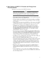
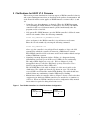
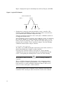
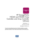
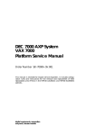
Manual intervention in controller failover—Figure 1 shows a dual-redundant
configuration in which two HSJ40 controllers are attached to a common set
of devices. When one HSJ40 controller in such a configuration fails, manual
intervention is required to bring it back into service.
Figure 1 Two HSJ40 Controllers in a Dual-Redundant Configuration
HSJ40
CONTROLLER
A
CONTROLLER
KILL LINE
HSJ40
CONTROLLER
B
7
Assume that controller A fails in the dual-redundant configuration. If
possible, controller A re-initializes itself. However, surviving controller B
may disable controller A using the kill line if it cannot establish proper
inter-controller synchronization for restarting. If this occurs, the user must
perform the following steps to restore the failed controller to service:
1. At controller B’s HSJ> prompt, enter the following command:
HSJ>RESTART OTHER_CONTROLLER
This command releases the kill line and allows controller A to reboot.
2. Press the OCP reset (//) button on controller A to initiate a reboot of
controller A.
•
Failover time—In a dual-redundant HSJ40 controller configuration, failover
(the assumption of control of drives by the surviving controller when its
partner fails) should normally complete in 30 seconds or less. If there is
no outstanding drive I/O activity at the time of controller failure, failover
should require substantially less than 30 seconds. If drive I/O is in progress
at the time of failure, the surviving HSJ40 controller must reset any SCSI
buses with outstanding I/O. These bus resets can require up to 30 seconds to
complete.
•
NVPM messages—Contact Digital Multivendor Services immediately if any of
the following messages appear; do not use the controller:
All NVPM components initialized to their default settings.
Unknown NVPM Revision Level.
Unknown reformat stage encountered during NVPM Revision Level 1 to 2 reformat.
Controller Characteristics component reformat failed during NVPM
Revision Level 1 to 2 reformat.
Host Access Disabled.
NVPM Controller Characteristics component initialized to default settings.
The following NVPM Manufacturing Failure Information component
elements were initialized to default settings:
(A numeric list of component elements follows this message.)
NVPM Recursive Bugcheck Information component initialized to default settings.
NVPM System Information Page component initialized to default settings.
NVPM Volume Serial Number component initialized to default settings.
•
Informational and error messages—Certain information in the HS Family
of Array Controllers Service Manual Version A01 is incorrect in Chapter 5,
Sections 5.5 and 5.6.
On page 5-12, ignore the paragraph near the top that begins ‘‘This is an
informational message...’’. Ignore the text beginning with the message
‘‘The following NVPM Manufacturing Failure...’’ down to and including the
sentence that begins with ‘‘This information is maintained for power on time
and...’’.
On page 5-13, ignore the CAUTION and the line above it that begins with
‘‘NVPM Volume Serial Number...’’. The two messages and accompanying text
that come after the CAUTION should appear on page 5-12 near the top, just
after the message ‘‘Both HSJ controllers are using SCSI address 7’’. Section
5.6 should be a note which follows these two messages.
8
•
Using DILX to troubleshoot—The Disk Inline Exerciser (DILX) utility tests
logical units which may consist of storage sets or physical devices. Error
reports identify the logical units, not the physical devices. Therefore, if
errors occur while running against a storage set, the storage set should be
reconfigured as individual devices, and then DILX run against the individual
devices.
•
Exiting from the CLI—The HS Family of Array Controllers User’s Guide
contains instructions to exit from the CLI when using a DUP connection, but
does not specify how to do this. Entering EXIT at the HSJ> prompt severs
the DUP connection and effectively exits from the CLI. There is no means (or
reason) to exit from the CLI run from the HSJ40 controller maintenance port.
•
Maintenance port settings—The HSJ40 controller is shipped with its
maintenance port set for 9600 baud and character properties set to 8 data
bits, no parity, and one stop bit.
•
Clarification of SET TRANSPORTABLE or NOTRANSPORTABLE
commands—The following clarifies the CLI Logical Unit SET
TRANSPORTABLE or SET NOTRANSPORTABLE commands in the HS
Family of Array Controllers User’s Guide, Appendix B, and the HS Family of
Array Controllers Service Manual, Appendix B.
In normal operations, the controller makes a small portion of the disk
inaccessible to the host and uses this area to store metadata. This
improves data reliability, error detection, and recovery. This mode is
called nontransportable.
If NOTRANSPORTABLE (the default) is specified, the unit must have
metadata on it to be used by the HSJ40 controller. If the unit has no
metadata and is set NOTRANSPORTABLE, it must be initialized by using
the CLI INITIALIZE command to add the metadata.
If TRANSPORTABLE is specified, the unit must not have metadata on it
to be used by the HSJ40 controller. If the unit has metadata and is set
TRANSPORTABLE, it must be initialized to remove the metadata.
A transportable device is interchangeable with any SCSI interface that does
not utilize the device metadata (for example, a VAX workstation, an SZ200, or
a PC).
A nontransportable device is interchangeable with an HSC K.scsi module or
another HSJ40 subsystem.
Note
Be careful not to confuse the terms transportable and nontransportable
with the commands TRANSPORTABLE and NOTRANSPORTABLE.
Media Format
VAX Workstation
HSC K.scsi
HSJ40
Transportable
Yes
No
Yes
Nontransportable
No
Yes
Yes
9
•
Clarification of port, target, LUN (P T L)—The following are some basic terms
necessary for understanding P T L.
Initiator—A SCSI device that requests an I/O process to be performed by
another SCSI device (a target). This is always the HSJ40 controller.
Port—A uniquely addressable SCSI bus. For example, there are six ports
(numbered 1–6) on the HSJ40 controller.
Target—A SCSI device that performs an operation requested by an initiator.
Target is determined by the device’s address on its SCSI bus. Targets
may be numbered 0–7 (the maximum allowable on a SCSI bus). The HSJ
controller can address targets 0–6 in a single configuration or targets 0–5 in a
dual-redundant configuration.
Logical unit number (LUN)—A physical or virtual peripheral device
addressable through a target. LUNs use their target bus connection to
communicate on the SCSI bus.
Note
LUNs are subunits of a target. In most cases, a target has only one
subunit: LUN 0. Unless specifically indicated, all HSJ controller logical
unit numbers will be LUN 0.
Logical unit (host logical unit)—A physical device or a storage set seen by
the host. Often these logical units are spread across more than one physical
device, especially in RAID implementations. This is not a LUN.
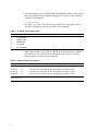
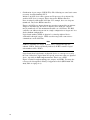
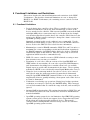
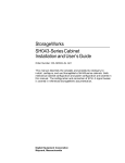
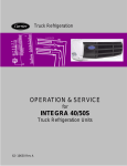
Figure 2 assists in understanding ports, targets, and LUNs. You may also
reference the StorageWorks Family Configuration Guide (EK–BA350–CG.
A02), Table 4–2 (page 4–3).
10
Figure 2 Physical PTL Example
HSJ40 CONTROLLER(s)
PORT
1
PORT
2
PORT
3
PORT
4
PORT
5
PORT
6
INITIATOR(s)
SCSI ADDRESSES 6 AND 7
BA350
SCSI
BUS 6
BA350
BA350
BA350
BA350
5
P
W
R
P
W
R
4
0
2
3
0
0
0
1
0
0
TARGET(s)
0
LUN(s) WITHIN TARGETS
1
2
BA350 STORAGE SHELF
EXAMPLE: THE TARGET AT ADDRESS 0 ON SCSI PORT 6 CONTAINS A DISK DRIVE
WITH 3 HDAs. EACH HDA WITHIN THE TARGET DRIVE IS INDEPENDENTLY
ACCESSIBLE BY USING ITS PORT/TARGET/LUN ADDRESS.
CURRENTLY ALL DRIVES CONTAIN ONLY ONE DEVICE WHICH IS ACCESSED AS LUN 0.
Figure 2 conveys the difference between ports, targets, and LUNs. It shows
a single SCSI bus configuration of target devices in slots 0 through 5, with
all target devices configured on port 6. This dual-redundant controller
configuration also shows the two controllers at SCSI addresses 6 and 7. (In
a vertical configuration the controller nearest the the SCSI cables is SCSI
controller ID 6.)
11
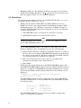
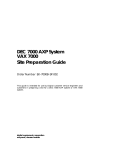
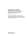
Figure 3 displays the logical relationship between Ports, Targets, and LUNs.
Figure 3 Logical PTL Example
HSJ40 CONTROLLER
PORT 1
·
·
·
TARGET 5
PORT 6
·
LUN
0
•
·
·
TARGET 0
LUN
0
LUN
1
LUN · · ·
2
Clarification of using the warm-swap method to swap a controller—The
following clarifies the HSJ40 controller removal procedure as stated in the
service manual (dual-redundant configuration only).
Using the warm-swap method to remove and replace an HSJ40 controller is
not supported in this release.
In the HS Family of Array Controllers Service Manual, Section 7.2, Removing
the Controller Module in a Dual-Redundant Configuration, step 1, second
bullet, it states the following: ‘‘If the controller has totally failed, press the
program card eject button. If the controller is suspect, enter the following
command to shut down the suspect controller:
CLI>SHUTDOWN OTHER_CONTROLLER
The OCP reset (//) LED should light continuously on the failed controller to
indicate that shutdown is complete on that controller.’’
Currently, both controllers must be shut down in a dual-redundant
configuration because the warm-swap method is not implemented in this
release. Consequently, the missing text for section 7.2 is the following:
Note
All I/O must be halted on the SCSI bus prior to removing an HSJ40
controller.
This is a SCSI bus limitation. Development of the warm-swap method
may be available in a future HSJ40 firmware release. With this release,
both controllers in a dual-redundant configuration must be taken out of
service to remove and replace a failed controller.
Press both program card eject buttons on the controllers, then follow the
remainder of the removal procedure in Section 7.2 of the service manual.
12
6 Functional Limitations and Restrictions
This section describes the functional limitations and restrictions of the HSOF
V1.2 firmware. The first three functional limitations are new or changed for
HSOF V1.1 or HSOF V1.2 firmware; the remaining ones are carried over from
HSOF V1.0B.
6.1 Functional Limitations
•
Device behavior after controller reboot—When a controller reboot occurs in
a multi-host VAXcluster system, the hosts automatically reconnect to the
devices attached to the controller. With current OpenVMS versions (both VAX
and Alpha AXP), these reconnections may be via another host (for example,
served) rather than direct from the host to the controller. This behavior is not
unique to the HSJ40 controller and may be changed in a future version of the
OpenVMS operating system.
Sustained operation in this served condition is not recommended. Use the
VMS Preferred Path utility to restore direct access to the HSJ40 controller’s
devices. Refer to the VMS I/O User’s Guide for more information.
•
Maximum byte count for ERASE commands—HSOF V1.1 and V1.2 enforce a
maximum byte count corresponding to 4,194,303 blocks (about 2 gigabytes)
for ERASE commands. OpenVMS facilities which rely on these commands
automatically adjust to this behavior. Therefore, this is only of concern for
applications which issue these commands directly.
•
DILX—To conserve controller resources, DILX is limited to testing no more
than 18 units at any one time per controller.
•
Translation of event codes—Current versions of the OpenVMS ERF and
UERF utilities do not translate all event codes reported by HSOF firmware,
and documentation describing how to translate them is not yet available.
Digital expects to provide this documentation in the future. Users requiring
translation of HSOF event codes should contact Digital Multivendor Services.
•
Using the device warm-swap method—In order for a device to be removed
and replaced using the warm-swap method, it must first be dismounted
using the OpenVMS DISMOUNT command. Failure to do so may result in
unpredictable behavior, possibly including a host system crash. Other devices
need not be dismounted.
•
Verification errors during copy operations—During large backup operations,
verification errors may be reported by the BACKUP utility. These messages
refer to block numbers that are outside the range of the file, and can safely be
ignored.
•
Striping (RAID 0) functionality—The striping functionality in HSOF V1.1 and
V1.2 is tuned to balance the load across devices and not for maximum data
transfer bandwidth.
•
OpenVMS operating system device size limitation—OpenVMS VAX operating
system versions prior to V6.0 do not support devices larger than 16,777,216
blocks (about 8.5 gigabytes) as file-structured devices. This must be
considered when creating HSJ40 controller storage sets for use with these
OpenVMS operating system versions.
13
•
Minimum chunk size—The minimum chunk size for stripe sets is 16 blocks
(8 KB). The maximum chunk size is 31
blocks, but because this is larger
than any supported disk, it is not a practical limitation.
6.2 Restrictions
The following restrictions are carried over from HSOF V1.0B. There are no new
restrictions unique to HSOF V1.1 or V1.2.
•
HSJ40 controller disks as VAX 7000™ and VAX 10000™ boot devices—
HSOF V1.1 and V1.2 now support manual and automatic booting for VAX
7000/10000 systems. For a disk drive connected to an HSJ40 controller to
be both a VAX 7000/10000 manual and automatic boot device, the following
conditions must be met:
1. VAX 7000/10000 console code must be at version V3.2 or greater.
2. HSOF firmware must be at version V1.0B or greater.
Note
Contact your field service representative if you need to upgrade to V3.2 or
greater VAX 7000/10000 console code.
If your VAX 7000/10000 console code version is earlier than V3.2, you are
limited to manual booting. To manually boot, take the following steps:
1. Ensure that the disk drives attached to an HSJ40 controller are visible to
the boot driver by entering the SHO DEVICE command repeatedly (from
the virtual console) until the disk drives attached to the HSJ40 controller
are reported (usually two repetitions are sufficient).
2. Enter the default boot device string. (Refer to the VAX console
instructions in the VAX console documentation.)
3. Enter BOOT.
•
HSJ40 controller-attached disk drives and VMS AUTOGEN program—The
OpenVMS AUTOGEN.COM file must be edited for HSJ40 controller-attached
disks to be recognized. If AUTOGEN is run without modification in a system
which includes HSJ40 controller-attached disk drives, the following error is
displayed:
"** WARNING ** - unsupported system disk type. Using speed and
size characteristics of an RK07."
The AUTOGEN program does not recognize the device types of the HSJ40
controller’s attached devices. The OpenVMS DCL lexical F$GETDVI returns
the following values:
OpenVMS VAX V6.0
---------------141 - HSX00
142 - HSX01
VAX VMS V5.5-1
OpenVMS VAX V5.5-2
-----------------35 - unknown device
35 - unknown device
The AUTOGEN.COM DCL procedure must be modified to support these
values. See Sections 6.2.1 and 6.2.2.
14
•
HSJ40 controller disk drives may not be used as boot/system disk drives for
the DEC™ 7000/10000 systems. Digital expects to remove this restriction in
the future.
•
CI hardware configuration—All host adapter CI ports in a CI configuration
must have the quiet slot time set to 10. Some older systems may have the
quiet slot time set to 7, which will cause incorrect operation of the CI. This is
a permanent restriction.
•
HSOF V1.1 and V1.2 support the RRD42 CDROM reader with the following
restrictions:
•
One RRD42 per SCSI bus is supported.
•
An RRD42 must be the only device attached to its SCSI bus.
•
VAXcluster Console System (VCS) support—Attaching a VCS through a
DECserver™ to the HSJ40 controller maintenance port is not supported.
•
Transportation of nontransportable devices—The attachment of devices that
have been initialized as nontransportable by an HSJ40 controller or an
HSC95 controller to any other type of controller is not supported. Moving
a nontransportable device to another type of controller or adapter may
cause data loss. Set the media format on devices as transportable using the
following CLI command:
HSJ>SET logical_unit_name TRANSPORTABLE
Refer to Section 5 of these release notes for more information.
Note
Be careful not to confuse the terms transportable and nontransportable
with the commands TRANSPORTABLE and NOTRANSPORTABLE.
•
HSJ40 controller and BA350–SA device shelves—Device SBBs should not
be mounted in slot 6 (ID 6) in a BA350–SA device shelf when an HSJ40
controller to which the shelf is attached is in slot ‘‘A’’ (closest to the SCSI
cables) because an HSJ40 controller mounted in slot ‘‘A’’ uses SCSI ID 6.
6.2.1 VAX VMS V5.5–1 and OpenVMS V5.5–2
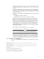
The section of AUTOGEN (from OpenVMS 5.5–2) dealing with devices is listed
below:
$speed_list=" -1, 2, 2, 4, 4, 4, 4, 4, 4, 1, 1,-1,-1, 4,-1, 4,-1,-1, 1, 2"
$speed_list=speed_list + ", 4, 4, 4, 2, 2, 1,-1, 1, 1, 2, 4, 1, 1,-1,-1,-1,-1,-1, 4,
$speed_list=speed_list + ", 1, 1, 1, 4, 4, 1, 4,-1, 4, 4, 4, 4,-1,-1, 4,-1, 4, 4,-1,
$speed_list=speed_list + ", 4, 4,-1,-1, 4, 4, 2,-1,-1,-1, 4,-1, 1,-1, 4, 4, 4, 4, 4,
$speed_list=speed_list + ", 4, 4, 4, 4,-1, 4, 4, 4, 4, 4, 4, 4, 4, 4, 4, 4, 4, 4, 4,
$speed_list=speed_list + ", 4, 4, 4, 4, 4, 4, 4, 4, 4, 4, 4, 4, 4, 4, 4, 4, 4, 4, 4,
$speed_list=speed_list + ", 4, 4, 4, 4, 4, 4, 4"
$diskspeed=-1
$temp = F$GETDVI("sys$sysdevice","DEVTYPE")
$IF (temp .LE. 126) .AND. (temp .GE. 1) THEN diskspeed = F$ELEMENT(temp,",",speed_list)
$disksize = F$GETDVI("sys$sysdevice","MAXBLOCK")
$IF diskspeed .NE. -1 THEN GOTO getdata30
4"
4"
4"
4"
4"
15
The AUTOGEN.COM DCL procedure will select a –1 (unsupported device) from
the speed list. To circumvent this problem perform the following steps:
1. Make a copy of the AUTOGEN.COM DCL file in case restoration of the
original state is required.
2. Edit the AUTOGEN.COM file. Change the 36th element in the speed list
(currently –1) to 4 (the first –1 in the sequence –1, –1, –1, 4, 4 at the end of
line two). This causes HSJ40 controller-attached disk drives to be recognized
as a supported device type.
3. Run the AUTOGEN program.
6.2.2 OpenVMS VAX V6.0
The AUTOGEN.COM DCL procedure does not support device types above 137
although HSX00 and HSX01 are properly defined in the speed list. To circumvent
this problem perform the following steps:
1. Make a copy of the AUTOGEN.COM DCL file in case restoration of the
original state is required.
2. Edit the AUTOGEN.COM file. Change the value 137 in the following
statement to 142.
$IF (temp .LE.
137) .AND. (temp .GE. 1) -
3. Run the AUTOGEN program.
This change will allow AUTOGEN to run successfully against HSJ40 controllerattached disk drives to be used as system disks.
16
7 Recommendations
Digital makes the following recommendations to ensure the most effective use of
HSOF V1.2:
•
The CLUSTER_SIZE qualifier for large devices or storage sets—Digital
recommends that the formula displayed by the OpenVMS operating system
HELP DEVICE INIT/CLUSTER_SIZE command be used to determine the
proper OpenVMS file system cluster size. Using too small a file system
cluster size may prevent some of the device or storage set capacity from being
accessed; too large a cluster size usually wastes storage capacity by allocating
large blocks of storage for small files.
•
Shadow set operation—In OpenVMS VAX operating system versions earlier
than V6.0, timed-out I/O requests to shadow set members may lead to
member disks attached to HSJ40 controllers being dropped from shadow
sets. In some cases, this may lead to host crashes. To avoid this possibility,
Digital strongly recommends changing the value of the SYSGEN parameter
SHADOW_MBR_TMO to at least 120 (seconds) for systems running operating
system versions earlier than V6.0. Version 6.0 of OpenVMS avoids this
problem by retrying timed-out operations to shadow set members several
times.
•
PAPOLLINTERVAL and PANUMPOLL parameters—Digital recommends
that the SYSGEN parameters PAPOLLINTERVAL and PANUMPOLL be set
such that all nodes in the cluster are polled within 30 seconds or less. This
ensures proper operation of the CI in the event of a controller reboot. Failure
to set this value may result in MSCP command timeouts. The default values
are set to poll 16 node clusters every 5 seconds and 32 node clusters every 10
seconds.
•
OpenVMS operating system device size limitation (in HSOF V1.1 or later
versions)—If previous recommendations regarding device size limitations
were not followed and devices larger than 4 gigabytes were created, HSOF
V1.1 or later versions will eliminate possible problems that may result.
However, a reboot of the VMScluster is strongly recommended to clear
controller parameters maintained by the operating system from the prior
HSOF version.
•
Concurrent operation of exercisers—The Disk Inline Exerciser utility (DILX)
and the Tape Inline Exerciser (TILX) utility may run concurrently with one
initiated from the HSJ40 maintenance terminal port and the other from a
DUP connection. Digital recommends, however, that TILX not be run while
normal I/O operations are in progress, as it will degrade system performance
due to the heavy load it imposes on the controller.
•
DILX concurrent operation—While DILX functions correctly when run
concurrently with normal controller operation of drives other than those
being exercised, Digital recommends that it not be run during periods when
application I/O performance is important because it generates a heavy I/O
load.
•
Device warm-swap method—Device that are removed using the warmswap method should normally be replaced with devices of the same type.
Otherwise, failure of system startup procedures such as the establishment of
stripesets could result.
17
•
18
Preferred Path utility—Use the OpenVMS Preferred Path utility to balance
units between controllers for better performance in a dual-redundant
configuration. Refer to the VMS I/O User’s Guide for more information.
8 HSJ40 Controller Performance
Digital has measured HSJ40 controller performance with HSOF V1.2 firmware.
The following results were observed:
Performance Characteristic
Measured Value for HSOF V1.2
I/O requests per second completed
Up to 1,100
MBytes/second of data written
Up to 4.0
MBytes/second of data read
Up to 2.6
These results are extremely dependent on the profile of the I/O workload. The
maximum I/O request rate, for example, has been measured with very short
requests (512 bytes) with high locality of reference in order to minimize the
effect of mechanical disk performance. Maximum data transfer capacity has been
measured by writing very large sequential streams of data. In both cases, the
benchmarks were constructed to exercise the HSJ40 controller and HSOF to the
maximum and not to represent realistic application workloads.
Measurements of internal controller resource utilization suggest strongly that
substantial further performance optimization of HSOF is possible; a greater
I/O request throughput might be achieved with sufficient tuning. Digital
fully expects, but does not guarantee, that future versions of HSOF will offer
incremental I/O performance improvements.
Performance of HSOF’s RAID Level 0 (disk striping) functionality has not been
measured for this HSOF version. Digital expects to provide such data in the
future.
19
9 HSOF Firmware V1.2 Installation
Use the procedures described in this section to install the HSOF V1.2 firmware,
supplied in this kit. The procedure for upgrading your firmware to V1.2 will
typically take less than five minutes to accomplish.
Important Notice
If the CI node number but not the SCS node name is changed, a complete
VMScluster system reboot must be performed before the HSJ40 controller
and its attached devices will be recognized. It is not necessary to change
the CI node number or the SCS node name when upgrading from HSOF
Version T047 (or later) to V1.2 of the firmware.
9.1 Upgrading Firmware in Nonredundant HSJ40 Configurations
The HSOF upgrade to V1.2 will cause a brief (30-45 second) interruption in
service to attached drives. The OpenVMS operating system should automatically
recover from this outage within a few seconds after the new firmware becomes
operational and restore service to users.
Use the following procedure to upgrade the firmware in a nonredundant HSJ40
controller:
1. Locate the controller to be shut down.
2. Remove the EMI shield (if one is installed).
3. Press the program card eject button to eject the program card from the
controller.
4. Remove the program card.
5. While holding in the OCP reset (//) button, insert the new program card,
pressing the card in until the eject button extends outward almost even with
the card, then release the reset (//) button.
6. Replace the EMI shield over the card.
The controller restarts, leading to normal operations with the host system(s) as
described in the HS Family of Array Controllers User’s Guide.
9.2 Upgrading Firmware in Dual-Redundant HSJ40 Configurations
In dual-redundant configurations, you may upgrade the firmware of the
controllers simultaneously or in sequence. A simultaneous upgrade requires a
momentary service outage, but preserves the assignment of drives to controllers.
A sequential upgrade does not result in service outage, but generally requires
that drive assignments to controllers be adjusted after completing the upgrade.
This occurs because as you take each controller momentarily out of service to
exchange firmware, its drives fail over to the partner controller, disturbing the
balance of drives.
20
9.2.1 Simultaneous Upgrade
The simultaneous upgrade method requires that both controllers be momentarily
shut down at the same time, causing a brief (30-45 second) interruption in service
to attached drives. The OpenVMS operating system should automatically recover
from this outage within a few seconds after the new firmware becomes operational
and restore service to users.
Note
A simultaneous upgrade maintains the pre-upgrade drive-to-controller
assignments.
A simultaneous upgrade is valid for upgrades from any previous HSOF
version to V1.2.
Use the following procedure to perform a simultaneous firmware upgrade in a
dual-redundant configuration:
1. Press the program card eject buttons on both controllers simultaneously and
remove both program cards.
2. Press and hold the OCP reset (//) buttons on both controllers while inserting
new program cards. Be sure the eject buttons extend outward almost even
with the cards.
3. Release the reset (//) buttons.
Both controllers will restart, leading to normal operations with the host system(s)
as described in the HS Family of Array Controllers User’s Guide.
The two controllers will re-initialize concurrently and will synchronize with each
other. The timing of this procedure is not critical, except that the program cards
should be removed and inserted at approximately the same time (within an
interval of a few seconds).
After installation, use of the OpenVMS operating system Preferred Path utility
may be required to restore the desired load balance among the drives attached to
the two controllers.
9.2.2 Sequential Upgrade
This sequential upgrade method keeps at least one controller in operation at all
times for continuous service to drives. After the upgrade, however, the system
manager must generally use the OpenVMS Preferred Path utility to restore the
desired attachments of drives to the two controllers.
Note
A sequential upgrade disrupts pre-upgrade drive-to-controller
assignments
A sequential upgrade is valid only for upgrades from HSOF V1.1 to V1.2.
21
Use the following procedure to perform a sequential firmware upgrade in a dualredundant configuration (the two controllers are arbitrarily designated Controller
A and Controller B.):
1. Enter the SHUTDOWN THIS_CONTROLLER command at the HSJ> prompt
for Controller A. This causes (live) Controller B to assume control of the
shutdown Controller A’s drives.
2. Remove the EMI shield (if attached) from the shutdown Controller A.
3. Press shutdown Controller A’s eject button, and remove its program card.
4. Press and hold Controller A’s OCP reset (//) button while pushing in the new
program card. Be sure the eject button extends outward almost even with the
card.
5. Release Controller A’s reset (//) button.
6. Enter the RESTART OTHER_CONTROLLER command at Controller B’s
HSJ> prompt.
7. Press the OCP reset (//) button on shutdown Controller A. Controller A now
re-initializes and reestablishes communication with Controller B and the host.
8. Repeat the procedure, interchanging Controller A and Controller B. This time
Controller A, upgraded to HSOF V1.2 first, will serve all devices to the host.
After you complete the upgrade, use the OpenVMS operating system Preferred
Path utility as required to restore the desired controller-to-drive assignments.
22