1
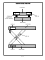
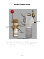
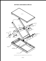
Installation, Operation and Maintenance
Manual for the Following Equipment:
ALL AIR TABLES
MODELS, AT, ATT, ATR, ATI
In any correspondence with your distributor you will need the following information:
Model Number______________________ Serial Number_____________________________
Installation location: __________________________________
__________________________________
__________________________________
CAUTION:
Proper familiarization with this manual is essential for safe operation of the unit.
Carefully read the operating and maintenance instructions before operating the lift.
Distributor Information: ______________________________
_______________________________
_______________________________
Advance Lifts, Inc.
701 S. Kirk Road
St. Charles, IL 60174-3428
Toll Free 1-800-843-3625
Sales Fax 1-630-584-9405
Parts and Service Fax 1-630-584-6837
E-mail: [email protected]
*Advance Lifts, Inc. furnishes one manual with each unit. Additional manuals are available for
$25.00 each.
P 1-1
SECTION 2. INDEX & INTRODUCTION
Identification Sheet………………………………………………………….
Index & Introduction…………………………………………………………
*Responsibilities Of Owners & Users….………………..………………..
*Installation Instructions……………………………..……………………..
*Operation Instructions………………………………………………………
*Maintenance Instructions……………………………………………….. …
*Safety Bar Placement
Warning Label Specifications & Locations ……………………………….
Pneumatic Details……………………………………………………………..
General pneumatic information
Pneumatic schematics
Pneumatic component lists
Mechanical Details…………………………………………………………..
Troubleshooting Hints……………………………………………………….
Warranty………………………………………………………………………
Attachments: Parts List……………………………………………………..
Optional Accessory Information (Only included when appropriate)…..
Section 1
Section 2
Section 3
Section 4
Section 5
Section 6
Section 7
Section 8
Section 9
Section 10
Section 11
Section 12
Section 13
*Mandatory reading before attempting installation.
INTRODUCTION
Congratulations, the equipment that you have purchased is of the highest quality
available. Your Advance Lift will provide you with many years of trouble free service in
return for the minimal maintenance described in this manual.
Please be sure that no individual is allowed to operate the lift until they have been fully
familiarized with the operating instructions in this manual. Also, insure that at least one
person at the lift site is familiar with the maintenance section of this manual and is
assigned responsibility for doing the maintenance on a regular basis.
Please note that the lift has a metal nameplate attached to it that contains information
such as the model number, capacities, and serial number. Do not remove the
nameplate. Be sure that no operator ever exceeds the capacities shown on the
nameplate or they may injure personnel or cause damage to the lift.
Also, be sure to have the serial number of the lift handy if you have to call your
distributor. That number identifies your specific lift and will allow your distributors
personnel to give you the most thorough and timely assistance possible.
This manual is under constant review and we would appreciate any constructive
suggestions that may enhance its usefulness. Please send your suggestions to
Advance lifts, Inc. Attn: Customer Service Department.
Thank you for purchasing our product.
P 2-1
SECTION 3. RESPONSIBILITIES OF OWNERS & USERS
Inspection and Maintenance: The lift shall be inspected and maintained in proper
working order in accordance with this manual and safe operating practices.
Removal from Service: Any lift not in safe operating condition shall be removed from
service until it is repaired to the original manufacturer’s standards.
Repairs: Authorized personnel in conformance with the manufacturer’s instructions
shall make all repairs.
Operators: Only trained and authorized personnel shall be permitted to operate the lift.
They must understand to be alert to safety hazards during all operations.
Before Operation: Before using the lift, the operator shall have:
1. Read and understood the manufacturer’s operating instructions and safety rules, or
been trained by a qualified person.
2. Inspected the lift for proper operation and condition. Any suspect item shall be
carefully examined and a determination made by a qualified person as to whether it
constitutes a safety hazard. All unsafe items shall be corrected before further use of
the lift.
During Operations: The lift shall be used only in accordance with its intended use and
within the manufacturer’s limitations and safety rules:
1. Do not overload the lift.
2. Insure that all safety devices are operational and in place.
3. Insure that all personnel near the operating lift understand to stand back so that no
body parts can be pinched by the mechanism or platform and any items that may fall
off the lift will not strike them.
Modifications Or Alterations: Modifications or alteration of industrial scissors lifts shall
be made in conformance with all applicable provisions of scissors lift manufacturer’s
proposed ANSI standards and shall be at least as safe as the equipment was before
modification. These changes shall also satisfy recommendations of the original
equipment manufacturer for the particular application of the lift.
P 3-1
SECTION 4. INSTALLATION INSTRUCTIONS
Floor mounted units with baseframes, lift & turn, lift & tilt and tilt units:
1. Move the lift to the usage area; insuring the floor is clean and level. If slings are
used, encircle the entire lift, not just the platform.
Caution! Before securing the unit to the floor, shim or grout the entire baseframe
assembly. Continuous baseframe support is essential for proper installation.
2. Connect the air supply line to the control valve. Recommended air pressure is 70
PSI @ 20 SCFM. Maximum air pressure is 100 PSI for lifting rated load.
3. Using the control valve, fully raise the lift and insert the maintenance bars. CAUTION!
See page (P 6-3) for complete instructions on using the maintenance bars.
4. Lag the unit in place using ½” x 5”, “Rawl-Studs” or wedge anchors in the holes
provided.
5. Clean any debris remaining from installation. Remove maintenance bars and lower
the unit.
6. Instruct user(s) in the proper operation of the lift, safety precautions, and equipment
capacity. Supply maintenance personnel with this service manual.
Pit mounted units:
1. Check all pit dimensions for accuracy.
2. Attach a temporary air line through the pit conduit to the lift.
3. Using slings, encircle the entire lift, not just the platform and lower the lift into the pit,
centering it for 1” minimum clearance on all sides to the pit wall.
4. Raise the lift with the control valve and remove the slings. Run the unit up and down
several times to insure proper clearances on pit walls.
5. Fully raise the unit and insert maintenance bars, lower unit onto the bars and
discharge air until air pressure is relieved from the system. CAUTION! See page (P
6-3) for complete instructions for proper maintenance bar instruction.
6. Level and center the lift by shimming and grouting the entire baseframe, not just the
corners. Lag the unit in place using ½” x 5”, “Rawl-Studs” or wedge anchors in the
holes provided.
Caution! Continuous baseframe support is essential for proper installation
7. Follow the instructions outlined in paragraphs 5 and 6 under “Floor mounted
installation”. To complete the installation.
P 4-1
SECTION 5. OPERATING INSTRUCTIONS
Pneumatic scissors lifts have an excellent safety record overall, but as with all moving
equipment, they can be dangerous. Operators must use common sense and take
responsibility for the safety of everyone near the lift. They must use the safety devices
provided and be careful not to surprise anyone in the area with the movement of the lift.
Pre-operational checks:
1. Check all air connections to be sure that they are completed properly and are
operational.
2. The air supply shall be regulated at 70 PSI; it shall also be dry.
3. Check for obstructions or debris that may interfere with the safe operations of the lift.
4. Be sure that all personnel in the area are a safe distance away from the lift and
aware that you are about to operate it.
5. If there are any optional safety devices such as limit switches, check them for proper
operation.
Test operate the equipment:
1. Station yourself so that you will always see the equipment when it is in operation.
Never operate the equipment blind!
2. Raise the equipment and note that the control is a constant pressure, “dead-man”
type. The control knob shall spring to the neutral position when pressure is released,
if not, the control shall be rebuilt or replaced.
3. Cycle the equipment several times to be sure that it is operating smoothly with no
jerking or sudden movement. If the operation is not smooth after several cycles,
contact your maintenance personnel to have the air plumbing checked. Any
evidence of binding or scraping in the operation shall cause you to immediately stop
using the lift and contact the factory.
4. Check all safety devices for proper operation.
5. If you elect to test load the equipment be sure that you do not exceed the capacities
shown on the nameplate. Overloading may cause structural stresses that may not
show up for some time, but will diminish the life and capacity of the unit. If you have
any questions about testing the unit, call our customer service department at 1-800843-3625.
Daily operation:
1. All personnel shall be required to read the entire operating instruction section of this
manual prior to operating the lift.
2. Operators must know the capacity of the unit and be aware of any loads that may
exceed the capacity.
3. WARNING! Operators must be alert to personnel in the vicinity of the lift. Avoid any
surprises to these personnel in regard to movement of or the position of the lift.
Never operate unit if you cannot see it and the personnel around it.
P 5-1
SECTION 5. (CONTINUED) OPERATING INSTRUCTIONS
Daily operation (continued):
4. On the first use of the lift each day, the operator shall check to see that the lift is
functioning properly and smoothly. All safety devices shall be in place and operating
correctly.
5. If the unit has a traveling air line, the operator must insure that it is kept away from
the lift as it raises and lowers.
6. The center of the load shall be centered on the platform before raising or lowering
the lift as this will help insure even wear on all moving parts
General Compressed Air Information Notes:
1. PSI and SCFM will affect the speed and capacity of an air spring actuated lift. An
increase in PSI will increase the capacity of the lift, as a drop in PSI will reduce the
lift capacity.
2. SCFM and load weight will primarily affect the speed in which the table rises. While
load weight will have the greatest effect on the lowering speed.
3. Advance Lifts air spring lifts are designed to operate at 70 PSI.
SECTION 6. MAINTENANCE INSTRUCTIONS
1. Always remember that machinery with large moving parts can seriously injure you.
2. Read and understand this manual before attempting any service work.
3. WARNING! Always use the safety bars or safety leg when working on the unit in the
elevated position or reaching under the platform. (See photos 6-1 and 6-2, at the
end of this section for proper positioning and engagement of the safety bars).
4. When using the safety bars, adhere to the following rules:
A. The unit must be unloaded.
B. Be sure the safety bars are properly engaged.
C. Hold the down pedal or pushbutton an extra 10 seconds when lowering onto the
safety bars to be sure that all the weight of the lift is on the bars.
D. Disconnect and tag the electricity to the unit to prevent accidental movement of
the lift by other personnel.
E. Spend as little time as possible under the lift.
5. Only use replacement parts recommended by the manufacturer.
6. Do not let the equipment stay in disrepair, fix small problems before they become big
problems. A unit in disrepair can become a severe hazard if left unattended.
7. Inspect the equipment on a regular schedule, preferably monthly.
P 6-1
SECTION 6. (CONTINUED) MAINTENANCE INSTRUCTIONS
8. Never work on the pneumatic systems unless the unit is fully lowered or properly
sitting on the safety support or wheel block.
9. Never apply a load to the equipment until the baseframe is continuously supported.
10. WARNING! Never expect to hold the leg assemblies open by simply lifting one end
of a platform.
A. The roller end of most lifts is not “gibbed” or captured in any way, so lifting on the
roller end will simply tilt the platform.
B. Even if you raise the clevis end of the platform, if the base frame is not firmly
lagged to the ground or held down by some other means, the legs will come up
with the platform in an unpredictable manner and could cause personal injury.
C. The only safe way to hold a lift’s legs open other than the factory designed safety
support, is to block between the clevis end of the platform and the baseframe.
Routine Maintenance: (All lifts)
Weekly: Once a week or after repetitive operation, the unit shall be raise to its full
height. The air spring and supply hose shall be examined for signs of wear.
Monthly:
WARNING! Be sure a maintenance safety leg or safety bars are properly engaged
before performing maintenance checks 2 through 6 or reaching beneath a raised lift.
(See instructions 3, 4 and 10 above).
1. Clean all debris from the vicinity of floor and pit mounted units in order to avoid
interference with the lift mechanism or rollers.
2. Check for presence and proper seating of all snap rings and clips on all axles and
rollers.
3. Check rollers, pins and bushings for any signs of wear such as flat spots, missing
fasteners, or dislodged bearing material.
4. Check the pneumatic fittings for cracks or leaks.
5. Check hoses for abrasions or other abuse and check for snug connections.
6. Operate the unit and check for any abnormal noise or vibrations.
7. Check all safety devices on the unit such as the condition of the pleated bellows or
smooth operation of a limit switch.
P 6-2
SECTION 6. (CONTINUED) MAINTENANCE INSTRUCTIONS
SAFETY MAINTENANCE BAR INSTRUCTIONS
WARNING! Always use the safety bars for any service or maintenance. Never go or
reach under the lift unless both safety bars are securely in place and the power to the
unit has been disconnected to prevent others from operating the lift. Never use the
safety bars with a load on the platform.
CAUTION! Never use the lift unless the safety bars are properly stored or damage may
occur to the equipment.
1. Remove the safety bars from their storage positions by loosening the wing bolts.
2. Raise the lift to full travel, and place a safety bar in front of each roller wheel on the
scissors leg. Make sure the safety bar angle captures the baseframe angle (see
photos numbered 6-1 and 6-2). Caution! Do not tighten the wing bolt.
3. Once both safety bars are in place, slowly lower the lift until the roller wheel is
engaged with the safety bars and the safety bars rest against the end of the
baseframe. Visually inspect both safety bars to insure they are secure.
4. To disengage the safety bars raise the lift to move the roller wheels off the safety
bars and make sure lift operates correctly. If assistance is required in removal of the
safety bar, lightly tap with a hammer to brake it loose. Store the safety bars in their
original position and tighten the wing bolt.
Store the safety maintenance bar in position shown below. Failure to do so would allow
the moving leg to impact the maintenance bar when the list is fully lowered. (See the
photographs, 6-1 and 6-2).
Maintenance Bar in
use
(Photo 6-1)
Maintenance Bars
in Stored Position
(Photo 6-2)
P 6-3
SECTION 7. WARNING LABEL SPECIFICATIONS & LOCATIONS
WARNING LABEL LOCATIONS & SPECIFICATIONS
The warning and informational labels normally attached to P Series, LT and LTD lifts,
are shown below and their proper mounting locations are shown on page 7-2.
Descriptions of the labels are as follows:
Label 1: This is simply a promotional label identifying the unit as Advance Lifts unit.
Label 2: This is the formal nameplate and it shall never be removed from the unit. The
serial number on this nameplate is critical in identifying the specific unit for correct parts
and service information. This plate also informs all readers of the proper capacity limits
of the unit.
Label 3: This is an important “Danger” label that warns users of the three greatest
hazards.
Label 4: This is a “Warning” label to not ride on the unit.
Label 5: This is a “Danger” label reinforcing the need to use maintenance safety legs.
P 7-1
WARNING LABEL LOCATIONS
PLATFORM
FORMAL
NAMEPLATE
(DO NOT REMOVE)
LABEL #2
BASEFRAME
LABEL #2
PLATFORM
LABEL #4
LABEL #5
BASEFRAME
P 7-2
SECTION 8. PNEUMATIC DETAILS
FROM
COMPRESSOR
FLOW VALVE
BLEED
VALVE
SUPPLY AIR
(TO LIFT)
SUPPLY AIR
(TO LIFT)
AIR EXHAUST
FROM
COMPRESSOR
TYPICAL AIR CONTROLLERS
The hand valve (left) is a typical two-position air valve. Constant pressure must be
applied to the control knob for the lift to operate. The foot valve (right) is of a similar
design and constant pressure on the pedal is required for lift operation. The foot
valve is supplied with a protective cover that has been omitted for clarity.
P 8-1
SECTION 9. MECHANICAL DETAILS
Platform
Platform Pins
Retaining
Clip
Inner Leg
Wheel Pin
Bearing
Outer Leg
Spacer
Wheel
Retaining
Clip
Bearing
Baseframe pin
Wear Pad
Retaining
Clip
Retaining
Clip
Wheel
Bearing
Retaining Clip
Spacer
Main Axle Pin
Bearing
Wheel Pin
Retaining
Clip
Baseframe
Clevis
Air Spring
Mounting Plate
Baseframe
(Drawing for reference only, Air Spring Removed, Not all options shown)
P 9-1
SECTION 10. TROUBLESHOOTING HINTS
Warning! Only qualified service personnel shall be allowed to perform service work on
pneumatic lifts. The service person shall be familiar with this manual before attempting
any service on the lift.
Warning! No work shall be performed beneath a raised lift platform unless the safety
leg or maintenance blocks are installed in accordance with Section 6 of this manual
UNIT WILL NOT LIFT
1. Reduce load to rated capacity.
2. A small amount of debris may be stuck in the control valve. Disassemble the air
valve and clean.
3. Confirm correct air pressure supply; refer to Section 5 for correct operating pressure.
4. Check air lines for kinks or damage.
5. Inspect lift for physical damages that may be causing binding and restricting travel.
UNIT WILL NOT LOWER
Danger! If a lift fails to lower when the valve is actuated yet air is being relieved from the
valve great caution must be exercised. Air spring tables are slower to react than
hydraulic lifts and mechanical binding or debris may be restricting the lifts travel. If the
binding or debris is removed before the table is raised, the table may drop suddenly.
1. An object or debris may be blocking the rollers from moving. Caution! Do not attempt
to remove an obstruction without first raising the unit to full height and inserting the
maintenance blocks, See page 6-3 for instructions.
2. The air control valve may be malfunctioning, raise the unit and install the
maintenance blocks, then disassemble and clean the valve components.
P 10-1
ADVANCE LIFTS INC. WARRANTY
For a period of one year from date of shipment from the Company’s plant, the
Company agrees to replace or repair, free of charge, any defective parts,
material or workmanship on new equipment. This shall include electrical and
hydraulic components.
For a period of ten years or 125,000 cycles (whichever occurs first) from date of
shipment from Company’s plant, the Company agrees to replace or repair any
defective structure.
Company authorization must be obtained prior to the commencement of any
work. The Company reserves the right of choice between effecting repairs in the
field or paying all freight charges and effecting the repairs at the Company’s
plant. The Company further reserves the right of final determination in all
warranty considerations. Evidence of overloading, abuse or field modification of
units without Company approval shall void this warranty. No contingent liabilities
will be accepted.
Damage incurred in transport is the responsibility of the carrier and is not
covered by this warranty. Any damage detected upon receipt of equipment
should be immediately reported to the carrier. If you need assistance filing your
claim, please contact Advance Lifts.
W-04-07
ADVANCE LIFTS “AT” SERIES PARTS LIST
ROLLER WHEEL ASSEMBLY
ROLLER WHEEL PIN (UPPER)
ROLLER WHEEL PIN (LOWER)
ROLLER PIN BEARING (ALL)
ROLLER WHEEL SPACER (ALL)
ROLLER WHEEL RETAINING CLIP
ROLLER WHEEL WEAR PAD
P-023-878
P-A-10346
P-A-9993
P-000-363
P-001-483
P-001-876
P-A-9555
MAIN AXLE PIN
MAIN AXLE RETAINING CLIP
MAIN AXLE BEARING
P-A-9992
P-001-876
P-000-363
PLATFORM/BASEFRAME PINS
PLATFORM/BASEFRAME CLIP
P-A-9992
P-001-876
HAND VALVE
BLEED VALVE
FLOW VALVE
AIR SPRING
RELIEF VALVE
P-001-318
P-001-501
P-001-339
P-001-881
P-001-308
REPLACEMENT SAFETY BAR
REPLACEMENT DECAL KIT
REPLACEMENT MANUAL
P-A-6275
P-004-138
P-004-539
ADVANCE LIFTS “ATT” SERIES PARTS LIST
LIFT TABLE ROLLER WHEELS
P-006-223
ROLLER WHEEL RETAINING CLIP
P-001-876
ROLLER WHEEL SPACER
P-001-845
LEG TO PLATFORM PIN
P-A-0234
LEG TO BASE FRAME PIN
P-A-0235
PIN RETAINING CLIPS
P-001-876
TURN TABLE CAM FOLLOWERS
P-003-892
CAM FOLLOWER MOUNTING BOLT
P-004-067
MOUNTING BOLT LOCK WASHER
P-004-066
MOUNTING BOLT NUT
P-004-065
FOOT VALVE (AIR)
P-001-316
BLEED VALVE
P-001-501
FLOW VALVE
P-001-339
RELIEF VALVE
P-001-308
AIR SPRING
P-001-868
ATR'S (AIR POWERED WITH TURN MANUAL)
OUTER WHEEL PIN 1" x 1.97"
INNER WHEEL PIN 1" x 2.344"
BASE/PLAT PIN 1" x 2 1/4"
WHEEL ASSEMBLY
CAM FOLLOWER (WHEELS)
NUT
LOCK WASHER
BOLT
90 DEGREE DETENT ASSEMBLY
P-A-9993
P-A-10346
P-A-9992
P-023-878
P-003-892
P-004-065
P-004-066
P-004-067
P-004-069
AIR BAG 2 HOLE AIR BAG 4 HOLEHAND VALVE ASSEMBLY
FOOT VALVE ASSEMBLY
P-001-881
P-001-868
P-004-540
P-004-535
ATI'S (AIR OPERATED TILTER)
PLATFORM TO BASE PIN
SHOCK ABSORBERS
SHOCK ABSORBER KIT
P-A-0234
P-027-912
P-027-905
052406