1
EPSON TERMINAL PRINTER
EPL-5000/5200/5200+
#mLm. 1000 I15OO
SERVICE MANUAL
EPSON
4001962
PRECAUTIONS
Precautionary notations throughout the text are categorized relative to 1) personal injury and 2)
damage to equipment.
DANGER Signals a prwaution which, if ignorwl, could result in serious or fatal personal injury.
Great caution should be exercised in performing procedures preceded by DANGER
Headings.
WAHV/NG Signals a precaution which, if ignored, could result in damage to equipment.
The precautionary measures itemized below should always be observed when performing repair/
maintenance procedures.
(. .
DANGER
..
\
)
1.
ALWAYS DISCONNECT THE PRODUCT FROM BOTH THE POWER SOURCE AND
PERIPHERAL DEVICES PERFORMING ANY MAINTENANCE OR REPAIR PROCEDURE.
?-.
NO WORK SHOULD BE PERFORMED ON THE UNIT BY PERSONS UNFAMILIAR WITH
BASIC SAFETY MEASURES AS DICTATED FOR ALL ELECTRONICS TECHNICIANS IN
THEIR LINE OF WORK.
3.
WHEN PERFORMING TESTING AS DICTATED WITHIN THIS MANUAL, DO NOT
CONNECT THE UNIT TO A POWER SOURCE UNTIL INSTRUCTED TO DO SO. WHEN
THE POWER SUPPLY CABLE MUST BE CONNECTED, USE EXTREME CAUTION IN
WORKING ON POWER SUPPLY AND OTHER ELECTRONIC COMPONENTS.
WARNING
.
(
:.
REPAIRS ON EPSON PRODUCT SHOULD BE PERFORMED ONLY BY AN EPSON
CERTIFIED REPAIR TECHNICIAN.
MAKE CERTAIN THAT THE SOURCE VOLTAGE IS THE SAME AS THE RATED VOLTAGE, LISTED ON THE SERIAL NUMBER/RATING PLATE. IF THE EPSON PRODUCT
HAS A PRIMARY AC RATING DIFFERENT FROM AVAILABLE POWER SOURCE, DO
NOT CONNECT IT TO THE POWER SOURCE.
3.
ALWAYS VERIFY THAT THE EPSON PRODUCT HAS BEEN DISCONNECTED FROM
THE POWER SOURCE BEFORE REMOVING OR REPLACING PRINTED CIRCUIT
BOARDS AND/OR INDIVIDUAL CHIPS.
4.
IN ORDER TO PROTECT SENSITIVE MICROPROCESSORS AND CIRCUITRY, USE
STATIC DISCHARGE EQUIPMENT, SUCH AS ANTI-STATIC WRIST STRAPS, WHEN
ACCESSING INTERNAL COMPONENTS.
5.
REPLACE MALFUNCTIONING COMPONENTS ONLY WITH THOSE COMPONENTS
BY THE MANUFACTURE; INTRODUCTION OF SECONBSOURCE ICS OR OTHER
NONAPPROVED COMPONENTS MAY DAMAGE THE PRODUCT AND VOID ANY
APPLICABLE EPSON WARRANTY.
c)
- ii -
SAFETY INFORMATION
This printer is a page printer which operates by means of a laser. There is no possibility of danger from
the laser, provided the printer is operated according to the instructions in this manual provided.
Since radiation emitted by the laser is completely coti-ined within protective housings, the laser beam
camot escape from the machine during any phase of user operation.
For United States Users:
[Laser Safety]
This printer is certified as a Class 1 Laser product under the U.S. Department of Health
and Human Services (DHHS) Radiation Performance Standard according to the Radiation Control for Health and Safety Act of 1968. This means that the printer does not
produce hazardous laser radiation.
[CDRH Regulations]
The Center for Devices and Radiological Health (CDRH) of the U.S. Food and Drug
Administration implemented regulations for laser products on August 2,1976. Compliance is mandatory for products marketed in the United States. The label shown below
indicates compliance with the CDRH regulations and must be attached to laser products
marketed in the United States.
‘WARNING: Use of controls, adjustments or performance of procedures other
than those specified in this manual may result in hazardous radiation exposure.
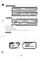
[Internal Laser Radiation]
Maximum Radiation Power:
Wave Length:
5.7 x 10⁴ (w)
780 nm
This is a Class IIIb Laser Diode Assay that has an invisible laser beam. The print head
unit is NOT A FIELD SERVICE ITEM. Therefore, the print head unit should not be
opened under any circumstances.
For Other Countries Users;
wARNING: Use of controls, adjustments or performance of procedures other
than those specified in this manual maY result in hazardous radiation exposurel
?his is a semiconductor laser. The maximum power of the laser diode is 5.7 x
10-4 W and the wavelen @h is 780 nm.
For Denmark Users;
ADVARSEL
Usynlig laserstrMng ved i%bning, dir sikkerhedsafbrydere er ude af funktion.
Undg~ udsaXtelse for striWng.
IKlasse 1 laser produkt der opfy lder IEC825 sikkerheds kravene.
...
- Ill -
I
For Finland, Sweden Users;
I
Laitteen kayttaminen muulla k u i n tiissa kaytttiohjeessa mainitulla tavall
aattaa altistaa kiiyttajan turvallisuusluokan 1 ylittavalle nakymattomiill 2
WMNING
Om apparaten anvirinds pa annat salt an i dema bruksanvisning specificerats,
kan anvandaren utsattas for osynlig laserstr~lning, som tiverskrider griinser
For Norway Users;
ADVARSEL
Dersom apparatet brukes ptl annen rrdte em spesifisert i deme bruksanvisnmg, kan brukeren utsettes for unsynlig laserstri%ling som overskrider grensen
@ laser klasse 1.
1
ette er en hafvleder laser. Maksimal effeckt til laserdiode er 5.7x 10”4 W
algelengde er 780 nm.
Laser Safety Labels
[Label on rear printer case]
A laser safety labels is attached on the outside of the printer shown below.
For United State
(-”. :
..,
P
r
r
‘~‘‘‘
.
.
-
.-.
p
\
El,
~;/
\
mk laser pomct rxnfcms
to the
applicable requirement of 21 CFR
Chapter 1, Sued’mpler J.
SEIKO EPSON CORP.
Hirooka OtSkx
80 Hirooka Shiojiri-shi, Nagarwken.
JAPAN
MANUFACTURED:
)
+,
(3
- iv -
For Europe
.
[Label inside printer]
The following laser safety label will be attached inside the printer as shown below.
-v-
PREFACE
This manual describes functions, theory of electrical and mechanical operations, maintenance, and repair
of EPL-5000 /5200 and Action Laser 1000/1500.
The instructions and procedures included herein are intended for the experience repair technician, and
attention should be given to the precautions on the preceding page. The chapters are organized as
follows:
CHAPTER 1. GENERAL DESCRIPTION
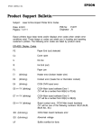
Provides a general product overview, lists specifications, and illustrates the main components of the printer.
CHAPTER 2. OPERATING PRINCIPLES
Describes the theory of printer operation.
CHAPTER 3. DISASSEMBLY AND ASSEMBLY
Includes a step-by-step guide for product disassembly and assembly.
CHAPTER 4. ADJUSTMENTS
Includes a step-by-step guide for adjustment.
CHAPTER 5. TROUBLESHOOTING
Provides Epson-approved techniques for adjustment.
CHAPTER 6. MAINTENANCE
Describes preventive maintenance techniques and lists lubricants and adhesives required to service the equipment.
APPENDIX
Describes connector pin assignments, circuit diagrams, circuit board component layout and exploded diagram.
The contents of this manual are subject to change without notice.
- vi -
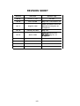
REVISION SHEET
Revision
Issue Date
Revision Page
Rev. A
January 8, 1993
1st issue
Rev. B
June 28,1993
Page 1-23, 1-31,2-22,3-11 ,4-1
Rev. C
August 5, 1993
Added information for the Cl 08
MAIN-B board: Page B-i, B-1,
through B-10
Rev. D
February 28, 1994
Rev. E
April 4, 1995
- vii -
Page 1-33
Added information for the
EPL-5200+: Page C-i, C-1
through C-10
TABLE OF CONTENTS
CHAPTER 1.
CHAPTER 2.
CHAPTER 3.
CHAPTER 4.
CHAPTER 5.
CHAPTER 6.
APPENDIX
GENERAL DESCRIPTION
OPERATING PRINCIPLES
DISASSEMBLY AND ASSEMBLY
ADJUSTMENTS
TROUBLESHOOTING
MAINTENANCE
...
- Vlll -
Chapter 1
General Description
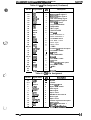
Table of Contents
1.1 FEATURES
1-1
1.2 SPECIFICATIONS
1-5
1.2.1 Basic Specification . . . . . . . . . . . . . . . . . . . . . . . . . . . . . . . . . . . . . . . . .. .1-5
1.2.2 Electrical Specifications . . . . . . . . . . . . . . . . . . . . . ..................1-7
1.2.3 Reliability Specifications . . . . . . . . . . . . . . . . . . . . . ..................1-7
1.2.4 Environmental Conditions for Operating (Include Imaging Cartridge) .. ..1-7
1.2.5 Environmental Conditions for Storage and Transportation (Exclude
Imaging Cartridge) . . . . . . . . . . . . . . . . . . . . . . . . . . . . . . . . . . . . . . . . . . ......1-7
1.2.6 Applicable Standards . . . . . . . . . . . . . . . . . . . . . . . . .................1-8
1.2.7 Specifications for Consumable (Imaging Cartridge) . .................1-8
1.2.8 Physical Specifications . . . . . . . . . . . . . . . . . . . . . . ..................1-8
1.2.9 Software Specifications . . . . . . . . . . . . . . . . . . . . . . . . ...............1-9
1.3 INTERFACE SPECIFICATIONS
1-14
1.3.1 Parallel Interface. . . . . . . . . . . . . . . . . . . . . . . . . . . . . . . . . . . . . . . . . .. .1-14
1.3.2 Serial Interface (Except for the Action Laser 1000) . . . . . . . . . . . . .....1-16
1.3.3 Optional interface C82305*/C82306* (Action Laser 1000 Only) . . .....1-18
,. ,.
(
,
. ..?
b
1-19
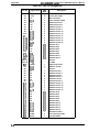
1.4 OPERATING INSTRUCTIONS
1.4.1 Control Panel . . . . . . . . . . . . . . . . . . . . . . . . . . . . . . . . . . . . . . . . . .....1-19
1.4.2 SelecType Functions . . . . . . . . . . . . . . . . . . . . . . . . . . . . . . . . . . . .....1-21
1.4.3 Displayof Messages . . . . . . . . . . . . . . . . . . . . . . . . . . . . . . . . . . . . .. ..1-24
1.4.3.1 Status Messages . . . . . . . . . . . . . . . . . . . . . . . . . . . . . . . . .....1-24
1.4.3.2 Error Messages . . . . . . . . . . . . . . . . . . . . . . . . . . . . . . . . . .....1-25
1.4.3.3 Power On Display . . . . . . . . . . . . . . . . . . . . . . . . . . . . . . . .....1-26
1.4.4 Printer Sharing . . . . . . . . . . . . . . . . . . . . . . . . . . . . . . . . . . . . . . . . .....1-27
1.4.4.1 individual Mode . . . . . . . . . . . . . . . . . . . . . . . . . . . . . . . . . .....1-27
1.4.4.2 Auto Sense Mode . . . . . . . . . . . . . . . . . . . . . . . . . . . . . . . . .. ..1-28
1.4.4.3 Data Receive Buffer . . . . . . . . . . . . . . . . . . . . . . . . . . . . . . .. ...1-28
1.4.5 Controller RAM Status . . . . . . . . . . . . . . . . . . . . . . . . . . . . . . . . . . .....1-29
1.4.6 Optional Memory . . . . . . . . . . . . . . . . . . . . . . . . . . . . . . . .. ... ... ... .~-30
1.4.7 Emulation Mode Switch Function . . . . . . . . . . . . . . . . . . . . . . . . . . .....1-31
1.4.7.1 Emulation Switch by SPL. . . . . . . . . . . . . . . . . . . . . . . . . . .....1-31
1.4.7.2 Intelligent Emulation Switch . . . . . . . . . . . . . . . . . . . . . . . . .....1-31
1.4.8 Resolution Improvement Technology. . . . . . . . . . . . . . . . . . . . . . . .. ...1-32
1.4.9 EEPROM Reset . . . . . . . . . . . . . . . . . . . . . . . . . . . . . . . . . . . . . . . .....1-33
1-34
1.5 MAIN COMPONENTS
1.5.1 C108 MAIN Board . . . . . . . . . . . . . . . . . . . . . . . . . . . . . . . . . . . . . . . . . .1-35
1.5.2 C82907*ROM-B Board (pCL5/RITech Upgrade Board) . .. .. . . . .....1-36
1.5.3 Control Panel . . . . . . . . . . . . . . . . . . . . . . . . . . . . . . . . . . . . . . . . . .. ...1-37
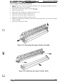
1.5.4 PWB-A Board . . . . . . . . . . . . . . . . . . . . . . . . . . . . . . . . . . . . . . . . . .. ...1-38
1.5.5 PWB-E Board . . . . . . . . . . . . . . . . . . . . . . . . . . . . . . . . . . . . . . . . . .. ...1-38
1.5.6 PWB-F Board . . . . . . . . . . . . . . . . . . . . . . . . . . . . . . . . . . . . . . . . . .. ...1-39
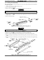
1.5.7 PRINTHEAD UNIT . . . . . . . . . . . . . . . . . . . . . . . . . . . . . . . . . . . . . . . . ..1-39
1.5.8 FUSING UNIT . . . . . . . . . . . . . . . . . . . . . . . . . . . . . . . . . . . . . . . . . .....1-40
Rev. A
l-i
1.5.9 Drive Unit . . . . . . . . . . . . . . . . . . . . . . . . . . . . . . . . . . . . . . . . . . . . . . . . . 1-40
1.5.10 IMAGING CARTRIDGE.. . . . . . . . . . . . . . . . . . . . . . . . . . . . . . . . . . . . 1-40
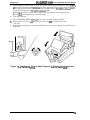
1.5.11 Lower Paper Cassette . . . . . . . . . . . . . . . . . . . . . . . . . . . . . . . . . . . . . . 1-41
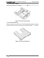
1.5.12 Face Up Output Tray. . . . . . . . . . . . . . . . . . . . . . . . . . . . . . . . . . . . . . . 1-41
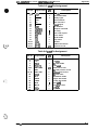
List of Figures
Figure 1-1. Exterior View of the EPL-5000/5200 and Action Laser 1000/1500 . 1-1
Figure 1-2. Printable Area . . . . . . . . . . . . . . . . . . . . . . . . . . . . . . . . . . . . . . . . . . 1-6
Figure l-3. Signal Timing . . . . . . . . . . . . . . . . . . . . . . . . . . . . . . . . . . . . . . . . . 1-14
Figure l-4. Control Panel . . . . . . . . . . . . . . . . . . . . . . . . . . . . . . . . . . . . . . . . . 1-19
Figure l-5. SelecType Levell Menu Map . . . . . . . . . . . . . . . . . . . . . . . . . . . . 1-21
Figure l-6. SelecType Levell in LJ-2P&3/P/Si Menu Map . . . . . . . . . .....1-21
Figure l-7. SelecType Levell in Epson GU2Mode Menu Map . . . . . . .....1-22
Figure l-8. SelecType Levell in LQand FXMode Menu Map . . . . . . . . . . . . 1-22
Figure l-9. SelecType Level 2 . . . . . . . . . . . . . . . . . . . . . . . . . . . . . . . . . . . . . 1-23
Figurel-10.individual Mode . . . . . . . . . . . . . . . . . . . . . . . . . . . . . . . . . . . . . . . 1-27
Figure l-n. Auto Sense Mode . . . . . . . . . . . . . . . . . . . . . . . . . . . . . . . . .....1-28
Figure l-12. Receive Buffer Allocation . . . . . . . . . . . . . . . . . . . . . . . . . . . . . . . 1-28
Figure 1-13. Emulation Switch by SPL . . . . . . . . . . . . . . . . . . . . . . . . . . .....1-31
Figurel-14.intelligent Emulation Switch . . . . . . . . . . . . . . . . . . . . . . . . . . . . . 1-31
Figure 1-15. Effect of RITech . . . . . . . . . . . . . . . . . . . . . . . . . . . . . . . . . .....1-32
Figure l-16. RITech Adjustment . . . . . . . . . . . . . . . . . . . . . . . . . . . . . . . . . . . . 1-32
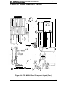
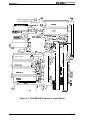
Figure l-17. Component Layout . . . . . . . . . . . . . . . . . . . . . . . . . . . . . . . . . . . . 1-34
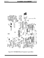
Figure l-18. C108MAlN Board . . . . . . . . . . . . . . . . . . . . . . . . . . . . . . . . . . . . . 1-35
Figure 1-19. C82907*ROM-B Board . . . . . . . . . . . . . . . . . . . . . . . . . . . . .....1-36
Figure l-20. Control Panel . . . . . . . . . . . . . . . . . . . . . . . . . . . . . . . . . . . . . . . . 1-37
Figure l-21. PWB-A Board . . . . . . . . . . . . . . . . . . . . . . . . . . . . . . . . . . . .....1-38
Figure 1-22. PWB-E Board . . . . . . . . . . . . . . . . . . . . . . . . . . . . . . . . . . . . . . . . 1-38
Figure 1-23. PWB-F Board . . . . . . . . . . . . . . . . . . . . . . . . . . . . . . . . . . . . . . . . 1-39
Figure 1-24. PRINTHEAD UNIT . . . . . . . . . . . . . . . . . . . . . . . . . . . . . . . .....1-39
Figure 1-25. FUSING UNIT . . . . . . . . . . . . . . . . . . . . . . . . . . . . . . . . . . . . . . . . 1-40
Figure l-26. Drive Unit . . . . . . . . . . . . . . . . . . . . . . . . . . . . . . . . . . . . . . .....1-40
Figure 1-27. IMAGING CARTRIDGE . . . . . . . . . . . . . . . . . . . . . . . . . . . .....1-40
Figure l-28. Lower Paper Cassette . . . . . . . . . . . . . . . . . . . . . . . . . . . . . . . . . 1-41
Figure l-29. Face Up Output Tray . . . . . . . . . . . . . . . . . . . . . . . . . . . . . . . . . . 1-41
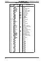
List of Tables
Table -1. Differences in Features . . . . . . . . . . . . . . . . . . . . . . . . . . . . . . . . . . . 1-2
Table -2. Options for EPL-5000/5200 and Action Laser 1000/1500 . ........1-3
Table -3. PaperFeed Methods . . . . . . . . . . . . . . . . . . . . . . . . . . . . . . . .. ....1-5
Table -4. Paper Types . . . . . . . . . . . . . . . . . . . . . . . . . . . . . . . . . . . . . . . . . . . . 1-5
Table l-5. Usabilityof Special Papers . . . . . . . . . . . . . . . . . . . . . . . . . . . . . . . . 1-6
Table l-6. Electrical Specifications . . . . . . . . . . . . . . . . . . . . . . . . . . . . . . .. ...1-7
Table 1-7. Differences between EPSON GL/2 and GU2 in the HP LaserJet@
lli/lllP/illSi Emulation . . . . . . . . . . . . . . . . . . . . . . . . . . . . . . . . . . . . . . . . . . . . . . 1-9
Table 1-8. Built-in Fonts (EPL-5000/Action Laser 1000). . . . . . . . . . . . . .....1-10
Table l-9. Built-in Fonts (EPL-5200/Action Laser 1500 and EPL-5000/Action
Laser 1000 with PCL5@ Board . . . . . . . . . . . . . . . . . . . . . . . . . . . . . . . . .....1-10
Table 1-10. Built-in Fonts (EPL-5000 with GQ Chip) . . . . . . . . . . . . . . . . . . . . 1-11
l-ii
Rev. A
Table 1-11. Built-in Fonts (EPL-5200 with GQ Chip Option and EPL-5000 with
PCL5@ Board and GQ Chip) . . . . . . . . . . . . . . . . . . . . . . . . . . . . . . . . . . .....1-12
Table 1-12. Signal Timing . . . . . . . . . . . . . . . . . . . . . . . . . . . . . . . . . . . . . . . . ..1-14
Table l-13. Centronics@ Parallel Interface Pin Assignment . . . . . . . . . . . . . . .1-15
Table l-14. Serial interface Connector Pin Assignments . . . . . . . . . . . . .....1-16
Table 1-15. Status Messages . . . . . . . . . . . . . . . . . . . . . . . . . . . . . . . . . . .....1-24
Table 1-16. Error Messages . . . . . . . . . . . . . . . . . . . . . . . . . . . . . . . . . . . . . . . . 1-25
Table l-17. Displayat Power on . . . . . . . . . . . . . . . . . . . . . . . . . . . . . . . .....1-26
Tabiel-18. RAM Chip Combinations . . . . . . . . . . . . . . . . . . . . . . . . . . . . .....1-30
Table l-19. Differences in Components forthe C108 MAIN Board . . . . . .....1-36
Rev.A
l-iii
EPL4M#52tW/Act&n faser l@W’lSIM Service Manual
Genera/Description
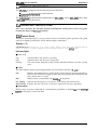
1.1 FEATURES
The EPL-5000/5200 and the ActionLaser 1000/1500 are non-impact page printers that combine a
semi-conductor laser with electro-photographic technology. ‘Ihese printers are small and light, and
feature high-speed, high-resolution printing. Also, maintenance is very easy, as a result of various
built-in diagnostic functions. The main features are:
it
No ozone
L1
Printing speed —6 PPM
[d
Resolution —3W DPI
c1
Light weight — about 10 kg (22 lb.)
ii
c1
Small footprint
Face-down tray (standard) /face-up tray (optional)
c1
High-performance controller (the controller’s CPU is a 16.67 MHz Motorola 68000)
Q
Easy maintenance
EPL-5000/ActionLaser 1000 has HP LaserJet@ 11P emulation mode
o
c1
c1
EPL-5200/ActionLaser 1500 has HP LaserJet@ 111/IIIP/IIISi emulation mode
emulanon‘“
moae
EPL-5000/ActionLaser 1 0 0 0 c a n b e u p g r a d e d f r o m H PW LaserJet@
‘ ‘- ‘ to
.
PCL5
/RITech
Upgrade
LaserJet@ 111/IIIP/IIISi emulation mode with the optional Epson
Board
c1
Optioml PostScript’” IC card
Optional Epson GL identity IC card
High-speed serial communication rate of 38400 bps (except for the ActionLaser 1000)
c1
A multi-user, multi-emulation mode
Cl
Various types of fonts available in font cards and cartridges
LI
IES (Intelligent Emulation Switch) allows switching of the printer mode between PostScript’”
mode and another mode
o
SPL (Shared Printer Language) enables switching of the printer mode by command
In the EPL-5200/ActionLaser 1500 and in the EPL-5000/ActionLaser 1000 with the optional
Epson PCL5/RITech Upgrade Board, Resolution Improvement Technology (RITech) ~efines
the print quality by eliminating jagged edges from images and characters.
c1
a
cl
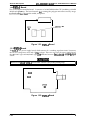
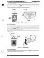
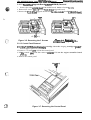
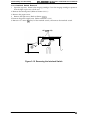
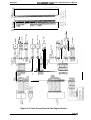
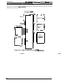
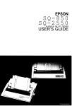
Figure 1-1 shows an exterior view of the EPL-5000/5200 and ActionLaser 1000/1500.
Figure 1-1. Exterior View of the EPL-5000/5200 and
Action Laser 1000/1500
Rev. A
1-1
EPL-5000/5200/Action Laser iOOOl1500 Service Manual
General Description
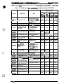
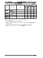
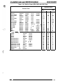
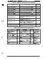
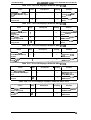
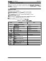
Table 1-1 shows the differences in featires for tie EpL-5000, Actionhser 1000, EPL-5000 with the
optional Epson PCL5/RITech Upgrade Board, ActionLaser 1000 with the optional Epson
PCL5/RITech Upgrade Ward, EpL-5200, and ActionLaser 1~.
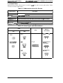
Table 1-1. Differences in Features
Function/
Specification
EPL-5000
HP LaserJet@
Emulation
Level
Action
Laser
EPL-5000
with
Action Laser
1000 with
EPL%2M
Action Laser
1000
PCL5°
Board
PCL5@
Board
LaserJet@
11P
(PCL4C”)
LaserJet@
11P
(PCL4@)
LaserJe{~
111/l llP/lllSi
(PCL5@’)
LaserJet@
I 11/lllP/lllSi
(PCL5@)
LaserJet@
111/l llP/lllSi
(PCL5~
LaserJet@
111/lllP/lllSi
(PCL5@)
GQ mode
Optional
No
Optional
No
Optional
No
Local
Language
ROM
No
No
Optional
No
Optional
No
Standard
RAM Size
0.5MB
0.5MB
0.5MB
0.5MB
1.OMB
1.OMB
Maximum
RAM Size
(Optional
RAM chips
installed)
6.5MB
6.5MB
6.5MB
6.5MB
5.OMB
5.OMB
Standard lfF
Parallel/
RS-232C
Parallel
Parallel/
RS-232C
Parallel
Parallel/
RS-232C
Parallel/
RS-232C
Optional lfF
Cards
Type-B IIF
Cards
(Except
C82305*,
C82306*
and
C82313*)
Type-B IIF
Cards
(Include
C82305* &
C82306*
and except
C82313*)
Type-B IIF
Cards
(Except
C82305*,
C82306*
and
C82313*)
Type-B l/F
Cards
(Include
C82305* &
C82306*
and except
C82313*)
Type-B l/F
Cards
(Except
C82305*,
C82306*
and
C82313*)
Type-B l/F
Cards
(Except
C82305*,
C82306*
and
C82313*)
RITech
No
No
Yes
Yes
Yes
Yes
Resident
Bitmap Fonts
9 Portrait
Fonts and
None
Landscape
Fonts
(Note)
9 Portrait
Fonts and
None
Landscape
Fonts
(Note)
9 Portrait
Fonts and 7
Landscape
Fonts
9 Portrait
Fonts and 7
Landscape
Fonts
9 Portrait
Fonts and 7
Landscape
Fonts
9 Portrait
Fonts and 7
Landscape
Fonts
No
13 fonts
13 fonts
13 fonts
13 fonts
Resident
No
Scalable Fonts
Note:
1-2
1500
..
Landscape fonts are generated from portrait fonts by frmware.
Rev. A
EPL&XW52(W/Act&n Laser l(XXU1500 Senrice Manual
Geneml Descdption
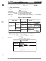
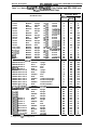
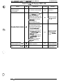
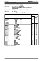
Table 1-2 lists the optional units available for the EPL-5000/Action Laser MlO, and EPL-52@/
Action Laser IWO.
Table 1-2. Options for EPL-5000/5200 and Action Laser 1000/1500
Machine Type
Cat. No.
Note
I
EPLEPL5000 I 52~
Action
Laser
,m
Action
Laser
,W
i400 -54091 Bit map font card
For GQ mode (5400
Prestige 12N/L, 15N/L,
12 NOB are usable in
ESC/P@ mode)
1410-5414 HP bit map font card
For HP emulation mode
Yes
Yes
Yes
Yes
OCFVBAR-CODE
font card
For HP IJJ and GQ
mode (OCR-NB fonts
are also usable in
ESC/P@ mode)
Yes
Yes
Yes
Yes
C828031
22 scalable font card
For GQ mode
Yes
Yes
(Note 1) (Note 1)
C82608*
51 scalable font card
For HP UJ Ill mode
Yes
(Note 3)
C82609*
PostScript’” card
supports Postscript’”
language
Yes
Yes
Yes
Yes
(Note 4) (Note 4) (Note 4) (Note 4]
C82602*
EPSON GL Identity
~rd
Supports HP-GL
commands
Yes
Yes
Yes
Yes
(Note 4) (Note 4) (Note 4) (Note 4]
C82322*
Epson PCL5/
RITech Upgrade
Board
HP LaserJet@
111/l llP/lllSi emulation
mode (includes
EPSON GIJ2 mode)
and RITech support
--
GQ chip ROM
Supports GQ mode
fonts and commands
Yes
Yes
(Note 5) (Note 5)
‘
0
‘
0
.-
Local language ROM
supports local
Ianguage fonts
Yes
(Note 5) (N%5)
‘
0
‘
0
5430
.0:.,.
Description
Yes
Yes
Yes
Yes
(Note 1), (Note 1) (Note 2) (Note 2;
Yes
‘es
No
‘
0
(N%S3)
Yes
‘
0
‘es
No
C82904*
0.5MByte RAM chips 0.5MByte RAM chip set
Yes
Yes
Yes
Yes
C82905*
2. OMByte RAM chips 2. OMByte RAM chip set
Yes
Yes
Yes
Yes
~812302
250 sheet lower
paper cassette (A4)
Lower paper cassette
Yes
Yes
No
No
~812301
250 sheet lower
paper cassette (A/L)
Lower paper cassette
No
No
Yes
Yes
C81231•
Face-up tray
Yes
Yes
Yes
Yes
SO51O11
Imaging cartridge
Yes
Yes
Yes
Yes
282305’/
:82306’
Serial interface card
No
No
Yes
No
>82307’/
;82308”
32KB serial interface
card
Yes
Yes
Yes
Y e s
Toner cartridge
.,
7
Rev. A
1-3
General Descri@ion
EPL-5000/5200/Action Laser 100WI5OO Service Manual
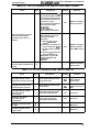
Table 1-2. Options for EPL-5000/5200 and Action Laser 1000/1500 (Con’t)
Machine Type
Cat. No.
Description
Note
Action
Action
5200
Laser
1000
Laser
1500
Yes
Yes
Yes
Yes
rM
C82312*– LocalTalk card
Yes
Yes
Yes
Yes
C82313*
32KB IEEE-488
interface card
No
No
No
No
C82314*
COAX interface card
Yes
Yes
Yes
Yes
C82315*
TWINAX interface
card
Yes
Yes
Yes
Yes
C8231 0’/
C82311“
32KB parallel
interface card
EPL-
EPL-
5000
Notes:
1.
GQ mode fonts can be used, if the optional GQ chip is installed.
2. The ActionLaser 1000/1500 uses only card 5400.
3. Scalable fonts for HP LaserJet III mode can used, if the optional Epson PCI-i5/RITech Upgrade
Board is installed.
4.
Requires added memory (RAM) over a total 1.5 MB (including standard RAM).
5. The GQ ROM chip option and local language ROM camot be used at the same time.
Genemlf)esctfptlon
EPL4WiX.Y52tXl/A ction Laaar 1(XW7SO0 Sanka Manual
1.2 SPECIFICATIONS
This section provides statistical data for the EPL-5000/52~ and ActionLaser lW3/l!MO.
1.2.1
Basic Specifications
Printing method:
Laser beam scanning and dry ekctro-photography
Resolution:
300 DP1 (dots per inch)
Printing speed:
6 PPM (pages per minute) (Ietter/A4)
First printing time (A4/LT):
Less than 19 seconds (facedown output)
Less than 20 seconds (face-up output)
Warm-up time:
Less than 35 seconds (at rated current and 23° C (73° F) temperature)
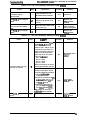
Paper supply:
See Table 1-3.
Table 1-3. Paper Feed Methods
Capaoity
(2011$7(7#m2)
Paper Supply
Standard built-in
paper bin
Lower paper cassette (Optional)
Uaage Thkkneaa
(Beam Weight)
150
A4,LT,GLT,EXE,
LG,GLG
16 to 24 lb.
(60to 90g/m2)
!5 to 10
Monarch,D1.,C5,
Commercial-10
Envelopes made
of 20 to 24 lb. (75
to 90gfm2) paper
1
Any size feedable
(Note 2)
16 to 42 lb.
(60to 157g/m2)
250
A4 or LT
16 to 24 lb.
(60to 90g/m2)
Auto feed
Manual feed
Paper Size
I
I
●
Notes:
lb. (ream weight) = 500 sheets of 17x 22 inch paper; 1 g/m 2 = 0.2659763 lb.
3.63to 8.5 inches (92t0216mrn)
2. Paper size range: width
length
5.85 to 14.0 inches (148.5 mm to 356 mm)
1.
....
(
.-”.,
:. ,
*Y
See Table 14
Paper types:
Table 1-4. Paper Types
I
Standard paper
Xerox” 4024 W paper
20 lb. (75 dm2)
Normal paper
Regular photocopier paper
Bond paper
16 to 24 lb. (60 to 90 g/m2)
Card stook (90 to 157 @m*)
Envelopes
Special papers
Labefs
Letterhead
Transparency (OHP) sheets
Colored oaoer
, :;.%
c)
Rev. A
1-5
EPL-5000/5200 /Action Laser 1000/1500 Service Manual
General Description
See Table 1-5.
Usability of special papers:
Table 1-5. Usability of Special Papers
output
input
OHP
Envelopes
Labels
‘
Standard
built-in paper
bin
Face down
P
P
Face up
R
R
Lower paper
cassette
Face down
I
T
Face up
I
{
Card Stock
Letterhead
.#Y-
R
R
;
I
“+
1
I
;
I
P
P
R: Reliable feeding and good image quality.
P: Possible, but better avoided.
I: Impossible.
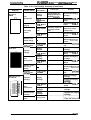
Paper feed alignment and direction:
Paper ejection:
Output tray capacity:
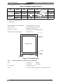
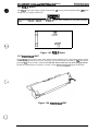
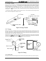
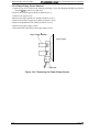
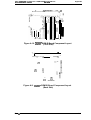
Printable area (standard paper):
Center alignment for all sizes
Face down; face up (optional)
100 sheets (face down)
20 sheets (face up) (standard paper)
See Figure 1-2.
—
Printable Area
—
I
4.00mm
4.00mm
,
. —
Figure 1-2. Printable Area
Note:
The actual printable area depends on the printer mode.
Noise:
Ozone density:
Toxicity:
1-6
Less than 35 dB(A) (standby)
Less than 47 dB(A) (operating)
Less than 0.01 ppm
No toxicity exists in OPC, toner, or plastic materials
Rev. A
General Dascriptfon
EPL-500W5200 /Action Laser 1UOW1500 Semfca Manual
1.2.2 Electrical Specifications
Table 1-6. Electrical Specifications
I
I
I
,
Description
I
1
I
100 V Version
I
200 V Version
Rated voltage
100-120 VAC
220-240 VAC
Input voltage range
90-132 VAC
198-264 VAC
Rated frequency range
50-60 Hz
Input frequency range
47-63 Hz
5.5 A
Rated current
,
3.3 A
Less than 600 W
Power consumption
I
I
1.2.3 Reliability Specifications
MPBF (Mean Prints Between Failures): Over 25,000 Sheets
(;:~
Note:
MP13F indicates average number of pages printed before occurrence of problem requiring
replacement or semice.
-.”
MTBF (Mean Time Between Failures):
Jam rate:
Feed failure:
Multiple paper feeds:
Paper curl height:
Leading edge bending (1 cm or more):
MTTR (Mean Time To Repair):
Durability:
3000 Power on hours (pOH)
1 out of 2~ sheets or less (excluding multiph+sheet feeding)
1 out of 2,000 sheets or less (excluding multiple-sheet feeding)
1 out of 500 sheets or less
30 mm (1.2 inches) or less
1 out of 1,000 sheets
30 minutes or less
5 years or 180,0000 sheets
1.2.4 Environmental Conditions for Operating (Include Imaging Cartridge)
(
.>
Temperature:
10to35‘C (50 to 95 ‘F)
Humidity:
15 to 85
Altitude:
2~ m (8z@ feet) or lower
Levelness:
Illurninance:
Printer should be installed on a level plane.
3,000 IUX or less (Must not be exposed to direct sunlight.)
Surrounding space:
Printer should have at least 100 mm clearance on its sides
and rear.
YOM-I
1.2.5 Environmental Conditions for Storage and TranspoMion
(Exclude Imaging Cartridge)
Temperature:
Oto35‘C (32 to 95 “F) over full storage term
-20 to55“C (4 to 131 “F) under extreme conditions
(Extremes are allowable for up to l/300f full storage term)
Temperature variation must be10‘C (18 ‘F) jhour or less
Humidity:
30to85‘%oRH over full storage term
10 to 95 YoRH under extreme conditions
(Extremes are allowable for up to 1/30 of full storage term)
Drop test:
Vibration:
Clear to JIS Z0200-1987 Level 1
5 to IW Hz and 100 to 5 Hz
Vibration frequency
IG
Acceleration
Accelerationdirection 3direction
Resistance to atmospheric pressure:
More than 613 mb
Storage term:
24 months (following date of manufacture)
Rev. A
1-7
General Description
EPL-5000/5200/A ction Laser 1000/1500 Service Manual
1.2.6 Applicable Standards
Safefy %ndurds
120 VAC model:
220/240 VAC model:
UL 1950, CSA 22.2 Deviation 220
EN 60950 (IEC950), NEMKO (IEC950), SETI (I EC950),
SEMKO (IEC950), DEMKO (IEC950)
Safety Regulations (Laser radiation)
120 VAC model:
z20/240° VAC model:
FDA(NCDRH) Class 1
VDE O&37 (Laser Class 1)(IEC825), SETI (IEC825), SEMKO
(IEC825), DEMKO (IEC825)
EMI
120 VAC model:
220/240 VAC model:
FCC Part 15 Subpart B Class B
FTZ (VDE 0871 Class B, 0875 Part 1), CISPR Pub22
Others
No effect human health. (OSHA-TSCA, EINECS)
No effect human health. (OSHA)
Less than 0.01 mmp
other UL478 (5th edition)
SWISS Environmental Law (No CdS must be contained)
Toner:
OPC:
Ozone:
Materials:
1.2.7 Specification for Consumable (Imaging Cartridge)
Life:
Note:
6,000 pages
In continuous printing mode with A4/letter paper at a 5% image ratio (blacldwhite ratio).
The life varies, depending on the printing mode (continuous or intermittent) anoXor the
image ratio.
Environmental Conditions for Storage and Transportation
Temperature:
Oto30“C(32 to 86 ‘F) over full storage term
-20 to40“C (-4 to 104 “F) under extreme condition
(Extremes are allowable for up to 1/30 of full storage term)
Temperature variations must be10“C (18 OF)/hour or less.
Humidity:
30 to 85 YoRH over full storage term
10to95‘%oRH under extreme conditions
(Extremes are allowable for up to 1/30 of full storage term)
Drop test:
Vibration:
Resistance to atmospheric pressure:
Storage term:
Height 76 cm (30.4 inches)
Same as printer
More than 740 mb
18 months (following date of manufacture)
1.2.8 Physical Specifications
Dimensions:
Printer:
With lower cassette:
With face-up tray:
With lower cassette and
face-up tray:
Weight:
With lower cassette;
With face-up tray;
With lower cassette and
face-up tray;
l-a
3 6 8 ( W ) X 4 5 6 ( D ) X 226(H)mm
14.5(W) x 18.O(D) x 8.9(H) inches
368(W) x 480(D) x 336(H) mm
14.5(W)X
368(W) x
14.5(W)X
368(W) x
18.9(D) x 13.2(H) inches
6 3 2 ( D ) x 360(H)mm
24.9(D) x 14.2(H) inches
657(D) X 430(H) mm
14.5(W) x 25.9(D) x 16.9(H) inches
Approx. 10 Kg (22 lb.) (consumable, excluding all options)
Approx. 12.8 Kg (28.3 lb.)
Approx. 10.1 Kg (22.3 lb.)
Approx. 12.9 Kg (28.6 lb.)
Rev. A
GenetalDescdption
EPL&lWW52U0/Actfon Laser 1OO(W5OO Sarvfce Manual
1.2.9 Software
Specifications
HP LaserJet@ 11P emulation: (EPL-5000/ActionLaser 1000)
HP LaserJet@ 111/lllP/IIISi emulation mode: (EPL-5200/ActionLaser 1500)
Epson GL/2 mode (LJ3-GL/2 mode and GL-like mode):
(EPL-5200/ActionLaser 1500)
ESC/~ 9-pin (FX-86e/286e, FX-800/1000) emulation mode
ESC/ P@ 24-pin (LQ-25UO) mode
Built-in modes:
Note:
GL/2 mode is similar to the GL/2 mode included in the HP La~rJet@
111/llIP/lIISi emulation. Table 1-7 shows the differences between Epson GL/2 mode and
the GL/2 mode in the HP LaserJet@ 111/lIIP/IIISi emulation. While in Epson GL/2 mode,
the operator can enter GL/2 mode without sending the ESC Yo#B (Enter GL/2 mode)
command. If the operator’s application software cannot send the ESC ‘Yo#B command,
The Epson
then use this mode.
-
Table 1-7. Differences between EPSON GU2 and
GL/2 in the HP LaserJet” IIUlllP/lllSi Emulation
GU2 for HP LaserJet@
lli/lllP/illSi Emulation Mode
EPSON GLJ2 Mode
PCL mode
PaDer eiect
I Exists as the initial mode
Does not exist
I
I
\ SUPPOrtS PG, AFcommands I Supported inPCL
Auto eject
SelecType setting
Not available
Reduced printing
SeiecType setting
Avaiiable in PCL
I
Switch to PCL
Not SUppOftf3d
supported
Reset (ESC E)
Ejects paper and then
initializes
Ejeots paper, switches to PCL,
and then initializes
PJL, EJL, and ES
Supported
supported
Advance Full Page
(PG. AF)
Supfmled
Not SUppOrtt3d
(ESC %#A)
Notes:
.r. .
‘3
,(
.. .;,
EPSON GL/2 mode has two operational modes. One is LJ3-GL/2 mode; the other is the
GL-like mode.
LJ3-GL2 mode emulates the GL/2 mode in the HP LaserJet@ 111/IIIP/IIISi emulation. ‘l’he
user can print with software that supports the HP 76MI series plotter.
The GL-like mode features all the co remands of the LJ3=L/2 mode, plus two additional
commands. The GL-like mode emulates some of the HP-GL plotter (HP 7475A, etc.)
commands. If the application software uses unsupported co remands for the GL-like
mode, print cannot be assured.
HP LaserJet@ 111/IIIP/IIISi emulation (EPL-5000/ActionLaser 1000)
Optional modes:
EPSON GL/2 (EPL-5000/ActionLaser 1000)
Page Prin$~r mode (GQ mode) (EPL-5000/5200)
Postscript mode (all models)
EPSON GL mode (all models)
Auxiliary software:
Hex dump
Status sheet
Font sampie
Built-in fonts:
See Table 1-8 through Table 1-11.
,o+.
‘$J..
‘.,.
Rev. A
1-9
EPL+OOO/5200/Action Laser 1000/1500 Service Manual
General Description
Table 1-8. Built-in Fonts (EPL-5000/Action Laser 1000)
Resident Fonts
=
Bitmap fonts
Courier
Medium
Upright
10 cpi
Courier
Courier
Courier
Courier
Courier
Line printer
Presitage
Presitage
Bold
Medium
Medium
Bold
Medium
Medium
Medium
Medium
Upright
Italic
Upright
Upright
Italic
Upright
Upright
Umiaht
10 cpi
10 cpi
12 cpi
12 cpi
12 cpi
16.66 cpi
12 cpi
20 c~i
Portrait
Portrait
Portrait
Portrait
Portrait
Portrait
Portrait
Portrait
Portrait
s
s
s
s
s
s
s
NS
Ns
s
s
NS
s
s
NS
s
s
s
i: Supported, NS: Not Supported
Table 1-9. Built-in Fonts (EPL-5200/Action Laser 1500 and EPL-5000/Action
Laser 1000 with PCL5@ Board)
Applicable Mode
Resident Fonts
Bitmap fonts
Courier
Courier
Courier
Courier
Courier
Courier
Courier
Courier
Courier
Courier
Courier
Medium
Bold
Medium
Medium
Bold
Medium
Medium
Bold
Medium
Medium
Bold
Medium
Medium
Medium
Medium
Medium
Courier
Line printer
Line printer
Presitage
Presitage
Scalable fonts for PCL@
Medium
EPSON Roman T
EPSON Roman T
Bold
EPSON Roman T
Medium
EPSON Roman T
Bold
EPSON Saris Serif U
Medium
EPSON Saris Serif U
Bold
EPSON Saris Serif U
Medium
EPSON Saris Serif U
Bold
EPSON Saris Serif U
Medium
EPSON Saris Serif U
Bold
EPSON Saris Serif U
Medium
Bold
EPSON Saris Serif U
Medium
ITC Zapf Dinqbatts@
Upright
Upright
Italic
Upright
Upright
Italic
Upright
Upright
Italic
Upright
Upright
Italic
Upright
Upright
Upright
Upright
Upright
Upright
Italic
Italic
Upright
Upright
Italic
Italic
Condensed
Condensed
Condensed
Condensed
Upright
10 cpi
10 cpi
10 cpi
10 cpi
10 cpi
10 cpi
12 cpi
12 cpi
12 cpi
12 cpi
12 cpi
12 cpi
16.66 cpi
16.66 cpi
12 cpi
20 cpi
Portrait
Portrait
Portrait
Landscape
Landscape
Landscape
Portrait
Portrait
Portrait
Landscape
Landscape
Landscape
Portrait
Landscape
Portrait
Portrait
HP LJ3
ESC/P@
s
s
s
s
s
s
s
s
s
s
s
NS
s
s
NS
s
s
s
s
s
s
NS
NS
NS
s
s
s
s
s
s
s
s
s
s
s
s
s
Upright
Upright
Italic
Italic
NS
s
s
s
s
s
s
s
NS
NS
NS
NS
NS
NS
NS
NS
NS
NS
NS
NS
NS
S: Supported, NS: Not Supported
1-1o
Rev. A
Table 1-10. Built-in Fonts (EPL-5000 with GQ Chip)
Applicable Mode
Resident Fonts
Bitmap fonts
Upright
10 cpi
Courier
Medium
Upright
10 cpi
Bold
Courier Bold
Medium
10 cpi
Italic
Courier Italic
Upright
Medium
10 cpi
Courier
Upright
10 cpi
Bold
Courier Bold
Medium
12 cpi
Upright
Courier
12
cpi
Upright
Courier Bold
Bold
12 cpi
Italic
Medium
Courier Italic
16.66 cpi
Upright
Medium
Line printer
16.66 cpi
Upright
Medium
Line printer
12 Cp;
Presitage
Upright
Medium
20 cpi
Medium
Presitage
Upright
13 cpi
Upright
Medium
EDP
13 cpi
Medium
Upright
EDP
10 point
Modern
Medium
Upright
Scabble fonts tbr G(?
Courier
Medium
Upright
Courier
Bold
Upright
Courier
Medium
Oblique
Courier
Bold
Oblique
EPSON Roman T
Medium
Upright
EPSON Roman T
Bold
Upright
italic
EPSON Roman T
Medium
Bold
italic
EPSON Roman T
Medium
EPSON Saris serif H
Upright
EPSON Saris serif H
Bold
Upright
EPSON Saris serif H
Medium
Oblique
Obfique
EPSON Saris setif H
Bold
Uptiaht
EPSON Svmbolic Set
Medium
c,’
r..
Portrait
Portrait
Portrait
Landscap[
Landscap[
Portrait
Portrait
Portrait
Portrait
Landscap[
Portrait
Portrait
Portrait
Landsqx
Portrait
HP LJ21
ESC/P@
GQ
s
s
s
s
s
s
NS
NS
NS
NS
s
s
s
s
s
s
s
s
NS
s
s
s
s
NS
NS
NS
NS
NS
NS
NS
NS
NS
NS
NS
NS
NS
NS
NS
NS
NS
NS
NS
NS
NS
NS
NS
NS
NS
NS
NS
NS
NS
NS
NS
NS
NS
NS
NS
s
s
s
NS
NS
NS
s
s
s
s
s
s
s
s
s
s
s
s
s
s
s
s
s
s
s
s
S: Supported, NS: Not Supported
.-.
Rev. A
1-11
EPL-50011/5200/Action Laser 1000/1500 Service Manual
General Description
Table 1-11. Built-in Fonts (EPL-5200 with GQ Chip Option and EPL-5000 with
PCL5@ Board and GQ Chip)
Applicable Mode
———
Resident Fonts
Bitmap fonts
Medium
Upright
Courier
Bold
Upright
Courier
Italic
Medium
Courier
Medium
Upright
Courier
Bold
Upright
Courier
Italic
Medium
Courier
Upright
Medium
Courier
Bold
Upright
Courier
Italic
Medium
Courier
Upright
Medium
Courier
Bold
Upright
Courier
Italic
Medium
Courier
Upright
Medium
Line printer
Upright
Medium
Line printer
Upright
Medium
Presitage
Upright
Medium
Presitage
Upright
Medium
EDP
Upright
Medium
EDP
Upright
Modern
Medium
Scalable font for PCL@
Medium
EPSON Roman T
Bold
EPSON Roman T
Medium
EPSON Roman T
Bold
EPSON Roman T
Medium
EPSON Saris serif U
Bold
EPSON Saris serif U
Medium
EPSON Saris serif U
Bold
EPSON Saris serif U
Medium
EPSON Saris serif U
Bold
EPSON Saris serif U
Medium
EPSON Saris serif U
Bold
EPSON Saris serif U
Medium
ITC Zapf Dingbatts@
Sca/ab/e fonts for GQ
Medium
Courier
Bold
Sourier
Medium
2ourier
Bold
3ourier
Medium
EPSON Roman T
Bold
=PSON Roman T
Medium
=PSON Roman T
Bold
=PSON Roman T
Medium
~PSON Saris serif H
Bold
EPSON Saris serif H
Medium
=PSON Saris serif H
Bold
;PSON Saris serif H
Medium
;PSON Svmbcdic Set
10 cpi
10 cpi
10 cpi
10 cpi
10 cpi
10 cpi
12 cpi
12 cpi
12 cpi
12 cpi
12 cpi
12 cpi
16.66 cpi
1 6 . 6 6 cpi
12 cpi
20 cpi
13 cpi
13 cpi
10 point
Upright
Upright
Italic
Italic
Upright
Upright
Italic
Italic
Condensed
Condensed
Condensed
Condensed
Upriqht
Upright
Upright
Oblique
Oblique
Upright
Upright
Italic
Italic
Upright
Upright
Oblique
Oblique
Upriqht
Portrait
Portrait
Portrait
Landscap[
Landscapf
Landscap[
Portrait
Portrait
Portrait
Landscap{
Landscap(
Landscap[
Portrait
Landscapf
Portrait
Portrait
Portrait
Landscap(
Portrait
HP LJ3
ESC/P@
s
s
s
s
s
s
s
s
s
s
s
s
s
s
s
NS
NS
NS
NS
NS
s
s
s
s
NS
NS
NS
NS
NS
NS
s
s
s
s
NS
s
s
NS
s
s
s
s
NS
NS
NS
s
s
NS
NS
NS
NS
s
s
s
s
s
s
s
s
s
s
s
s
NS
NS
NS
NS
NS
NS
s
NS
NS
NS
NS
NS
NS
NS
NS
NS
NS
NS
NS
NS
NS
NS
NS
NS
NS
NS
NS
s
s
s
s
s
s
s
s
s
Upright
Upright
Italic
Italic
GQ
s
s
s
s
NS
NS
NS
NS
NS
NS
NS
NS
NS
NS
NS
NS
NS
NS
NS
NS
NS
NS
NS
NS
NS
NS
NS
NS
NS
NS
s
s
s
s
s
s
S: Supported, NS: Not Supported
1-12
Rev. A
EPL@OtY52001Act~n Laser 1000/1500 Service Manual
General Description
Font Symbol Sets
HP LaserJet@ 11P Mode: 26 symbol sets
1S02, 4,6,10,11,14,15,16,17, 21,25,57,60,61,69,84, 85
Roman Extension
HP Spanish
HP Roman-8
IBM-DN
ISO1OO(ECMA94-1 )
HP German
HP Legal
IBM-US
PcMultilingual
HP LaserJet@ III/IIIP/IIISi Mode: 41 symbol sets
1S02, 4,6,10,11,14,15,16,17, 21,25,57,60,61,69,84, 85
ISO1OO(ECMA94-1)
Venture Math
Roman Extension
Venture International
HP German
Venture US
HP Spanish
PS Math
HP legal
PS Text
HP Roman-8
Math 8
IBM-US
Pi Font
IBM-DN
Microsoft Publishing
PcMultilingual
Venture ITC Zapf Dingbatts Windows
DeskTop
PS ITC Zapf Dingbatts
ITC Zapf Dingbatts@ 100
ITC Zapf Dingbatts @ 200
ITC Zapf Dingbatts@ 300
ESC/P Mode: 13 International Characters
USA
FRANCE
GERMANY
UK
DENMARK1
SWEDENT
ITALY
SPAIN1
JAPAN
NORWAY
DENMARK2
SPAIN2
L.AMERICA
(In addition to the above, Code Page 860,863,850,865 and 437 can also be selected by SelecType.)
. . \.,j
( .,
GQ Mode: 35 symbol sets (Option)
*
SPAIN1
USA
JAPAN
FRANCE
*
NORWAY
GERMANY *
*
DENMARK2
UK
SPAIN2
DENMARK1 *
L. AMERICA
SWEDEN
*
ITALY
*
*
*
*
*
*
*
● : Two types, one with extended graphics and one without.
Code
Code
Code
Code
Code
page 865 (PcNordic)
page 850 (PcMultilingual)
Page 437 (PcUSA)
Page 863 (PcCanFrench)
Page 857
Rev. A
Code page 860 (PcPortuguese)
ECMA94-1
Symbolic
Code Page 853
1-13
EPL+OOO/5200/Action Laser 1000/1500 Service Manual
General Description
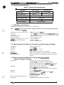
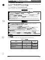
1.3 INTERFACE SPECIFICATIONS
TIW EPL-5000/5200 and ActionLaser 1500 are equipped with the following external interfaces:
H Centronics@ parallel interface
❑ RS-232C interface
■ Optional Type B interface (except for C82305*/C82306*)
The ActionLaser 1000 is equipped with the following external interfaces:
❑
9
Centronics@ parallel interface
Optional Type B host interface (including C82305*/C82306*)
1.3.1 Parallel Interface
Type:
System:
Handshaking:
Note:
CentronicsC>
STROBE synchronization, 8-bit parallel data transfer
BUSY and ACKNOWLEDGE signals
While the SelecType setting for BUSY delay is “MlN,” the handshaking signal is BUSY
only.
Comector type:
Applicable plug:
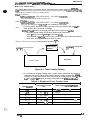
Transfer speed:
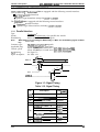
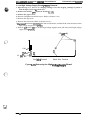
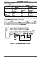
Siamal timing:
Signal description:
P90-25027-1 (Amphenol) receptacle
57-30360 (Amphenol or equivalent)
About 75,000 bytes/second (max.) (EPL-5000/ActionLaser 1000)
About 125,000 bytes/second (max.) (EPL-5200/ActionLaser 1500)
See Figure 1-3.
See Table 1-12.
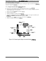
(1)
(
DATA 1-8
):
(2)
‘r
VALID
VALID
, :3) ,
STOROBE
/
(4)
—
<
.
(7)
>
/
BUSY
\
ACKNLG
f
+--+
(6)
Figure 1-3. Signal Timing
Table 1-12. Signal Timing
No.
(1)
Data set up
0.5 (min.)
(2)
DATA hold
0.5 (min.)
(3)
STROBE (pulse width)
0.5 (min.)
(4)
BUSY delay
4.0 (max.)
ACKNLG to BUSY –5
o (typ.)
(5)
1-14
Time (p.sec.)
Description
o
5 (typ.)
+5
10 (typ.)
No ACKNLG pulse
—
(6)
ACKNLG pulse width
10 (typ.)
(7)
ACKNLG to STROBE
O (min.)
Rev. A
Genendl)escrlptjon
EPL+WiXV52(X1/Ac thn Laser l(XXV1500 Service Manual
Table 1-13. Centronics@ Parallel Interface Pin Assignment
~in No.
Signal Name
I/o
Description
STROBE is a strobe pulse used to read data from the host
1
2-9
>.“),
(. .
‘d’
computer. The pulse width must be more than 0.5 psec.
Normally it is HIGH, and data is latched at the tmiling edge of
this signal.
STROBE
IN
DATA 1-8
DATA 1 to 8 are parallel data bits. When the signal is HIGH,
I the data bit is 1, and when it is LOW, the data bit is O.
IN ~ The most
bit (MSB) is DATA8. The signal state
must be maintained for 0.5 psec. on either side of the
STROBE signal active edge.
sjgnif~nt
10
ACKNLG
OUT
ACKNLG is an acknowledge pulse with an approximate width
of 10 @cc. This signal goes LOW when the data reception is
completed, which indicates that the printer can accept new
data. Timing with the BUSY signal is specified through
SelecType.
11
BUSY
OUT
The BUSY signal informs the host computer of the printer
state. When the signal is HIGH, the printer cannot acoept
data.
12
PE
OUT
The PE signal indioates paper empty for the standard
cassette selected through SelecType or command, or for the
option paper cassette. Paper empty is indicatd by HIGH.
13
SLCT
OUT
Pulled up to +5V through a 3.3 Kohm resistor.
14
AUTO-FEED
IN
If the AUTO FEED signal is set to LOW, the printer automagicaliy performs a LF (line fed) upon reoeiving a CR
(Carriage Return) oode from the host computer.
In GQ Mode (option) or ESC/P@ Mode, AUTO-FEED signal
affeots the CR operation according to SeleoType settings. In
HP Mode, AUTO-FEED signal is afways ignored. Deteotion
can only be done when the printer is ON or when active
intetface is switohed to parallel interface.
This signal is detected only when the power is turned ON, or
when the printer is initialized.
15
NC
.
Not used.
16
GND
17
CHASSIS GND
18
NC
Not USeCf.
19-30
GND
Ground level for the twisted pair return signal.
31
~T
32
ERROR
Logio ground level.
-
IN
OUT
Connected to the printer chassis. The printer chassis GND
and the signal GND are connected to each other.
The STROBE signal is ignored when this signal is LOW.
This level goes LOW when the printer is:
● out of paper
● paper jam
●
in error state
●
off line
33
GND
Same as for pins19 to 30.
34
NC
Not USd
35
+5V
Pulled up to +5V through 3.3 Kohm resistance.
Rev. A
1-15
EPLGOOO/5200/Action Laser 1000/1500 Service Manual
General Description
Table 1-13. Centronics@ parallel Interface Pin Assignment (Continued)
~in No.
36
Signal Name
SLCT-IN
1/0
Description
IN
If the SLCT-IN signal is LOW when the printer is turned on or
initialized, the printer enters the seiectecf state. In this state,
DC1 and DC3 control codes are ignored. If the SLCT-IN
signal is HIGH when the printer is turned on or initialized, the
select/deselect control by DC1/DC3 is valid. If the printer
receives a DC3 code, any subsequent data wili be thrown out
until a DC1 code is received. Handshaking with the BUSY or
ACKNLG signai, however, is yerformed for data during this
time. It is possible to disable SLCT-iN signal with SelecType
and keep the printer constantly in the selected state. In GQ
mode (option) or ESC/P@ mode, this signai affects the DC1 or
DC3 operation according to SelecType settings. In HP Mode
this signal always ignored.
1.3.2 Serial Interface (Except for the ActionLaser 1000)
Type:
Transfer system:
Synchronization:
Protocol:
Transfer speed:
Error:
Signal description:
RS-232C
Fuli duplex
Asynchronous start-stop system
1
Start-bit:
1 or 2
Stop-bit:
Data length:
7 bits or 8 bits
Parity:
Odd, even, or none
X-ON/X-OFF (can be combined with DTR control)
DTR control (can be combined with X-ON/X-OFF)
300,600,1200,2400,4800, 9600,19200, or 38400 bps
Processed as missing data and replaced by “*”
Overrun error:
Replaced by “*”
Parity error:
Replaced by “*”
Framing error:
Breaking character: Ignored
See Table 1-14.
Table 1-14. Serial Interface Connector Pin Assignments
>in
No
1
——
Signal Name I 1/0
CHASSIS-GND I
-
Description
Connected to the printer chassis. The printer chassis GND
and the signal GND are connected to each other.
2
Serial ASCII data outputted by the printer. It maintains
“MARK” state (LOW Ievei) between transmitted character
codes. Logic O is at HIGH level (“SPACE”) and logic 1 is at
LOW level (“MARK”).
3
Seriai ASCli data inputted to the printer. it maintains “MARK”
state (LOW level) between received character codes.
4
RTS
OUT
Transmission request signal outputted from the printer. It is
always at HiGH level during power ON.
IN
Response signal to the RTS signal inputted to the printer.
The printer transmits the data through TXD while CTS is
HIGH. It can be fixed HIGH through SelecType.
When the SelecType setting for CTS is ON, X-ON/X-OFF will
not be transmitted if CTS sicmal is LOW.
1
5
1-16
CTS
Rev. A
General Descdption
EPL-500W5200/Actkm Laser llXMdMN) Servloe Manual
Table 1-14. Serial Interface Connector Pin Assignments (Continued)
Pin No
6
—7
8
DSR
I/o
Description
IN
Signal inputted to the printer. The printer can transmit data
through TXD while DSR is HIGH. X-ON/X-OFF, however, can
be transmitted regardless of DSR state. It can always be
ignored by setting SelecType (Factory setting).
Ground reference (O V) for signals.
. SIGNAL GND
9-19
20
(,
Signal Name
DCD
Always ignored.
NC
Not Used.
DTR
Signal outputted by the printer. When the DTR signal is
HIGH, it indicates that the RXD signal can be received by the
printer. The SelecType settings do not speoify DTR control,
the signal level is HIGH while the printer power is on. When
SelecType setting is used for DTR oontrol, DTR goes LOW in
case any of the error conditions.
The date (RXD) from host computer must be stopped within
128 characters after DTR goes LOW.
:-’!
21-25
IN
NC
OUT
Not USd.
Handshaking
When the vacant area for data in the input buffer drops to 128 bytes, the printer outputs an X-OFF
code or sets the DTR signal level to LOW, indicating that the printer cannot receive more data.
Once the vacant area for data in the buffer recovers to 256 bytes, the printer outputs an X-ON code
or sets the DTR flag to HIGH, indicating that printer is again ready to receive data.
Protocol
There are three types of protocols, as listed below, and each of them can be designated by SelecType
independently.
■ DTR/DSR protocol
SelecType is used to execute the DTR/DSR control protocol. The DTR signal is set to HIGH when
the printer is ready to receive data, and to LOW when conditions indicate an error or that the
receiving buffer is fuk
(’. . ‘
1
When the error is cleared and the printer returns to on line mode, the signal returns to HIGH. When
SelecType is used to set the DTR control OFF, DTR is always set HIGH. The printer transmits TXD
only when DSR is at the HIGH level (DSR is always considered HIGH when the SelecType setting
for DSR is OFF). X-ON/X-OFF transmission is independent from the DSR state.
■ X-ON/X-OFF (DC1/DC3) protocol
SelwType is used to execute X-ON/X-OFF protocol. The X-OFF (DC3) code is output if status
indicates an error, and the printer warns the host to stop data transmission within 128 characters.
No further X-OFF codes are sent in response to additional data received from the host after the
X-OFF code has been sent once. The X-ON (lXl) code is output after all conditions given in error
are cleared.
When the remaining capacity of the receive buffer reaches 128 characters, X-OFF (DC3) is output
once. It is sent only once, even if there are multiple errors. The printer goes on line automatically at
power on, and outputs an X-ON code. Transmission of X-ON/X-OFF codes can be defined by
SelecType.
■ ENQ/ACK Protocol
If the EPSON GL mode (optionaf) is selected, ENQ/ACK protocol is also supported.
Rev. A
1-17
General Description
EPL-5(XZV5200/Action Laser 1LWW1500 Service Manual
1.3.3 Optional Interface C82305*/C82306* (ActionLaser 1000 Only)
The ActionLaser 1000 can use the non-intelligent serial interface card C82305*/C82306*.
Type:
Synchronization:
Protocol:
Transfer speed:
Error:
1-18
RS-232C or current loop
Asynchronous start-stop system
Start bit:
1
Stop bit:
1
Data length:
7 bits or 8 bits
Parity:
Odd, even, or none
X-ON/X-OFF (cannot be combined with DTR control)
DTR control (cannot be combined with X-ON/X-OFF)
300,600,1200,2400,4800, 9600, or 19200 bps
Overrun error:
Processed as missing data and replaced by “*”
Parity error:
Replaced by “*”
Framing error:
Replaced by “*”
Breaking character: Ignored
Rev. A
General Daacdption
EPL4WUlY52tN1/Ac tion Laaer 10i7tY1500 Service Manual
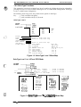
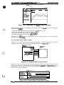
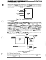
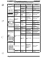
1.4 OPERATING INSTRUCTIONS
This section describes the functions performed through the control panel, such as test print,
hexadecimal dump, and SelecType functions.
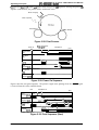
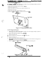
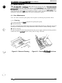
1.4.1 Control Panel
The printer control panel gives you easy control over most common printer operations. The panel
consists of a liquid crystal display (LCD), indicator lights, and buttons.
ON:NE
SelecType
.EVEL 1
imu
RESET
IJ
EXIT
I
LEVEL 2
o
COPY END CONTINUE
0
FEED
Figure 1-4. Control Panel
Display (LCD)
A 20-character (5 x 7 dot matrix) by l-row liquid crystal display (LCD) unit that indicates printer
status. A varie~ of printer parame~ers can be displayed and &t &ing SelecType mode.
Indicator lights
■ ON LINE
c’:\
,1
ON:
OFF:
Flashing:
Communication with the host is possible.
Communication with the host is impossible.
This state occurs when the system cannot shift from off line to on line, or vice versa.
■ FEED
This LED indicates the data processing condition for each interface channel: S, P, and O.
ON:
OFF:
Fast flashing:
Indicates that received data is stored in the printer that has not been printed out.
However, the LED does not light up when only non-printable data (comman ds and
other control codes) is stored.
Indicates there is no printable data remaining in the printer.
Indicates that the printer is in the process of receiving data from the host.
Slow flashing: Indicates data has arrived on a non-active channel (in auto-sense operation).
H CONTINUE
Flashes when an error is detected or a maintenance procedure is needed. An error message appears
on the display at the same time.
f=.
L)
‘:,.;
.,.
Rev. A
1-19
General Description
EPL-5000/5200/Action Laser 1000/1500 Service Manual
Buttons
H ON LINE/EXIT
ON LINE:
EXIT:
■
This button switches the printer between on line and off line mode. This button is
invalid in SelecType mode, but is effective in the hex dump mode.
Exits SeIecType mode.
SelecType
LEVEL 1:
Enters SelecType Level 1.
LEVEL 2:
Enters SelecType Level 2.
[f printer power is turned on while this button is pressed, the printer enters hex
dump mode. (AH charnels are switched to hex dump mode.) This button is
invalid once the printer enters the hex dump mode.
■
RESET/lNI’IIALIZE
RESET:
Holding down this button until RESET appears on the display causes the printer to
finish printing the current page and then stop. The remaining data is discarded,
and some SeIecType Level 1 settings return to their previously saved value.
INITIALIZE:
Continuing to hold this button down after RESET appears causes the message to
change to INITIALIZE. This function clears received print data and returns
SelecType Level 1 and 2 settings to their power-on settings.
Holding down this button while turning on the printer, causes FACTORY RESET
to appear on the display, and all SelecType settings return to the factory settings.
9 COPY END/
CH (P, S, or O) (EPL-5000/5200, ActionLaser 1500)
CH (P or O) (ActionLaser 1000)
Cancels the remaining copies when multicopy printing is selected and the printer is
off line.
CH (P, S, or O),If the printer is set to auto-sense mode or individual mode, you can change the
interface charnel with this button.
CH (P or O):
COPY END:
❑
CONTINUE/IES (pS&xx)
CONTINUE:
IES (ps&xx):
Pressing this button when the CONTINUE LED is flashing cleacs an error.
In IES mode, you can change the initial mode (PostScript or other mode).
■ FEED
When the printer is off line and the FEED light is lit, press this button to print out data in the
printer’s memory.
1-20
Rev. A
General Description
EPL-5000/5200/Action Laser 1000/1500 Service Manual
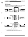
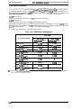
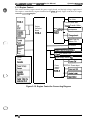
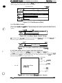
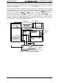
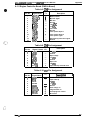
1.4.2 SelecType Functions
This printer has two levels of SelecType, Level 1 and Level 2. Either level can be selected by
pressing the Level 1 or Level 2 button. SelecType Level 1 is called Mode Configuration. SelecType
Level 2 is called Printer Configuration.
The following menu maps show the possible menus options in SelecType.
Key:
( ) - Only available with option.
[ ] - Only available with LJ-3/P/Si mode.
SelecType Level 1
1“’”’ T {;;:’
PAGE SIZE
MON
C10
DL
C5
F4
EXE
GLG
GLT
LGL
A4
A5
B5
LT
HLT
1 - 999
COPIES
ORIENT .
FONT
STATUS SHEET
FONT SAMPLE
SUB CONFIG .
SYSTEM CONFIG .
Refer to mode menu map
Refer to mode menu map
Refer to mode menu map.
O to 62
FULL PRINT
-64 to 63
T-OFFSET
-64 to 63
L-OFFSET
available bytes
MEMORY LEFT XX
o to 4
LOAD MACRO
1 to 4
SAVE MACRO
1 to 4
DELETE MACRO
I PowerOn MACRO
0 to 4
Figure 1-5. SelecType Level 1 Menu Map
SelecType Level 1 in LJ-2P and 3/P/Si Mode
\
c“
i
ORIE”
x Fi! i!k
—
font number —
font number —
‘o”’ n;“–
— font number —
SUB CONFIG .
0 to 128 LINES
E ~~~E’—
Roman-8
IBM-US
IBM-DN
ECM94 -1
IRV
French
UK
Chinese
ANSI AS
Norwegl
Swedish
Norweg2
. . .. .
c)
Swedis2
French2
JIS ASC
IBM Por
Italian
IBM Spa
Portugu
HP Germ
Spanish
HP Span
German
[PITCH or HEIGHT]
[PITCH or HEIGHT]
[PITCH or HEIGHT]
Roman E
Legal
PcMult i
[ PcPortu]
[ PcUSA]
t PcNordi ]
[ PcCanFr]
[ PcMath]
IVelnter]
[ PcText ]
[Ve US]
[Windows ]
[ PcPubli ]
[VeMath]
I DeskTop ]
[Math-8 ]
IPiFont ]
[VeZapfD]
[ PsZapfD]
IZd1001
[Zd200 ]
[zd300 ]
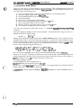
Figure 1-6. SelecType Level 1 in LJ-2P & 3/P/Si Menu Map
Rev. A
1-21
EPL-5000/5200/Action Laser 1000/1500 Service Manual
General Description
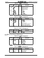
SelecType Level 1 in Epson GIJ2 Mode
ORIENT .
FONT
SUB CONFIG . ~
I
I
I
Not shown
Not shown
LJ3 -GL12
GL - 1 ike
PORT
ORIEm. ~ “NO
OFF
‘c”’ ~ AO, Al, A2, A3, A4 or AL — A4, A5, B5,
“L.
~
LT, HLT, ‘G’,
GLT, GLG, EXE,
F4, MON, C1O,
DL, C5
CORNER
CENTER
0/1
0.05 to 5.oomm
BUTT
SQUARE
TRIANGLE
ROUND
MITER
JOIN
M/B
TRIANGLE
ROUND
BEVEL
z NONE
OFF
‘mOEJEcT ~ 10 to 60
Figure 1-7. SelecType Level 1 in EpsonGL/2Mode Menu Map
SelecType Level 1 in LQ and FX Mode
O’l’”’. ~
‘0”SUB CONFIG .
PORT
LAND
Courier
Prestige
(ocR-B)
(ocR-A)
DL
““z
CONDENSED
L-MARGIN
R-MARGIN
T-MARGIN
TEXT
SKIPBOTTOM
CGTABLE
10
12
15
Prop.
ON/OFF
O to available
O to available
0.50 to 1.50
1 to available
ON/OFF
ITALIC
Pc USA
PcMult
PcPort
COUNTRY
1=
I
USA
France
German
UK
Denmark
Swden
Italy
ON/OFF
J-REPRINT
ON/OFF
AUTO CR
two types
ZERO CHAR.
ON/OFF
WIDE PAGE
~ DARK
—B-IMAGE
—
k
PcCanF
PcNord
DLoad
Spainl
Japan
Norway
Demk2
Spain2
LatinA
LIGHT
BCODE
Figure l-8. SelecType Levell in LQandFXMode Menu Map
1-22
Rev.A
EPL-5001U5200/Action Laser 100W15OO Service Manual
Genetadhacription
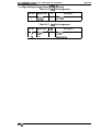
SelecType Level 2
FEATURE PRINT
EPL-5000/Action Laser 1000
EMULATION/CH X
P
LJ-2P (PSSILJ-2P)
EPL-5200/Action Laser 1500
3/P/Si (PS&3/P/Si)
s
(3/P/Si) (PS&3/P/Si)
LQ (PS&LQ)
LQ (PS&LQ)
FX (PS&FX)
FX (PS&FX)
(EpsON GL)
(EPsON GL)
(Ps)
(Ps)
T (EpsON GL2)(pS&GL2)
EPSON GL2 (PS&GL2)
CH P CONFIG I/F.
INTERFACE
PARALLEL
+ ~~;;::A~
T CH S CONFIG I/F
WORD LENGTH
BAUDRATE
PARITY
STOP BIT
mode
1 (0)
,,
RX-BUFFER SIZE
-..
!%&XOFF
ENQ/ACK
DSR
CTS
X K
P —
s— XK
T (o)-
‘ S E R ~ ;::;;!;L
10 to 600
CH TIMEOUT
ON/OFF
AUTO CONT.
P, s, o
“G-T!!!!g!!:
‘“S1TY7 F:*;
NEW
TONER
E*****F
E**** F
E.*. F
E**
F
T
LIFE 5000 to 9000
‘ERs’oN T ;&~F
PAGE
COUNTER
‘lTech - ?;$
‘T”DBY ~ :;:;:E
Figure 1-9. SelecType Level 2
Note:
Rev. B
The Action Laser 1000 does not indicate CH S (serial interface).
The standatd EPL-5000ZAction Laser 1000 does not have R/Tech.
1-23
EPL&OOO/5200/Action Laser 1000/1500 Service Manuai
General Description
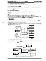
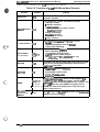
1.4.3
Display of Messages
This printer displays three types of messages on the LCD: status messages, error messages, and
power on messages.
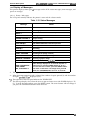
1.4.3.1 Status Messages
The LCD panel normally indicates the printer’s status and the software mode.
Table 1-15. Status Messages
Status
Message
READY ● 1
Normal condition
WARMING UP *3
Warming up
DATA *1
Data has been received while the printer is off line
PRINTING *2
Printing
PAPER FEEDING *2
Paper feeding
PRINT PAUSED *2
Print paused
COPY END ● 2
The COPY END button has been pressed
STANDBY *1
Standby mode
RESET ● 1
Resetting
INITIALIZE
Initializing
FONT CREATING
Creating fonts (image creation)
CHAR CREATING
Creating characters by caching
GRAPHIC DRAWING
Drawing a graphic image
OFF LINE ● 4
Off line with no data in the buffer
NEW CARTRIDGE?
YES, RESET
NO, CONTINUE *4
This message displays for 10 seconds at power on
when toner is out (the TONER display is “E* F“).
To reset the toner counter, press the RESET button.
The toner counter does not change when you hold
down the CONTINUE button for over 10 seconds.
*1: The right side of the LCD panel indicates the charnel and software mode.
*2: When the multicopy print mode is selected, the number of copies printed (X) and the number
of copies specified-(Yiare displayed (X/Y).
*3: The right side of the LCD panel indicates the TONER LEFT.
*4: This message displays also, when the cover is open and toner is out (the TONER display is “E*
F“). To reset the toner counter, press the RESET button. The toner counter will not change if
you press the CONTINUE button or close the cover.
1-24
Rev. A
Genem/Description
EPL&@W52t?U/Actkm hser llWW1500 Servke MZmual
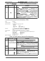
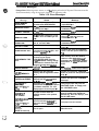
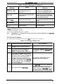
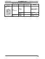
1.4.3.2 Error
Messages
If any of the following errors occurs, it will be displayed on the LCD panel. The error must be
cleared immediately using the measures shown in the following table.
Table 1-16. Error Messages
Status
Measures
EEPROM capacity is insufficient to
accommodate SAVE MACRO.
Delete unnecessary MACRO and ther
repeat SAVE. ● 3
The IC card was removed while the
FEED light was M. ● 1
The IC card in slot #X is not
accessible. ● 1
An IC card was inserted in on line
mode or while the FEED light was
M. ● 1
The total capacity of the card in
slot A exceeds 4MB.
Full print mode is recommended. ● 1
.2
Reinsert the IC oard and press the
CONTINUE button.
Remove the IC osrd and press the
CONTINUE button.
Message
SAVE MEMORY
OVERFLOW
RESIDENT CARD
ILLEGAL CARD #X
REMOVE CARD
CARD MEMORY
OVERFLOW
SET FULL PRINT
PAGE BUFFER FULL
Text data has filled the buffer, and
the page is ejeoted. ● 1 ● 2
A memory shortage caused by:
1) Printer mode change.
ADD MEMORY FOR
CH X
INVALID ASSIGN
INSUFF. MEMORY
PAPER SIZE ERROR
rmy sm xxx
paper size)
xx is OPT, STD, or
UJTO
>ApER O(JT
2) RX-BUFFER SIZE increase.
3) CH INDIVIDUAL setting change.
X indicates the channel where the
memory shortage was deteoted.
PostSoriptT” mode is set to Iwo
channels.
Register-type data filled the
memory, and the registration failed.
● 1 *2
The printer’s paper size was
different from the sekoted paper
size. ● 1 ● 2
The paper in the seleoted tray is
different from the paper size chosen
by software command. The LCD
displays pape r size and tray. ● 1 ● 2
No paper is left in either the
standard cassette or the optional
cassette.
>ApER OUT )(x)(
No paper is available in the
paper size)
xx is OPT, STD, or
specified cassette. Indioates the
paper size and the oassette to be
LJTO
:OVER OPEN
[XXX)(XX
XXXXX is toner left)
loaded.
Cover is open.
Remove IC card and press the
CONTINUE button. ● 3
Remove the IC oard and press the
CONTINUE button.
Confirm and press the CONTINUE
button. ● 3
Confirm and press the CONTINUE
button. And add optional RAM chips.
‘3
Add memory. Press the LEVEL 2
button to enter SelecType Level 2,
and adjust the INDIVIDUAL memory
distribution, or reduoe RX-BUFFER
SIZE.
Set PostSonpt” mode to one channel.
Confirm and press the CONTINUE
button or power off. Add optional RAM
chips. ● 3
Confirm and press the CONTINUE
button. ● 3
Load proper paper and press the
CONTINUE button, or simply press
the CONTINUE button.
PRESS ON LINE is dispfayed, when
paper is loaded in the standard or
optional tray. After this displays, press
the ON LINE button.
Load paper into the cassette.
Close the cover.
/:’...
L)
Rev. A
1-25
EPL-5000/5200/Action Laser 100011500 Service Manual
General Description
Table 1-16. Error Messages (Continued)
Status
Message
Measures
PAPER JAM
A paper jam has occurred.
SPL IGNORED
The mode was not changed by EJL
or PJL. *1 *2
Connect the optional lower cassette,
and press the CONTINUE button.
Or press the CONTINUE button. *3
Remove the jammed paper.
Afterward, press the CONTINUE
button. (System recovery is always
performed automatically.)
Open the cover and remove the
jammed paper. Afterward, close the
cover.
Confirm and press the CONTINUE
button.
Printer problem.
Service required.
RESELECT TRAY
A paper jam has occurred in the
feed process. *1
—
FEED JAM
SERVICE REQ.
Xxxxx
The optional lower cassette has
been selected, but it’s not
connected. *1
*1: The CONTINUE light flashes.
*2: AUTO CONTINUE is possible.
*3: Pressing the RESET button also is possible.
Note:
“WARMING UP” is displayed to give the printer time to clean the OPC after error recovety
measures are taken.
1.4.3.3 Power On Display
The control panel will display the messages in the table below only at power on.
Table 1-17. Display at Power On
Order
Error Operation
Control Panel Display and Operation
1
All lights light up for approximately 1.5
seconds.
—
2
The system checks the EPROM and
MASK ROM. The message “ROM
CHECK” is displayed on the LCD panel.
The message “SERVICE REQ. Cxxxx” will
be displayed if an error is deteoted during
the cheek.
3
The system cheeks RAM. The message
“RAM CHECK X.X MB” is displayed on the
LCD panel, and the capacity of RAM that
has passed the check is displayed as
“X. XMB”. All lights go off. This message
remains on the LCD for several seoonds
after the check has been completed. Then
a normal message, such as “WARMING
UP,” will be displayed.
The message “RAM ERROR” will be
displayed if an error is detected.
The system checks the EEPROM.
If an EEPROM error occurs, “START UP
ERROR LT c> A4° will be displayed after
the RAM check. When the “>” or ‘<”
button is pressed, the EEPROM is reset to
the factory setting. The message “WAIT”
is displayed during the resetting operation.
4
1-26
Rev. A
GeneralDeacnjWbn
EPL4WO0/5200/Actkm Laaer lfXW15tU.1 Samba Manual
1.4.4 Printer Sharing
This printer has two methods of printer sharing. This section describes printer sharing and the data
receive buffer.
1.4.4.1 Individual Mode
It is possible, depending on the RAM partition method, to allocate the various modes to either CH
P, CH S, or CH O. The partitioned R4M segments do not interfere with each other, so the user of
each channel can share the printer as if there were actually three individual printers.
Mode Assign
\
Channel P
Parallel
User 1
4
mode
4
Mode Assign
\
User 2
—
Channel S
RS-232C
+
mode
...
[’‘
.. ;
Mode Assign
4
User 3
User Memory
for Channel O
Channel O
Option
1
mode
I
Figure 1-10. Individual Made
Note:
The ActionLaser 1000 does not have a serial interface.
PostScript mode &m be assigned to only one channel of the three (or two).
-, .
,c)
Rev. A
1-27
EPL-5000/5200/Action Laser 1000/1500 Service Manual
General Description
1.4.4.2 Auto Sense Mode
It is Possible to allocate each mode to CH P, CH S, or CH O. The entire user memory will be
allocated to the channels that are used. The channel that receives the data first will print first.
Mode Assign
User 1
—
Channel P
Parallel
b
b
mode
\
\
\,
\
Mode Assign
User 2
—
All
User Memory
Channel S
RS-232C
mode
/
Mode Assign
●
User 3
Channel O
Option
mode
Figure 1-11. Auto Sense Mode
Note:
The ActionLaser 1000 does not have a serial interface.
1.4.4.3 Data Receive Buffer
The size of the data receive buffer for each interface (parallel, serial, and optional) can be assigned
separately through Sela ‘ype.
1
I
“’””e” ~ ‘AMP
C’ann’ls
Channel O
~
I
““s
I
RAM O
Figure 1-12. Receive Buffer Allocation
1-28
Rev. A
EPL60i?Q/521W/Action Laser l@W75tW Service Manual
1.4.5
Geneml Description
Controller RAM Status
This printer allocates the controller RAM to increase efficiency. The remaining RAM size can be
shown using the MEMORY LEFT function in SelecType Level 1. The usable RAM size depends on
user operation in the following cases:
1) The size of received data (except in optional EPSON CL and PostScript modes).
2) The FULL PRINT setting made in SelecType.
3) The RX-BUFFER SIZE setting made in SelecType.
4) Font downloading.
5) Bit-image (or raster graphics) downloading.
6) Form overlay registration/deletion (for optional GQ mode).
7) Macro registration/deletion (for HP mode).
8) Business graphics registration/deletion (for optional GQ mode).
9) The number of simultaneously used interfaces.
. , t. Dy
.- . mumpymg
. . ., . . . . - ,1X”.
can
De *esumareo
INL–Dy 8LIn 1), the size of memory used by the amount of data
“N”
‘.
to 20 bytes.
In 2), the amount of memory used can be calculated, as described below, using the value “n’*
defined for the FULL PRINT setting.
20 KB x n
,-.
(’. .. ‘
(0< n < 62)
Settings that exceed the ranges shown below waste memory capacity. The system goes into
full-page buffer mode if any of the following maximum “n” values is reached. (Printing is done
after the complete image for the page has been developed in RAM.) However, the “n” value should
be set to the minimum necessary value. It is recommended that there be a total of 15MB or more
memory when using the full page buffer mode.
A4: n < 51,A5: n <35, B5: n S 43, LT: n 547, LG: ns 62
GLT: n <45
GLG: n <57,
HI-T: n <36, EXE: n <45,
MON: ns 31, ~: n <38, D : n <37
F4: ns 57, C1O: n <41,
In 3), the amount of memory used is the size of the RX-BUFFER SIZE setting in SelecType.
However, in 6) and 7), a memory overflow may occur when the job is executed (printed) even
though registration is possible. (This is because the amount of memory necessary for execution is
approx. 8 to 20 bytes.) In 8), all the allocated memory will be used.
If a memory shortage occurs:
PAGE BUFFER FULL will be displayed for 1).
INSUFF. MEMORY will be displayed for 4) though 8).
For 2) and 3), setting SelecType will not be possible. It is suggested that you change the FULL
PRINT setting if SET FULL PRINT is displayed.
It is necessaxy to install optional memory if INSUFF. MEMORY or PAGE BUFFER FULL is
displayed.
Rev. A
1-29
EPL-5000/5200/Action Laser 1000/1500 Service Manual
General Description
1.4.6 Optional Memory
If you have difficulty printing complex, graphics-intensive pages of if you regularly use
downloaded fonts, you may need to install the optional rnernory (RAM) chip sets on this printer’s
controller board. The printer’s controller board comes with either 0.5MB of RAM installed (for the
EPL-5000/ActionLaser 1000) or l..0MB of RAM installed (for EPL-520Q/ActionLaser 1500). Two
types of RAM chip sets are available.
0.5MB RAM chip set
Each set contains four 256K bit x 4,80 ns, DRAM 20-pin DIP chips
2.OMB RAM chip set
Each set contains four 1 Mbit x 4,80 ns, DRAM 20-pin DIP chips
By installing RAM chip sets, you can increase the printer’s memory to a total of 6.5MB (for the
EPL-5000/ActionLaser 1000) or 5.OMB (for EPL-5200/ActionLaser 1500), including the resident
memory.
The table below describes the RAM chip combinations.
Table 1-18. RAM Chip Combinations
I
Chip Set Installed
*
1-30
Total RAM
EPL-5000
ActionLaser 1000
EPL-5200
ActionLaser 1500
No chip sets
0.5MB
1.OMB
One 0.5MB chip set
1.OMB
1 .5MB
Two 0.5MB chip sets
1 .5MB
2,0MB
Three 0.5MB chirI sets
2.OMB
●
One 2.OMB chip set
I
One 2.OMB chip set
One 0.5MB chiD set
One 2.OMB chip set
Two 0.5MB chip sets
I
I
Two 2.OMB chi~ sets
I
2.5MB
3.OMB
3.5MB
4.5MB
I
I
I
I
3.OMB
3.5MB
*
5.OMB
Two 2.OMB chip sets
One 0.5MB chip set
5.OMB
*
Three 2.OMB chip sets
6.5MB
*
On the EPL-5200/ActionLaser 1500, one 0.5 MB chip set is initially installed, so you can add
only two more optional chip sets.
Rev. A
EPL400@5200/Action
Laser 100W15OO Service Manuai
GeneraiDascription
1.4.7 Emulation Mode Switch Function
This section describes the emulation mode switch function.
1.4.7.1 Emulation Switch by SPL
The three types of emulation switch functions described below are available on this printer. They
are referred to as SPL (Shared Printer Language).
EJL: EPSON Job Language
This is Epson’s original language system. It is able to skip among various destinations, as shown in
Figure 1-13.
PJL: Printer Job Language
This is HP’s original language, which is available with the LaserJet” IIISi printer.
It is able to move only among PS, PCL, and EJL. Other modes are able to entry to PJL only. The
precise specifications for this language are ba@ on the HP LaserJet@ IIISi.
ES: Emuiation Switch
This is a method offered from Adobe, which is able to switch between PostScript” and PCL. The
precise specifications are based on software from Adobe.
.,.—
The figure below shows three types of mode switching.
Neither EJL nor PJL switches the mode directly. They first exit.the current mode and return to EJL
or PJL. Then they enter another mode.
F)(
ES
LO
v
Ps
A
GQ
ES
EPSON GL
I
I
I
I
Figure 1-13. Emulation Switch by SPL
1.4.7.2 Intelligent Emulation Switch
The Intelligent Emulation Switch (ES) automatically switches the emulation switch mode,
depending on the data sent fiwom thehostcomputer through one of the interface channels. It is able
to switch between PostScript and other modes as shown in the figure below.
LQ
U-2P
3/@i
Postscript
PS&G12
Fx
Figure 1-14. Intelligent Emulation Switch
Rev. B
1-31
General Description
1.4.8 Resolution
EPL-5000/5200/Action Laser 1000/1500 Service Manual
Improvement Technology
The EPL-5200/ActionLaser 1500 and the EPL-5000/ActionLaser 1000 with the optional Epson
PCL5/RITech Upgrade board have RITech (Resolution Improvement Technology), which is
desibmed to improve print quality. By this metiod, the dot map data extracted from the image data
is reassembled to improve print data.
The main improvement of this technique is in eliminating “jaggies” in diagonal lines. Also, it is
most effective when the dot map data fits the development characteristics of the printer mechanism
well. It is therefore necessary to set appropriate values in SelecType mode.
--+\/
>
m/
A-
Figure 1-15. Effect of RITech
Note:
R/Tech is not as effective forprinting a mesh pattern or gray scale. In such cases,
R/Tech must beset to OFF. (The default setting is MEDIUM.) Since the R/Tech effect
depends on the toner condition, it .shouldbe adjusted when the imaging cartridge k
replaced or after the imaging cartridge is used for a long time.
The following settings are available in SelecType Level 2 for RITech: HEAVY, MEDIUM, LIGHT,
OFF. When the toner density of area A is almost the same as that of area B (as shown in the figure
below), it is the optimum setting. In other words, the optimum. setting is achieved when it is
difficult to distinguish the shape of area A from that of B.
Figure 1-16. RITech Adjustment
1-32
Rev. A
EPL-500W5200/Action Laser 100W75OO Service Manual
General LMscrfptbn
1.4.9 EEPROM Reset
@
EEPROM reset operations are only required when the main board replacement, EEPROM
replacement, or firmware version is revised, and these operations are specified in the accompanying documentation.
■ EEPROM memory reset (excluding clearing of the page counter and toner counter)
Turn on the power while pressing the ON LINE, FEED, and CONTINUE buttons
simultaneously, the printer enters EEPROM clear mode, and the message STARTUP ERROR is
displayed on the LCD. Press the left or right cursor button (default paper size selection, A4 or
letter). All settings stored in EEPROM are replaced with the factory default settings, except the
page counter and the value for toner left in the imaging cartridge.
■ EEPROM memory all clear (including clearing of the page counter and toner counter)
Turn on the power while pressing the ON LINE, FEED, and CONTINUE buttons
simultamwusly. Afterward, both the page counter and toner counter can be cleared by
pressing either the left or right cursor button and holding down the CONTINUE button, while
the message START UP ERROR is displayed on the LCD.
Note:
.....
(%, i
(’,
This printer’s STATUS SHEET is changed to EPL-5200/Action Laser 1500, while set the
optional PCLSRITech Upgrade Board and EEPROM memory all clear.
Geneml Description
EPL-5000/521W/Action Laser 10011t1500 Servioe Manual
1.5 MAIN COMPONENTS
To simplify maintenance and repair, the main components of the EPL-WOO/EPL-52tXl/ActionLaser
1000/ActionLaser 1500 have been designed for easy removal and replacement. The main
components are:
c1
C108 MAIN Board
c1
Q
Control Panel
PWB-A Board
Engine controller circuit board
PWB-E Board
Power supply circuit board
PWB-F Board
High voltage supply circuit board
PRINTHEAD UNIT
Optical unit
FUSING UNIT
Drive Unit
Imaging Cartridge
Housing
Lower Paper Cassette Unit (optional)
Face-up Output Tray (optional)
u C82907° ROM-B Board
u
u
LI
a
c1
c1
c1
c1
c1
Videqcontroller circuit board
PCL5@ program and fonts ROM board
c., , : -j
Face-up Output Tray
/
. FUSING UNIT
PWB-E Board
PWB-F Board
PRINTHEAD UNIT
PWB-A Board
C82907*
ROM-B Board
C108 MAIN Board
Figure 1-17. Component Layout
1-34
Rev. A
EPL&O(hM5200/Aciion Laser 1OOW5(M Servkx Manual
General Description
1.5.1 C108 MAIN Board
The C108 MAIN board is video controller board. The functions of this board main are receiving
print data from host, generating the print image (video), and sending the print image to the engine
controller via the video interface. A 16-bit 16.6i’ MHz CPU MCMOOO (location: IC2) is used, and
the following memory chips and custom ICS are assigned to the 16MB memory space.
■ Memory chips
8M-bit MASK ROM (1C5) or 8M-bit EPROM (lC5) or two 4M-bit EPROM (IC5,7)
4M-bit DRAM (ICY)
1 M-bit DRAM (1C31, 32,33, .34)
16K-bit EEPROM (IC8)
■ Custom [Cs
Standard cell E05A83 (IC4)
Gate array E05A84 (IC3)
9 Others
Serial interface driver/receiver
MAX238 (IC30)
E05A84 (IC3) 4M DRAM (iC9)
)
(IC6
MAX23
(IC30)
(.:.-,.::
.,
==J—77—~
IC Card Slot
EEPROM Type-B l/F
(IC8)
Connector
Figure 1-18. C108 MAIN Board
Rev. A
1-35
EPL-5000/5200/A ction Laser 1000/1500 Service Manual
General Description
There are four types of C108 MAIN boards used as after service parts. The following table shows
differences in them.
Table 1-19. Differences in Components for the C108 MAIN Board
I
Action Laser 1000
EPL-5000
EPL-5200
Action Laser 1500
1 M DRAMs
(directly soldered
to board)
1 M DRAMs
(Directly soldered
to board)
IC31 ,IC32,
IC33, IC34
IC sockets
IC sockets
Serial interface
connector
Mini screw type
connector
— .
~oconnector I M i n i screwtype
connector
IC6
IC socket
None
‘IC30
MAX238
None
E05A84BB or
E05A84BC
E05A84BB or
E05A84BC
IC3
I
IC socket
I
Inch screw type
connector
None
I MAX238
MAX238
E05A84BC
E05A84BC
1.5.2 C82907* ROM-B Board (PCL5/RITech Upgrade Board)
The C82907* ROM-B board has the PCL5@ ROM and RITech IC. The printer changes from PCL4°
to a PCL5@ printer with the RITe.ch enhancement, once this board is attached to connectors CN3
and CN4 on the C108 MAIN board. In the EPL-5200/ActionLaser 1500, this board is standard. In
the EPL-5000/ActionLaser 1000, this board is optional.
H Memory chips
8M-bit MASK ROM (IC3) or 8M-bit EPROM (IC3) or two 4M-bit EPROM (IC6,7)
64K SRAM (IC2)
■ Custom IC
E05A74 (IC1)
E05A74 (ICI)
,
.
.
\
d
\
(IC6)
~ (IC3) or (IC7)
/
/
/
64K SRAM
Figure 1-19. C82907*ROM-B Board
1-36
Rev. A
GenamlDascii@b
EPL-5iXXV52001Acthn Laser liWt.V15@ Sandca Manual
1.5.3 Control Panel
The control panel includes a 20 column x 1 row LCD panel, which provides many functions for the
printer (e.g., displaying error messages or printer operation status). There are four types ofcontrd
panels.
Sda TYPO
LEWL 1
INPuTTRAY
PAGE WE
COPIES
WKN7ATlC+4
FONT
STAt’LlSS+lEJ3
FONT S4MRE
SUE CONFIGURATION
F ULL P R I N T
C$FSET
IAKIw
LEVEL 2
F EATURE P RIN T
EMULATION
INTERFACE
RECJ3VE ELS+ER
uSER L400E
c+4nA4Eour
AUTO CONTINUE
L#2+WWE
DENSTIY
/&atm~ua.
1000
TONER FIEMAINLNG
W33Elcm
pAGE COUN7ER
STANOS.Y
,!=
d
E
o
ON LINE
S4etTW
LEVEL 1
LEvEL 2
WTIALUE
RESET
COPYEW
(ml
LEVEL 1
n
FEEO
CC+lllNUE
UTIAL8ZE
aEsfn
D
v
o
(WA
-w-
a
LINE
LEVEL 2
EMT
o
COPVENO
CONTINUE
A
v
0
FEEO
D
*
EPL-5000
Action Laser 1000
S*I.C Type
LEVEL 1
SUO
LEvEL 2
INPUP TRAY
PAOE 8!2S
C OPI E S
ORIENTATIO&
PONT
STATUS SHEET
FO NT SAM~E
CONFIGURATION
FILL PRINT
FEATURE PRINT
EMULATION
INTERFAcE
RECEIVE SUFFER
USER MOOE
CH TIME OUT
AuTO CQNTINUE
LANGuAGE
OENSITV
TONER REMAiP4&G
VERSION
OFFSET
MACRO
m~w.
1500
PAQE COUNTER
RrT*ctl
STANOBY
1
~~
1=
3
m
S*IOCTYP*
LEVEL 1
o
ON LINE
IX LINE
LEVEL 2
Ear
l-nALl.2E
o
P E E O
v
EVEL 1
LEVEL 2
mul=
CoPvw
E201
n
IxNllNus
n
B
‘*
EPL-5200
Action Laser 1500
Figure 1-20. Control Panel
Rev. A
1-37
EPL-5000/5200/Action Laser 1000/1500 Service Manual
General Description
1.5.4
PWB-A Board
This is the engine controller board. It consists of an M37451M4 8-bit CPU (including a MASK
ROM) and a gate array. The board controls laser seaming (the polygon mirror drive motor), image
synchronizah~on, lase~beam pulse width, and power.
I
--M3745’ M4
Figure 1-21. PWB-A Board
1.5.5 PWB-E Board
The PWB-E is the power supply board, which consists of a switching regulator circuit. It converts
the AC line voltage into +24 V and +5 VDC voltages. There are two types of power supply board,
the 100/120 V type and 220/240 V type. The difference between the two circuis is o~y in tie input
section.
Do not touch VRIE on PWB-E board. This volume is for factory setting only.
F2
1
1
F1
!m
V;E
Figure 1-22. PWB-E Board
1-38
Rev. A
EPL&XXV5200/Action
1.5.6
Lasar liXXV151Xl Servfoe Manual
GenemlDeacrlptiOn
PWB-F Board
The PWB-F is the high voltage supply circuit board. h converts the development bias, OK drum
charge bias, and image transfer bias.
Do not touch VRIF and VR2F on the PWB-F board. These volumes are for factory setting
only.
n
o
VR2F
0
❑
Figure 1-23. PWB-F Board
1.5.7 PRINTHEAD UNIT
The printhead unit consists of the laser diode (semi-conductor laser), the scanner motor which
drives the polygon mirror for laser scanning, and several mirrors and lenses. ‘he laser beam
generated by the laser diode is conducted to the OPC drum surface by way of the polygon mirror,
as well as several mirrors and lenses, to create a latent electro-photographic image on the drum.
..
(“)
‘..+
.’
Figure 1-24. PRINTHEAD UNIT
Rev. A
1-39
EPL-51?OW5200/Ac fjon Laser 100W15OO Service Manual
General Description
1.5.8 FUSING UNIT
The fusing unit fixes the toner to the paper using heat and pressure. This unit has a heater lamp,
thermistor, and thermal fuse. There are two types of fusing units, the 120 V type and the 220/240 V
type. The difference between them is only the heater lamp.
Figure 1-25. FUSING UNIT
1.5.9 Drive Unit
The drive unit consists of the main motor and a series of gears and clutches. It drives the paper
transport rollers, OI?C drum, sleeve roller, fusing roller, and some other mechanisms.
Figure 1-26. Drive Unit
1.5.10 IMAGING CARTRIDGE
The core mechanisms of the printing process, such as chargin~ developing, and cleaning, are
integrated into this imaging cartridge.
Figure 1-27. IMAGING CARTRIDGE
1-40
Rev. A
EPL-5000/5200/Action Laser 1000/1500 Service Manual
General Description
1.5.11 Lower Paper Cassette
The optional lower paper cassette allows you to feed up to an additional 250 sheets of A4 or
letter-size paper into this printer.
Figure 1-28. Lower Paper Cassette
1.5.12 Face Up Output Tray
The face-up output tray is an optional tray useful for feeding single sheets of paper types, such as
envelopes, transparencies, labels, or heavy paper. The face up feeding method reduces curlirg and
the tray catches the paper at the paper ejection area at the top back of the printer.
Figure 1-29. Face Up Output Tray
Rev. A
1-41
Chapter 2
Principle Operating
Table of Contents
2-1
2.1 ENGINE OPERATION
2.1.1 Print Posses . . . . . . . . . . . . . . . . . . . . . . . . . . . . . . . . . . . . . . . . . . .. ....2-2
2.1.1.1 Paper Feeding . . . . . . . . . . . . . . . . . . . . . . . . ................2-3
21.12 Dram Charge .: . . . . . . . . . . . . . . . . . . . . . . . . . . . . . . . . . . . . . . .2-4
2.1.1.3 Laser Exposure . . . . . . . . . . . . . . . . . . . . . . . . . . .............2-5
2.1.1.4 Development .1 . . . . . . . . . . . . . . . . . . . .............---....2-5
2.1.1.5 Drum Cleaning . . . . . . . . . . . . . . . . . . . . . . . . . . . . . . . . . . . . -...2-5
2.1.1.6 Image Transfer . . . . . . . . . . . . . . . . . . . . . . . . . . . . . . . . . ......2-6
2.1.1.7 Fusing . . . . . . . . . . . . . . . . . . . . . . . . . . . . . . . . . . . . . . . . . . . . . .2-6
2.1.1.8 Paper Exit . . . . . . . . . . . . . . . . . . . . . . . . . . . . . . . . . . . . . .. ....2-6
2.1.2 Engine Control . . . . . . . . . . . . . . . . . . . . . . . . . . . . ... . . . . . . . . . . . . . . . 2 - 7
2.1:2.1 Main Motor Functionsand Control . .......................2-8
2.1.2.2 Paper Take-Up Sensorand PaperExit Sensor. . . . . . . . . .....2-10
2.1.2.3 Fuser Control . . . . . . . . . . . . . . . . . . . . . . . . . . . . . . . . . . . .....2-10
2.1.2.4 Scanner Mirror Motor Control . . . . . . . . . . . . . . . . . . . . . . .....2-11
2.1.2.5 LaserDiode Drive . . . . . . . . . . . . . . . . . . . . . . . . . . . . . . . . . . . .2-12
2.1.2.6 Bias Voltage and LaserDriveTiming . . . . . . . . . . . . . . . . .....2-13
2.1.2.7 Fan Motor Control . . . . . . . . . . . . . . . . . . . . . . . . . . . . . . . .....2-15
2.1.2.8 Power SupplyCircuit Function and Safety Protection . . . . .....2-15
2-16
2.2.1 C108MAlN Board0peration . . . . . . . . . . . . . . . . . . . . . . . . . . . . . . .. ..2-16
2.2 VIDEO CONTROLLER OPERATION
(“--.
2.2.1.1 Reset Circu~ . . . . . . . . . . . . . . . . . . . . . . . . . . . . . . . . . . . .....2-19
2.2.1.2 Bus Control Circuit . . . . . . . . . . . . . . . . . . . . . . . . . . . . . . . .. ...2-19
2.2.1.3 Interrupt Control . . . . . . . . . . . . . . . . . . . . . . . . . . . . . . . . . .....2-20
2.2.1.4 DRAM Management . . . . . . . . . . . . . . . . . . . . . . . . . . . . . .....2-20
2.2.1.5 Parallel Interface Circuit . . . . . . . . . . . . . . . . . . . . . . . . . . . .....2-21
2.2.1.6 RS-232C Circuit . . . . . . . . . . . . . . . . . . . . . . . . . . . . . . . . . .....2-21
2.2.1.7 Optional Type-B Interface . . . . . . . . . . . . . . . . . . . . . . . . . .....2-21
2.2.1.8 Video Interface . . . . . . . . . . . . . . . . . . . . . . . . . . . . . . . . . . .....2-22
2.2.2 C82907* ROM-B Board@era~on . . . . . . . . . . . . . . . . . . . . . . . . . .....2-22
List of Figures
Figure 2-1. Main Components . . . . . . . . . . . . . . . . . . . . . . . . . . . . . . . ........2-1
Figure 2-2. Print l%ocess Diagram . . . . . . . . . . . . . . . . . . . . . . . . . . . . . . .. ....2-2
Figure 2-3. Paper Feeding from the Multi-purpose Tray . ..................2-3
Figure 2-4. Paper Feeding from the Lower Paper Cassette . ...............2-4
Figure2-5. Drum Charge . . . . . . . . . . . . . . . . . . . . . . . . . . . . . . . . . . . ........2-4
.-. i
L
Figure 2-6. Laser Exposure . . . . . . . . . . . . . . . . . . . . . . . . . . . . . . . ..........2-5
Figure 2-7. Development . . . . . . . . . . . . . . . . . . . . . . . . . . . . . . . . . . . . . . . . . . .2-5
Figure 2-8. lmageTransfer . . . . . . . . . . . . . . . . . . . . . . . . . . ................2-6
Figure2-9. Fusing . . . . . . . . . . . . . . . . . . . . . . . . . . . . . . . . . . . . . . . ..-......2-6
Figure 2-10. Engine Controller Connecting Diagram . .....................2-7
F i g u r e 2 - 1 1 . Gearand RoUerPositions . . . . . . . . . . . . . . . . . . . . . . . . . . . . . . . . 2 - 8
Figure2-12. P/C Drive Section . . . . . . . . . . . . . . . . . . . . . . . . . . . . . . . . . . . ....2-8
Rev.A
2-i
Figure 2-13. Development Device Section . . . . . . . . . . . . . . . . . . . . . ........2-8
Figure2-14. Fusing Drive Section . . . . . . . . . . . . . . . . . . . . . . . . ............2-8
Figure 2-15. Feeding Drive Section. . . . . . . . . . . . . . . . . . . . . . .............2-8
Figure 2-16. Feeding Drive Section (option) . . . . . . . . . . . . . . . . . . . . . ......2-8
Figure 2-17. Main Motor Drive Circuit . . . . . . . . . . . . . . . . . . . . . . ...........2-9
Figure 2-18. Paper Take Up Sensor and Paper Exit Sensor On/off Timing. .. 2-10
Figure 2-19. Fuser Control Circuit . . . . . . . . . . . . . . . . . . . . . . . . . . . . . . .. ...2-10
Figure 2-20. Temperature for Fuser Control procedure . . . . . . . . . . . . . .....2-11
Figure 2-21. Scanner Motor Control Circuit . . . . . . . . . . . . . . . . . . . . . .....2-11
Figure 2-22. Scanner Motor Driving Start Timing . . . . . . . . . . . . . . . . . . .....2-11
Figure 2-23. Laser Diode Drive Circuit . . . . . . . . . . . . . . . . . . . . . . . . . . . . . . 2-12
Figure 2-24. /L DATA Generation Circuit . . . . . . . . . . . . . . . . . . . . . . . . .....2-12
Figure 2-25. Laser Emission Power AdjustmentTiming . . . . . . . . . . . . . .....2-12
Figure2-26. Laser Diode Error Detection . . . . . . . . . . . . . . . . . . . . . . . . . . . . .2-13
Figure 2-27. High Voltage Supply Block Diagram . . . . . . . . . . . . . . . . . . . . . . . 2-13
Figure 2-28. Print Process . . . . . . . . . . . . . . . . . . . . . . . . . . . . . . . . . . . . .. ...2-14
Figure2-29. PowerOn Sequence . . . . . . . . . . . . . . . . . . . . . . . . . . . . . . .....2-14
Figure 2-30. Print Sequence (Start) . . . . . . . . . . . . . . . . . . . . . . . . . . . . .....2-14
Figure 2-31. Print Sequence (End) . . . . . . . . . . . . . . . . . . . . . . . . . . . . . .....2-15
Figure2-32. Fan MotorSpeed Control Timing . . . . . . . . . . . . . . . . . . . . .....2-15
Figure 2-33. Fan Motor Malfunction Search Timing . . . . . . . . . . . . . . . . .....2-15
Figure 2-34. Power Supply Circuit Block Diagram . . . . . . . . . . . . . . . . . .....2-15
Figure 2-35. Video Controfler Section . . . . . . . . . . . . . . . . . . . . . . . . . . . . . . ..2-16
Figure 2-36. C108MAlN Board Block Diagram . . . . . . . . . . . . . . . . . . . . . ...2-16
Figure 2-37. Data Flow Diagram . . . . . . . . . . . . . . . . . . . . . . . . . . . . . . . .....2-18
Figure 2-38. Reset Circuit . . . . . . . . . . . . . . . . . . . . . . . . . . . . . . . . . . . . .....2-19
Figure 2-39. BusControl Circuit . . . . . . . . . . . . . . . . . . . . . . . . . . . . . . . .. ...2-19
Figure2-40. DRAM Management . . . . . . . . . . . . . . . . . . . . . . . . . . . . . . . . ...2-20
Figure 2-41. Parallel lnterface circuit . . . . . . . . . . . . . . . . . . . . . . . . . . . . . . ..2-21
Figure 2-42. RS-232C Circuit . . . . . . . . . . . . . . . . . . . . . . . . . . . . . . . . . .....2-21
Figure 2-43. C82907* ROM-B Board Block Diagram . . . . . . . . . . . . . . . .....2-22
List of Tables
Table2-l. Gears and Rollers . . . . . . . . . . . . . . . . . . . . . . . . . . . . . . . . . ......2-3
Table 2-2. Functions of C108 MAIN Board Main Elements . . . . . . . . . . .....2-17
Table 2-3. Functions of C82907* ROM-B Board . . . . . . . . . . . . . . . . . . . .....2-22
2-ii
Rev.A
EPL4i#WS200/Action
Opsrathg Pdnclphs
Lassr lfXXYISOO Sarvica Manual
2.1 ENGINE OPERATION
This section describes the functions and operating principles of the EPL-5000/5200, ActionLaser
1000/1500 engine.
Figure 2-1 shows the locations and names of the main engine components.
12345
6
7
8
9 10
11
12
13
14
15
16
17
18
19
20
21
29
1.
, “:>
(...
-T.
‘.
2.
3.
4.
5.
6.
7.
8.
9.
10.
11.
12.
13.
14.
15.
28
Paper tray
Paper guide
Printhead unit
Imaging cartridge
Upper lock release lever
Roller cover
Thermistor (THl)
Face-down exit roller
Upper fusing roller
Heater lamp (Hi)
Face-up/face down switching guide
Face-up tray (option)
Face-up exit roller
Fusing separator
Paper exit sensor (IW3)
27
26
16.
17.
18.
19.
20.
21.
22.
23.
24.
25.
26.
27.
28.
29.
25
24
23
22
Lower fusing roller
Fusing cleaning roller
cooling fan
Image transfer roller
Main motor (Ml)
Lower paper cassette (option)
Paper take-up sensor (PC2)
Transport roller
Transport roller (for option)
Paper take-up roller
Paper take-up roller (for option)
Paper cassette (for option)
Paper empty sensor (PC4) (for option)
Paper empty sensor (PCl)
Figure 2-1. Main Components
a\
Rev. A
2-1
EPL-5000/5200/Action Laser 1000/1500 Service Manual
Operating Principles
2.1.1 Print Process
This section describes the print process from paper feeding to paper exit.
Figure 2-2 shows a diagram of the print process.
8.
b
8.
Exit
(FID)
Exit *
(F/U)
d
+3
i’—-—-—-— -Fusing
6.
1,
7,
Exposure
‘L --- —. —. —-- ./”{
Imaging Cartridge
,—. — - — -—. —.!
1. ‘
Paper
Feeding
1
—.—.—-—-—-—-—-—-—-
1.
EEcl
Figure 2-2. Print Process Diagram
2-2
Rev. A
EPL+500W52001Action Laser lCXXV151M Sarvice Manual
Operating Pdncipks
2.1.1.1 Paper Feeding
There are two methods of feeding the paper into the printer. One is by using the multi-purpose
tray (standard tray), and the other is by using the optionaf 250-sheet lower paper cassette.
Paper-out conditions are detected by the paper empty sensor, located above the paper tray or the
cassette. While paper is in the tray or cassette, the detection lever for the paper empty sensor is
lifted. When the paper supply runs out, the detection lever is lowered, causing the shutter to
interrupt light from the LED to the photo-transistor. This causes the signal to go HIGH, informing
the engine driver that the paper tray or the cassette is empty.
When the paper take-up solenoid is actuated, the paper take-up roller rotates and feeds the first
page. The paper take-up roller stops after one rotation. Unlike the EPL-7000/7100/7500 and
EPL-8000/8100, which have a synchronizing roller, the EPL-5000/5200 and Actiorbser 1000/1500
have no synchronizing roller is installed. The timing to align the leading edge of the page with
image is detected by the paper take-up sensor.
When the page is on top of the paper take-up sensor, tie detection lever is lowered, allowing light
from the LED to reach the photo-transistor. This causes the signal to go HIGH, informing the
engine driver that paper has been detected.
The paper exit sensor
is located beyond the fusing roller in the paper path. When paper passes the
paper exit sensor, the detection lever is lowered, allowing light from the LED to reach the
photo-transistor. This causes the signaf to go HIGH, informing the engine driver that paper has
been delivered.
Multi-Purpose Tray (Standard Tray)
The paper guide can be moved to fit against the sides of various sizes of paper, allowing them to be
fed.
Although the paper take-up roller stops after one rotation, the transport rollers continue to feed the
first page, because these rollers are independent of the paper take-up roller. At this time, the
depression cam attached to the paper take-up roller depresses the paper lift-up plate to prevent the
feeding of a second sheet.
Lower Fusing Roller=
I
I
u
Figure 2-3. Paper Feeding from the Multi-Purpose Tray
Rev. A
2-3
Operating Principles
EPL-500015200/Action Laser 1000/1500 Service Manual
Lower Paper Cassette
of 250 sheets can be loaded in the 250-sheet lower paper cassette (option). The cassette
must be capable of handling the paper size, however. (The lower paper cassette unit can hold
letter, A4, or legal paper.)
A maxirnurn
The driving force for paper feeding and transport is from the transmission gear. All electrical
controls are performed on the printer side through the coupling connector.
Ca
Paper
e
Figure 2-4. Paper Feeding from the Lower Paper Cassette
2.1.1.2 Drum Charge
Drum charge is the process of charging the PC drum with static electricity before laser exposure.
This printer uses a brush charge method, rather than the corona charge method, to charge the
drum. In the brush charge method, there is no generation of ozone as a result of corona discharge.
This method also allows the drum to be charged at a low voltage, because a direct electric load is
applied to the PC drum.
Imaging
GND B
I
PC Drum
7+7
-300V
Cartridge
=0
c
to
-375V
D
A:
D r u m C h a r g e B i a s ~\~~#o~#;#~Bia5
C: Developing Bias
Figure 2-5. Drum Charge
2-4
Rev. A
Opwating Principiaa
EPL-5@W52001Actbn Laaar ltXXV15@ Sawice Manual
2.1.1.3 Laser Exposure
Laser exposure is the process of creating an invisible static electric image on the PC drum with laser
beams emitted from the printhead unit. The mirror motor (scanner motor) rotates the four-sided
mirror counterclockwise to produce a laser light scan. (One side of the mirror produces one scan.)
The SOS (start of scan) sensor detects the laser rays from the SOS mirror and outputs the SOS
signals to make the starting position of each line of the image uniform.
Laser em&on
JJm~
---- - Pcorum
Print Head Unii
Sos
u)
Appmx.
-Sov
~ po)ygon
Motor
‘
Invisible staticelactricity image
Figure 2-6. Laser Exposure
2.1.1.4 Development
Development is the process of creating a toner image on the PC drum by applying toner to the
invisible static electric image. The doctor blade spreads a thin, even coat of toner over the flexible
sleeve. When the toner passes between the doctor blade and the flexible sleeve, it becomes
negatively charged. The flexible sleeve transports toner to the surface of the PC drum and controls
the development with the developing bias voltage.
No positive toner is transported, and the doctor blade is charged to prevent printing from having a
foggy background.
~ Resin Sleeve
#
(’\
Doctor Biede~
PC Drum
+
@
+
PC Orum
●*
●*
Sleeve Roller
I
Figure 2-7. Development
2.1.1.5 Drum Cleaning
After the image is transferred onto paper, any remaining toner on the PC drum is scraped off by the
cleaning blade and collected in the used toner bottle.
Rev. A
2-5
EPL-500015200/Action Laser 1000/1500 Service Manual
Operating Principles
2.1.1.6 Image Transfer
Image transfer is the process of transferring the toner image created on the PC drum during the
developing process to the paper. This printer uses the roller image transfer method, instead of
corona image transfer, as the image transfer process. In roller image transfer, there is no generation
of ozone as there is with corona discharge. Also, there is no blurring caused by motion in the image
transfer, because the image transfer roller is maintained for the pressure bonding of the paper with
the PC drum.
A reverse bias voltage is applied so that the positive toner is not transferred onto the image transfer
roller. (The drum charge bias voltage is used.)
r PC
Drum
/
/
PC Drum
r Image Transfer Roller
Sequential Bias
Approx. 3.2KV
--@
Reverse Bias &
Approx. -0.8KV
J
\ image Transfer Roller
Figure 2-8. Image Transfer
2.1.1.7 Fusing
Fusing is the process of fixing the toner image transferred during the image transfer process onto
the paper. This printer uses the heating roller method for fusing. The heating roller method fixes
the toner image with an upper fusing roller that is heated by the heater lamp. The printer uses the
cleaning roller to clean that roller if it becomes dirty.
After power is turned on, the heater lamp lights up until the temperature of the upper fusing roller
reaches 165°C (329”F). After warm UP,. the mechanical control board controls the ON/OFF
operation of the heater lamp, based on the TH1 signals from the thermistor.
Thermal Fuse
TH1 Signals
Thermistor
Heater Lamp
Mechanical
Control
Board
A
Paper Guide
Low Voltage
/
Power Supply Board
Figure 2-9. Fusing
2.1.1.8 Paper Exit
The paper on which the toner image has been fused is fed to the face-down tray or the face-up tray.
2-a
Rev. A
Operating Pdncip/es
EPL-500i14i200/Actbn Laser 1UO(V1500 Service Manual
2.1.2 Engine Control
This section describes engine control, the power supply board, and the high voltage supply board.
The engine is controlled by engine controller board (PWB-A board). Figure 2-10 shows an engine
controller comecting diagram.
El-lCP
?
i Fan Motor
PWB-D
LO
Sos
Polygon
Scanner
motor
) Doctor Blade Bias
] Imaae Transfer Roller
Engine
Controller
Board
PWB-A
High vottage
‘1 Development
SuPPly B.
PWB-F
I
4
H=4
. Paper Take Up
Sensor PSI
m
Thermistor
Video
Controller
Board
C108
Main
t
E
Lower
Paper
Cassete
m
.,
(.
. .
Cassete
detecting
D
I
IL
Paper Take Up Solenoid SL1
i
~Paper Exit Sensor PS3
b
Paper Empty Sensor PE1
Power
supply
Board
PWB-E
1
I
I
1—4 AC Power Input
A
Paper Take Up
Solenoid SL2
bl
Figure 2-10. Engine Controller Connecting Diagram
Rev. A
2-7
EPL-5000/5200/Action Laser 1000/1500 Servioe Manual
Operating Principles
2.1.2.1 Main Motor Functions and Control
power from the main motor (Ml) drive is used for the P/C (photo conductor) drive, the developing
drive, the fusing drive, the standard paper slot feeding drive, and the lower paper cassette (option)
fe~ing Cirive. Figures 2-11 through 2-16 show the positions of the gears and rollers.
17
16
25
19
28
, ~lmage TrarKfer ROller
\
6
-
9
“ /
P/C Drum
Revolution
24.04 rpm
Process Speed
37.77 (mm/s)
/2
3< :-
.W
- -.
● 21
-—1-
1
● 26 ● 2S
.~ ● 54
Fig. 2-::&t~~: Drive
Fi .2-11. Gear and
F?oiler Positions
Fig. 2-13. Developing
Drive Section
FaCe Up, Exit Roller
Face Down 17
Exit Roller
1
~!
19
25
6-
16
● 2P \ ““-
Y
Transport Roller
+-f
~.
15
Upper Fusing Roller
Revolution
36.40 rfm
Process Sped
38.12 (rn~s)
14
n’ 2
.. —.8
1
Fig. 2-l:e~;:i:9 Drive
2-8
/
~ Paper Take-Up
Roller
l-t
+11
.—.
-. —..
1
@
L
1
1
Fig. 2-154::te&ng Drive Fig. 2-16. Feeding Drive
SectIon (Option)
Rev. A
Operating Principfas
EPL-500W5200/Action Lasar l&XY15tM Sarvfca Manual
Table 2-1. Gears and Rollers
No.
No. of Gear
Teeth
Roller Name
No.
No. of Gear
Teeth
Roller Name
15
36
i 16
54
24
17
15
4
14139
18
39/48
5
43
P/C Drum
19
15
6
30
P/C Drum
20
24/32
7
47
21*
14/24
8
29/41
22*
18
9
26
23*
18
10
23
24*
18
11
1 6/40
25*
16
12
46/69
Paper Take-Up Roller
26*
16
Paper Take-up Roller
13
23
Transpd Roller
27’
28
Transport Roller
14
l&75
28
14
Image Transfer Roller
Main Motor (Ml )
1
18
2
—-—
3
28/38/126 I
Sleeve Roller
Upper Fusing Roller
Face-Down Exit Roller
Face-Up Exit Roller
1
*Option (lower paper cassette)
Figure 2-17 shows the main motor drive circuit. The main motor (MI) is a four-phase stepping
motor. This motor is controlled by the CPU (ICIA) on the engine controller board (PWB-A). The
power supply board (PWB-E) has a stepping motor driver IC. This IC drives the main motor (Ml)
with a co”rkant current. The main mokr 7M1) is stoppd when the CPU (ICIA) on the engine
controller board (PWB-A) outputs TdA and TdB signals.
Power Supply Board
Engine Controller
Board PWB-A
PWB-E
CN2E
CN8A
A
B
TdA
TdB
4
3
2
1
8 CN3E
9
B 1
24V 2
10
11
B 4
A 5
24V 6
Main Motor Ml
3
/
A
Figure 2-17. Main Motor Drive Circuit
,.-.,.,
(J
Rev. A
2-9
EPL-500W5200 /Action Laser 1000/1500 Service Manual
Operating Principles
2.1.2.2 Paper Take-Up Sensor and Paper Exit Sensor
The DaDer take-up sensor has three functions:
~) L To detec; the top edge of paper. The engine starts printing when the detection signal
is received.
2) To detect paper size. The printer detects the time it takes for paper to pass the paper
take-up sensor during paper feeding. If this time is long, longer paper is feeding;
if the time is short, shorter paper is feeding.
3) To detect paper jams and feed jams.
If the paper take-up sensor does not turn on for paper feeding, the printer detects a feed jam. A
feed jam is a paper jam that has occurred in the feed process.
If any of the following conditions is detected, the printer detects a paper jam. A paper jam is a jam
that occurs in the printing process area.
●
●
The paper take-up sensor (PC2) or the paper exit sensor (PC3) is on at power on or when the
upper case is closed.
The paper take-up sensor (PC2) or the paper exit sensor (PC3) is not turned on/off within the
specified time. (Refer to the following timing chart.)
Take Up Solenoid ON
3.79 ,;
/,,
PC2{CN7A-2)
[sec.]
10.53
x
M
PC3(Ch16A-6)
Figure 2-18. Paper Take U Sensor and Paper Exit Sensor
On/8ff Timing
2.1.2.3 Fuser Control
The fuser is heated by the heater lamp, which is powered by AC voltage. When the power supply
board receives a FUSER LAMP signal from the engine controller board (PWB-A), the power supply
board (PWB-E) supplies the AC voltage to the heater lamp. This AC voltage is cut by the interlock
switch when the case is open.
The fuser temperature is detected by the thermistor. Based on the THl signals from the thermistor,
the engine controller board (PWB-A) controls the fusing temperature (165° C, 329” F) using the
FUSER LAMP signal.
Engine Controller
Board
(PWB-A)
CN11A
THERMISTOR
+5V
Fusing Unit
..................................
2
1
hermistor
Power
Supply
!
CN4E ,: ~
HEAT-L ‘i TF1
CN8A
FUSER LAMP
11
HEAT-N
3:
‘;
Figure 2-19. Fuser Control Circuit
2-1o
Heater
Lamp
I
~
~
!
OpWfngPrincip/es
EPL-51WW52001Actkan Lasar IWISOO Servica Manual
The following figure shows the fuser temperature control procedure.
Power On
[See ]
~1 ON
(CN6A-I f)
TH1(CN1
1A-1)
<
4.5V(2W degree C)
3.3V(165 degwe c)
2.2V(130 &gre2 C)
o.5v(55degrea c)
Figure 2-20. Temperature for Fuser Control Procedure
If the following conditions are detected, the printer indicates a fuser error (the LCD displays
SERVICE REQ. EOO03).
. The thermistor temperature does notreach55°C (131”F) within 15 sec.
The warm-up period does notend within 120 seconds.
The thermistor temperature drops to 130”C(266”F).
Thethermistortemperatureexceeds 200”C (392”F).
●
●
●
The thermo fuse (TFl) cuts power if the temperature of the fusing section rises to an abnormally
high level (over 200”C, 392”F).
2.1.2.4 Scanner Mirror Motor Control
Figure 2-21 is the scanner mirror motor (M2) control circuit. ‘l’he scanner mirror motor is driven
while the scanner motor receives the SCANNER MIRROR MOTOR (M2.ON) signal.
Engine Controller Board
PWB-AI
3canner Motor
CNSA
M2
5
+24V 4
GND2 3
POLYGON MOTOR
2
PORYGON LOCK
1
PORYGON CLOCK
Figure 2-21. Scanner Motor Control Circuit
Figure 2-22 is the scanner mirror motor driving timing chart. The scanner mirror motor rotates 0.15
seconds after the main motor (Ml) turns on. If the MIRROR MOTOR LOCK (M2:LOCK) signal is
not turned on within 3 seconds after the seamer mirror motor turns on, the printer indicates a
scanner mirror motor malfunction.
~ Main Motor On
[sec.]
M2:ON
(CN5A-3)
-..,
u
M2:LOCK
(CN5A-2)
<
~
3.0
I
>
Figure 2-22. Scanner Motor Driving Start Timing
Rev. A
2-11
EPLGOOO/5200/Action Laser 1000/1500 Service Manual
Operating Principles
2.1.2.5 Laser Diode Drive
Figure 2-23 shows the laser diode drive circuit. Laser diode emission is controlled by three signals
(L DATA, DA1, and DA2) from the engine controller board (PWB-A).
Laser Diode
——
S SCAN <
co ~
DA2
>
DAI
>
LD
Sos
(PWB-D)
L DATA
‘-k\ SOS Mirror
>
SOS sensor
Engine Controller
Board (PWB-A)
Figure 2-23. Laser Diode Drive Circuit
The L DATA signal is the laser ON/OFF signal. When it is LOW, the laser emits, and when it is
HIGH, laser stops emitting. L DATA is the combination of the two signals in the figure below. If
the VIDEO or the FORCED LASER DIODE ON signal is activated (LOW), the
L DATA signal will be active. The VIDEO signal is an image signal sent from the video controller
board (C108 MAIN board). The FORCED LASER DIODE ON signal is a laser emission signal to
apply the laser beam to the SOS sensor.
Forced Laser Diode ON
from
the Video Controller
m
Board (C108 MAIN Board)
~LDATA
Figure 2-24. /L DATA Generation Circuit
The laser diode is forcibly activated within between 0.2 seconds and 0.1 seconds after the scanner
mirror motor (M2) turns ON. At this time, laser emission power is adjusted. LDVR1 and LDVR2
are the laser emission power adjust signals; they are analog signals. LDVR1 is a tuning. LDVR2 is a
fine tuning.
....
kec.1
v Scanner Motor On
LDATA
(CN5A-7)
k
LDVR1
(CN5A-9)
LDVR2
(CN5A-1O)
LDLVL
(CN5A-11)
I
0.1 ,!,
0.2
>
I
::::
,,
: :
:
: : ;
: : :
Figure 2-25. Laser Emission Power Adjustment Timing
Operating Principbs
EPL-500W5200 /Action Laser 100W15OO Servke Manual
If the SSCAN si~al is not detected, the printer indica~ a laser diode malfunction. [f the scanner
nlirr{~r motor (M2) does not rotate, the printer also indicates a laser diode malfunction.
Scanner Motor On
LDATA
<
01
;
[sec.]
0.2
.
>
(CN5A-7)
SSCAN
(CN5A-12)
Figure 2-26. Laser Diode Error Detection
2.1.2.6 Bias Voltages and Laser Drive Timing
Figure 2-27 is a diagram of the drum charge bias voltage, image transfer bias voltage, doctor blade
bias voltage, and the developing bias voltage control circuit. These bias voltages are generated
from the +24 VDC from the high voltage supply board (PWB-F). If the printer detects a case open
condition, the interlock switch is set to OFF, which cuts the +24 VDC, which, in turn, cuts the bias
voltages.
These bias voltages are controlled by the engine controller board (PWB-A). The CH2QN (I-IV-T)
signal is the image transfer (roller) bias voltage control. While this signal is LOW, the image
transfer roller is charged to 3.2K VDC by the high vohage supply circuit. And while this signal is
HIGH, the image transfer roller is charged to --0.8K VW- The CHl:ON (Hv-C/T.R) si$# controls
the drum charge. While this signal is LOW, the PC drum is charged to -1.2K VDC.
The DB:CNT (HV-B.VR) signal is an analog signal for developing bias voltage control. lhis signal
controls the b“ias voltage l-wel (–300V to ~37;K VDC) using filog data. ‘The image densi~ is
controkd by the developing bias voltage level.
Engine Controller
Board
(PWB-A)
Inter Leek
+24 VDC
+24 VDC
:~ . . . . . . . . . . . . . . . . . . . . . . . . .
DB:CNT
CH2:ON
CH1:ON
Power Suppty
Board
(PWB-PU)
High Voltage Supply
Board
(PWB-F)
;
,
.
.
.
.
.
.
.
.
.
.
4 ~D•Œ:.
.
Image Transfer
- Bias (CH2)
3.2K or -0.8 K VDC
> Developing
Bias
-3oO to -374 VDC
.
.
L
j Drum Charge
-1.2 K VDC
Figure 2-27. High Voltage Supply Block Diagram
Rev. A
2-13
EPL-5000/5200/Action Laser 1000/1500 Service Manual
Operating Principles
Figure 2-28 is the print process, and Figure 2-29 is the power on sequence. During the power on
sequence (initialization), the printer detects mechanical errors.
Brush Charging
\
Laser Exposure
Development
Figure 2-28. Print Process
Power On
v
Fuser Temperature
130dgrae C
;
Polygon Motor
(M2)
0.8
165 degree C
[sec.]
i
1.61
>
Main Motor
(Ml)
; 0.5 i
Drum Charge
(CH1)
1.24
>
0.1 ,: :
Laser
Exposure (LD)
Development
(DB)
Image
Transfer (CH2)
Figure 2-29. Power On Sequence
Figure 2-30 is the start print sequence. The printer’s engine starts printing when the PRINT signal
is received from the video controller board.
Print
Drum
Charge (CHI)
0.5
Main Motor On
17
i 0.3 i
[sec.]
Laser
Exposure (LD)
Development
(DB)
Image
Transfer (CH2)
>
; 0.48 :
/,
; 0.62 j
1.27
2.32
.
; 0,36 ;
>
:
( - ) B i a s 1~
Figure 2-30. Print Sequence (Start)
2-14
Rev. A
Opwating Principles
EPL-50iXV5200/Action Laser 100WI5OO Service Manual
Figure 2-31 is the end of the print sequence. l’he printer stops the main motor (Ml) from rotatin&
when the paper exit sensor turns off after 2.53 seconds.
Main Motor Off
[Sec.] v
Paper Exit Sensor Off
Drum
1.27
Charge (CH1)
<
1.26
>
Laser
Expoaure (LO)
Development
(D%)
Imaga
Transfer (CH2)
Figure 2-31. Print Sequence (End)
2.1.2.7 Fan Motor Control
The fan motor (M3) rotates at all times after initialization of the engine has beerr completed. The fan
motor rotates faster during printing. When printing ends, the fan motor slows down after 15
seconds.
Print signal cm
Print er-d
[sec.]
FAM M.
(CN7A-9)
Figure 2-32. Fan Motor Speed Control Timing
1f the voltage of pin ICIA-64 on the engine controller board (PWB-A) does not exceed 150mV for 1
second, the printer indicates a fan motor malfunction.
pwer on
[Sec.]
17
FAM M.
(CN7A-9)
Figure 2-33. Fan Motor Malfunction Search Timing
2.1.2.8 Power Supply Circuit Function and Safety Protection
The printer’s power supply board (PWB-E) supplies the +5 VDC and +24 VDC. The
+24 VDC is used as the bias voltage supply, main motor (Ml) drive, seamer mirror motor (M2)
drive, fan motor (M3) drive, and solenoid drive. For safety protection, the +24 VDC line is cut
when the interlock switch (case open switch) is off.
Inter Lock
>- +24 VDC
~ ‘5 VDC
AC IN
–
Power Supply Board
(PWB-PU)
-------> SG
~ FG
Figure 2-34. Power Supply Circuit Block Diagram
Rev. A
2-15
EPL-5000/5200/Action Laser 1000/1500 Service Manual
Operating Principles
2.2 VIDEO CONTROLLER OPERATION
The video controller section generates the video signals for the received data. The video controller
section is separate in the C108 MAIN board, the C82907” ROM-B board (if installed), and the
control panel. The control panel is comected to the engine controller board (PWB-A), but is
controlled by the C108 MAIN board, which sends the signals for the control panel through the
engine controller board.
Video Controller
,..
. . - .
. -
.
- - - - -
.
Section
- - - - - - - - - - - - - - - - - - - - - - - - - - - - - - - - - - - - - - - - -
*
,
,
,
,
C82907*
ROM-B
Board
—
.
,
,
C108 MAIN Board
A
,*
El
.................................... t.....
●
●
●
*
*
,
,
*
,
*
:, Control
: Panel
Engine
Controller
Board
(PWB-A)
●
●
●
,
.
●
------------
.-!
Figure 2-35. Video Controller Section
2.2.1 CI08 MAIN Board Operation
Figure 2-36 shows a block diagram of the C108 MAIN board. The C108 MAIN board contains the
video controller, which consists of a 16-bit 68000 (16.67 MHz) CPU, the standard cells developed for
this printer, DRAMs, ROM, and a 16K-bit EEPROM.
HP Font
Cartridge
ICcard
CPU
68000
(IC2)
A
I
1
A I
.
T
E05A84
I
~
Option l/F
E05A83 (IC4)
I
Video
(IC3)
I
I
ADDRESS
DATA
CONTROL
> Video
I
qEEEcl
RS-232C
Parallel l/F
Figure 2-36. C108 MAIN Board Block Diagram
2-16
Rev. A
Operating Principles
EPL&OOLV5200 /Action Laser 100LV15OO Service Manual
Table 2-2 lists the functions of the C108 MAIN board main elements.
Table 2-2. Functions of C108 MAIN Board Main Elements
Location
Element
68000 CPU
IC2
Function
The CPU, which operates at 16.67 MHz, manages the video
controller operation.
This standard-cell contains the following functions:
Interrupt control
“ Address decoding
Clookcontrol
DRAM management (refresh control,
RAS/CAS oontrol)
Image processing
●
●
,C4
E05A83 standard
cell
●
●
RS-232C interface
Control panel control
s Video interface
●
●
. ...-,,,‘’
c
:e~A84‘tandard
IC3
This standard-cell mntains the folbwing functions:
Paralfel interface
●
●
●
DRAM management, with the E05A83
Video signal switching
This ROM stores the folbwing:
Basic Operating program
. HP emulation mode program
●
An 8M ROM or
IC5 or
IC5, IC7
two 4M ROMs
●
●
8M ROM
LQ/FX emulation mode program
Bit rnapfonts (the EPL-500W5200 has only
one 8M ROM.)
IC6
This ROM is the GQ chip option (GQ mode program and GQ
fonts) or the local language ROM (fonts) option (except in
ActionLaser 1000/1500).
IC8
This EEPROM stores the folbwing:
Model type
Printed page counter value
Toner life oountervalue
SelecType setting
●
EEPROM
●
●
●
DRAM
IC9, 31,32,
33,34, 10,
11, 12, 13,
~ 17, 16, 15, 14
The EPL-5000/ActionLaser 1000’s standard DRAM is IC9
(0.5MB) only; other DRAMs are options. The EPL-520W
ActionLaser 1500’s standard DRAMs are IC9, 31,32,33, and
34(1 .OMB total) only; other DRAMs are options. These
DRAMs are used as the working area of the CPU: input
buffer, image buffer, etc.
RS-232C
driver/receiver
MAX238
Rev. A
‘
I IC30
This IC changes the RS-232C signal level. (The ActionLaser
1000 does not have this IC.)
2-17
EPL-5000/5200/Action Laser 1000/1500 Service Manual
Operating Principles
Print data and commands transmitted from the host computer via parallel, serial, or optional
interfaces are read using the interrupt process of the CPU and stored in the DRAM input buffer.
The capacity of the input buffer can be specified by SelecType setting. A larger input buffer
improves the throughput.
Data and commands in the input buffer are processed by the CPU, which then stores the printing
bit map data (image data) in the V (video) -RAM (image buffer) in the DRAM. The size of the
V-RAM depends on the available DRAM size, and can be specified using SelecType. A page error
occurs when the V-RAM is so small that the CpU cannot process data faster than it is transmitted to
the engine controller board. If such MI error occurs, increase the V-RAM using SelecType.
The CPU transmits image data stored in the V-RAM in a temporary buffer in the SRAM, which is
located in an address space different from the CPU. The temporary buffer has a capacity equivalent
to several lines. This is controlled by the standard cell, which synchronizes and transmits the
temporary buffer’s data to the engine controller board.
Host
Computer
Host Computer
Parallel l/F Circuit
E05A84 (IC3)
-u
CPU
68000 (IC2)
-
Serial l/F
Circuit
E05A83 (IC4)
DRAM
Control
Circuit
r
ParalleW3erial
Converter
Engine
+ Controller
Board
Temporary Buffer ~
(SRAM)
Development
Q
I
I
,
t
>
Input Buffer :
v
I
~E!kl_2L
I
Page buffer)
Figure 2-37. Data Flow Diagram
2-18
Rev. A
Operating Principles
EPL@OW5200/Action Laser 100W15OO Service Manual
2.2.1.1 Reset Circuit
The 68C00 CPU contains the reset terminal, which is bidirectional and can initialize the system
either from inside or outside the CPU. The entire system (the CPU and the external devices) can be
initialized if both the HALT (CPU pin 20) signal and the RESET signal (CPU pin 21) are active
simultaneously. By executing a RESET instruction, a RESET pulse from inside the CPU can also be
issued to reset all the devices comected to the RESET line. This circuit uses an M51954A IC to
monitor the supply voltage and reset the CPU if a voltage level less than 4.25 V is detected. The
reset time is approximately 840 ms.
+5V
+5V
1-;
WCC
+5V
OUT
M51954AFP
(IC18)
c
+
74LS05
(ICIE)
f
Figure 2-38. Reset Circuit
2.2.1.2 Bus Control Circuit
The 68000 CPU outputs the R/W (read/write) signal, AS (address strobe) signal, and the FCO, FC1,
and FC2, signals (processor status) to the E05A83 standard celL The E05A83 standard cell uses
these signals to generate the RD (read strobe) signal, DTACK (wait control) signal, VPA (interrupt
control)signal, ~d BERR (bus error) signal.
>
AS
CPU
68000
(ic2)
<
<
<
i
>
FCO,l ,2
>
DTACK
E05A83
(IC4)
VPA
BERR
.+-”
Address
Data
Bus
Bus
‘D ‘
R
Figure 2-39. Bus Control Circuit
c1
Rev. A
2-19
EPL+5000/5200/Action Laser 1000/1500 Service Manual
Operating Principles
2.2.1.3 Interrupt Control
The E05A83 standard cell determines the priority level of the interrupt and outputs it to terminals
IPLO - IPL2. Then an interrupt is sent to the CPU. If the CPU accepts the interrupt, terminals FCO FC2 all go HIGH to indicate the interrupt acceptance to the E05A83 standard cell. The E05A83
standard cell confirms that terfinals FCO - FC2 are HIGH (interrupt acknowledge), and then sets
the VPA terminal to LOW and informs the CPU that this is an automatic vector interrupt. This
initializes the interrupt process. The E05A83 standard cell has a controller for the automatic vector
interrupt.
2.2.1.4 DRAM Management
The video controller uses DRAMs for the system RAM and for the V-RAM.
In the EPL-5000/ActionLaser 1000, a standard 256K x 16 DRAM is mounted in location IC9,
providing a total of 0.5MB. IC sockets IC31, 32, 33, 34, 10, 11, 12, 13, 17, 16, 15, 14 are optional
DRAM sockets. These IC sockets can use 64K x 4-bit DRAMs or
256K x 4-bit DRAMs.
In the EPL-5200/ActionLaser 1500, a standard 256K x 16-bit DRAM and four 64K x 4-bit DRAMs
are mounted in locations IC9, 31,32,33,34, which provide a total of 1.OMB. The IC sockets IC1O, 11,
12, 13, 17, 16, 15, 14 are optional DRAM sockets. These IC sockets can use 64K x 4-bit DRAMs or
256K x 4-bit DRAMs.
The DRAMs (including optional chips) are managed by the E05A83 and E05A84 standard cells.
The E05A83 standard cell handles the main management. The E05A83 outputs RAS/CAS, WE, and
OE signals. The IC9 DRAM is controlled directly by the E05A83. Other DRAMs (including
optional chips) are controlled by the CAS, WE, and OE signals from the E05A83, and also controlled
bv the RAS simal from the E05A84. The E05A84 changes the RAS output timing according to
DRAM size (@”Kx 4-bit DRAM or256K x4-bit DRAM). REFRSH
E05A83 (IC4)
RASEN
I
W E D a t a CASUCASU
OE Address
RASO
I
I
4+,
I
1“
4)
+
+
IC17
IC16
IC15
11
H
Iclo
ICI 1
IC12
t
IC14
I
L
3rd Block
M
T
I
Ti
IC13
I
,
2nd Block
IC9
I
IC32
I
1
IC33
I
, IC34
I1
I
1st Block
I
T
T
Figure 2-40. DRAM Management
E05A84
(IC3)
RAS1
RAS2
RAS3
Opsmting Principhs
EPL4iOOW52W/Action Lasar l@UV1500 Ssrvicx Manual
2.2.1.5 Parallel Interface Circuit
Figure 2-41 shows the parallel interface circuit block diagram. Data sent from the host computer is
latched within the E05A84 by the STROBE signal. The E05A84 outputs the BUSY signal
automatically to stop the host computer from sending additioml data. The CPU resets the BUSY
signal after reading the data from the E05A84, so that the printer is ready to receive more data from
the host computer.
DATA
STROBE
\ Latch
+
E05AS4
(IC3)
> .......
BUSY ~
......
Figure 2-41. Parallel Interface Circuit
2.2.1.6 RS-232C Circuit
This circuit uses the RS-232C receiver/driver IC MAX238 (IC30) to change the signal level from the
RS-232C signal level (-12 VDC or +12 VDC) to the ‘Ill signal leveI (O V or +5 V) or from the TTL
signal level to the RS-232C signal level. This IC converts +5 VDC to +12 VDC and -12 VDC.
The E05A83 standard cell changes serial @232C) data to parallel data. Since the Actionbser 1000
does not have an RS-232C comector, the CPU must check the maiel type for an RS-232C interface
at initialization. In a printer with an RS-232C interface, the R41N terminal (pin 16) for the MAX238
is pulled up to +5 VDC. The CPU checks the R40UT termina 1 (pin 20) for MAX238 at initialization.
If the R40UT termind is LOW, the CPU assumes that the printer is a model with no RS-232C. The
model with no built-in RS-232C (the ActionLaser 1000) can use a non-intelligent optional serial
interface (model C82305*/C82306*). This optional interface also uses the E05A83 standard cell as
the circuit to change serial data to parallel.
The models with a built-in serial interface (the EPL-5000/52~ and ActionLaser 1500) cannot use the
non-intelligent optional serial interface (model C82305*/C82306*).
3eriel
<- - - - - - - - - - - - - - G
Data
7
1--1
E05A83
(IC4)
Transmit
RS-232C
Interface
R41N
R401JT
(Ic30)
MAX238 Deted Signal ~
u
ca230s*/
Caz30a”
Serial
Interface
Figure 2-42. RS-232C Circuit
f .d
2.2.1.7 Optional Type-B Interface
This printer supports an Epson Type-B optional interface, which is controlled by the NH and BIF
signals from the E05A83 standard cell.
Rev. A
2-21
EPL-500tU5200/Action Laser 100WI5OO Service Manual
Operating Principles
2.2.1.8 Video
Interfaca
The E05A83 standard cell maps the SRAM into a memory space different from the system memory.
The CPU transmits data from the V-RAM (in the system RAM) to the SRAM using the E05A83
standard cell. The standard cell converts the image data in the SW from parallel to serial,
synchronizes it, and then transmits it to the engine controller board. In other words, the SRAM is a
temporary buffer used to transmit the image data to the engine controller board. This serial image
data is called the VIDEO signal of video interface.
The signal line of the internal video interface circuit (the C108 MAIN board and engine controller
board) can be broadly divided into four groups. The first group (PRINT, CPRDY, EPRDY, and
PRDY) gives the status of either the video controller or engine controller and indicates whether they
are ready to communicate with each other or ready to start the printing operation. The second
group (VSYNC) is the synchronizing signal for the printing operation. The third group (VIDEO) is
the serial video data signal. The fourth group (CMD, SRCLK, CTBSY, and ETBSY) is used to
transfer the coremands (from the video controller) or the status (from the engine controller) for
printer mechanism control.
This printer has RITech function optiomlly (EPL-50Q0/ActionLaser 1000) or standard (EPL-5200/
ActionLaser 1500). This function modifies the VIDEO signal with the E05A74 gate array on the
C82907 ROM-B board. If the C82907 ROM-B board is installed, the VIDEO signal travels through
the C8290P ROM-B board to engine controller board.
—
2.2.2 C82907* ROM-B Board Operation
The C8290P
ROM-B board has two functions: HP PCL/5 emulation and the RITech function. The
ROM stores the PCL/5 (EPSON GL/2) comman ds and fonts. The RITech function modifies the
VIDEO signal to smooth printed edges.
Table 2-3 lists the functions of the main elements of the C8290? ROM-B board.
Table 2-3. Functions of C82907* ROM-B Board
Location
Element
Function
E05A74
[cl
RITech IC
64K SRAM
IC2
Working area for E05A74
8M or
tWO 4M ROM
IC3 or
IC6, IC7
This ROM stores the following:
● PCU5 (EPSON GU2) mode
&alsble fonts for PCU5
sBit map fonts (Landscape)
From
C106
MAIN
8oaId
1
T
T
1
1
6M ROM
(IC4)
PAL16R4
(la)
(Not ussd)
(Not US8d)
rlrl
1~
SWIM
—
EOSA74
(IC2)
-
1
Addrsss
Data
8M ROM
(IC3)
or
TWO 4M ROM
(IC6,7)
> (lCl)
VIDEO
VIDEO
(RITsch)
r
1
<
Figure 2-43. C82907* ROM-B Board Block Diagram
2-22
Rev. B
Chapter 3
Disassembly and Assembly
Table of Contents
3.! GENERAL INFORMATION
3-1
3.1.1 Precautions for Disassembly/Assembly . . . . . . . . . . . . . . . . . . . . . ......3-1
3.1.2 TOOtS , . . . . . . . . . . . . . . . . . . . . . . . . . . . . . . . . . . . . . . . . . ............3-1
3.1.3 Small Parts . . . . . . . . . . . . . . . . . . . . . . . . . . . . . . . . . . . . . . . . . . . ......3-2
3.1.4 Service ChecksafterRepair . . . . . . . . . . . . . . . . . . . . . . . . . . . . . . ......3-3
. .. .
,’f. ,’‘
+,. -.
3.2 DISASSEMBLY AND ASSEMBLY
3-4
3.2.1 Removal ofthe Video Controller Section . .........................3-4
3.2.1.1 Video Controller Board (C108 MAIN) Removal . ..............3-4
3.2.1.2 PCL5/RITech Upgrade Board (C82907* ROM-B) Removal .. ...3-5
3.2.1.3 Control Panel Removal . . . . . . . . . . . . . . . . . . . . . ............3-5
3.2.2 Housing Removal . . . . . . . . . . . . . . . . . . . . . . . . . . . . . . . . . . . . . . . . . .. .3-6
3.2.2.1 Case Removal . . . . . . . . . . . . . . . . . . . . . . . . . . . . . . . . . . .. ....3-6
3.2.2.2 Rear Frame Removal . . . . . . . . . . . . . . . . . . . . . . . . . . . . . . . . ..3-7
3.2.3 Disassemblingthe Engine . . . . . . . . . . . . . . . . . . . . . . . . . . . . . . . . .. ...3-8
3.2.3.1 Engine Controller Board (PWB-A) Removal . ................3-8
3.2.3.2 Power Supply Unit (PWB-E) Removal . . . . . . . . . . . . . . . . . . . . . .3-9
3.2.3.3 Interlock Switch Removal . . . . . . . . . . . . . . . . . . . . . . . . . .....3-10
3.2.3.4 Printhead Unit Removal . . . . . . . . . . . . . . . . . . . . . . . . . . . .....3-11
3.2.3.5 Paper Empty Sensor Removal . . . . . . . . . . . . . . . . . . . . . .. ...3-12
3.2.3.6 High Voltage Supply Board (PWB-F) Removal . . . . . . . . . .....3-13
3.2.3.7 Main Motor (Ml) Removal . . . . . . . . . . . . . . . . . . . . . .........314
3.2.3.8 Fan Motor (M3) Removal . ..............................315
3.2.3.9 Fusing Unit Removal . . . . . . . . . . . . . . . . . . . . . . . . . . . . . . . ...315
3.2.3.10 Fusi~g Unit Disassembly . . . . . . . . . . . . . . . . . . . . . . ........316
3.2.3.11 Image Transfer Roller Removal . . . . . . . . . . ...............317
3.2.3.12 PaperTake-Up Roller Removal . . . . . . . . .................318
List of Figures
\...
.,
~i;
Figure 3-l. Removing the Interface Cover . .............................3-4
Figure 3-2. Removingthe3 Screws . . . . . . . . . . . . . . . . . . . . . . . . . . . . . . .....3-4
Figure 3-3. Pulling the Tab . . . . . . . . . . . . . . . . . . . . . . . . . . . . . . . . . . . . . . . . ..3-4
Figure 3-4. RemovingtheVid@o Controller Board . .......................3-4
Figure 3-5. Removingthe 3Screws . . . . . . . . . . . . . . . . . . . . . . . . . . . . . . . . . ..3-5
Figure 3-6. Removingthe PCL5/RITech Upgrade Board . . . . . . . . . . . ........3-5
Figure 3-7. Removing theControl Panel . . . . . . . . . . . . . . . . . . . . . . . . . . . . . . .3-5
Figure 3-8. Removing the Housing. . . . . . . . . . . . . . . . . . . . . . . . ............3-6
Figure 3-9. Removing the Rear Frame. . . . . . . . . . . . . . . . . . . . . . . . . . . . . . . . .3-7
Figure 3-10. Removing the Engine Controller Board (PWB-A) . .............3-8
Figure 3-n. Removing the Power Supply Unit . .........................3-9
Figure 3-12. Removing the interlock Switch. . . . . . . . . . . . . . . . . . ., . . . .....3-10
Figure 3-13. Removing the Printhead Unit . . . . . . . . . . . . . . . . . . . . . . . . . .. ..3-11
Figure 3-14. Removing the Paper Empty Sensor . . . . . . . . . . . . . . . . . . . . . ..3-12
Figure 3-15. Removing the High Voltage Supply Board . . . . . . . . . . . . . .....3-13
Figure 3-16. Removing the Main Motor . . . . . . . . . . . . . . . . . . . . . . . . . . . .. ..3-14
Rev.A
3-i
Figure 3-17. Removing the Fan Motor . . . . . . . . . . . . . . . . . . . . . . . . . . .....3-15
Figure 3-18. Removing the Fusing Unit . . . . . . . . . . . . . . . . . . . . . . . . . .....3-15
Figure 3-19. Disassembling the Fusing Unit-l . . . . . . . . . . . . . . . . . . . . . .. .3-16
Figure 3-20. Disassembling the Fusing Unit -2 . . . . . . . . . . . . . . . . . . . . .. ..3-16
Figure 3-21. Removing the Image Transfer Assembly . . . . . . . . . . . . . . .....3-17
Figure 3-22. Removing the Image Transfer Roller . . . . . . . . . . . . . . . . . . . . .. 3-17
Figure 3-23. Removing the Paper Take-Up Assembly . . . . . . . . . . . . . . .....3-18
Figure 3-24. Removing the Paper Take-Up Roller . . . . . . . . . . . . . . . . . . . . .. 3-19
List of Tables
Table
Table
Table
Table
3-ii
3-1. Tools . . . . . . . . . . . . . . . . . . . . . . . . . . . . . . . . . . . . . . . . . .........3-1
3-2. Abbreviations Used for Screws . . . . . . . . . . . . . . . . . . . . . .....,..3-2
3-3. Screw Types and Abbreviations . . . . . . . . . . . . . . . . . . . . . . ......3-2
3-4. Checks after Repair . . . . . . . . . . . . . . . . . . . . . .................3-3
Rev. A
EPL4000/5200/Action Laser 100W5OO Service Manual
Disassem&dyand Assemb/y
3.1 GENERAL INFORMATION
This chapter describes the disassembly/assembly procedures to be used for replacing the main
assembli& of the EPL-5@O0/5200 and ActionLaser-1600/ M0.
3.1.1 Precautions for Disassembly/Assembly
Follow the precautions below when disassembling/assembling the printer.
■ Disconnect the power cord before disassemblylassembly the ~“nter.
■ Be sure to handle thejiaing unit carefilly, because the unit is still hot for a while a~
the pn”nter stops printing.
9 If it is necessary to plug in the power cord and operate the pn”nter afier disassembling
it, please be carefil of the followin~
1) Keep your hands and clothing well awayfiom operating or rotating parts (such as
rollers, fan motors, etc.).
2) Never touch electric terminals or high-voltage components (such as the charger and
the high-voltage unit).
(“ i
.-Y ..,
.’, ’>.
>
.,*,-
W Do not disassemble the imap”ng cartrt”dge.
■ If the imagi”ng cartm”dge is removedfiom the pn”nter, do not place it in the direct
sunlight.
■ Do not disassemble the printhead unit.
■ Never turn power on if the ~“nthead unit is not installed.
E To prevent damage to ICsj%om static electn”city, do not touch the ICS on the circuit
board or the terminals of pen”pheral electrical components rm”th your hands.
■ Use only the recommended tools to ensure safe and eficient maintenance work.
Inappro~”ate tools may damage the machine.
■ Never open the upper unit until the main motor stops completely. Oth-”se, the gears
may be damaged
M When transporting the pn”nter, remove the ima~”ngcati”dge from the p“nter.
■ When transporting the pn”nter a long distance, box the~”nter using the orig”nalpacking
maten”al.
3.1.2 TOOIS
Use the tools listed in Table 3-1 for disassembly/assembly and troubleshooting.
Table 3-1. Toois
Commercially Available?
Part No.
Phillips screwdriver No. 2
Yes
B743SO0200
Regular screwdriver
Yes
B743000100
Tweezers
Yes
B641000100
Soldering iron
Yes
B7402OO1OO
Round-nose pliers
Yes
B7404OO1OO
Name
Rev. A
i
3-1
EPL-50tW521W/Action Laser 100WI5OO Service Manual
Disassen?blyand Assembly
3.1.3 Small Parts
In the following sections, abbreviations are used for small parts, such as screws and washers. Tables
3-2 and 3-3 list these abbreviations.
Table 3-2. Abbreviations Used for Screws
Part Name
Abbreviation
CP screw
Cross-recessed Pan head
CC screw
Cross-reoessed Cup head
CPIO) Screw
Cross-recessed Pan head with Outside toothed took washer
CP(S)(P1) screw
Cross-recessed Pan head with Spring lock washer and 1 Plain washer
CCB screw
Cross-recessed Cup head Bind
SCB screw
Slotted Cross-reoessed B-tite
SCB{SMPI) screw I Slotted Cross-recessed Bind with Spring washer and 1 Plain washer
Table 3-3. Screw Types and Abbreviations
Head
Body
Side
Top
Washer
(assembled)
1. Gross-recessed
head
1. Normal
1. plain washer 1
2. slotted Q rossrecessed head
2. B-tight
2. Qutside toothed
.,%7
69
3. Qlp
3-2
lock washer
3. @ring washer
Rev. A
EPLWXXV5XW/Action Laser llWW15fM Servka Manual
Disassemb/yand Assambly
3.1.4 Service Checks after Repair
Check the repaired unit using the following list on completion of servicing.
Table 3-4. Checks after Repair
I
I
Control panel
I Heaterlanw
I
Check Point
Location
Item
Do all LEDs, LCD, and buttons function normally?
]
Doesthe
heaterlam~tum
ONnorrnaltv?
I Testprint (status I
Is the test print performed normally?
sheet, font sample,
feature print)
Operation
Does fonts for cattriige or IC card print on font
HP font cartridge
and font IC card slot sample Printing?
Data print
Print position
Adjustment
I
ROM version I
Ctwd
]
I
I
Does data print in all modes?
Is the gap between the top edge of the paper and
the ho&ontal line in the feature print exactly 32.4
mm (EPL-5000 or ActionLaser 1000) or 33.5 mm
] (EPL-52000rActicmLsser 1500)?
I
I IS it the Istestversion?
I
Cleaning
Is toner and dust removed from the paper path?
Is the tens on the printhead unit cleaned?
Is the paper take up roller cleaned?
Is the roller in the fusing unit cleaned?
Is the outer surface of the printer clean?
Packing
Is the imaging cartridge removed from the printer?
Is the unit packed securely?
Are accessories packed also?
.-. ,
ii’
.
Rev. A
3-3
Disassembly and Assembly
EPL-5iUW6200/Actkm Laser 1000/1500 Servke Manual
3.2 DISASSEMBLY AND ASSEMBLY
This section describes and illustrates the procedures for removing and disassembling the
components of the EPL-5000/5200 and ActionLaser 1000/1500. Cleaning is described in Chapter 6.
The assembly procedures are not described, except for special notes where necessary, because
assembly can be accomplished by performing disassembly in reverse.
3.2.1 Removal of the Video Controller Section
The control section is comprised of the video controller board (the C108 MAIN board), the
PCL5/RITech upgrade board (C82907* ROM-B board), and the control panel board.
3.2.1.1 Video Controller Board (C108 MAIN) Removal
Before you remove the video controller board, make sure that you remove any optional
cards or cartridges. Otherwise, you may damage the cartrz”dge or card connectors on the
board as well as the cartridge or card itself.
Turn the printer so that its left side faces you.
2. Remove the 2 SCB screws (M3 x 14) securing the interface card cover; then puU off the cover.
1.
3. Remove the 3 SCB(S)(P1) screws (M3 x 6) that secure the metal bracket on the left side of the
printer.
SCB (M3 X 1 4 )
Card Cover
Figure 3-1. Re~:;::g the Interface
4.
(M3 X 6)
Figure 3-2. Removing the 3 Screws
Pull the tab on the bottom of the bracket to release the video controller board, as shown below.
5. Grasp the board with both hands and pull it out of its slot.
Tab
Figure 3-3. Pulling the Tab
3-4
Figure 3-4. Removing the Video
Controller Board
Rev. A
EPL-&XXV52iXl/Action Laser I(XXV15U0 Sarvice Manual
Dieassemblyand Aasambly
3.2.1.2 PCL5/RITech Upgrade Board (C82907 ROM-B) Removal
1.
Remove the video mntrollerboard (C108 MAIN board). (Refer to Section 3.2.l.l.)
2. Remove3CP screws (M3x5) from the PCL5/RITech upgrade board.
3. Remove the PCL5/RITech upgrade board from thevideocontroller board (C108MAINboard).
CP (M3 X 5)
Figure 3-5. Removing the 3 Screws
Fi ure 3-6. Removin the
PC&/RITech Upgrade% oard
3.2.1.3 Control Panel Removal
1. @I_I the top cover. Rmove the imaging cartridge. Cover the imaging cartridge to protect it
from the light or place it in a dark area.
2. Remove 1 CC screw (M3 x 8) from the control panel.
3. Lift the control panel, and then remove comector CN3 on the engine controller board
(PWB-A).
4. Remove the control panel.
CC (M3 X 8)
$?
.% -. .
(3
..”
.,, ,
Figure 3-7. Removing the Control Panel
Rev. A
3-5
Disassembly and Assembly
EPL-5001V5200/Action Laser 100W15OO Service Manual
3.2.2 Housing Removal
This section describes how to remove the cases and the rear frame.
3.2.2.1 Case Removal
1.
2.
3.
4.
5.
6.
7.
8.
9.
Remove the video controller board (C108 MAIN board). (Refer to Section 3.2.l.l.)
Open the top cover. Remove the imaging cartridge. Cover the imaging cartridge to protect it
from the light or place it in a dark area.
Remove the control panel. (Refer to Section 3.2.l.3.)
Remove the paper cover.
Remove 3 CC screws (M3 x 8) for the paper guide case, and remove the paper guide case.
Loosen 2 CC screws (M3 x 8) and the front cover.
Remove 1 CCB screw (M3 x 8) and 2 CC screws (M3 x 8), and remove the right cover.
Remove 3 CC screws (M3 x 8) and left cover.
Remove the top cover.
CC (M3 X 8 )
F
J
(M 3
cc
Figure 3-8. Removing the Housing
X
8)
EPL-50W52(W/Actkm Laser l(WV1500 Service Manual
DkiassemblyandA ssembfy
3.2.2.2 Rear Frame Removal
1.
2.
3.
Remove thevideocontmller board (C108 MAIN board). (Refer to Section 3.2.l.l.)
Open the top cover. Remove the imaging cartridge. Cover the imaging cartridge to protect it
from the light or place it in a dark area.
Remove the control panel. (Refer to Section 3.2.13.)
4.
Remove the paper cover.
5.
6.
Remove therightcoverand left cover. (Refer to Section 3.2.2.)
Remove the top cover.
7.
Remove 6 CP(0) screws (M3 x 6) and lift the rear frame.
8.
Discomect comector CNl on the power supply board (PWB-E) and connector CN2 on the
high voltage supply board (PWB-F); -- -
PWE3-E Board
-.. .
.,
f.. ‘
CP(0) (M3 X 6)
.
[.
Figure 3-9. Removing the Rear Frame
EPL-500&5200/Action
Disassembly and Assembly
Laser 1000/1500 Service Manual
3.2.3 Disassembling the Engine
This section describes disassembling the engine, including the engine controller board (PWB-A)
and power supply board (PWB-E).
3.2.3.1 Engine Controller Board (PWB-A) Removal
1.
2.
Remove the video controller board (C108 MAIN board). (Refer to Section 3.2.l.l.)
Open the top cover. Remove the imaging cartridge. Cover the imaging cartridge to protect it
from the light or place it in a dark area.
3.
4.
Remove the control paneL (Refer to Section 3.2.l.3.)
Remove the paper cover.
Remove the right cover. (Refer to Section 3.2.2.l.)
Disconnect comectors CN2, CN6, CN7, CN9, CN8, and CN5 on the engine controller board
(PWB-A).
5.
6.
7.
8.
Remove 4 CC screws (M3 x 6) on the engine controller board (PWB-A).
Remove the engine controller board (PWB-A).
PWB-A Board
1
I
1-
CN5
[
cc (M3 X 6) ~ ““ @x
CN1
- -
CN6
-
cc (M3
. — X 6–,)
-
!
c c (M3 X 6)
CN8
““ -
t
ft
II
b
I
CN7
# - c c (M3 X 6)
@.
1
1
CN9
Figure 3-10. Removing the Engine Controller Board (PWB-A)
3-8
Rev. A
EPL-5&XW52W/Action Laser 10LW15OO Service Manual
Disassembly and Assembly
3.2.3.2 Power Supply Unit (PWB-E) Removal
1.
Open the top cover. Remove the imaging cartridge. Cover the imaging cartridge to protect it
from the light or place it in a dark area.
2.
3.
4.
Remove the control panel. (Refer to Section 3.2.l.3.)
Remove the paper cover.
5.
6.
7.
Remove the right cover. (Refer to Section 3.2.2.l.)
Discomect comectors CN1, CN4, and CN2 on the power supply board (PWB-E) and CN8 on
engine controller board (PWB-A).
Discomect the comectors for the interlock switch.
Remove 2 CP(0) screws (M3 x 6), and remove the power supply unit.
CP(0) (M3 X 6)
Y
I
6)
PWB-A Board
Figure 3-11. Removing the Power Supply Unit
Rev. A
3-9
Disassembly and Assembly
EPL-5000/5200/Action
Laser 1000/1500 Service Manual
3.2.3.3 Interlock Switch Removal
1.
Open the top cover. Remove the imaging cartridge. Cover the imaging cartridge to protect it
from the light or place it in a dark area.
2. Remove the control panel. (Refer to Section 3.2.1.3.)
3. Remove the paper cover.
4. Remove the right cover. (Refer to Section 3.2.2.l.)
5. Remove the power supply unit. (Refer to Section 3.2.3.2.)
6. Remove 2 CC screws (M3 x 16) for the interlock switch, and remove the interlock switch.
CC (M3 X 16)
Figure 3-12. Removing the Interlock Switch
3-1o
Rev. A
EPL500(M5200/Action Laser IOO(M50CI Service Manual
Disassemb/yand Assemb/y
3.2.3.4 Printhead Unit Removal
■ Do not touch the printhead unit except at the time of replacement.
■ Do not open the unit under any conditions.
W Do not remove the citwzit boardj+om the prt”nthead unit undix any condition.
H Do not loosen the 2 screws that secured with a black paint (shown in position A in the
jigure).
H Do not loosen the 2 screws (shown in position Bin the figure)
1. Open the top cover. Remove the imaging cartridge. Cover the imaging cartridge to protect it
from the light or place it in a dark area.
2. Remove the control panel. (Refer to Section 3.2.l.3.)
3. Remove thepaperguide.
4. Remove thepaperguidecase. (Refer to Section3.2.2.l.)
5. Disconnect connector CN50nhe engine controller board (PWB-A).
6. Remove 2 CC screws (M3x 6) and 1 CC screw (M3x 12), and remove printhead unit.
B
A
I
CC (M3 X 6)
\
‘ \ .
B
PWB-A Board
Figure 3-13. Removing the Printhead Unit
Rev. B
3-11
Disassembly and Assembly
EPL4WO0/5200/Action Laser 1000/1500 Service Manual
3.2.3.5 Paper Empty Sensor Removal
1. Open the top cover. Remove the imaging cartridge. Cover the imaging cartridge to protect it
from the light or place it in a dark area.
2. Remove the control panel. (Refer to Section 3.2.1.3.)
3. Remove the paper cover.
4. Remove the paper guide case. (Refer to Section 3.2.2.1.)
5. Remove the power supply unit. (Refer to Section 3.2.3.2.)
6. Remove thepnnthead unit. (Refer to Section 3.3.3.4.)
7. Remove the paper empty sensor.
8. Disconnect the comector for the paper empty sensor.
Paper Em
Right Frame
/
Connector
Figure 3-14. Removing the Paper Empty Sensor
3-12
Rev. A
Disassembly and Assambly
EPL-50W52001Action Laser llNW1500 Service Manual
3.2.3.6 High Voltage Supply Board (PWB-F) Removal
1. Open the top cover. Remove the imaging cartridge. Cover the imaging cartridge to protect it
from the light or place it in a dark area.
2. Remove the control panel; (Refer to Section 3.2.l.3.)
3. Remove the paper cover.
4. Remove therightcoverand left cover. (Refer to Section 3.2.2.)
5. Remove the top cover.
6. Remove the rear frame. (Refer to Section 3.2.2.2.)
7. Discomect connectors CNl, CN3, the red wire terminal, and the black wire terminal on the
high voltage supply board (PWB-F).
8. Remove 3 CP screws (M3 x 8) on the high voltage supply board, and remove the high voltage
supply board (PWB-F).
CP (M3 X 8)
CN1 ‘
CN3 ~ -El
4
CP (M3 X 8)-
Red ‘Wtre Terminal
Black Wire Terminal
Figure 3-15. Removing the High Voitage Suppiy Board
‘-’%
rf:.i
. .>.. . ...-
(J
Rev. A
3-13
Disassemb/yand Assembly
EPL4700/5200/Action Laser 1000/1500 Service Manual
3.2.3.7 Main Motor (Ml) Removal
1.
Open the top cover. Remove the imaging cartridge. Cover the imaging cartridge to protect it
from the light or place it in a dark area.
2.
3.
4.
Remove the control panel. (Refer to Section 3.2.l.3.)
Remove the paper cover.
Remove the right cover and left cover. (Refer to Section 3.2.2.)
Remove the top cover.
Remove the rear frame. (Refer to Section 3.2.2.2.)
.5.
6.
7.
8.
Remove 4 CP(S)(P1) screws (M3 x 6) for the main motor (Ml).
Lift the main motor (Ml), and discomect the connector for the main motor (Ml).
(Ml)
(M3 x 6)
Figure 3-16. Removing the Main Motor
3-14
Rev. A
DkassemblyandAssembly
EPL4iOOlV5200/Action Laser llM#7500 Service Manual
3.2.3.8 Fan Motor (M3) Removal
Remove the imaging cartridge. Cover the imaging cartridge to protect it
cover.
from the light or place it in a dark area.
1“ OPm the top
2. Remove the control panel. (Refer to Section 3.2.L3.)
3. Remove the paper cover.
4. Remove the right cover and left cover. (Refer to Section 3.2.2.)
5. Remove the top cover.
6. Remove the rear frame. (Refer to Section 3.2.2.2.)
7. Remove 2 CCB screws (M3x 8), and remove the fan motor (M3).
CCB (M3 X 8)
A.,.,,,..,
Figure 3-17. Removing the Fan Motor
3.2.3.9 Fusing Unit Removal
(’ ‘“~
1.
Open the top cover. Remove the imaging cartridge. Cover the imaging cartridge to protect it
from the light or place it in a dark area.
2.
Remove the control panel. (Refer to Section 3.2.l-3.)
3.
4.
Remove the paper cover.
Remove the right cover and left cover. (Refer 10 Section 3.2.2.)
5.
6.
7.
Remove the upper unit.
8.
Remove the rear frame. (Refer to Section 3.2.2.2.)
Discomect the connector for the thermistor in the fusing unit, the comector for the paper exit
sensor, and CN4 on the power supply board (PWB-E).
Remove 2 CP(0) screws (M3 x 6) on the fusing unit, and remove the fusing unit.
~ CP(0) (M3 X 6)
\
) (M3
X 6)
Figure 3-18. Removing the Fusing Unit
Rev. A
3-15
EPL-5000/5200/Action Laser 1000/1500 Service Manual
Disassembly and Assembly
3.2.3.10 Fusing Unit Disassembly
This section describes the removing the paper exit sensor, heater lamp, cleaning, lower fusing roller,
and upper fusing roller.
1.
Remove the fusing unit. (Refer to Section 3.2.3.9.)
2. Remove the paper exit sensor.
3. Remove 2 CC screws (M3 x 6) for the side covers, and remove the side covers.
I
Do not touch the glass surface of the lamp with your bare hands.
4. Remove 2 CC screws (M3 x 6) on the heater lamp support plate, and remove the heater lamp
support plate.
5. Remove the heater lamp.
Paper Exit Sensor
3
/.#@— CC (M3 X 6)
-9
CC (M3 X 6)
L (!9=-’
B
Figure 3-19. Disassembling the Fusing Unit -1
on u~
Be careful not to scratch the surface of the upper jiaing roller.
6. Remove 2 CC screws (M3 x 6) on the guide plate, and remove the guide plate.
7. Remove 2 springs and 2 bushings on the cleaning roller, and remove the cleaning roller.
8. Remove 2 springs and 2 bushings on the lower fusing roller, and remove the lower fusing
roller.
9. Remove 2 C-rings and 2 bushings on the upper fusing roller, and remove the upper fusing
roller.
CC (M3 X 6)— ,
Y
Lower Fusing 7 A \ +“Pper’xerl
.
-2
na
CC (M3
“ /~
Y
Guide Plate
‘((’”
P
%L’&.-’y’
c
/
/9
o
Q
.
Cleaning Roller
&
Figure 3-20. Disassembling the Fusing Unit -2
3-16
Rev. A
EPL@owwoOiActkm Lasar IWUlm Sarvica Manual
DiaasaemblyandAaaamb@
3.2.3.11 Image Transfer Roller Removal
1.
Open the top cover. Remove the imaging cartridge. Cover the imaging cartridge to protect it
from the light or place it in a dark area.
2.
Remove the control panel. (Refer to Section 3.213J
3.
Remove the paper cover.
4.
Remove the left and right covers. (Refer to section 3.2.2.1.)
5.
6.
Remove the top cover. (Refer to Section 3.2.2.1.)
Remove the rear frame. (Refer to Section 32.2.2.)
7.
Remove the fusing unit. (Refer to Section 3.23.9.)
8.
Slide the image transfer assembly to the left, lift up the right side, and remove the image
transfer assembly.
9.
Remove the image transfer roller.
Figure 3-21. Removing the Image Transfer Assembly
,c’. . ..,. . ,;
Figure 3-22. Removing the Image Transfer Roller
..
L)
(--?
,’7
Rev. A
3-17
Disassembly and Assembly
EPL-5000/5200/Action Laser 1000/1500 Service Manual
3.2.3.12 Paper Take-Up Roller Removal
1.
Open the top cover. Remove the imaging cartridge. Cover the imaging cartridge to protect it
from the light or place it in a dark area.
2.
Remove the control panel. (Refer to Section 3.2.1.3.)
Remove the paper cover,
Remove the left and right covers. (Refer to Section 3.2.2.1.)
3.
4.
6.
Remove the top cover. (Refer to Section 3.2.2.1.)
Remove the rear frame. (Refer to Section 3.2.2.2.)
7.
Remove the fusing unit. (Refer to Section 3.2.3.9.)
5.
Remove the power supply unit. (Refer to Section 3.2.3.2.)
9. Remove the printhead unit. (Refer to Section 3.2.3.4.)
10. Remove the image transfer assembly. (Refer to Section 3.2.3 .11.)
11. Discomect comectors CN1, CN3, the red wire terminal, and the black wire terminal on the
high voltage supply board (PW13-F).
8.
12. Remove the 2 CC screws (M3 x 8) on the guide plate.
13. Remove the guide plate and the paper empty sensor flag.
14. Remove 2 CC screws (M3 x 8) on the paper take-up assembly.
15. Slide the paper-take up assembly to the right, lift the left side up, and remove the paper
take-up assembly.
CC (M3 X 8)
cc
Figure 3-23. Removing the Paper Take-Up Assembly
3-18
Rev. A
EPL-5000/5200/Action
Laser 1000/1500 Service Manual
Disassembly and Assembly
16. Remove the roller cover.
17. Remove 1 E-ring on the paper take-up clutch, and remove the paper take-up clutch.
18. Remove 2 E-rings and left bushings on the paper take-up roller shaft.
19. Remove the paper take-up roller.
Paper Take-Up Clutch
Figure 3-24. Removing the Paper Take-Up Roller
Rev. A
3-19
Chapter 4 Adjustment
Table of Contents
4-1
4.1 ADJUSTMENT
4.1.1 Print Position Adjustment . . . . . . . . . . . . . . . . . . . . . .................4-1
List of Figures
Figure
Figure
Figure
Figure
Rev. A
4-1. Print Position Adjustment . . . . . . . . . . . . . . . . . . . . . .............4-1
4-2. Opening the Upper Unit, Upper Cover and Removing Screw .. ....4-1
4-3. Holding the Control Panel and Adjusting VRIA. . ...............4-2
4-4. Closing the Upper Cover and the Upper Unit . .................4-2
4-i
EPL400W5200/Action Laser 100W15OO Sewks Manual
Adjustment
4.1 ADJUSTMENT
This section describes the adjustment procedure for the EPL-5000/5200 and ActionLaser 1000/1500.
This adjustment must be performed after every servicing operation, especially when any
component or part is replaced.
4.1.1 Print Position Adjustment
You can adjust the vertical print position on a sheet of paper by turning the image synchronizing
volume control on the engine controller board (PWB-A). After the engine driver board (PWB-A) is
replaced, be sure to adjust the print position following the procedure below.
1. Set LANGUAGE to ENGLISH in SelecType Level 2.
2. Run a FEATURE PRINT in SelecType Level 2. Perform the following procedure if the
registration gap between the leading edge of paper and the printing of a horizontal line is not
the following value:
PEATURE PRINT page for EPL-5000 and ActionLaser 1000: 34.7* 2.5 mm(l.37* O.10inch)
FEATURE PRINT page for EPL-5200and ActionLaser 1500: 35.8* 2.5 mm (1.41 * 0.10 inch)
Note:
The FEATURE PRINTpage contains the model name on the upperlefi side. Check the
model name on the FBTURE PRINT page before adjusting. lhe position of the
horizontal line is diffenmt for the EPL-500WActionLaser 1000 than for the EPL-5200/
ActionLaser 1500.
24.7 +/- 2.5 mm (1.37+/- O.10hch)
a
35.8 %25 mm (1.41 +/- O.10in&)
Leading Edge
I
(Modd Nanw)
I
/
/
Xxxxxxxx
I
FEATURE PRINTSH=
Figure 4-1. Print Position Adjustment
3. Tumtheprinter power off.
4“ @en the UPPer ~t) open the upper cover, and remove the one screw securing the
panel.
controi
Figure 4-2. Opening the Upper Unit, Upper Cover and
Removing 1 Screw
Rev. B
4-1
Adjustment
6.
While holding the control panel, adjust the image synchronizing adjustment volume (VRIA)
on the engine controller board (PWB-A) so that the gap for the print position of the horizontal
line (vertical print position) becomes 32.4 mm (1.27 inch) for the EPL-5000/ActionLaser 1000 or
33.5 mm (1.32 inch) for the EPL-5200/ActionLaser 1500.
● Turn VRIA clockwise to decrease the gap for the print position of the horizontal line.
● Turn VRIA counterclockwise to increase the gap.
Turn on the printer.
7.
Run a FEATURE PRINT in SelecType Level 2 again to check the print position.
8.
Repeat steps 3 to 7 above until the print position is 32.4 mm (1.27 inch) or 33.5 mm
(1.32 inch).
Reattach the control panel, securing it with the one screw, close the upper cover, and close the
upper unit.
5.
9.
.
EPL-5000/5200/Action Laser 1000/1500 Service Manual
1x
A’
~v
Figure 4-3. Holding the Control Panel Figure 4-4. Closing the Upper Cover
and the Upper Unit
and Adjusting VRIA
4-2
Rev. A
Chapter 5 Troubleshooting
Table of Contents
5.1 OVERVIEW
5-1
5.2 SELF-DIAGNOSTIC FUNCTION
5-1
5.3 TROUBLESHOOTING TOOL
5-2
5-2
5.4 TROUBLESHOOTING
5.4.1 Troubleshooting of Abnormal Operation . . . . . . . . . . . . . . . . . . . . . .. ...5-2
5.4.2 Print Quality Anomaly . . . . . . . . . . . . . . . . . . . . . ...................5-1 1
List of Tables
Table 5-1. Messages Requiring Service Maintenance. . ...................5-1
Table 5-2. Extension Cable . . . . . . . . . . . . . . . . . . . . . . . . . . . . . . . . . . . . . . . . .5-2
Table 5-3. Symptoms and Reference Table . . . . . . . . . . . . . . . . . . . . . .......5-2
Table 5-4. The Printer Does Not Operate at All . . . . . . . . . . . . . . . . . . . . .. ...5-3
Table 5-5. The Printer Des Not Starl RAM Check . . . . . . . . . . . . . . . . . . . . .. .5-4
Table 5-6. The LCD Displays COVER OPEN . . . . . . . . . . . . . . . . . . . . . ......5-4
Table 5-7. The LCD Displays PAPER OUT . . . . . . . . . . . . . . . . . . . . . .......5-4
Table 5-8. The LCD Displays ILLEGAL CARD . . . . . . . . . . . . . . . . . . . . .. ....5-4
Table 5-9. The LCD Displays FEED JAM . . . . . . . . . . . . . . . . . . . . . .........5-5
Table 5-10. The LCD Displays FEED JAM for Lower Paper Cassette . .......5-6
Table 5-11. The LCD Displays PAPER JAM at Power On . ................5-6
Table 5-12. The LCD Displays PAPER JAM during Paper Feeding . .........5-7
Table 5-13. The LCD Displays RESELECT TRAY . . . . . . . . . . . . . . . . . . . . .. .5-7
Table 5-14. The LCD Displays RAM ERROR . . . . . . . . . . . . . . . . . . . . . ......5-7
Table 5-15. The LCD Displays START UP ERROR . . . . . . . . . . . . . . . . . . . . ..5-7
Table 5-16. The LCD Displays SERVICE REQ. EOO03 . ..................5-8
Table 5-17. The LCD Displays SERVICE REQ. EOO04 . ..................5-8
Table 5-18. The LCD Displays SERVICE REQ. EOO05 . ..................5-9
Table 5-19. The LCD Displays SERVICE REQ. EOO06 . ..................5-9
Table 5-20. The LCD Displays SERVICE REQ. EOO09 . ..................5-9
Table 5-21. The LCD Displays SERVICE REQ. EO014 . ..................5-9
Table 5-22. The LCD Displays SERVICE REQ. COO03 . ..................5-9
Table 5-23. The LCD Displays SERVICE REQ. Cl 110 . ..................5-9
Table 5-24. The LCD Displays SERVICE REQ. Cl 120 . . . . . . . . . . . . . .....5-10
Table 5-25. The LCD Displays SERVICE REQ. Cl 130 . . . . . . . . . . . . . .....5-10
Table 5-26. The LCD Displays SERVICE REQ. Cl 140 . . . . . . . . . . . . . .....5-10
Table 5-27. The LCD Displays SERVICE REQ. Cl 114 . . . . . . . . . . . . . .....5-10
Table 5-28. The LCD Displays Another SERVICE REQ. Error . . . . . . . . .....5-10
Table 5-29. Print Quality Anomaly . . . . . . . . . . . . . . . . . . . . . . . . . . . . . . .....5-11
Rev. A
5-i
EPL4XW52001Actiim Laser l(XXU15@ Service Manual
TmWeshooting
5.1 OVERVIEW
Troubleshooting most other page printers is difficult to perform, since there maybe wide variety of
problems. Unlike with most impact or other types of non-impact printers, with a page printer, even
a trivial failure may result in a serious print quality problem. fierefore, the EP~-~/52~ and
ActionLaser 1000/1500 have a Sophisticated, built-~, ~lfdiagnostic function that reduces
troubleshooting time by identifying failed parts or components.
5.2 SELF-DIAGNOSTIC FUNCTION
This section describes the self-diagnostic function, in which the controller automatically checks the
operating conditions of each component. If any abnormality is detected, the printer displays an
error message on the LCD panel. Table 1-5 lists the messages that tell you if service maintenance is
required.
Table 5-1. Messages Requiring Service Maintenance
Error
Number
EOO03
EOO04
EOO05
EOO06
EOO09
EO014
COO02
COO03
COO04
COO05
COO06
COO07
COO08
COO09
Coolo
cool 1
COO15
(’,
CO024
cl 000
cl110
cl 120
cl 130
cl 140
C1200 I
C1300 ~
C131O
Error Condition
Fusing Unit Error
Main Motor Error
Fan Motor Error
Scanner Mirror Motor Error
Laser Light Error
Communication Error for Engine Controller and Video Controller
Bus Error
Address Error
illegal Instruction
Division by O (Zero)
CHK Instruction Exeoution
TRAPV Instruction Execution
Privilege Violation
Trace Mode Exeoution
Unimplemented Instruction
Unimplemented Instruction
Uninitialized Interrupt
Spurious Interrupt
RAM Error (for any RAM)
ROM Error (Location IC5 on the Cl 08 MAIN board)
ROM Error (Location IC7 on the CI08 MAIN boatd)
ROM Error (Location IC3 on the C82907* ROM-B board)
ROM Error (Location IC6 on the C108 MAIN board)
EEPROM Write Error
No Ready Task
/ Regeneration of existing task
Error Type
Engine Error
Video
Controller
Error
C1400 ~ Auto vector interrupt level 7
C9999 I Undefined area emancipation
[n the above list, E indicates an engine error and C
messages is displayd on the LCD panel, service
Rev. A
indicates a video controller error. If any of these
maintenance is required.
5-1
EPL4WO0/52001ACtion Laser 1000/1500 Service Manual
Troubleshooting
5.3 TROUBLESHOOTING TOOL
There is an extension cable provided for this printer to check the waveforms of the video controller
board. You can remove the video controller board (C108 MAIN board) from the board slot and still
check its waveforms by comecting the board to the engine with this cable. The following table
shows extension cable and connecting points.
Table 5-2. Extension Cable
Connector on Video
Controller Board
(Cl 08 MAIN Board)
Connector on Engine
Controller Board
(PWB-A)
Extension Cable
Part Code
CN8
CN1
#F606
1015058
5.4 TROUBLESHOOTING
This section describes the troubleshooting of abnormal operations and print quality problems.
5.4.1 Troubleshooting of Abnormal Operation
This section describes how to detect malfunctions, how to determine the cause, and what actions to
take for various types of malfunctions. Each paragraph refers you to a detailed troubleshooting
table.
Table 5-3. Symptoms and Reference Table
Symptom
Reference
Table
Printer Condition
!
1
I
The printer does not operate at all.
The heater lamp in fusing unit does not come on,
and so RAM check is not started.
RAM check not displayed.
The heater lamp in fusing unit comes on, but
RAM check is not started.
COVER OPEN
The upper unit is closed, but the LCD still
displays COVER OPEN.
5-6
PAPER OUT
The paper is loaded into the paper tray, but the
LCD displays PAPER OUT.
5-7
ILLEGAL CARD
The LCD displays ILLEGAL CARD.
5-8
FEED JAM
The LCD displays FEED JAM.
5-9
FEED JAM displayed for the lower
paper cassette.
The LCD displays FEED JAM when using the
lower paper cassette.
5-1o
PAPER JAM
The LCD displays PAPER JAM at power on.
5-11
PAPER JAM displayed during
paper feeding.
The LCD displays PAPER JAM during paper
feeding.
5-12
RESELECT TRAY
The lower cassette is installed, but the LCD
displays RESELECT TRAY.
5-13
RAM ERROR
The LCD displays RAM ERROR.
5-14
START UP ERROR
——
SERVICE REQ. EOO03
5-2
5-4
I
5-5
The LCD displays START UP ERROR at power
5-15
I1 on
1.—
The LCD displays SERVICE REQ. EOO03.
I
5-16
Rev. A
Tmubkshooting
EPLWWW5200/Action Laser llXXV1500 Service Manual
Table 5-3. Symptoms and Reference Table (Continued)
SERVICE REQ. EOO04
The LCD displays SERVICE REQ. EOO04.
5-17
SERVICE REQ. EOO05
The LCD displays SERVICE REQ. EOO05.
5-18
SERVICE REQ. EOO06
The LCD displays SERVICE REQ. EOO06.
5-19
SERVICE REQ. EOO09
The LCD displays SERVICE REQ. EOO09.
5-20
SERVICE REQ. EO014
The LCD displays SERVICE REQ. EO014.
5-21
SERVICE REQ. COO03
The LCD displays SERVICE REQ. COO03.
5-22
SERVICE REQ. Cl 110
The LCD displays SERVICE REQ. Cl 110.
5-23
SERVICE REQ. Cl 120
The LCD displays SERVICE REQ. Cl 120, and
the 4M EPROM is inserted into IC7 on the C108
MAIN board.
5-24
SERVICE REQ. Cl 130
The LCD displays SERVICE REQ. Cl 130, and
the C82907* ROM-B board is used.
5-25
SERVICE REQ. Cl 140
The LCD displays SERVICE REQ. Cl 140, and
the GQ chip option or the local language ROM is
inserted into K% on the Cl 08 MAIN board.
5-26
SERVICE REQ. Cl 114
The LCD displays SERVICE REQ. Cl 114.
5-27
-c..
..-,. . .
(“:
Reference
Table
Printer Condition
Symptom
’
Other SERVICE REQ. displayed.
The LCD displays another SERVICE REQ. error
code.
5-28
Table 5-4. The Printer Does Not Operate at All
Step
Chaokpoint
Finding
Solution
Connector CNl on the
PWBE board maybe
disconnected.
1
Is connector CN1 on the
PWB-E board disconnected?
Yes
Connect CN1 on
PWB-E board.
The fuse on the PWB-E
board may be biown.
2
Is fuse blown on the PWB-E
board?
Cause
,.-.
(,
... -,’
Connector CN8 on PWB-A
board may be disconnected.
a
Is connector CN8 on the
PWBA board disconnected?
PWB-E board maybe dead.
4
With the power on, is there an
output of +5 VDC between pin
8 (+) and pin 5 (-) for CN8 on
PWB-A board?
PWB-A board maybe dead.
5
—
Rev. A
Y=
‘=
Replace the fuse.
Connect CN8 on
PWB-A board.
N.
Replace the
PWB-E board.
—
Replace the
PWB-A board.
5-3
EPL@OO/5200/Action
Troubleshooting
Laser 1000/1500 Service Manual
Table 5-5. The Printer Does Not Start RAM Check
Checkpoint
Cause
Step
The video controller board
(C108 MAIN board) maybe
dead.
1
Replace the C108 MAIN
board, does the printer start
the RAM check?
The control panel may be
dead.
2
—
Finding
Solution
Yes
Replace the C108
MAIN board.
—
Replace the
control panel.
Table 5-6. The LCD Displays COVER OPEN
Finding
Solution
1
Is interlock switch terminal
connector disconnected?
Yes
Connect the
terminal connector
on the interlock
switch.
The interlock switch position
may be incorrect.
2
Does the switch turn on
when the case is closed?
No
Reseat the
interlock switch.
The interlock switch may be
dead.
3
Does the switch toggle?
(Check with multimeter.)
No
Replace the
interlock switch.
The PWB-E board maybe
dead.
4
—
Step
Checkpoint
The interlock switch terminal
connector may be
disconnected.
Cause
Replace the
PWB-E board.
Table 5-7. The LCD Displays PAPER OUT
Step
Checkpoint
Finding
Solution
The paper empty sensor
flag position may be
incorrect.
1
Is paper empty sensor flag
position OK?
No
Reseat the paper
empty sensor flag.
The paper empty sensor
may be dead.
2
—
—
Replace the paper
empty sensor.
Cause
Table 5-8. The LCD Displays ILLEGAL CARD
Cause
Step
The installed IC card maybe
illegal. (Check the option
number and Table 1-2.)
1
Checkpoint
Can this printer use the
inserted IC card?
I Does this printer recognize
another, legal IC card?
+The Cl 08 MAIN board may be, ~ I —
dead.
The IC card maybe dead. I 2
5-4
Finding
No
Yes
—
Solution
Replace with a
supported IC card.
. — .
Rep!ace the IC
card.
Replace the Cl 08
MAIN board.
Rev. A
Troubleshooting
EPL-5000/52UOlAGti6n Laser 1WW1500 Service Manual
Table 5-9. The LCD Displays FEED JAM
c
..
Cause
Step
Checkpoint
Finding
Connector for paper take-up
solenoid may be
disconnected.
1
Is connector disconnected?
Yes
Connect it.
Disconnect connector CN6
on the PWB-A board and
check coil resistance
between pin 7 and pin 8 on
the disconnected cable side
of the connector using a
multimeter.
Is the resistance
approximately 80 ohms?
No
Replace the paper
take-~ solenoid.
If the coil is shorted, check
the solenoid drive circuit
using the procedure below:
1. Set the multimeter for
voltage.
2. Place the (-) terminal of
the multimeter on pin 7
of connector CN6 on the
PWB-A board.
3. Place the (+) terminal of
the multimeter on pin 5
(GND).
With power on, does the
multimeter detect any
current?
Yes
Replace the paper
take-up solenoid
and the PWB-A
board.
Yes
Reseat the paper
take-up sensor flag
—
Replace the paper
take-up roller.
The paper take-up solenoid
coil may be open or shorted.
~
‘4
.7,.
,,,.
. . .-
Paper take-up sensor fiag
position may be incorrect.
s
Is paper take-up sensor flag
position incorrect?
paper take-up roller may be
bad.
~
—
Solution
.
i
\
.-,
“
.!
Rev. A
5-5
EPL-5000/5200/Action Laser 1000/1500 Service Manual
Troubleshooting
Table 5-10. The LCD Displays FEED JAM for Lower Paper Cassette
Cause
Checkpoint
Finding
Solution
Disconnect connector PJ2
on the lower paper cassette
circuit board and check the
coil resistance between pin
1 and pin 2 on the
disconnected cable side of
the connector using a
multimeter.
Is the resistance
approximately 220 ohms?
No
Replace the paper
take-up solenoid.
If the coil is shorted, check
the solenoid drive circuit
using the following
procedure:
1. Set the multimeter to
voltage.
2. Place the (-) terminal on
pin 2 of connector PJ2 on
the lower paper cassette
board.
3. Place the (+) terminal on
ground to jumper J2.
With power on, does the
multimeter detect any
current?
Yes
Replace the paper
take-up solenoid
and PWB-A board.
—
Replace the paper
take-up roller.
Step
The paper take-up solenoid
coil for the lower paper
cassette may be open or
shorted.
1
The paper take-up roller in
the lower paper cassette may
be bad.
2
—
Table 5-11. The LCD Displays PAPER JAM at Power On
Step
Checkpoint
Finding
The paper take-up sensor
flag position may be incorrect.
1
Is the paper take-up sensor
flag position OK?
N.
The paper exit sensor flag
position may be incorrect.
2
Is the paper exit sensor flag
position OK?
N.
The paper take-up sensor
connector may be
disconnected.
3
Is the paper take-up sensor
connector disconnected?
Yes
Conned it.
The paper exit sensor
connector may be
disconnected.
4
Is the paper exit sensor
connector disconnected?
Yes
Connect it.
~
—
—
Replace it.
6
—
—
Replace it.
Cause
The paper exit sensor may
be dead.
The paper take-up sensor
may be dead
5-6
Solution
Reposition the
paper take-up
sensor flag.
Reposition the
paper exit sensor
flag.
Rev. A
EPL-5(XKV52W/Action Laser 1000/1500 Service Manual
Tmub/eshooting
Table 5-16. The LCD Displays SERVICE REQ. EOO03
Cause
Checkpoint
Step
The connector for the
thermistor may be
disconnected.
1
*
The PWB-A board maybe
dead.
Finding
Solution
IS the connector for the
thermistor disconnected?
Yes
Connect it.
Does the heater lamp
remain lit up until an error
occurs?
Yes
Replace the
PWB-A board.
The heater lamp or thermal
fuse in fusing unit maybe
bad.
3
Does the heater lamp come
on at power on?
No
Replace the heater
lamp or thermal
fuse in fusing unit.
The pVVB-E board maybe
dead.
~
—
—
Replace the
PWB-E board.
Table 5-17. The LCD Displays SERVICE REQ. EOO04
Cause
The main motor coil may
be open or shorted.
The PWB-E board maybe
dead.
5-6
Finding
Solution
Disconnect connector CN2
on the PWB-E board and
check the coil resistance
between: pin 1 and pin 2; pin
2 and pin 3; pin 4 and pin 5;
and pin 5 and pin 6 (4 points
total) on the disconnected
cable side of the connector
using a multimeter.
Pin 1 — Pin 2
Pin 2 — Pin 3
Pin 4 — Pin 5
Pin 5 — Pin 6
Are the resistances of all four
points approximately 7 ohms’
No
eplace the main
Iotor.
If any coil is shorted, check
the main motor drive circuit
using the following procedure
1. Set the multimeter to
voltage.
2. Place the (-) terminal of thl
multimeter on pins 1, 3, 4,
or 6 of connector CN2 on
the PWB-E board.
3. Place the (+) terminal on
pin 6 of connector CN3 of
the PWB-E board (GND).
With power on, does the
multimeter detect current?
Yes
eplace the
WB-E board.
—
eplace the
WB-E board.
Step
1
2
—
Rev. A
EPL4WiXM52001Ac tion Lasar I(WW15U0 Service Manual
Tmublashooting
Table 5-18. LCD Displays SERVICE REQ. EOO05
I
Cause
Step
Checkpoint
Connector CN2 on PWB-F
board may be
disconnected.
1
Is connector CN2 on the
PWB-F board disconnected?
The fan motor may be
dead.
2
—
Finding
I
Solution
Yes
Conneot it.
—
Replace it.
Table 5-19. The LCD Displays SERVICE REQ. EOO06
I
I
I
I
t
Cause
Step
The printhead unit maybe
bad.
,
—
—
Replace the
printhead unit.
The PWB-A board maybe
bad.
2
—
.
Replace the
PWB-A board.
Checkpoint
Solution
Finding
Table 5-20. The LCD Displays SERVICE REQ. EOO09
Checkpoint
Solution
Cause
Step
The printhead unit maybe
dead.
,
—
—
Replace the
printhead unit.
The PWB-A board MY be
dead
2
—
—
Replace the
PWB-A board.
Finding
A
Table 5-21. The LCD Displays SERVICE REQ. EO014
Cause
Step
The PWB-A board maybe
bad.
1
The C108 MAIN board may
be bad.
2—
(
Solution
Finding
Replace the
PWB-A board.
—
—
Replace the C108
MAIN board.
Table 5-22. The LCD Displays SERVICE REQ. COO03
-“ -:..,
..!
.,
Checkpoint
I
‘. :,..j
iic~’
Checkpoint
Step
Cause
Finding
I
Solution
The C82907* ROM-B
board may be bad.
1
—
—
Replace the
C82907* ROM-B
board.
The Cl 08 MAIN board
may be bad.
2
—
—
Replace the C108
MAIN board.
Table 5-23. The LCD Displays SERVICE REQ. C111O
I
The ROM (IC5) on the Cl 08
MAIN board may be bad.
1;I
—-
I
Finding
The C108 MAIN board may \ ~
Replace the ROM
(IC5) on the C108
MAIN board.
—
Replace the Cl 08
MAIN board.
I ——
—
Solution
—
1
I
Rev. A
Checkpoint
i Step I
Cause
5-9
EPL-5000/5200/Action Laser 1000/1500 Service Manual
Troubleshooting
Table 5-24. The LCD Displays SERVICE REQ. C1120
Cause
Step
The ROM (IC7) on the
C108 MAIN board may be
bad.
1
—
—
Replace ROM (IC7)
on the C108 MAIN
board.
The Cl 08 MAIN board
may be bad.
2
—
—
Replace C108 MAIN
board.
Checkpoint
Finding
Solution
Table 5-25. The LCD Displays SERVICE REQ. C1130
Finding
Solution
—
—
Replace the ROM (IC3)
on the C82907* ROM-B
board.
2
—
—
Replace the C82907*
ROM-B board.
cJ
—
—
Replace the C108 MAIN
board.
Cause
Step
The ROM (IC3) on the
C82907* ROM-B board
may be bad.
1
The C82907* ROM-B
board may be bad.
The Cl 08 MAIN board
may be bad.
Checkpoint
Table 5-26. The LCD Displays SERVICE REQ. C1140
Step
The ROM (IC6) on the
Cl 08 MAIN board may
be bad.
1
—
board
z —
The C108
mav he bad.
MAIN
Finding
Checkpoint
Cause
I
Solution
—
Replace the ROM
(IC6) on the C108
MAIN board.
—
Replace the C108
MAIN board.
Table 5-27. The LCD Displays SERVICE REQ. C1114
I
I
I
Cause
Step
The EEPROM (IC8) on the
Cl 08 MAIN board maybe
bad.
1
The Cl 08 MAIN board may
be bad.
~
Checkpoint
I
Finding
Solution
—
—
Replace the
EEPROM (IC8) on the
Cl 08 MAIN board.
—
—
Replace the C108
MAIN board.
Table 5-28. The LCD Displays Another SERVICE REQ. Error
Cause
Step
Checkpoint
Finding
Solution
The C82907* ROM-B
board may be bad.
1
—
.
Replace the C82907*
ROM-B board.
The C108 MAIN board may
be bad.
2
—
—
Replace the Cl 08
MAIN board.
5-1o
Rev. A
Tmubleshmting
EPL-500W5200/Action Laser 1(NXV15U0 Service Manual
5.4.2 Print Quality Anomaly
This section describes how to isolate a print quality problem from the possible causes.
Table 5-29. Print Quality Anomaly
Possible Cause
Symptom
Low image density.
Poor
development
ABCDE
ABCDE
ABCDE
ABCDE
.c, /.,. .:,j
.1
.’=:,.
Improper
charging
,,-
(’
ABCDE
ABCDE
ABCDE
ABCDE
n
Rev. A
—
—
Replace the imaging
cartridge.
Replace the PWBF
board.
Replace the imaging
cartridge.
Replace the PWB-F
board.
Check to see if the
Image transfer surface of image
transfer roller is
roller
damaged.
Replace the image
transfer roller.
PWB-F board
—
Replace the PWB-F
board.
Paper problem
Paper
Check to see if paper
is moist.
Defective
printhesd unit
Printhead unit
‘
Replace the printhead
unit.
—
Adjust the print
density using
SelecType level 2.
‘
Improper print
density setting
..
PWB-F board
Shake the imaging
~~~ge.
—
-
Image transfer
problem
Foggy background
Imaging
cartridge
Check the toner level
in the imaging
cartridge.
Imaging
cartridge
Remedy
Check Item
Part Name
Poor
development
PWB-F board
—
Imaging
oattridge
—
Rwkce -r
Replace the imaging
cartridge.
Check the wiring of
developing bias line.
Replace the PWB-F
board.
—
Replace the PWB-F
board.
Check the wiring of
PC drum charging
bias line.
Replace the imaging
cartridge.
Improper print
density setting in —
SelecType level 2
—
Adjust the print
density in SelecType
level 2.
Defective
printhesd unit
—
Replace the printhead
unit.
Irnpmper
charging
Drum charge
Printhead unit
S-11
EPL4W00/52(W/Ac tion Laser l(WO/1500 Servioe Manual
Trvubleshodng
Table 5-29. Print Quality Anomaly (Continued)
Possible Cause
Symptom
Reinstall the imaging
cartridge.
PWB-F board
—
Replace the PWB-F
board.
PWB-F board
—
Replace the PWB-F
board.
Image transfer
roller
Check the surface of
the image transfer
roller.
Replace the image
transfer roller.
PWB-F board
—
Replace the PWB-F
board.
Improper print
density setting.
—
—
Adjust the print
density in SelecType
level 2.
Defective
printhead unit
Printhead unit
—
Replace the printhead
unit.
Imaging
cartridge
—
Replace the imaging
cartridge.
PWB-F board
—
Replace the PWB-F
board.
Imaging
cartridge
—
Replace the imaging
cartridge.
Improper
charging
Poor image
transfer
Black print
Improper
charging
Poor
development
White/black lines
and bands.
r[
1
,\BC E
,\BC E
.4BC
E
,4BC
E
5-12
Remedy
Check whether the
imaging cartridge is
installed rxo~erly.
Poor
development
—
I
Imaging
cartridge
31ank print
-0
Check Item
Part Name
Replace the PWB-F
board.
PWB-F board
Improper setting
of the print
density.
—
—
Adjust the print
density by SelecType
level 2.
Defective
printhead unit
Printhead unit
—
Replace the printhead
unit.
Improper
charging
Poor
development
Shake the imaging
cartridge.
Imaging
cartridge
—
PWB-F board
—
Replace the PWB-F
board.
Imaging
cartridge
—
Replace the imaging
cartridge.
Improper drum
cleaning
Imaging
cartridge
Dirt on the fusing
roller
Fusing roller
I Replace the imaging
cafiridge.
Rev. A
Trwb/bshooting
EPL-500W5200/Action Laser 100W5OO Service Manual
Table 5-29. Print Quality Anomaly (Continued)
Possible Cause
Symptom
White/biack lines
and bands.
Fusing roller
-–
Clean the fusing
roller.
Thermistor
—
Replace the
thermistor.
Defective
printhead unit
Printhead unit
—
Replace the printhead
unit.
;::;~ge
Image transfer
~,,er
Check the
surface of image
transfer roller.
Replace the image
transfer roller.
Image transfer
roller
Check the
surface of the
image transfer
roller.
Replace the image
transfer roller.
PWB-F board
—
board.
Imaging
cartridge
—
Improper fusing
A RCfl F
m
At5LVk
p’l
Areas of missing I
print.
.,.
(.:”
o
—,
,
I
I 4BCDE ~
ABC’ : ~
!A P ~ ~ ~ ;
~ AbCDE :
Poor image
transfer
Poor
development
1
~
!
(
,
—
Replace the PWB-F
Shake the imaging
cartridge.
Replace the imaging
cartridge.
—
Replace the PWB-F
1 board.
Poor
development
PWB-F board
—
Paper problem
Paper
Check to see if
paper is moist.
Replace the paper.
Image transfer
roller
Check the
surface of image
transfer roller.
Clean the image
transfer roller.
Fusing roller
—
Clean the fusing roller
Other paper
paths
Check the paper
path.
Clean the paper path.
Improper fusing
Fusing roller
Check if there is
any dust or
damage on the
fusing roller
surface.
Clean or replace
fusing roller.
Dirty drum
Imaging
Cartridge
Toner smudges on
back side of pages
~ PI 4~
‘K
/ &~-i-~q=-’!
Remedy
Check ttem
Parts Name
Smears on paper
path.
ABCDE I
ABCDE ~
I
Print offset
m
L
ABCDE
ABCDE
ABCDE i
ABCDE i I
Rev. A
Replace the imaging
cartridge.
S-13
EPL-5000/52001ACtiOn Laser 100WI5OO Service Manual
Troubleshooting
Table 5-29. Print Quality Anomaly (Continued)
Symptom
Possible Cause
Parts Name
Check Item
Remedy
Black specks or
dots
. .
ABC DE.
. ABC DE
.ABCDE
AB. C-DE
. .
n
5-14
Poor
development
Defective PC
drum
Imaging
cartridge
Shake the imaging
cartridge. Replace the
imaging cartridge.
PWB-F board
Replace the PWB-F
board.
Imaging
cartridge
Replace the imaging
cartridge.
Rev. A
Chapter 6
Maintenance
Table of Contents
6-1
6.1 MAINTENANCE
6.1.1 User Maintenance . . . . . . . . . . . . . . . . . . . . . . . . . . . . . . . . . . . . . . . . . . .6-1
6.1.1.1 Cleaning . . . . . . . . . . . . . . . . . . . . . . . . . . . . . . . . . . . . . . . . . .. ..6-1
6.1.1.2 Consumable Replacement . .............................6-2
6.1.2 Service Maintenance . . . . . . . . . . . . . . . . . . . . . . . . . . . . . . . . . . . ......6-4
6.1.2.1 Periodic Service Maintenance . ...........................6-4
6.1.2.2 Cleaning . . . . . . . . . . . . . . . . . . . . . . . . . . . . . . . . . . . . . . . . .. ...6-4
List of Figures
Figure 6-1. External Cleaning . . . . . . . . . . . . . . . . . . . . . . . . . . . . . . . . . .......6-1
Figure 6-2. Cleaning Printhead Unit Lens . . . . . . . . . . . . . . . . . . . . . .........6-1
Figure6-3. Removingthelmagin9 Carttidge . . . . . . . . . . . . . . . . . . . . . . .. ...6-2
Figure 6-4. Shaking the Imaging Cartridge . . . . . . . . . . . . . . . . . . . . . . .......6-2
Figure 6-5. Removing the Clear Seal . . . . . . . . . . . . . . . . . . . . . .............6-2
Figure 6-6. Inserting the Imaging Cartridge . . . . . . . . . . . . . . . . . . . . . ........6-2
Figure 6-7. Toner Counter Setting . . . . . . . . . . . . . . . . . . . . . . ..............6-3
List of Tables
Table 6-1. Weight and Toner Counter Value . . . . . . . . . . . . . . . . . . . . . . ......6-3
Table 6-2. Periodic Service Maintenance . . . . . . .........................6-4
Table6-3. C l e a n i n g P a r t s a n d P r o c e d u r e s . . . . . . . . . . . . . . . . . . . . . . . . . . . . . 6 - 4
Rev.A
6-i
EPL-50tW52fW/Actkm hear 1001Vi51W Service Manual
Maintenance
6.1 MAINTENANCE
The EPL-5000/5200 and Actionber 1000/1500 are page printers that use an el-trophotographic
printing method. Unlike with most impact or ink-jet pMters, the key components in the
electrographic process are integrated into an expendable cartridge (the imaging cartridge).
Therefore, periodic replacement of the imaging cartridge is essential to ensure highquality output.
Other maintenance items am also described in this section, which is divided into two portions: user
maintenance (preventive maintenance) and service maintenance (repair).
6.1.1 User Maintenance
Users can achieve maximum print quality from the printer by following the procedures below:
6.1.1.1 Cleaning
This section describes the cleanin g required for optimal print quality.
● ExternalCleaning
Be sure to discomect the printer from the power outlet before cleaning it. Wipe the cover and
external parts of the printer with a damp cloth that has been soaked in a neutral cleaning solution.
● Internal Cleaning
Be sure the printer has been discomected from the power supply and that the fusing unit has
cooled down. If the printhead unit lens is dirty, clean it using a soft cloth.
,---
{, .’..,
,..
...
Figure 6-1. External Cleaning
Figure 6-2. Cleaning Printhead Unit Lens
.’
... -
Rev. A
6-1
Maintenance
EPL-5000/5200 Action Laser 1000/1500 Service Manual
6.1.1.2 Consumable Replacement
This printer uses consumable imaging cartridge SO51O11. The life of this cartridge is 6000 pages,
when printing on A4 or letter size pages with a 5Y0 print ratio.
If printed images become faint, you may recover darker printing by shaking the imaging cartridge.
Change the imaging cartridge when printing is still light after shaking the cartridge. The procedure
for changing the imaging cartridge is described below.
● Imaging Cartridge Replacement
1. Gently open the upper unit and remove the imaging cartridge by pulling itout.
2. Dispose of the used imaging cartridge.
3. WhiIe holding the new imaging cartridge horizontally, gently shake it a few times to distribute
the toner evenly.
Figure 6-3. Removing the Imaging
Cartridge
Figure 6-4. Shaking the Imaging
Cartridge
4. Set the imaging cartridge on a clean, flat surface. Firmly grip the tab on the left side of the
cartridge. Pull the clear seal all the way out with firm, even pressure, as shown.
5. Shake the imaging cartridge again.
6. Insert the imaging cartridge into the printer by placing the pins on each side of the cartridge
into the grooves inside the printer. Slide it gently into the opening until it stops Leave the
cover open.
,,
Figure 6-5. Re&,ving the Clear
6-2
Figure 6-6. Inserting the Imaging
Cartridge
Rev. A
Maintenance
EPL6m5200/Action Lasar iWW1500 Servica Manual
● Reset the TONER Setting
This printer does not have a toner out sensor, but it does have a toner counter in EEPROM on the
c108 MAIN board. YOU must reset the this counter when replacing the imaging cartridge- me
counter reset procedure has the two options below:
when
LCD displays
NEW CARTRI~E? -- YES, PRESS RESET – NO, PRESS CO~~.:
Press the RESET button on the control panel.
When LCDdoes not display
NEW CAR~~E? - YES, PRESS RESET - NO, PRESS CO~N~.:
Select the TONER option in SelecType Level 2, and then select NEW.
Notes :
1. The toner counter increments at the same rate as the page counter until you re3et the
toner counter when you install a cartridge.
2. men you want to move an imaging cartridge from one printer to ~othe~
Check the current setting for the toner counter in the first printer
(from E* F for low toner to E“””**F for full toner level).
●
Select TONER in SelecType Level 2 in the second printer, and set the toner counter
to the same value as the counter for the first printer.
●
Figure 6-7 shows an example of when the toner counter is “E*- F.”
1. Toner Lrft Counter Check
~.E*** ~.)
\
\
/
/
/
J
I
I
Used Imaging
Cartridge
2. Toner Left Counter Set
~.~*** ~.) ,
1=
!
\
4
/
New Printer
Current Printer
Figure 6-7. Toner Counter Setting
3. If you remove an imaging cartridge from a printer with a malfunction that makes it
impossible for you to read the toner counter, you can use the weight of the ima@g
cartridge to set the toner counter when you install the cartridge again. Table 61 shows
how the
of an imaging cartridge corresponds to the toner counter value.
w&ght
I
Table 6-1. Weight and Toner Counter Value
[
I
Toner COUnter
Percentage of Toner
Left
NEW
10070
E***** F
E *** F
99 - 80%
1060- 1036 g (37.1 -36.3 oz.)
79 - 60%
1035 - 1o11 g (36.2 -35.4 oz.)
E ** F
E* F
●
59 - 40 Yo
1010 - 986 g (35.4 -34.5 oz.)
●
39 - 20
985 - 961 g (34.5 -33.6 OZ.)
●
c*
1=
Used Imaging Cartridw Weight
1060 f
Yo
19 - 0%
I
I
10 g (37.1 t 0.4 oz.)
Less than 960 g (33.6 oz.)
6-3
Rev. A
EPL4Wt%’5200/Action Laaer 1000/1500 Service Manual
Maintenance
6.1.2 Service Maintenance
This section describes the periodic service maintenance and cleaning required.
6.1.2.1 Periodic Service Maintenance
The following units require periodic service maintenance, because they are subject to functional
deterioration as the total number of printed pages increase, resulting in bad print quality.
Table 6-2. Periodic Service Maintenance
f
Unit
4
Service Interval
Approx. 100,000 pages
image Transfer Roller
I Fusina Unit
I APPmX. IOO,OOOpa~es
I
l%e service interval Iisted above is only a reference value. You do not need to perform service
maintenance exactly at this time.
6.1.2.2 Cleaning
Some parts of this printer require regular cleaning.
Clean each part using the specified method and tools.
disassembly.)
(Refer to Chapter 3 for detaiIs of
Table 6-3. Cleaning Parts and Procedures
Parts Name
Cleaning Procedure
1
Image Transfer Roller
Wipe the surface with a dry soil cloth.
Printhead Lens
Paper Take-Up Roller
Upper Fusing Roller (in Fusing Unit)
Lower Fusing Roller (in Fusing Unit)
Thermistor (in Fusing Unit)
PaDer SeDarator and Rollers (in Fusina Unit)
6-4
,
Dip a soft cloth in silicon oil and wipe the dust off.
—
f
Dip a soft cloth in denatured alcohol and wipe the
dust
Off .
Rev. A
Appendix
Table of Contents
A.1 CONNECTOR PIN ASSIGNMENTS
A-1
A.1.1 Video Controller Board (C108 MAIN Board) . . . . . . . . . . . . . . . . . . . . . . A-4
A.1.2 Engine Controller Board (PWB-A Board) . . . . . . . . . . . . . . . . . . . . . . . . . A-9
A.1.3 Power Supply Board (PWB-E Board) . . . . . . . . . . . . . . . . . . . . . . . . . . A-10
A.1.4 High Voltage Supply Board (PWB-F Board) . . . . . . . . . . . . . . . . . . . . . A-11
A.2 CIRCUIT DIAGRAM
A-12
A.3 CIRCUIT BOARD COMPONENT LAYOUT
A-17
A.4 EXPLODED DIAGRAM
A-20
List of Figures
Figure A-1. Cable Connections for the Video Controller Section . . . . . . . . . . . . A-1
Figure A-2. Cable Connections for the Engine Section . . . . . . . . . . . . . . . . . . . A-2
Figure A-3. C108 MAIN Control Board Circuit Diagram . . . . . . . . . . . . . . . . . . A-12
Figure A-4. C82907* ROM-B Board Circuit Diagram . . . . . . . . . . . . . . . . . . . . A-13
Figure A-5. Control Panel Circuit Diagram . . . . . . . . . . . . . . . . . . . . . . . . . . . . A-14
Figure A-6, PWB-A Board Circuit Diagram . . . . . . . . . . . . . . . . . . . . . . . . . . . A-15
Figure A-7. Basic Circuit Diagram . . . . . . . . . . . . . . . . . . . . . . . . . . . . . . . . . . A-16
Figure A-8. C108 MAIN Board Component Layout (Front Side) . . . . . . . . . . . A-17
Figure A-9. C108 MAIN Board Component Layout (Back Side) . . . . . . . . . . . A-18
Figure A-10. C82907* ROM-B Board Component Layout (Front Side) . . . . . . A-19
Figure A-1 1. C82907* ROM-B Board Component Layout (Back Side) . . . . . . A-19
Figure A-12. Exploded Diagram (1) . . . . . . . . . . . . . . . . . . . . . . . . . . . . . . . . . A-20
Figure A-13. Exploded Diagram (2) . . . . . . . . . . . . . . . . . . . . . . . . . . . . . . . . . A-21
Figure A-14. Exploded Diagram (3) . . . . . . . . . . . . . . . . . . . . . . . . . . . . . . . . . A-22
Figure A-15. Exploded Diagram (4) . . . . . . . . . . . . . . . . . . . . . . . . . . . . . . . . . A-23
Figure A-16. Exploded Diagram (5) . . . . . . . . . . . . . . . . . . . . . . . . . . . . . . . . . A-24
Figure A-17. Exploded Diagram (6) . . . . . . . . . . . . . . . . . . . . . . . . . . . . . . . . . A-25
Rev. A
A-i
List of Tables
Table A-1. Board Connector Summary . . . . . . . . . . . . . . . . . . . . . . . . .’. . . . . . . A-3
Table A-2. CN3 Pin Assignment . . . . . . . . . . . . . . . . . . . . . . . . . . . . . . . . . . . . . A-4
Table A-3. CN4 Pin Assignment . . . . . . . . . . . . . . . . . - . . . . . . . . . . -.. ” o”” ~ A-5
Table A-4. CN5pin Assignment . . . . . . ..”””...” ““”””---”””so.- .S.”.C”A-6
T a b l e A - 5 . CN6PinAssi9nment . ........”..””””” .“.””..-......” .....A-7
Table A-6. CN7PinAssi9nment . . . . . . . . . . . . . . . ................”.... .A-7
Table A-7. CN8pin Assignment . . . . . . . . . . . . . . . ........”...... .......A-8
TableA-8. CN5pin Assignment . . . . . . .....’... .............. .“. ...*A-9
Table A-9. CN6PinAssi9nment . . . . . . . . . . . . . . . . . . . . . . . . . . . . . . .P...A.9-9
Table A-10. CN7pinAssi9nment . . . . . . . . . . . . . . . . . . . . . . . . . . . . . . . ...”.A-9
TableA-ll. CN8 PinAssignment . . . . . . . . . . . . . . . ,-”............ .....~-lo
TableA-12. CN9Pin Assignment . . . . . . . . . . . . . . . .....”........... ...A-10
Table A-13. CNI 1 Pin Assignment . . . . . . . . . . . . . . . . . . . . . . . . . . . . . . . . . . A-10
TableA-14. CN2 Pin Assignment . . . . . . . . . . . . . . . ..............s ... ..A-10
Table A-15. CN4PinAssi9nment . . . . . . . . . . . . . . . . . . . . . . . . . . . . . . ... .A-10
TableA-16. CN2 Pin Assignment . . . . . . . . . . . . . . . . . . . . . . . . . . . . . .....A-ll
Table A-17. CN3pin Assignment . . . . . . . . . . . . . . . ..............”.. ...A-ll
A-ii
Rev.A
Appandix
EPL-SOOW52001Actkm Laser ll?OiVf500 Service Manual
A.1 CONNECTOR PIN ASSIGNMENTS
Figures A-1 and A-2 illustrate the interconnection of the primary components. Table A-1 gives the
size and a description of each connector.
Video Controller Board
(C108 MAIN Board)
U6
CN
-.. ..-- ...
==.1
4
*
a
a
L,
Parallel l/F
l/F Cad
9
#
1
..............
Option
CN
RS-232C
r
CN7 . . . . . . . . . . . . . .*
C82907* ROM-B
Board
CN3
CN1
and
CN4
Ic card ;
,
:
*
..............
w
CN1
HP font cartridge
,. . . . . . . . . . . . .,
*
*
*
*
.
*
*
*
*
.
*
*
*
.
,
.
.
.
.. . . . . . . . . . . . .**—
●
●
●
III
4
Engine
Controller
Board
●
CN5
●
●
Figure A-1. Cable Connectct&:for the Video Controiier
Rev. A
A-1
EPL-5000/5200/Action
Appendix
Laser 1000/1500 Service Manual
n
E
3
m
c
‘&
0
Zu
;.?
om
!
m
0
:’1
n
L
v
Figure A-2. Cable Connections for the Engine Section
A-2
Rev. A
Appandix
EPL@X?W5200/Action Laaer llWlN15W Service Manual
.G
.. . .
w
Table A-1. Board Connector Summary
I
Description
connector
Pins
Reference
Video Controller Boatd(C108 MAIN Boatd)
., ---, .,.,...,1
‘->
[
CN1
Centronics parallel interface
36 pins
Table 1-13
CN2
Serial (RS-232C) interface
25 pins
Table 1-14
CN3
Connector for PCL5/RITech upgrade board (C82907* ROM-B
board)
~ pins
CN4
Connector for PCL5/RITech upgrade board (C82907* ROM-B
board)
,6 pins
CN5
Connector for HP font cartridge
50 pins
Table A-4
CN6
Connector for optional l/F (Type-B) card
36 pins
Table A-5
CN7
Connector for IC card
50 pins
Table A-6
CN8
Connector for engine controller board (PWB-A board)
50 pins
Table A-7
80 pins
Table A-2
Table A.3
50 pins
Table A-7
Table A-2
Table A-3
PCL5/RITech Upgrade Board (C8280P ROM-B Boati)
CN1
Connector for video controller board (C108 MAIN board)
Engine ContmllerBoard (PWB-A Board)
CN1
Connector for video controller board (C108 MAIN bed)
CN2
Not used
CN3
Connector for control panel
CN4
Not USed
CN5
.
—
16 pins
—
—
—
Connector for printhead unit
13 pins
Table A-8
CN6
Connector for paper take-up solenoid, paper exit sensor, and
paper empty sensor
8 pins
Table A-9
CN7
Connector for high voftage supply board (PWB-F board)
9 pins
Table A-10
CN8
Connector for power suppfy board (PWB-E board)
11 pins Table A-1 1
CN9
Connector for lower paper cassette
7 pins
Table A-1 2
—
—
2 pins
Table A-1 3
16 pins
—
CN1O
Not USed
CN1l
Connector for thermistor
:ontro/ Panel
CN1
Connector for engine controller board (PWB-A board)
power Supply Board (PWB-E Boa@
CN1
Connector for AC power inlet
4 pins
—
CN2
Connector for main motor
6 pins
Table A-14
CN3
Connector for engine controller board (PWB-A board)
11 pin
Table A-1 1
CN4
Connector for heater lamp
3 pins
Table A-15
figh Vo/tage Supp/y Boa& (PWB-F Boani)
CN1
Connector for engine controller board (PWB-A board)
9 pins
Table A-1 O
CN2
Connector for fan motor
2 pins
Table A-16
Connector for paper take-up sensor
3 pins
Table A-1 7
— CN3
Rev. A
A-3
EPL+5000X52001Action Laser 1000/1500 Service Manual
Appendix
A.1.l Video Controller Board (C108 MAIN Board)
Table A-2. CN3 Pin Assignment
A-4
Pin No.
Signal Name
1/0
1,2
3,4
5
6
7
8
9
10
11
12
13
14
15
16
17
18
19
20
21
22
23,24
25
26
27
28
29
30
31
32
33
34
35
36
37
38
39
40
41
42
43
44
45
46
47
48
49
50
51
+5 v
—
—
GND
D2
D3
DO
D1
D6
D7
D4
D5
D1O
D11
D8
D9
D14
D15
D12
D13
Al
A2
GND
A5
A6
A3
A4
A9
A1O
A7
A8
A13
A14
Al 1
A12
A17
A18
A15
A16
A21
A22
A19
A20
ICDG
ICENB
A23
WR
UDS
LDS
z
1/0
1/0
1/0
1/0
1/0
1/0
1/0
1/0
1/0
1/0
1/0
1/0
1/0
1/0
1/0
1/0
o
0
—
o
0
0
0
0
0
0
0
0
0
0
0
0
0
0
0
0
0
0
0
0
I
o
0
0
0
0
Description
+5 VDC
Ground
Data bus bit 2
Data bus bit 3
Data bus bit O
Data bus bit 1
Data bus bit 6
Data bus bit 7
Data bus bit 4
Data bus bit 5
Data bus bit 10
Data bus bit 11
Data bus bit 8
Data bus bit 9
Data bus bit 14
Data bus bit 15
Data bus bit 12
Data bus bit 13
Address bus bit 1
Address bus bit 2
Ground
Address bus bit 5
Address bus bit 6
Address bus bit 3
Address bus bit 4
Address bus bit 9
Address bus bit 10
Address bus bit 7
Address bus bit 8
Address bus bit 13
Address bus bit 14
Address bus bit 11
Address bus bit 12
Address bus bit 17
Address bus bit 18
Address bus bit 15
Address bus bit 16
Address bus bit 21
Address bus bit 22
Address bus bit 19
Address bus bit 20
IC card data bus drive enable
IC card enable
Address bus bit 23
Write enable
Upper data strobe
Lower data strobe
Address strobe
Rev. A
Appandix
EPL&XM&?lW/Action Laaar 100tV1500 Sarvica Manual
Table A-2. CN3 Pin Assignment (Continued)
,.,.+.
(“j
,,.’ ,,
Pin No.
Signal Name
Uo
52
53
54
55
56
57
58
59
60
61
62
63
64
65
66
67
68
69,70
71
72
73
74
75,76
77
78
79
80
81,82
83
84
FiW
o
0
0
I
o
0
I
o
0
0
0
I
I
o
0
0
0
—
r-.‘
‘< ..,
FC1
FC2
DTACK
FCO
m
PROGENB
m
HLT
MCLK
SCLK
I DO
ID1
CG4
CG3
RESET
OPT1
+5 v
OPTINIT
CG2
m
PRG3
GND
CG5
BERR
RST
CG6
+5 v
—
GND
Description
Read/write signal
Modekycie type signal 1
Mode/cycie type signal 2
Data acknowledge signal
Mode/cycte type signal O
Font ROM 1 select
Program ROM select
Read enable
HALT signal
Clock from CPU
Not USed
Board identification O
Board identification 1
Font ROM
2 select
Font ROM 3 select
Reset signal
Option select
+5
VDC
1
0
I
o
—
Initialize sgnal from the option
Font ROM 2 enable
o
0
I
o
—
—
—
Font ROM 5 enable
cycle error
Reset sgnal from the option
Font ROM 6 enable
}5 VDC
NMI signal
Code ROM enable
hxlnd
Ground
Table A-3. CN4 Pin Assignment
’
Pin No.
1,3
2,4
5
6
7
8
9
10
11
12
13
14
15
16
Rev. A
Deecrfption
Signal Name
I/o
GND
+5 v
SVCLK
ICINH
VDOUT
VIDEO
OPT1
HSYNC
RESET
w
OPTINT2
ROM2X
RIT1
RIT2
—
—
Ground
+5 VDC
o
0
I
o
0
0
0
0
I
o
I
I
Video sgnal clock
Option ROM disable
video signal
Video signal
Option select
HSYNC for the video l/F
Reset signal
Option select
Initialize signal from the option
ROM 2 select
RITech IC identification 1
RITech IC identif=tion 2
A-5
EPL-5000/5200/Action Laser 1000/1500 Service Manual
Appendix
Table A-4. CN5 Pin Assignment
A-a
Pin No.
Signal Name
1/0
Al
A2
A3
A4
A5
A6
A7
A8
A9
AlO
Al 1
A12
A13
A14
A15
A16
A17
Ala
A19
A20
A21
A22, 23
A24, 25
B1
B2
B3
B4
B5
B6
B7
B8
B9
B1O
B11
B12
B13
B14
B15
B16
B17
B18
B19
B20
B21
B22
B23
B24
B25
ASX
o
0
—
LDSX
NC
FCX
A2
A4
A6
A8
A1O
A12
A14
A16
Ala
A20
D1
D3
D5
D7
D9
D11
D13
GND
+5 v
UDSX
FCX
GND
Al
A3
A5
A7
A9
Al 1
A13
A15
Al 7
A19
DO
D2
D4
D6
Da
D1O
D12
D14
D15
RWX
FCEX
MCLK
o
0
0
0
0
0
0
0
0
0
0
1/0
1/0
1/0
1/0
1/0
1/0
1/0
—
—
o
0
—
o
0
0
0
0
0
0
0
0
0
1/0
1/0
1/0
1/0
1/0
1/0
1/0
1/0
1/0
o
0
0
Description
Address strobe
Lower data strobe
Not connected
Font cartridge enable
Address bus bit 2
Address bus bit 4
Address bus bit 6
Address bus bit 8
Address bus bit 10
Address bus bit 12
Address bus bit 14
Address bus bit 16
Address bus bit 18
Address bus bit 20
Data bus bit 1
Data bus bit 3
Data bus bit 5
Data bus bit 7
Data bus bit 9
Data bus bit 11
Data bus bit 13
Ground
+5 VDC
Upper data strobe
Address decode
Ground
Address bus bit 1
Address bus bit 3
Address bus bit 5
Address bus bit 7
Address bus bit 9
Address bus bit 11
Address bus bit 13
Address bus bit 15
Address bus bit 17
Address bus bit 19
Data bus bit O
Data bus bit 2
Data bus bit 4
Data bus bit 6
Data bus bit 8
Data bus bit 10
Data bus bit 12
Data bus bit 14
Data bus bit 15
Read/write strobe
Font cartridge enable
Clock from CPU
Rev. A
Appendix
EPL-@OtV5200/Act ion Laser fOOlYf500 ServiZe Manual
Table A-5. CN6 Pin Assignment
Pin No.
1-6
,P
7
8
9
10
11
12
13
14
15
16
17
18
19-24
25-28
29-36
.
,..’-:.,J
,.,. .: .,.,
... ”
CL
Signal Name
I/o
+5V
—
+5 VDC
TXD
READY
RXD
NC
RESET
INH
CMREQ
WRRDY
ROREQ
G
m
a
GND
A3-AO
D7-DO
o
o
I
—
Transmitted data
Ready signal
Received data
Not connected
Reset signal
l/F disabled
Request command
l/F ready
Data read request
Write enable
Read enable
Chip select
Ground
Address bus bit 3-O
Data bus bit 7-O
o
o
I
I
I
o
o
o
—
o
1/0
Description
Table A-6. CN7 Pin Assignment
Pin No.
1
2
3
4
5-20
21
22-42
43
44
45
46
47
48
49
50
Signal Name
I/o
GND
+5 v
FINX
FOUTX
DB15-DBO
SET
AB21 -AB1
Csx
R/w
UDSX
LDSX
DTX
MCLK
+5 v
GND
—
—
o
I
1/0
I
o
o
o
o
o
I
o
—
—
Description
Ground
+5 VDC
IC card enable
Not USed
Date bus bit 15-0
IC card presence check
Addre= bus bit 21-1
IC card select
Read/write strobe
Upper data strobe
Lower data strobe
Not USed
Clock from CPU
+5 VDC
Ground
., .,
$3’
Rev. A
A-7
EPL&MO/5200/Action Laser 1000/1500 Service Manual
Appendix
Table A-7. CN8 Pin Assignment
Pin No.
1
2
3
4
5
6
7
8
9
10
11
12
13, 14
15-18
19
20
21
22
23
24
25
26
27
28
29
30
31
32
33
34
35
36
37
38
39
40
41
42
43
44
45
46
47
48
49
50
A-8
Signal Name
1/0
SWINIT
GND ‘
LCDWRX
LCDCLK
SWRDX
LEDWRX
I
—
o
o
o
o
Switch interrupt
Ground
Write strobe to LCD
Clock to LCD
Read strobe to switch
Write enable to LED
DBO
Al
DB2
DB1
+5 v
1/0
o
1/0
1/0
—
DB3
1/0
—
—
—
Data bus bit O
Address bus bit 1
Data bus bit 2
Data bus bit 1
+5 VDC
Data bus bit 3
Ground
Not connected
Ground
Reset signal
Ground
Not connected
Ground
HSYNC for video I/F
Engine controller ready
Print ready
Video request
Engine controller busy
Status transfer
Command transfer
Video controller busy
Print signal
Serial transfer clock
Video controller ready
Ground
Video signal
Ground
Ground
Ground
+5 VDC
Ground
+5 VDC
Ground
+5 VDC
Ground
+5 VDC
Ground
+5 VDC
Ground
+5 VDC
GND
NC
GND
RESETX
GND
NC
GND
HSYNCX
EPRDYX
PRDYX
TODX
ETBSYX
STSX
CMDX
CTBSYX
PRINITX
SRCLKX
CPRDYX
GND
VIDEOX
GND
NC
GND
+5 v
GND
+5 v
GND
+5 v
GND
+5 v
GND
+5 v
GND
+5 v
o
—
—
—
I
I
I
I
I
I
o
o
o
o
o
—
o
—
—
—
—
—
—
—
—
—
—
—
—
—
—
Description
Rev. A
Appendix
EPL-500W52001Action Lacer 100W151M Service Manual
A.1.2 Engine Controller Board (PWB-A Board)
Table A-8. CN5 Pin Assignment
Pin No.
1
2
3
4
5
6
7
8
9
10
11
12
13
Signal Name
I/o
M2:CLK
M2:LOCK
M2:ON
GND2
24 VDC
5 VDC
o
I
o
M2 drive clock
M2 look signal
M2 drive
—
—
—
Ground
+24 VDC
+5 VDC
Laser data
Ground
Laser power adjust 1
Laser power adjust 2
Laser power signal
Horizontal synchronous signal
Ground
LDATA
GND1
LDVR1
LDVR2
LDLVL
SSCAN
GND1
o
—
o
0
I
I
—
Description
Table A-9. CN6 Pin Assignment
Pin No.
1
2
3
4
5
6
7
8
Signal Name l/O
5 VDC
GND1
Pcl
5 VDC
GND1
PC3
24 VDC
SL1 :ON
—
—
I
—
—
I
—
o
Description
+5 VDC
Ground
Paper empty
+5 VDC
Ground
Paper exit
+24 VDC
Paper take-up solenoid drive
Table A-10. CN7 Pin Assignment
Pin No.
1
2
3
4
5
6
7
8
9
,
Signal Name
I/o
GND1
PC2
DC5V
DC24V
GND2
CH1 :ON
CH2:ON
DB:CNT
M3:CNT
—
I
—
—
o
0
0
0
Deectiption
Ground
Paper take-up
+5 VDC
+24 VDC
Ground
Drum charge on
Image transfer on
Developing bias control
M3 control
,.,
\_w!
Rev. A
A-9
EPLGIWO/5200/Action Laser 100W15OO Service Manual
Appendix
Table A-1 1. CN8 Pin Assignment
Pin No.
1
2
3
4
5,6
7,8
9
10
11
Signal Name
1/0
TdB
TdA
@B
4A
GND1
5 VDC
GND2
24 VDC
HI :ON
o
o
o
o
—
—
—
—
o
Description
Ml phase B control
Ml phase A control
Ml phase B clock
Ml phase A clock
Ground
+5 VDC
Ground
+24 VDC
Heater lamp on
Table A-12. CN9 Pin Assignment
Signal Name
110
1
2
3
4
5
5 VDC
24 VDC
GND2
NC
—
6
7
Pin No.
Description
+5 VDC
—
+24 VDC
—
—
Ground
Not connected
SL2
o
S3
PC4
I
I
Lower cassette solenoid on
Lower cassette detected
Lower cassette paper empty
Table A-13. CN11 Pin Assignment
Pin No.
1
2
Signal Name
1/0
TH1
5 VDC
I
—
Description
Thermistor
+5 VDC
A.1.3 Power Supply Board (PWB-E Board)
Table A-14. CN2 Pin Assignment
Pin No.
1
Signal Name I 1/0
o
3
B
24 VDC
B
4
A
o
o
5
24 VDC
A
o
2
6
—
Description
Ml phase B
+24 VDC
Ml phase B
Ml phase A
+24 VDC
Ml phase A
Table A-15. CN4 Pin Assignment
Pin No.
L
A-10
Signal Name
1/0
Description
1
HI (L)
o
Heater power
2
3
NC
—
Not connected
HI (N)
—
Heater power
Rev. A
EPL-5000/5200/Action
A.1.4 High
Appendix
Laser 1000/1500 Service Manual
Voltage Supply Board (PWB-F Board)
Table A-16. CN2 Pin Assignment
Pin No.
1
2
Signal Name
1/0
24 VDC
M3:CNT
—
o
Description
+24 VDC
M3 control
Table A-17. CN3 Pin Assignment
Pin No.
1
2
3
Rev. A
Signal Name
5 VDC
GND1
PC2
t
1/0
—
.
I
Description
+5 VDC
Ground
PaDertake-uD
A-11
Appendix
EPL-50tXV5200/Action Laser 100W15OO Service Manual
~––––– ..— m:
0-___—_— ~_––– ——-.————————
.:
vu
I
-.
I
1
I
I
11
II
I
.
. ..., .-. .
--0- . . . . . . . .
-.Oeeeoeoe
- - - - - - - - - -o- - -- --- -- -- -- --- -- . . . . . . . . . . . . . . . . . . ..
:-:.–:-=–-l I
II
.-N
.- m.,
.-
Figure A-4. C82907* ROM-B Board Circuit Diagram
Rev. A
A-13
EPL4XW0/5200/Action Laaer 1OO(W5OO Serukw Manual
Amendix
.—————.—.———— —————— — 1
>-IC.J,
KS,
.—— ---no
. — — — — — — .
a
u
+
ILL
Qm4
am,
—
aml
aml
b
<<
l>,
ICC
m
0
u
0
0
N
0
v
-
0
u
m
-J
- >*
u-l
v
Jo
JN
N
v
MC
xc
>Oc
>Inti
11111
-:
=1
-
I
!
*< 1=:-
,.1<
.<
“>
m>
N>
-->
r- j
1
lb
0
u-
[11
2
.
‘1
!>
,=
—
1
‘–
!
11111111
1
I
miim(
aao(
VI
.
Figure A-5. Control Panel Circuit Diagram
A-14
Rev. A
EPL-SOOW5200/Action Laser 100W15OO Service Manual
I
R-r
Appendix
1
111111111
~
Ir+
l--
0
- 1-
n
10
L-1 I-1 C-1
1- h ,!n
I
—
l,?
W1-
u
,, ,.
m.
;,
,
:.
+
,w.- .
1
Zzz“
+
.
+
Figure A-6. PWB-A Board Circuit Diagram
Rev. A
A-15
EPL&W/5200/Action Laser 100LW5OO Service Manual
Appendix
.a)
1- IN
.................. ..........
mn-ul x~z x I Ullull-
em- m-m .--m
Xr J-ILL
m -+
3
a
Vvlnul
.I
5
N
r
W
>u
>
0
(n
,-
I
I
1
-J
z
x
v
0
z
L
z
J
z
II
IA
1I
J,
[
IA?
-
-
—
-
-
-
-
—
>u
I
In
+
u
c1
(n
Figure A-7. Basic Circuit Diagram
A-16
Rev. A
:,:;, :;~,i.,t*
1
EPL-5000/5200/Action Laaer 1000/1500 Service Manual
Appendix
A.3 CIRCUIT BOARD COMPONENT LAYOUT
I
i
-J-L
+
:,::,, ,,,,$
,,;: ,,,,,,
--
u
1
I
Figure A-8. C108 MAIN Board Component Layout (Front Side)
Rev. A
A-17
EPL*tWO/521W/Action Laser llWW1500 Service Manual
Appendix
o
S13
u
,,
,:
,:
,1
u—
0
—
“ o
:
*
n!?
0“”
‘=--u
0
!?:I?
u
I!l
rl
8
o
Uu
!%
5
u
%
Figure A-9. C108 MAIN Board Component Layout (Back Side)
A-18
Rev. A
EPLGOlXU521W/Action Laser 10QW15OO Servioe Manual
r- 13-–--—-–-AssY
Appendix
200934500—-–77?3--7 cNl
,1
I
j
; IC7
-J-
-——
Figure A-10. C82907* ROM-B Board Component Layout
(Front Side)
79
3 I
\
77
/ J
‘
80 ““- %-–c,,
–
~z’
6
i%
C7
la
%
200934600
Figure A-Il. C82907* ROM-B Board Component Layout
(Back Side)
Rev. A
A-19
Appendix B
Table of Contents
B.1 GENERAL INFORMATION
B-1
B.2 MAIN COMPONENTS
B-1
B.2.1 C108 MAIN-B Board. . . . . . . . . . . . . . . . . . . . . . . . . . . . . . . . . . . . . . . . B-1
B.3 CI08 MAIN-B BOARD OPERATION
B-2
B.4 CONNECTOR PIN ASSIGNMENTS
B-4
B.5 CIRCUIT DIAGRAM
B-7
B.6 CIRCUIT BOARD COMPONENT LAYOUT
B-9
List of Figures
Figure B-1. C108 MAIN-B Board Block Diagram. . . . . . . . . . . . . . . . . . . . . . . . B-2
Figure B-2. Cable Connections for C108 MAIN-B. . . . . . . . . . . . . . . . . . . . . . . B-4
Figure B-3. C108 MAIN-B Board Circuit Diagram . . . . . . . . . . . . . . . . . . . . . . . B-7
Figure B-4. CI08 MAIN-B Board Component Layout (Front) . . . . . . . . . . . . . . B-9
Figure B-5. C108 MAIN-B Board Component Layout (Back). . . . . . . . . . . . . . . B-9
List of Tables
Table B-1. C108 MAIN-B Board Block Diagram . . . . . . . . . . . . . . . . . . . . . . . . B-2
Table B-2. Functions of C108 MAIN-B Board Main Elements. . . . . . . . . . . . . . B-3
Table B-3. Board Connector Summary. . . . . . . . . . . . . . . . . . . . . . . . . . . . . . . B-5
Rev. C
B-i
EPL-500W5200 /ActionLaser 100WI5OO Servioa Manual
Appendix B
B.1 GENERAL INFORMATION
This chapter describes only differences between the current EPL-5200/ActionLaser 1500 and new
EPL-5200/ActionLaser 1500. The new EPL-5200/ActionLaser 1500 is changed Video Controller
Board. The current EPL-5200/ActionLaser 1500 used Video controller boards for C108 MAIN
board and C82907 ROM-B board, and the new EPL-5200/Actionbser 1500 used C108 W-B
board only. The functions fir C108 MAIN-B bead are same as the C108 MAIN board with C8290?
ROM-B board. me specifications for new EPL-5200/ActionLaser 1500 and current
EPL-5200/ActionLaser 1500 are same.
B.2 MAIN COMPONENTS
This section describes the C108 MAIN-B board.
6.2.1 CI08 MAIN-B Board
The CI08 MAIN-B board is video controllerlward. ‘The functions of this board main are receiving
print data from host, generating the print image (video), and sending the print image to the engine
controller via the video interface. A M-bit 16.67 MHz CPU MC68000 (location: IC2) is used, and the
following memory chips and custom ICS are assigned to the 16 MB memory space.
■ Memory chips
16 M-bit Mask ROM(IC5) ~
4 M-bit DFL4M (IC9, IC104)
16 K-bit EEPROM (IC8)
64 K-bit SRAM
1 Custom IC Standard cell E05A83 (IC4)
Standard cell E05A84 (IC3)
Standard cell E05A74 (IC1OO)
■ Others
Serial interface driver/receiver MAX238 (IC30)
-.-—. — -
/’
Rev. C
B-1
EPL-500W52001ActionLaser 100W15OO Service Manual
Appendix B
There are two types of C108 MAIN-B boards used as after service parts. The following table shows
differences in ~em.
Table B-1. Differences in Components for the C108 MAIN-B Board
Action Laser 1S00
EPL-5200
EPL-5200 for Taiwan
Serial interface
Milli screw type
connector
connector
Inch screw type
conneotor
Mini screw type
mnnector
IC6
IC socket
None
IC socket
Connector CN3 and
CN4
None
None
Connector
Board fixed pole
None
None
Three poles
B.3 CI08 MAIN-B BOARD OPERATION
The operation for C108 MAIN-B board is same as operation for C108 MAIN board with C8290P
ROM-B Board.
Figure El shows a block diagram of the C108 MAIN-B board. The C108 MAIN-B board contains
the video controller, which consists of a 16-bit 68000 (16.67 MHz) CPU, the standard cells
developed fir this printer, DRAMs, ROM, and a 16K-bit EEPROM.
ADDHESS
DATA
CONTROL
1
rl ,Q
Option l/F
!
!
E05A83 (IC4)
I
RS-232C
Driver/Receiver
(IC30)
SRAM
(Iclol)
DRAM
v
RS-232C
Parallel l/F Video
video
Figure B-1. CI08 MAIN-B Board Block Diagram
B-2
Rev. C
Appendix B
EPL-50004i2001ActionLaser 1000/1500 Service Manual
Table B2 lists the functions of the C108 MAIN-B board main elements.
Table B-2. Functions of C108 MAIN-B Board Main Elements
Element
IC2
68000 CPU
;::*83‘tandad
Functfon
Location
IC4
The CPU, which operates at 16.67 MHz, manages the video
controller operation.
This standard+xll contains the following functions:
. Interrupt control
. Address decoding
. Clock control
. DRAM mgement (refresh control,
.
.
.
.
RAS/CAS control)
Image processing
RS-232C interface
Control panel oontml
Video interface
This standarckell contains the following functions:
E05A84 standard
,=
cell
Parallel intetface
. DRAM management, with the E05A83
. Video signal switching
●
Icloo
RITech [C
16M ROM
IC5
This ROM stores the following:
. Basic operating program
. PCU5 (kfude EPSON GIJ2) emulation mode program
● LQ/FX emulation mode program
. Fonts
8M ROM
IC6
This ROM is the GQ chip option (GQ mode program and GQ
fonts) or the local language ROM (fonts) option (except in
ActionLaser 1500).
::y ‘@ndad
This EEPROM stores the following:
. Model type
IC8
EEPROM
DRAM
- - “-
. Printed page counter value
c Toner life counter value
s SeleoType setting
IC9, 104, 10, Standard DRAMs are IC9 and IC104 only; other DRAMs are
options. Thess DRAMs amusdaahe-woddngarea of the
11, 12, 13,
17, 16,-T5, 1 4 CPU: input buffer, image buffer, etc.
64K SRAM
Iclol
Working area for E05A74
RS-232C
driverhceiver
MA)(238
IC30
This IC changes the RS-232C signal level. (The ActionLaser
1000 does not have this IC.)
Rev. C
B-3
Appendix B
EPL-500tV5200 /ActionLaser 100WI5OO ~vice Manual
B.4 CONNECTOR PIN ASSIGNMENTS
Figures B-2 illustrate the intercomection of the primary components. Table B-3 gives the size and a
description of each comector.
*
Video Controller @oard
(C108 MAIN-B Board)
CN6
c!
Parallel l/F
:N7
Optional Board
::*, 1:**
.
.
.
.
.
.
.
.
.
,.
.-,
I
1
Option l/F Catd ~
*
:
. . . . . . . . . . . . . .:
CR
L
, .*
“-
1--1
;N3
md
:N4
. . . . . . . . . . ,---IC Card
:
,
:
9
.
,
*
:
“. . . - . . - - . - - . . ,
:N8
CN1
Engine
Ccmtmller
Board
HP font cwtridge
..............
n
,
●
:N5
●
:
9
. . . . . . .- . . ..-,
Figure B-2. Cable Connections for CI08
.......
-“--.—
B-4
Rev. C
Appendix B
EPL-5000/5200 /ActionLaser 1000I15OO Sewice Manual
Table B-3. Board Connector Summary
Description
Connector
Pins
Reference
Video Controller Board (C108 MAIN-B Boafri)
CN1
Centronics parallel interface
36 pins
Table 1-13
CN2
Serial (RS-232C) interface
25 pins
Table 1-14
CN3
Connector for optional board
84 pins
Table A-2
CN4
Connector for optional board
16 pins
Table A-3
CN5
Connector for HP font cartridge
50 pins
Table A-4
CN6
Connector for optional l/F (Type-B) card
36 pins
Table A-5
CN7
Connector for IC card
50 pins
Table A-6
CN8
Connector for engine controller board (PWB-A board)
50 pins
Table A-7
Engine Controller Board (PWB-A Board)
CN1
I Connector forvideocontroller boerd (C108 MAIN-B board)
I 50 Dins I Table A-7
—
—
16 pins
—
—
—
Connector for printhead unit
13 pins
Table A-8
Connector for paper take-up solenoid, paper exit sensor, and
paper empty sensor
8 pins
Table A-9
9 pins
Table A-1 O
CN2
Not USt?d
CN3
Connector for control panel
CN4
Not USOd
CN5
CN6
I Connector for high voltage supply board (PWB-F board)
I CN7
I Connector forpowersupply board (PWB-E board)
II CN9CN8I Connectorfor
1
lower paper cassette
I 11 pins I Table A-11
1
1
I 7Pins I Table A-12
I
I
CNIO
I Notussd
Connector for thermistor
CN1l
L
–l–
2 pins
Table A-1 3
16 pins
—
Control Panel
CN1
I Connector for engine controller board (PWB-Aboard)
Power Supply Board (PWB-E Board)
CN1
I Connector for AC power inlet
I
4 pins I —
I
I
CN2
Connector for main motor
6 pins
Table A-14
CN3
Connector for engine controller board (PWB-A board)
11 pin
Table A-1 1
CN4 I Connectorforheater
lamP
I 3~ins I Table A-15
r
High Volfage Supply Boatri(PWB-FBoerd)
CNI
Connector for engine controller board (PWB-A board)
9 pins
Table A-1 O
CN2
Connector for fan motor
2 pins
Table A-1 6
CN3
Connector for paper take-up sensor
3 pins
Table A-17
Rev. C
B-5
Appendix B
EPL-5000/5200 /ActionLaser 1000/1500 Service Manual
B.6 CIRCUIT BOARD COMPONENT LAYOUT
I
1
—.
I
I
I
S31
q
0
-i
N
g
-. J
z
I
I
.— 9N: ~
,— - - - - - -
al
-9e
r - — -—-.- -...
‘“l
Ll
01
Sc
IN3
vu
Figure B-4. CI08 MAIN-B Board Component Layout (Front)
Rev. C
B-9
EPL-500t152001Actionlaser
Appendix B
F
100tV1500 Service Manual
R33
R3s Rss
R%? R3’
R3! R236
o
0
OClz
Q.
E
R
m43
-.7
o
----
Figure B-5. CI08 MAIN-B Board Component Layout (Back)
B-10
Rev. C
Appendix C
Table of Contents
C.1 GENERAL INFORMATION
c-1
C.2 FEATURES
c-1
C.3 SPECIFICATIONS
C-2
C.4 INTERFACE SPECIFICATIONS
C-3
C.5 OPERATING INSTRUCTIONS
C-3
C.5.1 Control Panel . . . . . . . . . . . . . . . . . . . . . . . . . . . . . . . . . . . . . . . . . . . . . C-3
C.5.2 Optional Memoty. . . . . . . . . . . . . . . . . . . . . . . . . . . . . . . . . . . . . . . . . . . C-5
C.5.3 EEPROM Reset . . . . . . . . . . . . . . . . . . . . . . . . . . . . . . . . . . . . . . . . . . . C-5
C.6 DIFFERENCES IN COMPONENTS
c-6
List of Figures
Figure C-1. C154MAlN-B Board Circuit Diagram . . . . . . . . . . . . . . . . . . . . . . C-7
Figure C-2. C154 MAIN-B Component Layout (Front) . . . . . . . . . . . . . . . . . . . C-9
Figure C-3. C154 MAIN-B Component Layout (Rear) . . . . . . . . . . . . . . . . . . C-10
List of Tables
Table C-1. Options for EPL-5200+. . . . . . . . . . . . . . . . . . . . . . . . . . . . . . . . . . C-1
TableC-2. Built-in Fonts . . . . . . . . . . . . . . . . . . . . . . . . . . . . . . . . . . . . . . . . . . C-2
Table C-3. Differences in Main Board. . . . . . . . . . . . . . . . . . . . . . . . . . . . . . . . C-6
Appendix C
EPL-5200+ Service Manual
C.1 GENERAL INFORMATION
This chapter describes only differences between the current EPL-5200 and EPL-5200+. The
EPL-5200+ is changed Video Controller Board and Control Panel. The EPL-5200+ supports PCL5e
(HP LaserJet 4L emulation).
C.2 FEATURES
This section describes the features.
CI EPL-5000/ActionLaser 1000 has HP LaserJet@ 4L emulation mode
D 22built-unscalable fonts (14 Windows True Type and 8Agfafonts)
~ optional EpsoNscript (PostScript” emulation) ROM SIMM or cartridge
D Bi-directional parallel interface
Q High-performance contioller(the controller’s CPUis20MHz Motorola 68000)
Cl Toner save mode
Table C-1 lists the optional units available for the EPL-5200+
Table C-1. Options for EPL-5200+
Cat. No.
I
Description
Note
I
C83213*
EPSONScript Level 2 Module
ROM SIMM type PostScript level 2
emulation
C83212*
EPSONScript Level 2 Cartridge
Cartridge type PostScript level 2
emulation
-.
GQ chip ROM
Supports GQ mode fonts and
commands
..
Local language ROM
Supports local language fonts
C812302
C81231*
SO51O11
I 250 sheet lower paper cassette (A4)
1
I Face-up tray
I
Imaging cartridge
Lower paper cassette
I
1
-Toner cartridge
C82307*I
C82308*
32KB serial interface card
--
C8231 O*I
C82311•
32KB parallel interface card
..
C82312*
LocalTalk w card
..
C82313*
32KB IEEE-488 interface card
..
C82314*
COAX interface card
..
C82315*
TWINAX interface card
..
Rev. E
c-1
EPL-5200+ Service Manual
Appendix C
C.3 SPECIFICATIONS
This section provides statistical data for the EPL-5200+
Built-in modes
HP LaserJet 4L emulation (PCL5e)
EPSON GL/2 mode (LJ4L-GL/2 mode and GL-like mode)
I?X (FX-800/1000 ) emulation mode
LQ (LQ-2500) emulation mode
Optional modes:
EpsonScript level 2 (PostScript level 2) emulation
Built-in fonts:
See Table C-2.
Table C-2. Built-in Fonts
Applicable Mode
Resident Fonts
HP W4L ESC/P”
Bitmap fonts
Line printer
Courier
Courier
Presitage
Presitage
Scalable fonts
Dutchm 801
Dutch 801
Dutch 801
Dutch 801
Swissm 742
Swiss 742
Swiss 742
Swiss 742
Swiss 721
Swiss 721
Swiss 721
Swiss 721
Dutch 801
Dutch 801
Dutch 801
Dutch 801
Symbol Set
More WingBats
Courier
Courier
Courier
Courier
16.66 cpi
10 cpi
12 cpi
12 cpi
20 cpi
Portrait
Portrait
Portrait
Portrait
Portrait
Roman SWC
Bold SWC
Italic SWC
Bold Italic SWC
Swc
Bold SWC
Medium Italic SWC
Bold Italic SWC
Roman SWM
Bold SWM
Oblique SWM
Bold Oblique SWM
Roman SWM
Bold SWM
Italic SWM
Bold Italic SWM
SWA
SWM
Swc
Bold SWC
Italic SWC
Bold Italic SWC
NS
NS
s
s
s
s
s
s
s
s
s
s
s
s
s
s
s
s
s
s
s
s
s
s
s
s
s
s
s
NS
NS
NS
NS
NS
NS
NS
NS
NS
NS
NS
NS
NS
NS
NS
NS
NS
NS
NS
NS
NS
NS
s
s
s
S: Supported, NS: Not Supported
c-2
Rev. E
EPL-5200+ Service Manual
Appendix C
C.4 INTERFACE SPECIFICATIONS
The EPL-5200+ is equipped with the following external interfaces:
■ Centronics@ bi-directional parallel interface
■ optional Type B interface
The bi-directional parallel interface specifications of EPL-5200+ is same as EPL-3000. (Please refer
to EPL-3000 SERVICE MANUAL)
C.5 OPERATING INSTRUCTIONS
This section describes the functions performed through the control panel, such as test print,
hexadecimal dump, and SelecType functions.
C.5.1 Control Panel
The printer control panel gives you easy control over most common printer operations. The panel
consists of a liquid crystal display (LCD), indicator lights, and buttons.
Display (LCD)
A 20-character (5 x 7 dot matrix) by l-row liquid crystal display (LCD) unit that indicates printer
status. A variety of printer parameters can be displayed and set using SelecType mode.
Indicator lights
■ ONLINE
ON:
OFF:
Flashing:
Communication with the host is possible.
Communication with the host is impossible.
This state occurs when the system cannot shift from off line to on line, or vice
versa.
■ FEED
This LED indicates the data processing condition for each interface channel: S, P,and O.
OFF:
Indicates that received data is stored in the printer that has not been printed out.
However, the LED does not light up when only non-printable data (commands and
other control codes) is stored.
Indicates there is no printable data remain-mg in the printer.
Fast flashing:
Indicates that the printer is in the process of receiving data from the host.
ON:
Slow flashing: Indicates data has arrived on a non-active channel (in auto-sense operation).
■ CONTINUE
*
Flashes when an error is detected or a maintenance procedure is needed. h error message
appetus on the display at the same time.
Rev. E
c-3
EPL-5200+ Sarvice Manual
Appendix C
Buttons
■ ON LINE/EXIT
t
ON LINE:
This button switches the printer between on line and off line mode. This button is
invalid in SelecType mode, but is effective in the hex dump mode.
EXIT:
Exits SelecType mode.
■ SelecType
LEVEL 1:
Enters SelecType Level 1.
LEVEL 2:
Enters SelecType Level 2.
If printer power is turned on while this button is pressed, the printer enters hex
dump mode. (All channels are switched to hex dump mode.) This button is
invalid once the printer enters the hex dump mode.
H RESET/INITIALIZE
RESET:
Holding down this button until RESET appears on the display causes the printer to
finish printing the current page and then stop. The remaining data is discarded,
and some SelecType Level 1 settings return to their previously saved value.
INITIALIZE:
Continuing to hold this button down after RESET appea~ causes the message to
change to INITIALIZE. This function clears received pfit data and returns
SelecType Level 1 and 2 settings to their power-on settings.
Holding down this button while turning on the printer, causes FACTORY RESET
to appear on the display, and all SelecType settings return to the factory settings.
■ COPY END
Cancels the remaining copies when multicopy printing is selected and the printer is off line.
■ CONTINUE/IES Mode Change
CONTINUE: Pressing this button when the CONTINUE LED is flashing clears an error.
IES Mode
cahnge:
In IES mode, you can change the initial mode (Epsonscript or other mode).
■ FEED/ Toner Save
FEED:
Toner Save:
c-4
When the printer is off line and the FEED light is lit, press this button to print out
data in the printer’s memory.
When the printer is on lin, press button to enter the toner save mode.
Rev. E
EPL-5200+ Service Manual
Appendix C
C.5.2 Optional Memory
If you have difficulty printing complex, graphics-intensive pages of if you regularly use
downloaded fonts, you may need to install the optional RAM SIMM sets on this printer’s controller
board. Theprinter’s controller board comes with either 1.OMB of MM installed.
By installing additional SINWI, you can increase the printer’s memory to a total 5MB, including the
resident memory.
EPSON supplies several types of SIMM memory options. Other SIMMS can be purchased from
other vendors. Be sure that the SIMM meets the requirements listed below.
■ 72-pin type
■ Capaatyis oneofthe following: 1MB,2MB,4MB
■ Access speed is less than 70ns.
■ Size is within the following dimensions:
36 mm (1.42 in.) X 108 mm (4.25 in.) X 10 mm (.39 in.) (H X W X D)
C.5.3 EEPROM Reset
EEPROM reset operations are only required when the main board replacement, EEPROM
replacement, or firmware version is revised, and these operations are specified in the accompanying documentation.
■ EEPROM memory reset (excluding clearing of the page counter and toner counter)
Turn on the power while pressing the ON LINE, FEED, and CONTINUE buttons
simultaneously, the printer enters EEPROM clear mode, and the message START UP ERROR
is displayed on the LCD. Press the right cursor button. All settings stored in EEPROM are
replaced with the factory default settings, except the page counter and the value for toner left
in the imaging cartridge.
■ EEPROM memory allclear(including clearing of thepagecounter and toner counter)
Turn on the power while pressing the ON LINE, FEED, and CONTINUE buttons
simultaneously. Afterward, both the page counter and toner counter can be cleared by
pressing either the right cursor button and holding down the CONTINUE button, while the
message START UP ERROR is displayed on the LCD.
Rev. E
c-5
EPL-5200+ Service Manual
Appendix C
C.6 DIFFERENCES IN COMPONENTS
The different components are main board and control panel. The EPL-5200 is used C108 MAIN-B
board, and the EPL-5200+ is used C154 MAIN-B board.
The C108 MAIN-B board and the C154 MAIN-B board are same function. The differences between
parts in the C108 MAIN-B board and the C154 MAIN-B board areas following table.
Table C-3. Differences in Main Board
Parts
C108 MAIN-B
C154 MAIN-B
CPU clock
16.7 MHz
20.0 MHz
CPU
68ECOO0
ASIC
E05A74, E05A83, E05A64
E05B05 (Include 68 ECOO0,
E05A74, E05A83, E05A84,
and toner save function)
Code ROM
EPL-5200 program with CG
data ROM
CG mask ROM
EPL-5200+ program ROM
M80A99
Appendix C
EPL-5200+ Service Manual
0
r-k!
0
xl
m
Zs
00
ill
!20
00
0[;4Z#Ic23
- - -
0’
EN
1c7° 741+c134 OE
OCZU:
‘m i.
r
ml-10 lnwmlu_
-0 0
- 0- 0- 0- 0- 0- 0aKaaEaaa
Figure C-2. C154 MAIN-B Component Layout (Front)
Rev. E
c-9
EPL-5200+ Service Manual
Appendix C
191
““’~ z’”:’:l
27C4066
IC2
l—
3
CAT213C16A-20RS
13s
‘ C154MAIN-B
~—l fqyns*!~--~
lcl~ 1
RF127
❑
Rt126 IC18
1
CRZ
1-
3
0
‘R.IOD
-1
‘DF
Z.
,9 al-.
1
d’~=-—+
2 2 ,5
Kt1416C1200-7
-- -—- . . . . . . —
*c20E0m0’vA
4’~’l-f’4RH7.
.
L
m%?
!?B=
CNI
-
““‘
El
.
-
‘-rr
nCt13L4SOOAJ
’7
IC5
-
N
f-
0
.
1
,.
.
~~
“: ~.; .Z-l
-?
~ ‘ 1 ICI’6 1
17
I’I27C4OO1-1OXF1L
—
—
10
0
J51C15
s RM25
, 4
I
1
;;
I
Jl
- 1
H2
Rtlz4
74
z l-l
Q}
–1
..
P
‘~
~
Rn30
Rnzo
Rnz
23C16000-10
22
Rnla
I
m
I
n
.
I=
I +)J
27C6000
Rt419
[
Rf’116
&
,:4
-1
—- - 1
CN5
I
I-:.
Il
+
I
u
.
Rnlz
l%ll:so~-1
.
Rn3
,Y
M27C4OOI-1OXFIL
—
IC6 ;
~=;BAJ ‘0
Rnll
z:&ODR”l’
~Q-:lrJ
m.
u
‘p- -
on
~~:j~;.<
Rnl 121 74FoE
.
J
. . ._ . ~.r— : ~---
~
.—. .
--
:
fJ .~ I- — . . . . . . .1. . j .
?
RH26
.
b
-
-’
>
i=
e
2
y.
Figure C-3. C154 MAIN-B Component Layout (Rear)
c-lo
Rev. E