1
Directory
Previous
Previous
Next
Search
Exit
Front Non-Drive Steering Axle
Table of Contents
Sub-Headings
Safety
Warnings
Cautions
Notes
Introduction
Descriptions
Identification
Disassembly
Drag Link
Steering Arm
Tie Rod Arms, Tie Rod Ends
Draw Keys/King Pins/Steering
Knuckle
King Pin Bushings
Nylon Bushings
Preparing Parts for Assembly
Repair Parts
Clean Ground or Polished Parts
Clean Rough Parts
Dry Cleaned Parts
Corrosion Prevention on Cleaned
Parts
Install New Fasteners
Install Original/Used Fasteners
Check Torque Values
Inspect Parts
Inspect Wheel Bearings
Tie Rod Grease Fittings
Assembly
Installation
Reaming King Pin Bushings
Inner Knuckle Bore King Pin Seals
Install Knuckle to Axle Beam
Check Steer Knuckle Vertical End
Draw Key Lock Nuts
Steering Arm
Tie Rod Ends into Cross Tube
Tie Rod Arms/Cross Tube Assembly
Drag Link
All American Front Axle
5
5
5
5
5
5
6
8
9
10
10
11
13
13
14
14
15
15
15
15
15
16
16
16
18
19
20
20
22
23
24
27
28
29
30
31
32
Install Brake Components/Wheel
Ends
33
Adjustments
33
Inspection Before Alignment
33
Inspection
33
Wheels and Tires
33
Front Suspension
33
Rear Axle and Rear Suspension
33
Front Wheel Alignment
34
Check/Adjust Wheel Bearings
35
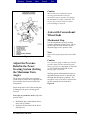
Adjust Maximum Turn Angle
37
Adjust Pressure Relief in Power
Steering
39
Axles with Conventional Wheel Ends 39
Hydraulic Pressure Relief
40
Turning Radius Angle
40
King Pin Inclination
41
Camber Angle
41
Caster Angle
42
Adjust Toe-In
43
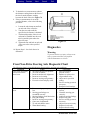
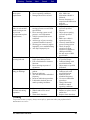
Diagnostics
44
Lubrication
48
King Pins
50
Grease-Lubricated Wheel Bearings 51
Oil Lubricated Wheel Bearings
52
Inspection and Maintenance
52
Checking Draw Key Nuts
53
Checking Steering Knuckle End Play 53
Checking Upper/Lower King Pin
54
Inspect Tie Rod Ends
55
Inspect Tie Rod Assembly
56
Tie Rod End Shop Inspection
58
Tie Rod Service Tips
59
Tie Rods
59
Tightening Draw Key Nuts
60
Checking Steering Arm Bolts
60
Torque Specifications
61
1
Directory
Previous
Previous
Next
Search
Tables
Table A—Front Non-Driving Axle
Table B—Axle Wear Limit
Table C—Bushing Reamer
Dimension
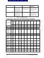
Table D—Camber Angle
Table E—Inspect/Lubrication
Table F—Lubrication/Inspection
2
8
18
23
42
46
46
Exit
Table G—Greasing Intervals
Table H—Wheel End Oil Changes
Table I—Front Axle with
Conventional Wheel
Torque Specifications
Table J—Special Tools
47
48
62
62
All American Front Axle
Directory
Previous
Previous
Next
Search
Exit
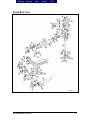
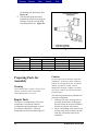
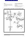
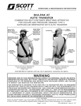
Exploded View
Figure 1
All American Front Axle
3
Directory
Previous
Previous
Next
Search
Exit
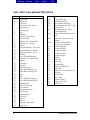
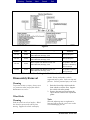
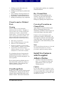
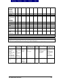
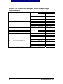
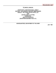
Axle with Conventional Wheel End
Item
A
B
1
2
3
4
5
6
7
8
9
10
11
12
13
14
15
16
17
18
19
20
21
22
23
24
25
26
27
28
29
30
31
32
33
34
35
36
4
Description
Double Nut
Single Nut
Cotter Pin
Castle Nut – Drag Link to
Steering Arm
Steering Arm
Key
Ball Stud
Capscrew and Washer
Grease Fitting
Knuckle Cap – Greaseable
Knuckle Cap – Sealed
Gasket
King Pin Bushing – Easy Steer
King Pin Bushing – Bronze
King Pin Bushing – Nylon
Knuckle
Seal – King Pin Bushing
Castle Nut – Tie Rod Arm to
Knuckle
Cotter Pin
King Pin
Hub Grease Seal
Inner Wheel Bearing Cup
Inner Wheel Bearing Cone
Stud
Hub
Outer Wheel Bearing Cup
Outer Wheel Bearing Cone
Adjusting Nut
Pierced Lock Ring
Lock Washer
Wheel Bearing Nut
“D” Washer
Adjusting Nut
Cotter Pin
Gasket
Hubcap
Capscrew and Washer
Axle Beam
37
38
39
40
41
42
43
44a
44b
45
46
47
48
49
50
51
52
53
54
55
56
57
58
59
60
61
Shims
Tapered Draw Key
Threaded Draw Key
Nut, Threaded Draw Key
Thrust Bearing and “Flat” - Type
Bearing Seal
Thrust Bearing and “Cover” Type Bearing Seal
Integral Thrust Bearing and Oil
Seal
Castle Nut – Steering Arm to
Knuckle
Castle Nut (Flared Base) –
Steering Arm to Knuckle
3/4 Inch Stop Bolt
3/4 Inch Jam Nut
1/2 Inch Stop Bolt
1/2 Inch Jam Nut
3/4 Inch Adapter
Washer
Cotter Pin
Square Key
Woodruff Key
Knuckle Tie Rod Arm
Cotter Pin
Castle Nut – Tie Rod Nut to Tie
Rod End
Tie Rod End
Bolt, Clamp
Locknut, Clamp
Clamp, Cross Tube
Cross Tube
All American Front Axle
Directory
Previous
Previous
Next
Front Axle
Search
Exit
Warning
To prevent serious eye injury, always wear
safe eye protection when you perform
vehicle maintenance or service.
Safety
The purpose of this safety summary is
twofold. First, it is to help ensure the safety
and health of individuals performing service
on, or operation of, the Blue Bird All
American Series bus. Second, it is to help
protect equipment. Before performing any
service or operating procedure on the All
American bus, individuals should read and
adhere to the applicable warnings, cautions
and notes located throughout this Blue Bird
Service Manual.
Warnings
Warnings apply to a procedure or practice
that, if not correctly adhered to, could result
in injury or death. Attention should be paid
to sections of this manual where warnings
appear.
Cautions
Cautions apply to a procedure or practice
that, if not correctly adhered to, could result
in damage to, or destruction of, equipment.
Notes
Notes are used to explain, clarify or
otherwise give additional insight for a given
subject, product or procedure. Note that on
occasion, notes, too, may advise of potential
safety issues.
Introduction
The descriptions and procedures contained
in this maintenance manual are applicable to
all Meritor front non-drive axles.
All American Front Axle
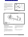
Descriptions
Tie Rod Arm Knuckle and King Pin: The
right tie rod arm is a mirror image of the left
and both are linked by the cross tube
assembly. The right knuckle and king pin
assembly is similar to the left, except that it
does not have a steering arm attached to it in
a manual steering system. A power steering
system uses an auxiliary assist cylinder
attached to the right knuckle that requires a
steering arm in various applications.
Steering Knuckle: Steering knuckles are
rated according to the capacity of the front
axle. All models use straight king pins.
Steering Arms: The steering arm (usually a
forged component) coverts the drag link
force into a turning movement through the
left king pin through the knuckle.
Pitman Arm: The Pitman arm converts the
output torque from the steering gear into the
control force applied to the drag link. This
linkage component connects the steering
gear to the linkage at the center link end.
Tie Rod Assembly: Forged or cast tie rod
assemblies are used on Meritor front nondrive steering axles. The tie rod assembly
links both steering knuckles for uniform
movement and maintains steering control.
Cross Tube and Clamp Assembly: The
cross tube and clamp assembly runs
approximately parallel to the front axle. The
cross tube has right-hand and left-hand
threads on the appropriate side of the
vehicle. Tie rod clamps secure tie rod ends
into the cross tube.
5
Directory
Previous
Previous
Next
Search
Exit
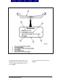
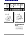
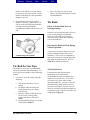
Tie Rod Ends: The tie rod ends include a
ball joint and boot that thread into the cross
tube. Depending on manufacturer design,
tie rod ends can be greaseable or nongreaseable. Tie rod ends are either righthand or left-hand threaded and correspond to
the inside threads at each end of the cross
tube. Figure 2.
Meritor front non-drive steering axles in this
manual feature the components found in
Figure 3.
Figure 2
Figure 3
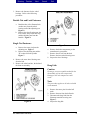
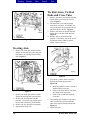
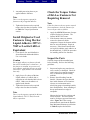
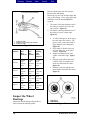
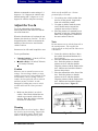
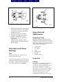
Identification
The entire necessary axle build information,
including assembly date, for any Meritor
front non-drive axle is indicated on the axle
identification tag.
The identification tag is fastened to the
center of the beam at the front surface. The
axle assembly date is either located in the
lower right hand or left hand corner of the
tag.
6
The Julian dating method is currently used
to indicate the axle assembly date. The first
two digits indicate the year, and the last
three digits indicate the day of the year.
Figure 4.
For example, "95327" would reflect the
327th day of 1995 (November 22nd)
.
All American Front Axle
Directory
Previous
Previous
Next
Search
Exit
Figure 4
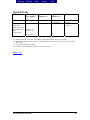
To identify the model number, refer to the
identification plate on the front of the beam.
Use the complete model number to order
parts. Figure 5.
All American Front Axle
For a description of all models, refer to
Table A.
7
Directory
Previous
Previous
Next
Search
Exit
Figure 5
Model
Number
Capacity
(lbs)
FF-966
12,000
FF-967
13,200
Wheel End and Knuckle Type
Bottle Spindle with Bolted Tie Rod Arm
Individual Hub, Bearings, Seals
Bottle Spindle with Bolted Tie Rod Arm
Individual Hub, Bearings, Seals
FF-944
13,200
Bottle Spindle with Bolted Tie Rod Arm
Individual Hub, Bearings, Seals
FG-943
14,600
Bottle Spindle with Bolted Tie Rod Arm
Individual Hub, Bearings, Seals
Major Design
Variation
Straight King Pin
Straight King Pin
5" Drop from Center
of Spindle to Pad and
Special Tie Rods/Easy
Steer™ Design
5" Drop from Center
of Spindle to Pad/Easy
Steer™ Design
Table A: Front Non-Driving Axle Model Number Information
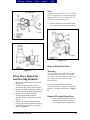
Disassembly/Removal
stands. Do not work under a vehicle
supported only by jacks. Jacks can slip and
fall over. Serious personal injury can result.
Warning
To prevent serious eye injury, always wear
eye protection when you perform vehicle
maintenance or service.
Wheel Ends
Warning
Park the vehicle on a level surface. Block
the wheels to prevent the vehicle from
moving. Support the vehicle with safety
8
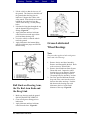
1. Raise the front of the vehicle until the
front wheels are off the floor. Support
the vehicle with safety stands.
2. Remove the capscrews that fasten the
cap to the hub. Remove the cap and the
gasket.
Note
When the adjusting nuts are tightened or
loosened, always use the correct size socket
to avoid damaging the nut.
All American Front Axle
Directory
Previous
Previous
Next
Search
Exit
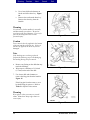
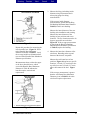
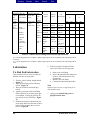
3. Remove the fasteners for the wheel
bearings. Refer to the following
procedure.
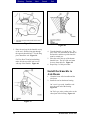
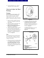
Double Nut and Lock Fasteners
a. Bend the tabs of the flattened lock
washer away from the wheel
bearing nut and the adjusting nut.
Figure 6.
b. Remove the wheel bearing nut, the
lock washer, the pierced lock ring,
and the adjusting nut from the
knuckle. Figure 6.
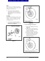
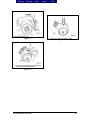
Single Nut Fasteners
Figure 7
a. Remove the cotter pin from the
adjusting nut. Figure 7.
b. Remove the adjusting nut and the
"D" washer from the spindle.
Figure 7.
4. Remove the outer wheel bearing cone
from the hub.
5. Remove the wheel and tire, the hub and
the drum as assembly.
6. Remove the brake components per the
manufacturer's procedures.
7. Remove the oil seal from the hub.
Remove the inner wheel bearing cone.
8. Inspect the wheel bearings.
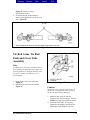
Drag Link
Caution
Heating is not an acceptable method for the
disassembly of front axle components.
Damage to the axle components could
result.
Note
This procedure applies to all axles included
in this manual.
Figure 6
All American Front Axle
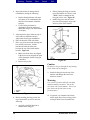
1. Remove the cotter pins from the ball
studs.
2. Remove the nuts from the ball studs.
3. Disconnect the drag link from the
Pitman arm and the steering arm.
Figure 7.
4. Inspect the drag link.
9
Directory
Previous
Previous
Next
Search
Exit
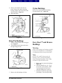
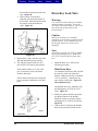
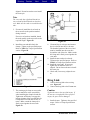
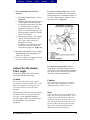
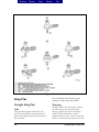
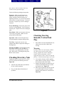
Tie Rod Arms, Tie Rod
Ends and Cross Tube
Figure 7
1. Remove the cotter pins and the nuts that
fasten each tie rod end to the tie rod
arms. Figure 9.
2. Disconnect the cross tube assembly
from the tie rod arms. If available, use
tie rod end puller to separate the tie rod
end from the tie rod arm. Figure 9.
3. Remove the cotter pin and the nut that
fasten the tie rod arms in the knuckle.
Figure 9.
4. Remove the tie rod ends from the
knuckle. If necessary, tap on the end of
the knuckle with a leather or plastic
mallet. Remove the key.
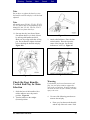
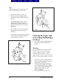
Steering Arm
1. Remove the cotter pin and the nut that
fastens the steering arm to the drag link.
Disconnect the steering arm from drag
link. Figure 8.
Figure 9
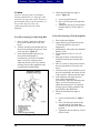
5. If necessary, remove the tie rod ends.
Refer to the following procedure.
Figure 10.
Figure 8
2. Remove the cotter pin and the nut that
fastens the steering arm to the knuckle.
3. Remove the steering arm from the
knuckle. If necessary, tap on the end of
the rod with a leather or plastic mallet.
4. Remove the key from the steering arm.
5. Inspect the steering arm.
10
a. Mark the position each tie rod end is
installed in the cross tube.
b. Remove the bolts and the nuts from
the clamp on the cross tube.
c. Remove the tie rod ends from the
cross tube.
6. The rotating style clamp on cross tubes
can be rotated for easier accessibility
when removing the clamp bolt and nut.
Figure 11.
7. Inspect the parts.
All American Front Axle
Directory
Previous
Previous
Next
Search
Exit
Note
All models except FC-901, FC-921, FE-970,
FF-971 and FL-901 use threaded draw keys.
Models FC-901, FC-921, FE-970, FF-971
and FL-901 use plain draw keys.
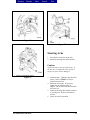
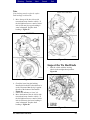
6. Remove the plain or the threaded draw
keys. Refer to the following procedure.
Figure 10
Figure 12
Remove Plain Draw Keys
Figure 11
Draw Keys, King Pins
and Steering Knuckle
1. Remove the wheel ends as described in
this section.
2. Vent the air from the brake system.
Disconnect the air lines from the brakes.
3. Remove the brake components. Refer to
procedures from the brake manufacturer.
4. Remove the tie rod arms and the
steering arm (left side) from the
knuckle. Refer to the procedure in this
section.
5. Remove the capscrews that fasten the
kin pin caps to the top and the bottom of
the knuckle. Remove the caps and the
gaskets. Figure 12.
All American Front Axle
Warning
Use a brass or leather mallet for assembly
and disassembly procedures. Do not hit
steel parts with a steel hammer. Pieces of a
part can break off and cause serious
personal injury.
Use a brass hammer and a steel drift to
remove the draw key. Place the drift on the
small ("D"-shaped) end of the key. Figure
13.
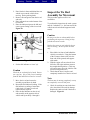
Remove Threaded Draw Keys
a. Loosen the threaded draw key lock
nut until the top of the lock nut is
even with the end of the draw key.
11
Directory
Previous
Previous
Next
Search
Exit
b. Use a brass drift and a hammer to
hit the end of the draw key. Figure
14.
c. Remove the nut from the draw key.
Remove the draw key from the
knuckle.
Warning
Use a brass or leather mallet for assembly
and disassembly procedures. Do not hit
steel parts with a steel hammer. Pieces of a
part can break off and cause serious
personal injury.
Figure 13
Caution
Force must be directly applied to the bottom
of the nut and the end of the key. If force is
not directly applied, the draw key will be
damaged.
Note
If the bushings are not being replaced,
perform the following to prevent damaging
the bushing during kin pin removal.
•
•
Remove any flaring on the drift that may
touch the bushings.
Wrap tape to a thickness of 1/16 inch
(1.5 mm) on the end of the drift.
Figure 14
7. Use a brass drift and a hammer to
remove the king pins from the knuckle.
Figure 15.
If the king pin is hard to remove, use a
hydraulic king pin remover. Refer to
Table J in Special Tools section.
Warning
Wear gloves when you remove or install
shims. Shims have sharp edges that can
cause injury.
Figure 15
12
All American Front Axle
Directory
Previous
Previous
Next
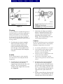
8. Remove the knuckle from the axle
beam. Remove the shims, the thrust
bearing, and the seal between the beam
and the knuckle. Figure 16.
9. Inspect the parts.
Search
Exit
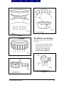
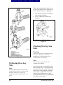
Nylon Bushings
Remove the top and the bottom bushing
from the knuckle bore. Figure 18.
Figure 16
King Pin Bushings
1. Remove and discard the lower king pin
seal. Figure 17.
2. Turn knuckle upside down and remove
the upper king pin seal.
Figure 18
Easy Steer™ and Bronze
Bushings
Warning
Observe all warnings and cautions provided
by the press manufacturer to avoid damage
to components and serious personal injury.
Note
On FF-, FG-, and FL-Series axles, the
bushings can be removed with Bushing
Service Kit from Kent-Moore Tools. Refer
to Table J in Special Tools section.
Figure 17
3. Remove the old bushings as follows.
All American Front Axle
a. Make a tool to remove the bushings.
Figure 19.
b. Place the knuckle in a vise. Use a
press with a 5-ton capacity. Make
sure the knuckle does not move
when the bushings are removed.
c. Install the tool into the upper king
pin bushing. Press the upper king
13
Directory
Previous
Previous
Next
Search
Exit
pin bushing from the knuckle bore.
Figure 20.
d. Turn knuckle upside down and
install the tool in the lower king pin
bushing. Press the lower bushing
from the knuckle bore. Figure 20.
Figure 20
Axle Model
Number
FF-966
FF-967
FF-944
FF-943
Dimension X
Dimension Y
(+ 0.001 in)
(+0.025 mm)
(+ 0.001 in)
(+ 0.025 mm)
1.786
1.786
1.786
1.786
45.364
45.364
45.364
45.364
1.911
1.911
1.911
1.911
48.539
48.539
48.539
48.539
Figure 19 - Dimensions for Bushing Removal and Installation Tool
Preparing Parts for
Assembly
Warning
To prevent serious eye injury, always wear
safe eye protection when you perform
vehicle maintenance or service.
Repair Parts
The repair or reconditioning of front axle
components is not allowed. Meritor
recommends replacing damaged or out-ofspecification components. All major
components are heat treated and tempered.
14
Caution
Do not bend, weld, or heat any front axle
component. If the axle is bent, welded or
heated, the strength of the axle is reduced
and the warranty is voided. An axle
damaged by bending, welding, or heating
may cause a vehicle accident and serious
personal injury.
The following operations are prohibited on
front axle components.
1. Welding of or to the steering arms, tie
rod arms, the knuckles, the king pins,
the axle beams, the tied rod assemblies,
the hubs, the drums, or the brakes.
2. Hot or cold bending of the knuckles, the
steering arms, the tie rod arms, the ball
studs, the axle beams or the tie rod
assemblies.
All American Front Axle
Directory
Previous
Previous
Next
3. Drilling out of the holes in the axle
beam for the king pins.
4. Drilling out of the draw key holds in the
knuckle.
5. Spray welding of bearing diameters on
the knuckles or in the machined bores.
6. Disassembly of unitized truck hub unit.
7. Milling or machining of any component.
Clean Ground or Polished
Parts
Warning
Solvent cleaners can be flammable,
poisonous and cause burns. Examples of
solvent cleaners are carbon tetrachloride,
emulsion-type cleaners, and petroleumbased cleaners. To avoid serious personal
injury when you use solvent cleaners, you
must carefully follow the manufacturer's
product instructions and these procedures.
•
•
•
•
•
Wear safe eye protection
Wear clothing that protects your skin.
Work in a well-ventilated area.
Do not use gasoline, or solvents that
contain gasoline. Gasoline can explode.
You must use hot solution tanks or
alkaline solutions correctly. Follow the
manufacturer's instructions carefully.
Use a cleaning solvent to clean ground or
polished parts and surfaces. Kerosene or
diesel fuel can be used for this purpose. Do
not use gasoline.
Do not clean ground or polished parts in a
hot solution tank or with water, steam, or
alkaline solutions. These solutions will
cause corrosion of the parts.
Search
Exit
hot solution tanks until they are completely
cleaned and heated.
Dry Cleaned Parts
Parts must be dried immediately after
cleaning. Dry parts with clean paper or
rages, or compressed air. Do not dry
bearings by spinning with compressed air.
Corrosion Prevention on
Cleaned Parts
Apply light oil to cleaned and dried parts
that are not damaged and are to be
immediately assembled. Do NOT apply oil
to the brake linings or the brake drums.
If parts are to be stored, apply a good
corrosion preventative to all surfaces. Do
NOT apply the material to the brake linings
or the brake drums. Store the parts inside
special paper or other material that prevents
corrosion.
Note
Be sure that all tapered joints are clean and
dry with no lubrication or corrosion
preventative applied to mating surfaces.
Install New Fasteners
with Pre-applied
Adhesive Patches
1. Clean the oil and dirt from threaded
holes. Use wire brush to remove old
patch material. There is no special
cleaning required.
Caution
Clean Rough Parts
Rough parts can be cleaned with the ground
or polished parts. Rough parts also can be
cleaned in hot solution tanks with a weak
alkaline solution. Parts must remain in the
All American Front Axle
Do not apply adhesives or sealants on new
fasteners with pre-applied adhesive patches
or in the threaded holes. If other adhesives
or sealants are used, the new adhesive will
not function correctly.
15
Directory
Previous
Previous
Next
2. Assemble parts using the new preapplied adhesive fasteners.
Note
There is no drying time required for
fasteners with pre-applied adhesive.
3. Tighten the fasteners to the required
torque value for that size fastener. Refer
to Table I in Torque Specification
section.
Install Original or Used
Fasteners Using Meritor
Liquid Adhesive 2297-C7049 or Loctite® 680 or
Equivalent
1. Clean the oil, dirt, and old adhesive
from all threads and threaded holes.
Use a wire brush.
Caution
Do not apply adhesive to fastener threads
that will be installed into a closed bore. As
the fastener is installed, air pressure will
force adhesive applied to fastener out of the
closed bore. Apply adhesive into threaded
bore only.
2. Apply four or five drops of Meritor
Liquid Adhesive, Loctite® 680, or
equivalent to each threaded hole or bore
ONLY. Make sure the adhesive is
applied to the threads.
3. Tighten the fasteners to the required
torque value for that size fastener.
Note
There is no drying time required for Meritor
Liquid Adhesive 2297-C-7049, Loctite®
680, or equivalent.
16
Search
Exit
Check the Torque Values
of Dri-Loc Fasteners Not
Requiring Removal
Note
If Dri-Loc fasteners do not require removal
from components, check the fasteners for
correct torque value as follows.
1. Apply the MINIMUM amount of torque
required for that size fastener. The
fastener MUST NOT rotate.
2. If the fastener rotates any amount,
remove the fastener from the
component. Inspect the fastener and the
hole for wear and damage. Repair as
necessary. If the fastener and the hole
are in good condition, apply adhesive to
the threaded hole. Follow the procedure
for installing old Dri-Loc fasteners.
Inspect the Parts
Carefully inspect all disassembled parts
before assembly. Refer to the following
guidelines.
1. Inspect and replace any parts that are
worn, cracked, or damaged. Check for
cracks using dye penetrant, magnetic
flux, or fluorescent particle testing
methods.
2. Remove the old bushing from the
knuckle. Measure the upper knuckle
bore inside diameter at two locations.
Always use a micrometer and a
telescoping gauge when taking knuckle
bore measurements. Some rounding of
the top and bottom bore edges is
acceptable.
Measure the bore in four positions and
at two locations. The two locations
must be 90 degrees opposed from each
other. Figure 20. If the average
measurement is more than the Knuckle
Bore Maximum Diameter specification
in Table B, replace the knuckle.
All American Front Axle
Directory
Previous
Previous
Next
Search
Exit
3. Measure the king pin bushing inside
diameter using a micrometer and a
telescoping gauge for taking
measurements.
If the average inside diameter
measurement is greater than the King
Pin Bushing Maximum Inner Diameter
Table B, install a new bushing.
Figure 20
Repeat this procedure for measuring the
lower knuckle bore. Figure 21. Refer
to the Knuckle Bore Maximum
Diameter indicated in Table B. Verify
the average inside bore dimension does
not exceed the Knuckle Bore Maximum
Diameter specifications.
Measurements taken at either the upper
or the lower knuckle bores, which
exceed the Knuckle Bore Maximum
Diameter in Table B, indicate the
knuckle requires removal and
replacement.
Measure the inner diameter of the new
bushing after installation and reaming.
Measure the inner diameter of the
bushing in four positions and at two
locations. The two locations must be 90
degrees opposed from each other.
Figure 20. If the average measurement
is more than the King Pin Bushing
Maximum Inner Diameter specification
in Table B, replace the bushing.
4. Measure the inner bore diameter of the
axle beam. Rounding at the top and
bottom of the beam is acceptable.
Measure the axle beam bore at four
positions, Figure 20, and at two specific
locations: 1/2 inch (12.7 mm) below the
top of the bore and 1/2 inch (12.7 mm)
above the bottom of the bore. Figure
22.
If the average measurement is greater
than the Axle Beam Bore Maximum
Diameter given in Table B, the entire
axle beam requires replacement.
Figure 21
All American Front Axle
17
Directory
Previous
Previous
Next
Search
Exit
Remove all lubricant from the bearings,
knuckle, hub, and hubcap.
Inspect the cup, the cone and the rollers and
cage of all bearings. If any of the following
conditions exist, the bearing MUST be
replaced.
1. The center of the large diameter end of
the rollers is worn level or below the
outer surface. Figure 23.
2. The radius at the large diameter end of
the rollers is worn to a sharp edge.
Figure 23.
•
Figure 22
•
Model
Number
FF-966
FF-967
FF-944
FF-943
Knuckle
Bore
Max.
Diameter
Beam
Bore
Max.
Diameter
King Pin
Bushing
Max
Inner
Diameter
1.9220
inch
(48.818
mm)
1.7980
inch
(45.6692
mm)
1.7960
inch
(45.6180
mm)
1.9220
inch
(48.818
mm)
1.9220
inch
(48.818
mm)
1.9220
inch
(48.818
mm)
1.7980
inch
(45.6692
mm)
1.7980
inch
(45.67692
mm)
1.7980
inch
(45.6692
mm)
1.7960
inch
(45.6180
mm)
1.7960
inch
(45.6180
mm)
1.7960
inch
(45.6180
mm)
•
•
•
A visible roller groove in the cup or
the cone inner race surfaces. The
groove can be seen at the small or
large diameter end of both parts.
Figure 24.
Deep cracks or breaks in the cup,
the cone inner race, or the roller
surfaces. Figure 24.
Bright wear marks on the outer
surface of the roller cage. Figure
25.
Damage on the rollers and on the
surfaces of the cup and the cone
inner race that touch the rollers.
Figure 26.
Damage on the cup and the cone
inner surfaces that touch the rollers.
Figure 27.
Table B – Axle Wear Limit Specifications
Inspect the Wheel
Bearings
Inspect the wheel bearings when the hub is
removed from the knuckle spindle.
Figure 23
18
All American Front Axle
Directory
Previous
Previous
Next
Search
Exit
Figure 27
Figure 24
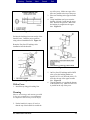
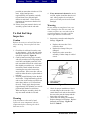
Tie Rod Grease Fittings
When inspecting the tie rod, observe the
following.
1. If a grease fitting is missing, install a
new one. Do not attempt to install a
fitting if the tie rod end is a nongreaseable design. Figure 28.
2. Tighten all grease fittings to the
specified torque. Figure 29.
Figure 25
Figure 28
Figure 26
All American Front Axle
19
Directory
Previous
Previous
Next
Search
Exit
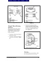
2. Be sure that the bushing lube slots align
with the grease ports in the knuckle.
Figure 30.
Figure 29
Assembly
Warning
To prevent serious eye injury, always wear
safe eye protection when you perform
vehicle maintenance or service.
Installation
King Pin Bushings
Nylon Bushings
Insert the nylon bushing in each knuckle
bore by hand. Be sure that the entire outer
surface of the nylon bushing is in contact
with the knuckle bore.
Check the nylon bushing installation before
attempting to install the knuckle to the axle
beam noting the following.
1. Verify that each nylon bushing is fully
seated in the knuckle bore by passing
the king pin through the upper and lower
bores after insertion.
Note
Figure 30
Bronze and Easy Steer™
King Pin Bushings—Axles
with Conventional Wheel
Ends
Without a Press
Note
On the FF-, FG- and FL- Series axles, the
bushings can be installed without a press.
Use the Bushing Service Kit from Kent
Moore Tools to install and ream the
bushings.
Bronze and Easy Steer™ bushings have an
interference fit in the knuckle bores and
require a suitable installation tool for
bushing installation. Figure 31.
The nylon bushing installation is not a press
fit in the knuckle bore as in cases where a
bronze or Easy Steer™ bushing issued.
20
All American Front Axle
Directory
Previous
Previous
Next
Search
Exit
top of the press. Make sure tops of the
bores are parallel to the top of the press.
3. Place new bushing in the upper knuckle
bore.
4. Using installation tool, press start the
bushing 1/8 inch (3 mm) into the upper
bore. Release the pressure. Make sure
the bushing is straight into the upper
bore. Figure 33.
Figure 31
Position the bushings into outer end(s) of the
knuckle bores. Install to proper position
using selected installation tool. Figure 32.
Ream the Easy Steer™ bushings after
installation into the knuckle.
Figure 33
Figure 32
With a Press
1. Install the top king pin bushing first.
5. On Easy Steer™ bushings and for MFS
axles, press the bushing farther to a
depth of 0.352- to 0.382-inch (8.94-9.70
m) below the top of the upper knuckle
bore. Figure 34.
6. Turn the knuckle over so that the bottom
of the knuckle is up. Make sure the bore
is parallel to the top of the press.
Warning
Observe all warnings and cautions provided
by the press manufacturer to avoid damage
to components and serious personal injury.
2. Put the knuckle in a press, if used, so
that the top of the knuckle is toward the
All American Front Axle
21
Directory
Previous
Previous
Next
Search
Exit
Note
Reamer tools are available from SPX-Kent
Moore at 1-800-328-6657 and from Wright
Tool Company at 1-800-783-9826.
1. Place the knuckle in a vise with brass
jaws.
2. Refer to Figure 35 for the dimensions of
the reamer tool.
Figure 34
7. Place new bushing in lower knuckle
bore.
8. Using installation tool, press start the
bushing 1/8 inch (3 mm) into the lower
bore. Release the pressure. Make sure
the bushing is straight into the lower
bore. Figure 33.
9. On Easy Steer™ bushings, press the
bushing farther to a depth of 0.352- to
0.382-inch (8.94-9.70 mm) below the
top of the lower knuckle bore (as viewed
with the knuckle upside down). Figure
34.
10. Ream the bushings. Refer to the
procedures in this section.
Reaming the King Pin
Bushings
Bronze and Easy Steer™
Bushings
Caution
Figure 35
3. Slide the pilot of the reamer through the
top bushing until the reamer blades
touch the bushing. Figure 36.
4. Rotate the reamer with a light
downward pressure. Do not apply too
much force. Rotate the reamer
smoothly.
5. After the reamer cuts most of the top
bushing, make sure the tool does not
drop to the bottom bushing.
6. After cutting the top bushing, guide the
reamer into the bottom bushing. Repeat
Steps 3-5. Figure 37.
7. Slide the reamer out of the bottom
bushing. If the reamer must be removed
through the top bushing, rotate the tool
in the opposite cutting direction.
8. Clean all material from the bushings.
Do not hone or burnish the bushings. The
bushings will be damaged by honing or
burnishing.
22
All American Front Axle
Directory
Previous
Previous
Next
Search
Exit
Bushing Reamer Dimensions
Axle
Model
Lower Pilot
Diameter
Dimension
"A" (- 0.001
inch or +
0.0245 mm)
Inch Mm
Blade
Diameter
Dimension "B"
(+0.001-inch
or +0.0245
mm)
Inch
Mm
Upper Pilot
Diameter "C"
(+0.001 inch or
+0.0245 mm)
Inch
Mm
Inch
Mm
Inch
Mm
FF-966
FF-967
FF-944
FG-943
1.7800
1.7800
1.7800
1.7800
1.7955
1.7955
1.7955
1.7955
1.7900
1.7900
1.7900
1.7900
45.4660
45.4660
45.4660
45.4660
10.25
10.25
10.25
10.25
260.35
260.35
260.35
260.35
12.25
12.25
12.25
12.25
311.15
311.15
311.15
311.15
45.2120
45.2120
45.2120
45.2120
45.6057
45.6057
45.6057
45.6057
Lower Pilot
Length
Dimension "D"
Upper Pilot
Length
Minimum
Dimension "E"
Table C: Bushing Reamer Dimensions
Figure 36
Figure 37
Inner Knuckle Bore King
Pin Seals
1. Place the top of the knuckle in a vise
with brass jaws. The bottom of the
knuckle must be toward you.
2. Place the seal in the bottom of the top
knuckle bore. The lip of the seal must
be away from the bore. Figure 38.
All American Front Axle
23
Directory
Previous
Previous
Next
Search
Exit
Figure 38
Figure 40
3. Place the end cap for the knuckle on top
of the seal. Slide the king pin through
the opposite knuckle bore. Use the king
pin to install the seal. Figure 39.
For Easy Steer™ and nylon bushing,
make sure the top of the seal is even
with top of the knuckle. Figure 40.
4. Turn the knuckle over in the vise. The
jaws of the vise must hold the bottom of
the knuckle, and the top of the knuckle
must be toward you.
5. Place the seal in the top of the bottom
knuckle bore. The lip of the seal must
be away from the bore. Figure 38.
6. Repeat step 3 of this procedure.
Install the Knuckle to
Axle Beam
1. Clean the bores of the knuckle and the
axle beam.
2. Install the seal on the thrust bearing.
On "cover" type seals, install the seal
over the open end of the bearing.
Figure 41.
On "flat" type seals, put the seal over the
closed part of the bearing. Figure 41.
Figure 39
24
All American Front Axle
Directory
Previous
Previous
Next
Search
Exit
Figure 41
Integral Thrust Bearing
and Seal
The one-piece thrust bearing with an
integrated grease seal is completely
interchangeable with the two-piece
design. It has a specified top and
bottom orientation.
•
•
Figure 42
3. Place the seal and thrust bearing
assembly on the inner knuckle. Make
sure the seal will face upward toward
the beam. The top inner diameter will
be in contact with the bottom of axle
beam. Figure 43.
The surface with the inner diameter
seal must be on top.
The surface with the outer diameter
seal must be on the bottom. Figure
42.
Figure 43
Warning
Wear gloves when you install shims. Shims
have sharp edges that can cause injury.
All American Front Axle
25
Directory
Previous
Previous
Next
4. Inspect the shims for damage before
reinstallation, noting the following.
•
•
Replace damaged shims with same
size shims (or in combination) that
allow the least amount of knuckle
end play.
If a new shim pack must be
determined, select the amount of
shims that will give the least amount
of end play.
Search
Exit
•
•
Before placing the king pin into the
top of the knuckle, be sure the word
"TOP" (which is stamped on the
king pin) can be seen. Figure 45.
Rotate king pin so that two draw
key slots of pin properly align with
draw key slots in the knuckle.
5. After inspection, place shims on top of
axle beam bore machined surface.
Align shims for king pin installation.
6. Place the knuckle on the axle beam.
7. Place a pry bar between the steering arm
boss and the axle beam. Lift the
knuckle and slide the shim pack
between the top of the beam and the
knuckle. Figure 44.
•
•
Make sure all the bores are aligned.
If the bores are not aligned, the parts
will be damaged when the king pin
is installed.
Remove the pry bar.
Figure 45
Caution
Do not force the pin through the top bushing
or the shims will be damaged.
9. Install the king pin into the top of the
knuckle and through the area where
shims are located.
Warning
Use a brass or leather mallet for assembly
and disassembly procedures. Do not hit
steel parts with a steel hammer. Pieces of a
part can break off and cause serious
personal injury.
Figure 44
8. Before installing the king pin into the
top of the knuckle, be sure to note the
following.
•
26
10. If required, use a hammer and a brass
drift to apply direct force to king pin for
seating it into the lower knuckle bore.
Apply the specified lubricant to
bottom half of king pin.
All American Front Axle
Directory
Previous
Previous
Next
Search
Exit
Note
Do not drive or tighten the draw keys into
the knuckle until the end play is checked and
adjusted.
Note
All models except FC-901, FC-921, FE-970,
FF-971 and FL-901 use threaded draw keys.
Models FC-901, FC-921, FE-970, FF-971
and FL-901 use plain draw keys.
11. Seat top draw key into front of beam.
Seat bottom draw key in back of beam
by striking with hammer and drift.
Make sure keys align with slots of king
pin. Do not install or tighten lock nuts
before checking the knuckle end play.
Figure 45A.
Figure 46
3. Attach a dial indicator. Place the base
on the knuckle. Place the tip on the
center of the king pin. Set the dial
indicator on "zero" (0). Figure 47.
Figure 47
Figure 45A
Check the Steer Knuckle
Vertical End Play for Shim
Selection
1. Strike the boss of the knuckle with a
rubber mallet to move the parts in
position. Figure 46.
2. Turn the knuckle to the straight
(forward) position.
Warning
If a hydraulic jack is used to measure end
play, use two safety stands to support the
axle in the rest position. If safety stands are
not used, the axle can fall. Serious personal
injury can occur.
4. Use one of the following procedures to
measure the end play.
•
All American Front Axle
Place a pry bar between the knuckle
and the top of the axle center. Push
27
Directory
•
Previous
Previous
Next
the knuckle up and measure the end
play. Figure 48.
Place a block of wood and a
hydraulic jack under the bottom of
the knuckle. Raise the knuckle until
the pointer on the dial indicator
stops. Figure 49.
Search
Exit
Draw Key Lock Nuts
Warning
Use a brass or leather mallet for assembly
and disassembly procedures. Do not hit
steel parts with a steel hammer. Pieces of a
part can break off and cause serious
personal injury.
Caution
Make sure the draw key is installed
completely or the lock nut is tightened to the
specified torque. If not installed correctly,
the king pin and the axle beam will be
damaged.
Note
Figure 48
5. Repeat Steps 3 and 4 with the axle in the
full right and full left turn positions.
6. The end play must be 0.001 to 0.025
inch (0.025-0.635 mm) in all positions.
If the knuckle binds or "0" (zero) end
play is measured, remove the shims
from the shim pack.
If more than 0.025-inch (0.635 mm) end
play is measured, add shims to the shim
pack.
All models except FE-970, FF-971 and FL901 use threaded draw keys. Models FE970, FF-971 and FL-901 use plain draw
keys.
1. Install the draw keys. Refer to the
following procedure.
Plain Draw Keys
Use a hammer and a brass drift to install
the draw key in the axle beam and
knuckle. Make sure the key is installed
1/32 to 1/8 inch (1-3 mm) below the
outer surface of the beam. Figure 50.
Threaded Draw Keys
On threaded draw keys, install the lock
nut and tighten to 30-45 lb-ft (41-61
N•m). Figure 51.
2. Install new gaskets and the caps on the
top and the bottom of the knuckle.
Install the capscrews and the washers
and tighten to 20-30 lb-ft (28-40 N•m).
Figure 52.
3. Connect the tie rod arm to the knuckle.
Refer to the procedure in this section.
Figure 49
28
All American Front Axle
Directory
Previous
Previous
Next
Search
Exit
Figure 50
Figure 52
Steering Arm
1. Press the key in the slot in the arm.
2. Install the steering arm in the knuckle.
Caution
Tighten the nuts to the specified torque. If
the nuts are not tightened to the specified
torque, the parts will be damaged.
Figure 51
3. Install the nuts. Tighten to the specified
torque. Refer to Table I in Torque
Specification section.
4. Install the cotter pins. If necessary,
tighten the nut until the holes are
aligned. Do not loosen the nut to install
the cotter pin.
5. Lubricate the drag link end that connects
to steering arm. Refer to Lubrication
section
6. Check for correct operation.
All American Front Axle
29
Directory
Previous
Previous
Next
Search
Exit
Figure 54
Figure 53
Note
Tie Rod Ends into the
Cross Tube
Refer to Figure 54
The cross tube has right-hand threads on the
right side of the vehicle and left-hand
threads on the left side of the vehicle. Make
sure the tie rod end threads are correctly
installed into the tube deeper than the end of
the cross tube slot. Figure 55.
replacement tube should have the same
length and diameter as the original
removed tube that couples with the tie
rod ends. Use the thread count as a
guide and install the tie rod ends into the
threaded cross tube ends to the
approximate depth marked during the tie
rod assembly removal.
Both tie rod ends must be installed into
the cross tube deeper than the end of the
cross tube slot. Figure 56.
2. If you are installing new tie rod ends:
Thread the tie rod ends to the
approximate original depth inside the
cross tube. Figure 56.
Figure 55
1. If you are only replacing the cross
tube: When replacing the cross tube, be
certain that the replacement cross tubes
is properly specified from OE
manufacturing standards. The
30
Both tie rod ends must be installed into
the cross tube deeper than the end of the
cross tube slot. Figure 56.
3. Install the nuts and the bolts in the
clamps. Tighten to the specified torque.
All American Front Axle
Directory
Previous
Previous
Next
Search
Exit
Figure 55. Refer to Torque
Specification section.
4. Check that the tab on the clamps is
firmly seated against the end of the cross
tube. Figure 59.
Figure 56
Tie Rod Arms, Tie Rod
Ends and Cross Tube
Assembly
Note
If a different tie rod arm is installed (such as
for increasing the maximum turn angle), the
steering geometry is changed and may cause
tire wear. Contact your Meritor service
representative.
1. Press the key in the slot in the arm.
Figure 57.
2. Install the tie rod arm in the knuckle.
Figure 57.
Figure 57
Caution
Tighten the nuts to the specified torque. If
the nuts are not tightened to the specified
torque, the parts will be damaged.
3. Install the nut on the tie rod arm.
Tighten to the specified torque. Refer to
Table I in Torque Specification section.
4. Install the cotter pins. If necessary,
tighten the nut slightly, increasing the
final torque value until the holes are
All American Front Axle
31
Directory
Previous
Previous
Next
Search
Exit
aligned. Do not loosen the nut to install
the cotter pin.
Note
The cross tube has right-hand threads on
one end and left-hand threads on the other
end. Make sure the ends are installed on the
tube.
5. If removed, install the tie rod ends on
the cross tube to the position marked
during removal.
If new tie rod ends are installed, thread
the ends equally on the cross tube to the
required length. Figure 58.
6. Install the nuts and the bolts in the
clamps. Tighten to the specified torque.
Refer to Table I in Torque Specification
section. Figure 58.
Figure 59
8. Clean and dry tie rod taper and connect
the tie rod ends into the tie rod arms.
The threaded portion of the tie rod end
must be installed into the cross tube
beyond the end of the slot. Make certain
the clamp tab is firmly seated against the
cross tube.
9. Install the nuts on the tie rod ends.
Tighten to the specified torque. Refer to
Table I in Torque Specification section.
10. Install the cotter pins. If necessary,
tighten the nut until the holes are
aligned. Do not loosen the nut to install
the cotter pin.
11. Check and, if necessary, adjust the toein.
Drag Link
Figure 58
7. The rotating style clamp on cross tubes
can be rotated for easier accessibility
when installing the clamp bolt and nut.
Tighten nut sufficiently to engage the
locking element of the nut with the bolt.
Clamp and tie rod end must be free to
rotate. Make certain the clamp tab is
firmly seated against the cross tube.
Figure 59.
32
1. Connect the drag link to the steering
arm. Figure 60.
2. Connect the drag link to the Pitman arm.
Caution
Tighten the nuts to the specified torque. If
the nuts are not tightened to the specified
torque, the parts will be damaged.
3. Install the nuts. Tighten to the specified
torque. Refer to Torque Specification
section.
All American Front Axle
Directory
Previous
Previous
Next
4. Install the cotter pins. If necessary,
tighten the nut until the holes are
aligned. Do not loosen the nut to install
the cotter pin.
5. Lubricate the drag link. Refer to
Lubrication section.
6. Check for correct operation.
Search
Exit
Adjustments
Warning
To prevent serious eye injury, always wear
safe eye protection when you perform
vehicle maintenance or service.
Inspection Before Alignment
Check the following before doing a front
wheel alignment.
Inspection
Refer to section on Lubrication, Inspection
and Maintenance.
Wheels and Tires
Check the following items.
Figure 60
Install the Brake
Components and Wheel
Ends
1. Install the brake assembly on the
knuckle.
2. Lubricate the wheel bearings. Refer to
Lubrication section
3. Install the outer wheel bearing cone in
the hub. Install the adjusting nut.
4. Adjust the wheel bearings. Refer to
section entitled "Check and Adjust the
Wheel Bearings". Refer to the wheel
end hardware manufacturer's procedures
if necessary.
5. Install the cap and the gasket on the hub.
Install the capscrews and tighten to 2030 lb-ft (27-41 N•m).
6. Install the wheel and tire assembly.
7. Lower the vehicle to the ground. Check
for correct operation.
8. Check and adjust the toe-in.
•
•
•
•
•
Make sure the tires are inflated to the
specified pressure.
Make sure the front tires are the same
size and type.
Make sure the lug nuts are tightened to
the specified torque.
Make sure the wheels are balanced.
Check for bent or damaged wheels.
Front Suspension
Check for the following items.
•
•
•
Make sure all fasteners are tightened to
the specified torque.
Inspect the leaf springs for wear and
damage.
Inspect the shock absorbers for wear and
damage.
Rear Axle and Rear
Suspension
Front tire wear can be caused by the rear
axle. If the outer edge of one front tire is
All American Front Axle
33
Directory
Previous
Previous
Next
Search
Exit
worn and the inner edge of the other front
tire is worn, check the following.
Major Front Wheel
Adjustment
•
Perform a major front wheel alignment to
correct steering and tire wear conditions.
•
•
•
•
•
•
Make sure all fasteners are tightened to
the specified torque.
Make sure the leaf springs are not worn
or damaged.
Make sure the bushings in the leaf
springs are not worn or damaged.
Make sure the torque rods (if used) are
correctly adjusted.
Make sure the frame is not bent.
Make sure the rear axle (especially a
tandem axle) is correctly aligned.
Refer to any additional rear axle and
suspension recommendations and
specifications from Blue Bird
Corporation.
Front Wheel Alignment
Check the front wheel alignment when the
following occur.
•
•
•
Every 200,000 miles (320 000 km) or 24
months (normal maintenance).
When the vehicle does not steer
correctly.
To correct a tire wear condition.
Minor Front Wheel
Alignment
Perform a minor front wheel alignment for
all normal maintenance conditions.
Perform the minor front wheel alignment in
the following sequence.
1. Inspect all the systems that affect the
wheel alignment. Refer to "Inspection
Before Alignment" in this section.
2. Check and adjust the wheel bearings or
wheel bearing end ply for the truck hub
unit.
3. Check and adjust the toe-in.
To perform the major front wheel alignment,
refer to the following sequence.
1. Inspect all the systems that affect the
wheel alignment. Refer to section
entitled "Inspection Before Alignment".
2. Check and adjust the wheel bearings.
For models with unitized hubs, check
wheel bearing end play for the truck hub
unit. Refer to section entitled
"Inspection of Sealed Hub Units" under
Lubrication, Inspection and
Maintenance.
3. Check and adjust the maximum turn
angle.
4. If the vehicle has power steering, check
and adjust the pressure relief in the
power steering system. Refer to the
procedure "Adjust the Pressure Relief in
the Power Steering System (Setting the
Maximum Turn Angle)" in this section.
5. Check and adjust the turning radius
angle (toe-out on turns or Ackerman
angle). Refer to "Turning Radius
Angle" in this section.
6. Check the king pin (or steering axis
inclination. Refer to "King Pin
Inclination" in this section.
7. Check the camber angle. Refer to
"Camber Angle" in this section.
Caution
Axle camber is not adjustable. Do not
change the axle camber angle or bend the
axle beam. Bending the axle beam to
change the camber angle can damage the
axle and reduce axle strength, and will void
Meritor's warranty. A bent axle beam can
also cause a vehicle accident and serious
personal injury.
8. Check and adjust the caster angle. Refer
to "Caster Angle" in this section.
34
All American Front Axle
Directory
Previous
Previous
Next
Search
Exit
9. Check and adjust the toe-in. Refer to
"Adjust the Toe-In" in this section.
Check and Adjust the Wheel
Bearings
Warning
Park the vehicle on a level surface. Block
the wheels to prevent the vehicle from
moving. Support the vehicle with safety
stands. Do not work under a vehicle
supported only by jacks. Jacks can slip and
fall over. Serious personal injury can result.
1. Raise the vehicle so that the wheels are
off the floor. Support the vehicle with
safety stands.
2. Remove the capscrews and remove the
gasket and the cap from the hub.
3. Make sure that the brake drum and the
hub fasteners are tightened to the
manufacturer's specifications.
4. Attach a dial indicator with the magnetic
base at the bottom of the hub or the
brake drum. Adjust the dial indicator so
that the pointer is against the center of
the knuckle. Set the dial indicator on
"zero" (0). Figure 61.
Figure 61
6. If necessary, adjust the wheel bearings.
7. On Double Nut and Lock fasteners,
bend the lock washer off the wheel
bearing nut. Remove the wheel bearing
nut, the lock washer and the pierced
lock ring. Figure 62.
On Single Nut Fasteners, remove the
cotter pin from the adjusting nut.
Figure 63.
Note
Do not push/pull at the top and the bottom
of the hub or drum. Pushing or pulling at
the top and the bottom will not give a true
reading of the end play.
5. Measure the end play by pushing/pulling
on each side of the hub or drum while
looking at the dial indicator. The end
play is the total travel observed. If the
end play is not within 0.001- to 0.005inch (0.025-0.127 mm), adjust the wheel
bearings. Figure 61.
Figure 62
All American Front Axle
35
Directory
Previous
Previous
Next
Search
Exit
Note
When removing or installing the adjusting
nuts, use the correct wrench socket to avoid
damaging the adjusting nuts.
8. Use a torque wrench to tighten the
adjusting nut to 100 lb-ft (136 N•m)
while rotating the tire in both directions.
Figure 64.
Caution
Do not strike the adjusting nut with a metal
hammer. Do not use a hammer and chisel
or drift, or loosen the adjusting nut. This
will damage the nut.
9. Loosen the nut completely and then
tighten the nut to 20 lb-ft (27N•m) while
rotating the tire. Figure 64.
Figure 64
10. Axles with Single Nut Fasteners.
a. Back off the adjusting nut 1/8 turn.
Figure 65.
b. Rotate the nut in either direction to
line up a slot with the closest cotter
pin hole in the spindle.
c. Install a new cotter pin in the nut.
d. Measure the end play. The end play
must be 0.001-0.005 inch (0.0250.127 mm). Refer to Steps 4-5.
Readjust if necessary.
Figure 63
Figure 65
36
All American Front Axle
Directory
Previous
Previous
Next
11. Axles with Double Nut and Lock
fasteners.
a. Back off the adjusting nut 1/3 turn.
Figure 65.
b. Install the pierced lock ring, the lock
washer and the wheel bearing nut.
c. For wheel bearing nuts in sizes from
1 1/8 inches up to 2 5/8 inches,
tighten to 200-300 lb-ft (271-407
N•m). For wheel bearing nuts 2 5/8
inches and more, tighten to 250-400
lb-ft (339-542 N•m).
d. Measure the end play. The end play
must be 0.001-0.005 inch (0.0250.127 mm). Refer to Steps 4-5.
Readjust if necessary.
e. If end play is to specification, bend
washer to at least one flat edge of
outer wheel bearing nut. Figure 62.
Search
Exit
For power steering systems, the stop bolt
should NOT touch the beam. The stop bolt
should always have a minimum clearance of
1/8 inch (3 mm) when the knuckle is in the
full-turn position. Figure 66.
12. Install the gasket and the cap on the hub.
Install the capscrews and tighten to 2030 lb-ft (27-41 N•m).
13. Lower the vehicle to the ground. Check
the correct vehicle operation.
Adjust the Maximum
Turn Angle
The stop bolt on the back of the knuckle
controls the maximum turn angle.
Caution
Do not exceed the maximum turn angle
specified by the vehicle manufacturer. If the
angle is exceeded, the steering arms, the
cross tube and the tie rod ends will be
damaged.
Check the angle if the front tires rub against
the frame or if the steering gear has been
serviced. Use an alignment machine to
check the angle. Refer to procedures from
the manufacturer of the alignment
equipment.
All American Front Axle
Figure 66
For manual steering systems, Meritor
recommends a stop bolt clearance of 1/8
inch (3 mm). Stop bolt contact is acceptable
if no other stops are used for the maximum
turn angle of the steering knuckle.
Caution
If the stop bolt is missing, bent or broken,
the system requires adjustment. Refer to
"Mechanical Stop" in this section.
Note
If the steering system is out-of-adjustment,
inspect the steering arm for damage. Use a
magnetic particle or liquid dye penetrant
inspection procedure to inspect the steering
arm. Pay particular attention to the bend,
the taper and the area near the ball stud.
Refer to the manual from Blue Bird for
additional inspection procedures.
37
Directory
Previous
Previous
Next
Caution
In power steering systems, the hydraulic
pressure should relieve or "drop off" at the
end of the steering stroke (with 1/8 inch or 3
mm minimum clearance at the stop bolt). If
the pressure does not relieve, the
components of the front axle will be
damaged.
Search
Exit
4. When the maximum turn angle is
correct: Figure 67.
a. Loosen stop bolt jam nut.
b. Insert 1/8 inch spacer and adjust the
stop bolt.
c. Tighten the jam nut on conventional
knuckles from 65-85 lb-ft (68-101
N•m).
Two-Piece Steering 3/4-Inch Stop Bolt
Four-Piece Steering 1/2 Inch Stop Bolt
1. Put a 1/8-inch (3 mm) spacer between
the stop bolt and the boss on the axle
beam.
2. Turn the steering wheel until the boss on
the axle beam touches the spacer in front
of the stop bolt. Figure 67.
3. If the maximum turn angle does not
meet vehicle manufacturer's
specifications, correct the maximum
angle. In a power steering system,
adjust the pressure relief. In a manual
steering system, follow guidelines and
specifications from Blue Bird.
1. Place washer onto adapter.
2. Apply adhesive patch material into the
3/4-inch knuckle bore stop screw
adapter hole.
3. Install adapter with washer into threaded
knuckle cavity.
4. Tighten adapter to 85-115 (115-155
N•m).
5. Start jam nut onto 1/2-inch bolt, and
install bolt and jam nut assembly into
adapter.
6. Place a 1/8-inch (3 mm) spacer between
the stop bolt and the boss on the axle
beam.
7. Turn the steering wheel until the boss on
the axle beam touches the spacer in from
of the stop bolt. Measure the turn angle.
8. If the maximum turn angle does not
meet vehicle manufacturer's
specifications, adjust the maximum turn
angle. In a power steering system,
adjust the pressure relief. In a manual
steering system, follow guidelines and
specifications form Blue Bird.
9. When the maximum turn angle is
correct:
a. Loosen stop bolt jam nut. Figure
68.
b. Insert 1/8 inch spacer between the
stop bolt and the axle beam boss
with the steering arm in the full-turn
position.
c. Tighten the jam nut from 50-75 lb-ft
(68-101 N•m).
Figure 67
38
All American Front Axle
Directory
Previous
Previous
Next
Search
Exit
Caution
Meritor does not recommend a power
steering system that does not have
mechanical stops or pressure relief before
the maximum turn angle is obtained. The
stops or the pressure relief are used to
prevent damage to the axle.
Axles with Conventional
Wheel Ends
Mechanical Stop
Use the mechanical stop in the steering
system to adjust the pressure relief. Do not
use the stop bolt on the knuckle alone to
adjust the poppet valve pressure relief.
Note
Figure 68
Refer to the specified procedures from Blue
Bird.
Caution
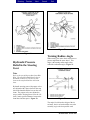
Adjust the Pressure
Relief in the Power
Steering System (Setting
the Maximum Turn
Angle)
The pressure relief in the power steering
system stops or reduces forces applied to the
axle when the wheel is moved in the fullturn position.
Use a pressure gauge to make sure t hat the
pressure drops from the maximum system
delivery pressure to a maximum of 700-1000
psi (4825-6890 kPa) BEFORE the full
turning angle is achieved.
Steering systems with mechanical stops are
adjusted when the wheels are turned to the
full right and full left turn positions. The
stop travel is set at 1/8 inch (3 m) before the
top bolt contacts the axle beam boss.
Figure 69.
Check the pressure relief if the steering arm
is damaged or the power steering gear is
serviced.
Two types of systems are used to adjust the
pressure relief:
•
•
Mechanical Stop on the Pitman Arm or
in the Assist Cylinder
Hydraulic Pressure Relief in the Power
Steering Gear
All American Front Axle
39
Directory
Previous
Previous
Next
Search
Exit
Figure 70
Figure 69
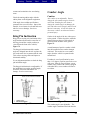
Turning Radius Angle
Hydraulic Pressure
Relief in the Steering
Gear
When turning, the inner wheel must turn at a
greater angle than the outer wheel. This
angle is the turning radius angle (often
called the Ackerman angle). Figure 71.
Note
Refer to the specified procedure from Blue
Bird. The stop bolt should always have a
minimum clearance of 1/8-inch (3 mm)
between the stop bolt and the axle beam
boss.
Hydraulic steering gears with poppet valves
are adjusted with a spacer between the stop
bolt in the knuckle and the boss on the axle
beam. The poppet valves are adjusted to
stop or reduce steering forces from t he 1/8inch (3 mm) specified distance between the
beam boss and the spacer. Figure 70.
Figure 71
The angle is built into the design of the tie
rod arms, the tie rod ends and the cross tube
assembly to give the best possible road
40
All American Front Axle
Directory
Previous
Previous
Next
Search
Exit
contact and to minimize tire wear during
turns.
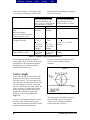
Camber Angle
Check the turning radius angle with the
radius plates on the alignment equipment.
Caution
If the angle is not within specifications,
premature tire wear will occur. Inspect the
knuckle, tie rod arms, tie rod ends and cross
tube for wear or damage. Service as
necessary.
King Pin Inclination
King pin (or steering axis) inclination is the
angle measured between the center line of
the king pin and the vertical position (as
viewed from the front of the vehicle).
Figure 72.
The king pin inclination and the camber
angle are designed into the axle to place the
tire tread center line in contact with the road.
This reduces steering effort and improves
directional stability.
Use an alignment machine to check the king
pin inclination angle.
The king pin inclination is not adjustable. If
the inclination is not at the specified angle,
check the axle beam and knuckle for
damage. Service as necessary.
Axle camber is not adjustable. Do not
change the axle camber angle or bent the
axle beam. Bending the axle beam to
change the camber angle can damage the
axle and reduce axle strength, and will void
Meritor's warranty. A bent axle beam can
also cause a vehicle accident and serious
personal injury.
Camber is the angle of the tire with respect
to the ground. Camber is positive when the
distance between the top of the wheels is
greater than the distance at the ground.
Figure 73.
A small amount of positive camber is built
into the knuckle because camber changes
with load. This results in a zero camber
angle when the vehicle is operated at the
normal load.
If camber is out of specification by more
than 1 1/2 degrees, rapid or uneven tire wear
will occur. Bias ply tires will show excess
camber easily, while with vehicles equipped
with radial tires, excess camber will not be
as evident.
Figure 73
Figure 72
All American Front Axle
The camber angle is not adjustable. The
camber angle is machined into both the axle
41
Directory
Previous
Previous
Next
Search
beam and the knuckle. If the camber angle
is not at the specified angle, check the axle
Conditions
Camber angles machined into
axles:
Hubs not installed.
Axles not installed in vehicle.
Load not applied on axle.
Camber angles of axles
equipped with hubs
Camber angles under load
Axle installed in vehicle
Exit
beam and the steering knuckle for damage.
Service as necessary.
Old Camber Specification
Ales with Assembly Dates:
No Date indicated on tag
Prior to Aug 31, 1992 (92244)
Any date with a "P" Suffix
Left Side
Right Side
+3/4°
+1/4°
Nominal
Nominal
+3/4°
(+7/16°)
or
+1 3/16°to
5/16° (final
reading)
+11/16° to 3/16° (final
reading)
+1/4°
(+7/16°)
or
+11/16° to 3/16° (final
reading)
+3/16° to 11/16° (final
reading)
New Camber Specification
Axles with Assembly Dates
On or after Sep 1, 1992
(92245) with no "P" suffix
Left and Right Sides
+1/4° Nominal
+1/4° (+7/16°)
or
+11/16° to -3/16° (final
reading)
+3/16° to -11/16° (final
reading)
Table D - Camber Angle Recommendations
Use an alignment machine to check the
camber angle. Refer to the procedure of the
manufacturer of the alignment equipment.
The table above gives the specification
Meritor builds into the axle.
If caster is too much, steering effort will
increase or may amplify a shimmy
condition.
Caster Angle
Caster is the forward or rearward tilt of the
king pin center line when viewed from the
side of the vehicle. The caster angle is the
angle from the vertical position to the center
line of the king pin. If the top of the king
pin axis is toward the rear of the vehicle, the
caster is positive. A slight positive caster
creates a self-aligning action that helps to
stabilize the vehicle after turning and
stabilizes it for driving straight ahead.
Figure 74.
Always use an alignment machine to check
the caster angle. When checking caster,
refer to the instructional procedures from the
alignment equipment manufacturer.
42
Figure 74
The caster angle is controlled by tapered
shims installed under the leaf springs.
Adjust caster according to Blue Bird
specifications and procedures.
All American Front Axle
Directory
Previous
Previous
Next
Meritor recommends a caster setting of +1
degree to +2 1/2 degrees for vehicles with
manual steering and +2 degrees to +4 1/2
degrees for vehicles with power steering.
Adjust the Toe-In
Toe is the relationship of the distance
between the front of the front tires and the
rear of the front tires.
When the front distance is less than the rear
distance, the wheels are "toed in". Toe-in is
designed into the vehicle to counteract the
tendency of the tires to toe-out when the
vehicle is driven.
Incorrect toe-in will result in rapid tire wear.
Toe-in specifications:
•
•
Unloaded vehicles 1/16 inch (1.587 m)
+1/31 inch (0.794 mm)
Loaded vehicles 1/32 inch (0.794 mm)
+1/32 inch (0.794 mm).
Caution
Most tire wear is caused by incorrect toe
settings. Do not change camber or caster
settings to correct tire wear problems. If the
axle assembly is bent to change caster or
camber, the strength of the axle is reduced
and the warranty is voided. An axle
damaged by bending may cause a vehicle
accident and result in serious personal
injury.
Search
Exit
Jacks can slip and fall over. Serious
personal injury can result.
2. Use jacks to raise vehicle so that front
tires are off the ground. Support the
front axle with safety stands.
3. Use paint or chalk to mark the center
area of both front tires around t he
complete outer surface of the tire.
4. Place the pointers of a trammel bar on
the marks of each tire. Rotate the tires.
Make sure a straight line is marked on
the outer surface of the tire.
Note
Do not measure toe-in with the front axle in
the raised position. The weight of the
vehicle must be on the front axle when toe-in
is measured.
5. Lower the vehicle to the floor. Move
the vehicle forward and backward 10
feet (3 meters).
6. Place the trammel bar at the back of the
tires. Raise the pointers so that the
pointers are level with the spindles.
Align the pointers with the marks on the
tires. Measure and record the distance
between the pointers.
7. Place the trammel bar at the front of the
tires. Raise the pointers so that the
pointers are level with the spindles.
Align the pointers with the marks on the
tires. Measure and record the distance
between the pointers. Figure 75.
1. Make sure the vehicle is on a level
surface. Place blocks behind the rear
wheels to prevent the vehicle from
moving. Raise the vehicle so that the
front tires are off the floor.
Warning
Park the vehicle on a level surface. Block
the wheels to prevent moving. Support the
vehicle with safety stands. Do not work
under a vehicle supported only by jacks.
All American Front Axle
Figure 75
43
Directory
Previous
Previous
Next
Search
Exit
8. To obtain the toe measurement, subtract
the distance reading between the front of
the tires from the distance reading
between the back of the tires. Figure 76.
9. If the toe measurement is not at the
specified distance, refer to the following
procedure.
a. Loosen the tube clamp nut and bolt
on each end of the cross tube.
b. Turn the cross tube until the
specified toe-in distance is obtained.
c. The threaded portion of the tie rod
end must be installed into the cross
tube beyond the point where the
tube slot stops.
d. Tighten the nut and bolt on each end
of the cross tube to the specified
torque.
10. Repeat Steps 1-8 to check the toe-in
dimension.
Figure 76
Diagnostics
Warning
To prevent serious eye injury, always wear
safe eye protection when you perform
vehicle maintenance or service.
Front Non-Drive Steering Axle Diagnostic Chart
The following chart is for troubleshooting front non-drive steering axle conditions.
Condition
Cause
Correction
1. Place specified air
Tires wear out quickly 1. Tires have incorrect air pressure.
pressure in tires.
or have uneven tire
2. Tires out of balance.
2. Balance or replace tires.
tread wear.
3. Incorrect tandem axle alignment.
3. Align tandem axles.
4. Incorrect toe-in setting.
4. Adjust toe-in specified
5. Incorrect steering arm geometry.
setting.
6. Excessive wheel end play exists.
5. Service steering system as
necessary.
6. Readjust wheel bearings.
1. Repair power steering
Vehicle is hard to
1. Power steering system pressure
system.
steer.
low.
2. Assemble steering gear
2. Steering gear linkage not
correctly.
assembled correctly.
3. Steering linkage needs lubrication. 3. Lubricate steering linkage.
4. Replace king pins.
4. King pins binding.
5. Service steering system as
5. Incorrect steering arm geometry.
necessary.
6. Caster out of adjustment.
6. Adjust caster as necessary.
7. Tie rod ends hard to move.
7. Replace tie rod ends.
8. Worn thrust bearing.
8. Replace thrust bearing.
44
All American Front Axle
Directory
Previous
Previous
Next
Search
Exit
Tie rod ends are worn
and require
replacement.
1. Tie rod ends require lubrication.
2. Severe operating conditions.
3. Damaged boot on tie rod end.
Bent or broken cross
tube, tie rod end ball
stud, steering arm or
tie rod end.
(Component requires
replacement.)
1. Too much pressure in t he power
steering, pressure exceeds OEM
specification.
2. Power steering system cut-off
pressure, out of adjustment.
3. Vehicle operated under severe
conditions.
4. Add-on type of power steering
system not installed correctly.
5. Steering gear overtravel poppets
improperly set or malfunctioning.
6. Axle stops improperly set.
Worn or broken
steering ball stud.
1. Drag link fasteners tightened
higher than OEM specified.
2. Lack of lubrication or incorrect
lubricant.
3. Power steering stops out-ofadjustment.
1. Worn or missing seals and
gaskets.
2. Incorrect lubricant.
3. Axle not lubricated at scheduled
frequency.
4. Incorrect lubrication procedures.
5. Lubrication schedule does not
match operating conditions.
Worn king pins and
king pin bushings.
Vibration or shimmy
of front axle during
operation.
1. Caster out-of-adjustment.
2. Wheels and/or tires out-ofbalance.
3. Worn shock absorbers.
1. Lubricate ends of cross
tube. Make sure
lubrication schedule is
followed.
2. Increase frequency of
inspection and lubrication
intervals.
3. Replace boot.
1. Adjust power steering
system to specified
pressure.
2. Adjust power steering
system to specified
pressure.
3. Make sure vehicle is
operated correctly.
4. Correctly install add-on
power steering system.
5. Check for proper
operation or adjust
overtravel of poppets to
OEM specification.
6. Set axle stops to OEM
specification.
1. Tighten drag link fasteners
to specified torque.
2. Lubricate linkage with
specified lubricant.
3. Adjust stops to specified
dimension.
1. Replace seals and gaskets.
2. Lubricate axle with
specified lubricant.
3. Lubricate axle at
scheduled frequency.
4. Use correct lubrication
procedures.
5. Change lubrication
schedule to match
operating conditions.
1. Adjust caster.
2. Balance or replace wheels
and/or tires.
3. Replace shock absorbers.
Warning
To prevent serious eye injury, always wear safe eye protection when you perform vehicle
maintenance or service.
All American Front Axle
45
Directory
Previous
Previous
Next
Search
Exit
Group Number
Typical Vocations
Vehicle Build
Typical Operation
Conditions
2
Fire and rescue, city
delivery, inner city
coach, heavy haul,
school bus, motor
home, transit coach
Logging, oil field,
construction, heavy
haul, yard tractor
(highway licensed),
residential refuse
After July 1, 1996
Before July 1, 1996,
use Group Number 3
Lower mileage
operation (less than
50,000 miles/year (80
500 km/year))
ALL
Low mileage
operation (less than
25,000 miles/year
(40/250 km/year))
3
Table E: Vocational Groups
Lubrication, Inspection and Maintenance Schedule
Service Intervals
48
hrs
Component
Tie Rod
Ends
Group 2
Group 3
Inspect the
Tie Rod
Assembly
for
Movement
Group 2
Group 3
Tie Rod
End Shop
Inspection
Ball Stud on
Steering
Arms
Easy Steer
Plus™ Axle
Ball Studs
Sealed Axle
Ball Studs
Drag Link
King Pins
and
Bushings
Steering
Arm Bolts
Thrust
Bearings
46
5,000
miles/
100
hrs
8050
km
First
6,000
miles of
operation
10 000
km
10,000
miles
20,000
miles
36,000
miles
40,000
miles
50,000
miles
100,000
miles
200,000
miles
16 100
km
32 200
km
58 000
km
64 000
km
80 500
km
160 000
km
320 000
km
I
L*
I, L*
I
I
L*
I
I
L*
L*
I
L*
All American Front Axle
Directory
Previous
Previous
Steering
Knuckle
Vertical
End Play
Inspection
Group 2
Group 3
Upper and
Lower King
Pin
Bushings
for Wear
Group 2
Group 3
Draw Key
Nuts
New vehicle
In-service
vehicle
Sealed Hub
Unit
Inspection
Next
Search
Exit
I
I
I
I
T
T
I
I=Inspect
L=Lubricate
T=Tighten to Specifications.
*If power washers are used during vehicle cleaning operations, lubrication intervals need to be adjusted.
Frequent power washed vehicles will require more frequent lubrication.
Table F: Lubrication, Inspection and Maintenance Schedule
Component Greasing Grease
Interval
Meritor
NLGI
Specification Grade
Grease Type Outside
Temperature
King Pins and
Bushings,
Thrust
Bearings, Ball
Studs on
Steering Arm,
Tie Rod Ends,
and Drag Link
Truck Hub
Unit
MultiPurpose
Grease
O-617-A
Or
O-617-B
1
or
2
Lithium 12Hydroxystearate
or Lithium
Complex
Unit
Sealed for
life of
component
NONE
Do Not
lubricate
100,000
miles (160
000
kilometers)
or once a
year,
whichever
comes first
No Lube to
Hub
Refer to the
grease
manufacturer's
specifications
for the
temperature
service limits
Table G: Front Non-Driving Axle Greasing Intervals and Specifications
All American Front Axle
47
Directory
Previous
Previous
On-Highway
Operation Intervals
Check
Oil
Level
Petroleum
Oil Change
1,000
miles
(1600
kilo
meters)
Whichever
comes first:
Seals
replaced
Brakes
relined
100,000
miles
(160 000
kilometers)
Next
Off-Highway
Operation Intervals
PetroCheck Oil
leum
Level
Oil
Change
1,000 miles Which(1600
ever
kilometers) comes
first:
Seals
replaced
Brakes
relined.
Once a
year.
Once a
year
Search
Exit
Outside Temperature
Meritor
Specs
Military
Specs
Oil
Description
O-76A,
Gear Oil
O-76D,
Gear Oil
O-76E,
Gear Oil
O-76J,
Gear Oil
Heavy
Duty
Engine
Oil
MIL-L2105-D
MIL-L2105-D
MIL-L2105-D
MIL-L2105-D
MIL-L2104-B,
C, D or E
Heavy
Duty
Engine
Oil
MIL-L2104-B,
C, D or E
GL-5, SAE
85W/140
GL-5, SAE
80W/90
GL-5, SAE
75W/90
GL-5, SAE
75W
API –CD,
CE, SF or
SG
SAE 40 or
50 (1)
API –CD,
CE, SF or
SG
SAE 30 (2)
F°
C°
Min
Max
Min
Max
10
None
12
None
-15
None
-26
None
-40
None
-40
None
-40
36
-40
2
10
None
12
None
-15
None
-26
None
Table H: Wheel End Oil Change Intervals and Specifications
(1) Current designations are acceptable. Multi-weight engine oils are acceptable if the SAE rating ends in
a 40 or 50.
(2) Current designations are acceptable. Multi-weight engine oils are acceptable if the SAE rating ends in
a 30.
Lubrication
Tie Rod End Lubrication
This procedure refers to all tie rod ends on
Meritor non-drive steering axles.
1. Turn the vehicle wheels straight ahead.
Figure 77.
2. Wipe the zerk fitting clean with shop
towels. Figure 78.
3. Wipe the seal/boot clean with shop
towels.
4. Attach a grease gun to the zerk fitting.
Either a hand or air pressure grease gun
is acceptable. If using air pressure, do
not exceed 150 psi (1035 kPa). Figure
79.
5. Discolored old grease should come out
of the purge holes near the boot crimp or
bellows area (typically three or more
places). Figure 80.
48
6. If the tie rod end is designed for lube
service and it does not accept grease:
a. Remove the zerk fitting.
b. Inspect the threaded zerk fitting hole
in the tie rod end and remove any
obstructions.
c. Install a new zerk fitting.
d. Continue the lubrication procedure.
Note
Synthetic lubes are not yet approved for tie
rod end lubrication.
7. Apply grease until all old grease is
purged from the boot.
All American Front Axle
Directory
Previous
Previous
Next
Search
Exit
Figure 77
Figure 79
Figure 78
All American Front Axle
49
Directory
Previous
Previous
Next
Search
Exit
Figure 80
King Pins
On conventional front axles, the grease
fittings are on the side of the knuckle.
Straight King Pins
Warning
Note
This procedure applies to 901, 903, 910,
935, 952 and 970 front conventional axles.
Refer to the identification tag on the front of
the axle beam.
50
Park the vehicle on a level surface. Block
the wheels to prevent the vehicle from
moving. Support the vehicle with safety
stands. Do not work under a vehicle
supported only by jacks. Jacks can slip and
fall over. Serious personal injury can result.
All American Front Axle
Directory
Previous
Previous
Next
1. Lift the vehicle so that the tires are off
the ground. The front tires should be off
the ground when the king pins are
lubricated. Support the vehicle with
safety stands. Place blocks in front and
behind the rear wheels to keep the
vehicle from moving. Set the parking
brake.
2. Lubricate the king pins through the top
and the bottom king pin cap grease
fittings. Figure 81.
3. Apply lubricant until new lubricant
comes from between the upper shim
pack and thrust bearing seal.
4. Lower the vehicle so that the wheels
touch the ground.
5. Apply lubricant to the bottom fitting
until new lubricant purges and fills the
thrust bearing.
Search
Exit
Figure 81
Grease-Lubricated
Wheel Bearings
Note
This procedure applies to hubs with greaselubricated wheel bearings.
Figure 81
Ball Studs on Steering Arm,
the Tie Rod Arm Ends and
the Drag Link
1. Remove the tire and wheel assembly.
Remove and disassemble the hub. Refer
to the section on "Wheel Ends".
2. Remove the old lubricant from all parts.
Discard the seals. Inspect the wheel
bearings for wear or damage. Replace
worn or damaged bearings. Refer to
"Preparing Parts for Assembly" section.
3. Force the specified lubricant from the
large end of the cones into the cavities
between the rollers and cage. Pack the
hub between the bearing cups with
lubricant to the level of the small
diameter of the cups. Figure 82.
1. Make sure the tires touch the ground.
DO NOT RAISE THE VEHICLE.
2. Clean off all grease fittings prior to
lubrication.
3. Apply lubricant until new lubricant
comes from the boot. Figure 81.
All American Front Axle
51
Directory
Previous
Previous
Next
Search
Exit
Figure 82
4. Install the inner and outer bearing cones
into the cups in the hubs. The bearing
cups must be pressed tight against the
shoulder in the hubs.
5. Install new wheel seals in the hubs.
6. Install the hub and the wheel and tire
assembly. Install the outer wheel
bearing cone in the hub. Install the
adjusting nut.
7. Adjust the wheel bearings. Refer to
Section entitled "Check and Adjust the
Wheel Bearings".
Oil-Lubricated Wheel
Bearings
Note
Figure 83
Inspection and
Maintenance
Inspection Tools
Before performing an inspection of axle
components, make sure the proper tools are
available. Using the proper tools will ensure
safety and provide the most accurate results.
Check for the following tools:
•
•
•
•
•
•
Dial Indicator
Tire Blocks
Jack
Safety Stands
Pry Bar
Torque Wrench
This procedure applies to hubs with oillubricated wheel bearings.
Check the level on the cap. If the oil level is
not at the specified level on the cap, remove
the fill plug. Add the specified oil until the
oil is at the specified level. Figure 83.
52
Inspection
Caution
The repair or reconditioning of front axle
components is not allowed. Meritor
recommends replacing damaged or out-ofspecification components. All major
components are heat treated and tempered.
The components cannot be bent, welded,
heated or repaired in any way without
reducing the strength or life of the
component and voiding the warranty and
All American Front Axle
Directory
Previous
Previous
Next
Search
Exit
may cause a vehicle accident which can
result in serious personal injury.
Check the following during an inspection.
Fasteners. Make sure all fasteners are
tightened to the specified torque. Use a
torque wrench to check the torque in a
tightening direction. As soon as the fastener
starts to move, record the torque. Correct if
necessary. Replace any worn or damaged
fasteners.
Wear and Damage. Inspect the parts of the
axle for wear and damage. Look for bent or
cracked parts. Replace all worn or damaged
parts.
Pivot Points. Make sure looseness does not
exist at the pivot points. Make sure the
pivot points are lubricated.
Operation. Make sure all the parts move
freely through the complete turning radius.
Tire Wear. Inspect the tires for wear
patterns that indicate suspension damage or
misalignment.
Steering Arm Bolts. Check torque on Easy
Steer Plus™ MFS 10-2015 and MFS 122015 axles every 200,000 miles (320 000
km). Refer to the "Checking Steering Arm
Bolts" in this section.
Checking Draw Key Nuts
Tighten the draw key nuts from 30 to 45 lbft (41-61 N•m) at the following intervals.
Figure 84.
•
After the first 6,000 miles (10 000 km)
of new vehicle operation.
•
Every 36,000 miles (58 000 km) of
operation.
All American Front Axle
Figure 84
Checking Steering
Knuckle Vertical End
Play
1. Place blocks in front and behind the rear
wheels to prevent the vehicle from
moving.
Warning
Park the vehicle on a level surface. Block
the wheels to prevent the vehicle from
moving. Support the vehicle with safety
stands. Do not work under a vehicle
supported only by jacks. Jacks can slip and
fall over. Serious personal injury can result.
2. Use a jack to raise the vehicle until the
front wheels are off the ground. Support
the front axle with safety stands.
3. Install a dial indicator so that the base is
on the I-beam and that the tip is on the
top knuckle cap. Figure 85.
4. Place a pry bar between the boss for the
tie rod arm and the I-beam. Push the
knuckle to the bottom of vertical travel.
Figure 86.
53
Directory
Previous
Previous
Next
Search
Exit
Note
If one bushing requires replacement, then
replace both bushings in the knuckle.
5. Set the dial indicator on "zero" (0).
6. Use the pry bar to push the knuckle
upward. Record the reading on the dial
indicator.
The reading must be 0.001- to 0.025inch (0.025-0.635 mm) for new or
rebuilt axles and 0.001- to 0.065-inch
(0.025-1.650 mm) for axles in service.
Figure 86.
If the reading is "zero" (0), remove the
knuckle and remove shims from the
shim pack.
If the reading is more than the maximum
specification, remove the knuckle and
add shims to the shim pack.
Figure 86
Checking the Upper and
Lower King Pin Bushings
for Wear
1. Place blocks in front and behind the rear
wheels to prevent the vehicle from
moving.
Warning
Park the vehicle on a level surface. Block
the wheels to prevent the vehicle from
moving. Support the vehicle with safety
stands. Do not work under a vehicle
supported only by jacks. Jacks can slip and
fall over. Serious personal injury can result.
Figure 85
54
2. Use a jack to raise the vehicle until the
wheels are off the ground. Support the
vehicle with safety stands.
3. Check the upper king pin bushing for
wear. Install a dial indicator so that the
base is on the I-beam and that the tip is
against the side of the top of the
knuckle. Figure 87.
4. Set the dial indicator to "zero" (0).
All American Front Axle
Directory
Previous
Previous
Next
Search
Exit
Note
If one bushing must be replaced, replace
both bushings in the knuckle.
5. Move the top of the tire side-to-side
towards and away from the vehicle. If
the dial indicator moves a total of 0.010inch (0.254 mm), the upper bushing is
worn or damaged. Replace both
bushings. Figure 87.
Figure 88
Inspect the Tie Rod Ends
1. Park the vehicle with the steering
wheels in the straight-ahead position.
Figure 89.
Figure 87
6. Check the lower king pin bushing.
Install a dial indicator so that the base is
on the I-beam and that the tip is against
the side of the bottom of the knuckle.
Figure 88.
7. Set the dial indicator on "zero" (0).
8. Move the bottom of the tire side-to-side
towards and away from the vehicle. If
the dial indicator moves a total of 0.010inch (0.2254 mm), the lower bushing is
worn or damaged. Replace both
bushings. Figure 88.
Figure 89
All American Front Axle
55
Directory
Previous
Previous
Next
2. Place blocks in front and behind the rear
wheels to prevent the vehicle from
moving. Set the parking brake.
3. Remove dirt and grease from the tie rod
end seals.
4. Place indicator base on the bottom of the
tie rod arm.
5. Place the indicator tip near the ball stud
center (grease fitting) of the tie rod end.
Figure 90.
Search
Exit
Inspect the Tie Rod
Assembly for Movement
This procedure applies to all tie rod
assemblies.
To perform this inspection, the entire system
must be "unloaded" (i.e., the front end of the
vehicle must be raised and supported with
stands).
Caution
Do not grease the tie rod assembly before
performing the inspection. Doing so may
provide inaccurate results.
Replace the entire tie rod end if the boot is
torn or missing. Do not replace the boot
only.
Figure 90
6. Set the dial indicator on "zero" (0).
Caution
Check the tie rod end play by hand. Do not
use a pry bar. If a pry bar is used, readings
from the dial indicator will not be accurate.
7. Move the tie rod and cross tube
assembly up and down by hand.
8. Record the dial indicator reading. If the
dial indicates a reading of more than
0.060-inch (1.52 mm), tie rod end
replacement is required.
9. Place the dial indicator on the tie rod
end assembly at the opposite side of
vehicle and repeat Steps 1 through 8.
56
1. Place blocks in front of and behind the
vehicle's rear wheels. Using the bottom
of the I-beam or frame rails, raise the
front end off the ground, and support
with stands.
2. With the engine off, turn wheels from
full left to full right, and then return to
the straight-ahead position. (This step
will require more force for vehicles with
power steering turned off.)
3. Check that the boot is in place and
completely installed over the tie rod end.
Note
The boot may be missing completely or may
not completely cover the ball joint.
4. Check for cracking or tears in the boot.
Also, check the boot seals for damage.
Replace the entire rod end if the boot is
damaged. Figure 91.
All American Front Axle
Directory
Previous
Previous
Next
Search
Exit
Figure 91
Figure 92
Warning
A cotter pin must be installed through the tie
rod end with the tie rod end nut tightened to
torque specification to securely attach the
tie rod. Loss of the cotter pin will allow the
tie rod end nut to become loose and affect
vehicle steering and possibly result in loss of
steering control.
7. Check that zerk fittings are installed.
Replace a damaged zerk fitting with a
new one. Some tie rod ends are nongreaseable and will not have zerk
fittings. Do not install fitting if tie rod
end is non-greaseable type.
Caution
5. Check that the tie rod nut is installed
and secured with a cotter pin. If the
cotter pin is missing, check the nut
torque specification and then install a
new cotter pin. Always tighten tie rod
nut to specified torque when setting the
cotter pin.
Do not use the following items or methods to
check for movement of the tie rod assembly.
Damage to components can result if:
•
•
•
Caution
A crow bar, pickle fork or 2 x 4 is used.
A tool instead of your hands is used to
grasp the cross tube assembly that
results in cross tube damage.
Pressure or force is applied to the ends
or the joints of the assembly.
The tires are rocked either with the
vehicle on the ground or with the wheels
raised.
The tie rod ends must be at the end of the
cross tube slot to ensure adequate thread
engagement.
•
6. Check that the tie rod end is threaded
correctly into the cross tube and
engaged deeper than the end of the cross
tube slot. The tie rod end must be
visible the entire length of the cross tube
slot. Figure 92.
8. By hand or using a pipe wrench with
jaw protectors to avoid gouging the
cross tube, rotate the cross tube toward
the front of the vehicle and then toward
the rear. After rotating, center the cross
tube. If the cross tube will not rotate in
either direction, replace both tie rod
ends.
9. Position yourself directly below the ball
stud socket. Using both hands, grab the
assembly end as close to the socket as
All American Front Axle
57
Directory
Previous
Previous
Next
possible (no more than 6 inches or 152.4
mm). Apply hand pressure
(approximately 100 pounds) vertically
(up and down) in a push-and-pull
motion several times. Check for any
movement or looseness at both tie rod
end locations.
10. If there is any movement in the tie rod
assembly, replace both tie rod ends.
Tie Rod End Shop
Inspection
Caution
Replace the entire tie rod end if the boot is
torn or missing. Do not replace the boot
only.
Search
Exit
4. If any movement is detected at one tie
rod end, replace it and the other tie rod
end. Always replace tie rod ends in
pairs, even if only one tie rod is found
damaged.
Warning
Do not attempt to straighten a bent cross
tube. Damage to the axle can result. Be
certain to replace any cross tube with an
original equipment cross tube (with the
same length, diameter and threads).
5. Inspect the cross tube and clamps for
damage. Figure 93.
•
•
1. Check the tie rod boot for cracks, tears
or other damage. All tie rod ends with a
damaged boot require that the entire tie
rod end be replaced. Figure 91.
2. Grab by hand (or using a pipe wrench
with jaw protectors to avoid gouging the
cross tube) and slightly rotate the cross
tube toward the front of the vehicle and
then slightly toward the rear. After this
movement, check in both directions,
centering the cross tube between the
stop positions. If the cross tube will not
rotate in either direction, replace both tie
rod ends.
3. Position yourself directly below the ball
stud socket. Using both hands, grab the
end as close to the socket as possible (no
more than 6 inches or 152.4 mm from
the end). Firmly apply hand pressure
(approximately 100 pounds) in a vertical
push and pull motion several times.
When moving the assembly, check for
any movement at both tie rod ends.
Warning
If any movement is detected by hand,
replace the worn components with new
components before releasing the vehicle
back into service.
58
•
Replace the cross tube if it is
cracked or bent.
Replace the clamps if they are
damaged.
Replace the entire cross tube
assembly if either clamp is welded
onto it.
Figure 93
6. Check for proper installation of the tie
rod end clamp to the cross tube. Be
certain that tie rod ends are threaded in
the cross tube past the clamps and the
slots at the cross tube ends.
7. Check that zerk fittings are installed.
Replace damaged zerk fittings. Replace
damaged zerk fittings. Figure 94.
Refer to Table E.
All American Front Axle
Directory
Previous
Previous
Next
Some tie rod ends have no zerk fittings
because they are not greaseable. Do not
install a zerk fitting on a non-greaseable
design tie rod end.
8. Check that the cotter pin is in place.
Replace if missing. Tighten the tie rod
end nut to the specified torque and then
insert the cotter pin through the
castellated nut and the hole in the tie rod
end.
Search
Exit
2. Drive-on ramps may also be used.
Observe all of the manufacturer's safety
recommendations.
Tie Rods
Effect of Tie Rod End Wear on
Steering Linkage
Unless tie rod end wear becomes excessive,
a safe steering linkage is maintained.
However, tie rod end wear can affect
uniform steering control and, ultimately,
wear to the front tires.
Detecting Tie Rod End Wear During
Vehicle Operation
Figure 94
A driver may not always detect a loose tie
rod end condition during vehicle travel
conditions. This is why it is important to
inspect tie rod ends for wear and allowable
movement at regular intervals. Refer to
Table E for inspection intervals
Tie Rod Service Tips
If available, a service pit is recommended
for tie rod inspection and maintenance. If a
service pit is not available, use the following
method.
1. Use jacks to raise the vehicle using the
following.
a. The vehicle must be on a level
surface.
b. Put blocks under the wheels not
being raised to keep the vehicle
from moving.
c. Raise the vehicle so that the area to
be serviced is off the ground.
Support the vehicle with safety
stands.
d. Inspect and lubricate the tie rod ends
as specified in Table E.
All American Front Axle
Tie Rod End Wear
It is imperative that inspection and
maintenance is performed at the
recommended intervals to minimize the
impact of tie rod end wear. Tie rod end
wear occurs over time, under normal
operating conditions. As wear occurs, the
preload bearings inside each tie rod end
provide less resistance. Excessive tie rod
end wear will affect steering and contribute
to premature wear of the tires and other axle
components. Figure 95.
59
Directory
Previous
Previous
Next
Search
Exit
Tighten the nuts that hold the draw keys on
the side of the knuckle to 30-45 lb-ft (41-61
N•m) at the following times. Figure 96.
•
•
After the first 6,000 miles (10 000 km)
of new vehicle operation.
Every 36,000 miles (58 000 km) of
operation.
Figure 96
Checking Steering Arm
Bolts
Warning
Figure 95
Take care when you use Loctite® to avoid
serious personal injury. Follow the
manufacturer's instructions to prevent
irritation to the eyes and skin.
Note
Tightening Draw Key
Nuts
Note
This procedure applies to all except 901,
903 and 970 Series axles. These axles do
not utilize a draw key. Refer to the
identification tag on the front of the axle
beam.
60
This procedure applies to ALL axles
included in this manual.
Check steering arm bolts for minimum 300
lb-ft (406 N•m) torque. If steering arm bolt
torque has fallen below 300 lb-ft (406 N•m),
remove bolts, clean all threads, and install
new Loctite®. Tighten bolts from 300 to
450 lb-ft (406-610 N•m) torque. Check
steering arm bolt torque every 200,000 miles
(320 000 km) or 24 months.
All American Front Axle
Directory
Previous
Previous
Next
Note
Old Loctite® must be removed from bolt
threads and internal threads of knuckle
itself. Reapply new Loctite® 680 (Meritor
#2297-K-5523).
Search
Exit
Torque Specifications
Warning
To prevent serious eye injury, always wear
safe eye protection when you perform
vehicle maintenance or service.
Front Non-Drive Axles with Conventional Wheel Ends
Figure 97
All American Front Axle
61
Directory
Previous
Previous
Next
Search
Exit
Front Axle with Conventional Wheel Ends Torque
Specifications
Item
Description
Size
1
Steering Arm to Drag Link Nut
2
3
Knuckle Cap Screw
Steering Arm to Knuckle Nut
5/8"—16
5/8"—18
3/4"—16
7/8"—14
5/16"—18
7/8"—14
1"—14
1-1/8"—12
1-1/4"—12
1-1/2"—12
4
5
6
7
8
Draw Key Nut
3/4" Stop Screw Adapter
1/2" Stop Screw Lock/Jam Nut
3/4" Stop Screw Lock/Jam Nut
Tie Rod Arm to Tie Rod End Nut
7/16"—20
9
Cross Tube Clamp Nut
10
Tie Rod Arm to Knuckle Nut
7/8"—14
1"—14
1-1/8"—12
1-1/4"—12
5/8"—11
3/4"—10
7/8"—14
1"—14
1-1/8"—12
1-1/4"—12
1-1/2"—12
lb—ft
Torque Range
N•m
60—115
60—115
90—170
160—300
20—30
250—450
390—725
550—1025
775—1450
1350—2525
30—45
65—115
50—75
65—85
160—300
250—450
350—650
500—675
40—60
155—175
250—450
390—725
550—1025
775—1450
1350—2525
82—155
92—155
123—230
217—407
28—40
339—610
529—982
746—1389
1051—1965
1831—3423
41—61
88—155
68—101
88—115
217—406
339—610
475—881
678—915
55—81
211—237
339—610
529—982
746—1389
1051—1965
1831—3423
Table I—Front Axle with Conventional Wheel Ends
62
All American Front Axle
Directory
Previous
Previous
Next
Search
Exit
Special Tools
Description
Kent-Moore
Tool Number
(1)
Owatonna Tool
Number (2)
Snap-On® Tool
Number (3)
References
King Pin Remover
4240
4240
20 Ton:
CG430HYB
King Pin Bushing
Service Kit
Basic Service Kit
FF- and FG- Series
Kits
FL-Series Kit
(4)
"Disassembly"
Section
"Disassembly"
Section
PT 4375-A
PT 4370-10
PT 4370-20
Table J—Special Tools
(1) Order Kent-Moore tools from: Kent-Moore, 28635 Mound Road, Warrren, MI 48092
(2) Order Owatonna tools from: OTC Tool and Equipment Division, 655 Eisenhower Drive, Owatonna,
MN 55060
(3) See your local Snap-On® dealer.
(4) Use Basic Service Kit along with the correct axle series kit.
Back to Top
All American Front Axle
63