1
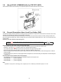
ORDER NO.DSC1203010CE
B26
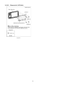
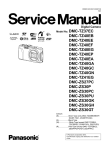
Digital Camera
Model No. DMC-FT4EB
DMC-FT4EE
DMC-FT4EF
DMC-FT4EG
DMC-FT4EP
DMC-FT4GC
DMC-FT4GN
DMC-TS4P
DMC-TS4PC
DMC-TS4PU
DMC-TS4GH
DMC-TS4GD
Colours
(A)....................Blue Type (Except DMC-FT4EE/EF)
(D)....................Orange Type
(S)....................Silver Type (Except DMC-FT4EF, DMCTS4GD/PC)
(K)....................Black Type (Except DMC-FT4EE, DMCTS4GD/GH)
© Panasonic Corporation 2012.
Unauthorized copying and distribution is a violation
of law.
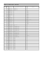
TABLE OF CONTENTS
PAGE
1 Safety Precautions -----------------------------------------------3
1.1. General Guidelines ----------------------------------------3
1.2. Leakage Current Cold Check ---------------------------3
1.3. Leakage Current Hot Check (See Figure 1)---------3
1.4. How to Discharge the Capacitor on Flash
CON P.C.B. --------------------------------------------------4
2 Warning --------------------------------------------------------------5
2.1. Prevention of Electrostatic Discharge (ESD)
to Electrostatic Sensitive (ES) Devices ---------------5
2.2. How to Recycle the Lithium Ion Battery (U.S.
Only)-----------------------------------------------------------5
2.3. Caution for AC Cord (For EB/GC/GH) ----------------6
2.4. How to Replace the Lithium Battery -------------------7
3 Service Navigation------------------------------------------------9
3.1. Introduction --------------------------------------------------9
3.2. Air-leak test (inspection)----------------------------------9
3.3. Replacing the waterproof packing (waterproof
seal) -----------------------------------------------------------9
3.4. Lens Unit -----------------------------------------------------9
3.5. About IC9301 (COMPASS) [On the TOP FPC
UNIT] -------------------------------------------------------- 10
3.6. General Description About Lead Free Solder
(PbF) -------------------------------------------------------- 10
3.7. How to Define the Model Suffix (NTSC or PAL
model)------------------------------------------------------- 11
4 Specifications ---------------------------------------------------- 15
5 Location of Controls and Components------------------ 20
6 Service Mode ----------------------------------------------------- 22
6.1. Error Code Memory Function ------------------------- 22
6.2. ICS (Indication of additional Camera Settings
when picture was taken) function -------------------- 25
7 Troubleshooting Guide---------------------------------------- 27
7.1. Service and Check Procedures ---------------------- 27
7.2. Air-leak Test ----------------------------------------------- 30
7.3. Checking Method of GPS failure --------------------- 31
7.4. Checking Method of compass, altimeter, &
barometer -------------------------------------------------- 32
8 Service Fixture & Tools --------------------------------------- 36
8.1. Service Fixture and Tools ------------------------------ 36
8.2. When Replacing the Main P.C.B. -------------------- 37
8.3. Service Position ------------------------------------------ 37
9 Disassembly and Assembly Instructions --------------- 38
9.1. Disassembly Flow Chart-------------------------------- 38
9.2. P.C.B. Location ------------------------------------------- 38
9.3. Disassembly Procedures------------------------------- 39
10 Measurements and Adjustments -------------------------- 48
10.1. Introduction ------------------------------------------------ 48
10.2. Before Disassembling the unit ------------------------ 48
10.3. Details of Electrical Adjustment----------------------- 50
10.4. After Adjustment------------------------------------------ 53
11 Maintenance ------------------------------------------------------ 54
11.1. Cleaning Lens and LCD Panel ----------------------- 54
12 Block Diagram --------------------------------------------------- 55
12.1. Overall Block Diagram ---------------------------------- 55
12.2. System Control Block Diagram ----------------------- 56
12.3. Video/Audio Signal Process Block Diagram------- 57
12.4. Sensor Block Diagram ---------------------------------- 58
12.5. Lens Drive Block Diagram ----------------------------- 59
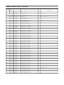
PAGE
12.6. Power Block Diagram----------------------------------- 60
13 Wiring Connection Diagram -------------------------------- 61
13.1. Interconnection Schematic Diagram ---------------- 61
2
1 Safety Precautions
1.1.
General Guidelines
1.3.
1. IMPORTANT SAFETY NOTICE
There are special components used in this equipment
which are important for safety. These parts are marked by
2.
3.
4.
5.
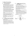
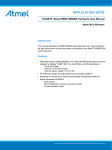
1. Plug the AC cord directly into the AC outlet. Do not use
an isolation transformer for this check.
2. Connect a 1.5kΩ, 10 W resistor, in parallel with a 0.15μF
capacitor, between each exposed metallic part on the set
and a good earth ground, as shown in Figure 1.
3. Use an AC voltmeter, with 1 kΩ/V or more sensitivity, to
measure the potential across the resistor.
4. Check each exposed metallic part, and measure the
voltage at each point.
5. Reverse the AC plug in the AC outlet and repeat each of
the above measurements.
6. The potential at any point should not exceed 0.75 V RMS.
A leakage current tester (Simpson Model 229 or
equivalent) may be used to make the hot checks, leakage
current must not exceed 1/2 mA. In case a measurement
is outside of the limits specified, there is a possibility of a
shock hazard, and the equipment should be repaired and
rechecked before it is returned to the customer.
in the Schematic Diagrams, Circuit Board Layout,
Exploded Views and Replacement Parts List. It is
essential that these critical parts should be replaced with
manufacturer's specified parts to prevent X-RADIATION,
shock fire, or other hazards. Do not modify the original
design without permission of manufacturer.
An Isolation Transformer should always be used during
the servicing of AC Adaptor whose chassis is not isolated
from the AC power line. Use a transformer of adequate
power rating as this protects the technician from
accidents resulting in personal injury from electrical
shocks. It will also protect AC Adaptor from being
damaged by accidental shorting that may occur during
servicing.
When servicing, observe the original lead dress. It a short
circuit is found, replace all parts which have been
overheated or damaged by the short circuit.
After servicing, see to it that all the protective devices
such as insulation barriers, insulation papers shields are
properly installed.
After servicing, make the following leakage current
checks to prevent the customer from being exposed to
shock hazards.
1.2.
Leakage Current Hot Check
(See Figure 1)
Leakage Current Cold Check
1. Unplug the AC cord and connect a jumper between the
two prongs on the plug.
2. Measure the resistance value, with an ohmmeter,
between the jumpered AC plug and each exposed
metallic cabinet part on the equipment such as
screwheads, connectors, control shafts, etc. When the
exposed metallic part has a return path to the chassis, the
reading should be between 1MΩ and 5.2MΩ. When the
exposed metal does not have a return path to the chassis,
Figure 1
the reading must be infinity.
3
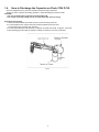
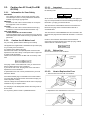
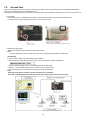
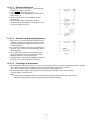
1.4.
How to Discharge the Capacitor on Flash CON P.C.B.
• This unit equipped with two pieces of capacitors as flash charging capacitors.
"Either one of the capacitor discharging operation" makes discharging for others as well.
CAUTION:
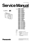
1. Be sure to discharge the capacitor on Flash CON P.C.B.
2. Be careful of the high voltage circuit on Flash CON P.C.B. when servicing.
[Discharging Procedure]
1. Refer to the disassemble procedure and remove the necessary parts/unit.
2. Put the insulation tube onto the lead part of Resistor (ERG5SJ102:1kΩ /5W).
(An equivalent type of resistor may be used.)
3. Put the resistor between both terminals of capacitor on Flash CON P.C.B. for approx. 5 seconds.
4. After discharging confirm that the capacitor voltage is lower than 10V using a voltmeter.
Fig. F1
4
2 Warning
2.1.
Prevention of Electrostatic Discharge (ESD) to Electrostatic Sensitive
(ES) Devices
Some semiconductor (solid state) devices can be damaged easily by static electricity. Such components commonly are called
Electrostatically Sensitive (ES) Devices.
The following techniques should be used to help reduce the incidence of component damage caused by electrostatic discharge
(ESD).
1. Immediately before handling any semiconductor component or semiconductor-equipped assembly, drain off any ESD on your
body by touching a known earth ground. Alternatively, obtain and wear a commercially available discharging ESD wrist strap,
which should be removed for potential shock reasons prior to applying power to the unit under test.
2. After removing an electrical assembly equipped with ES devices, place the assembly on a conductive surface such as
aluminum foil, to prevent electrostatic charge buildup or exposure of the assembly.
3. Use only a grounded-tip soldering iron to solder or unsolder ES devices.
4. Use only an antistatic solder removal device. Some solder removal devices not classified as
can
generate electrical charge sufficient to damage ES devices.
5. Do not use freon-propelled chemicals. These can generate electrical charges sufficient to damage ES devices.
6. Do not remove a replacement ES device from its protective package until immediately before you are ready to install it. (Most
replacement ES devices are packaged with leads electrically shorted together by conductive foam, aluminum foil or
comparable conductive material).
7. Immediately before removing the protective material from the leads of a replacement ES device, touch the protective material
to the chassis or circuit assembly into which the device will be installed.
CAUTION:
Be sure no power is applied to the chassis or circuit, and observe all other safety precautions.
8. Minimize bodily motions when handling unpackaged replacement ES devices. (Otherwise harmless motion such as the
brushing together of your clothes fabric or the lifting of your foot from a carpeted floor can generate static electricity (ESD)
sufficient to damage an ES device).
2.2.
How to Recycle the Lithium Ion Battery (U.S. Only)
5
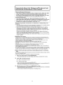
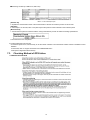
2.3.
2.3.1.
Caution for AC Cord (For EB/
GC/GH)
2.3.2.1.
Information for Your Safety
Blue
Brown
IMPORTANT
Your attention is drawn to the fact that recording of prerecorded tapes or discs or other published or broadcast
material may infringe copyright laws.
WARNING
To reduce the risk of fire or shock hazard, do not expose
this equipment to rain or moisture.
CAUTION
To reduce the risk of fire or shock hazard and annoying
interference, use the recommended accessories only.
FOR YOUR SAFETY
DO NOT REMOVE THE OUTER COVER
To prevent electric shock, do not remove the cover. No user
serviceable parts inside. Refer servicing to qualified service
personnel.
2.3.2.
Important
The wires in this mains lead are coloured in accordance with
the following code:
Neutral
Live
As the colours of the wires in the mains lead of this appliance
may not correspond with the coloured markings identifying the
terminals in your plug, proceed as follows:
The wire which is coloured BLUE must be connected to the
terminal in the plug which is marked with the letter N or
coloured BLACK.
The wire which is coloured BROWN must be connected to the
terminal in the plug which is marked with the letter L or coloured
RED.
Under no circumstances should either of these wires be
connected to the earth terminal of the three pin plug, marked
with the letter E or the Earth Symbol.
Caution for AC Mains Lead
For your safety, please read the following text carefully.
This appliance is supplied with a moulded three-pin mains plug
for your safety and convenience.
A 5-ampere fuse is fitted in this plug.
Should the fuse need to be replaced please ensure that the
replacement fuse has a rating of 5 amperes and it is approved
by ASTA or BSI to BS1362
Check for the ASRA mark or the BSI mark on the body of the
fuse.
2.3.2.2.
Before Use
remove the Connector Cover as follows.
If the plug contains a removable fuse cover you must ensure
that it is refitted when the fuse is replaced.
If you lose the fuse cover, the plug must not be used until a
replacement cover is obtained.
A replacement fuse cover can be purchased from your local
Panasonic Dealer.
2.3.2.3.
How to Replace the Fuse
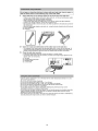
1. Remove the Fuse Cover with a screwdriver.
If the fitted moulded plug is unsuitable for the socket outlet in
your home then the fuse should be removed and the plug cut
off and disposed of safety.
There is a danger of severe electrical shock if the cut off plug is
inserted into any 13-ampere socket.
If a new plug is to be fitted please observe the wiring code as
shown below.
If in any doubt, please consult a qualified electrician.
2. Replace the fuse and attach the Fuse cover.
6
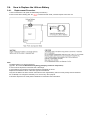
2.4.
2.4.1.
How to Replace the Lithium Battery
Replacement Procedure
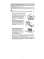
1. Remove the Main P.C.B. (Refer to Disassembly Procedures.)
2. Remove the Lithium battery (Ref. No.
at foil side of Main P.C.B.) and then replace it into new one.
Note:
The lithium battery is a critical component.
(Type No.: ML-421S/ZTK Manufactured by Energy Company, Panasonic Corporation)
It must never be subjected to excessive heat or discharge.
It must therefore only be fitted in equipment designed specifically for its use.
Replacement batteries must be of the same type and manufacture.
They must be fitted in the same manner and location as the original battery, with the correct polarity contacts observed.
Do not attempt to re-charge the old battery or re-use it for any other purpose.
It should be disposed of in waste products destined for burial rather than incineration.
7
Note:
Above caution is applicable for a battery pack which is for DMC-FT4 and DMC-TS4 series, as well.
Danger of explosion if battery is incorrectly replaced.
Replace only with the same or equivalent type recommended by the manufacturer.
Dispose of used batteries according to the manufacturer's instructions.
8
3 Service Navigation
3.1.
Introduction
This service manual contains technical information, which will allow service personnel's to understand and service this model.
Please place orders using the parts list and not the drawing reference numbers.
If the circuit is changed or modified, the information will be followed by service manual to be controlled with original service manual.
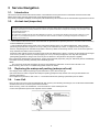
3.2.
Air-leak test (inspection)
Waterproof/Dustproof Performance
This camera's waterproof/dustproof rating complies with the "IPX8" and "IP6X" ratings. Provided the care and maintenance guidelines
described in this document are strictly followed, this camera can operate underwater, to a depth not exceeding 12 m (40 feet) for a time
not exceeding 60 minutes. (*1)
Anti-shock Performance
This camera also complies with "MIL-STD 810F Method 516.5-Shock". The camera has cleared a drop test from a height of 2 m (6.6
feet) onto 3 cm (0.10 feet) thick plywood. In most cases this camera should not sustain any damage if dropped from a height not
exceeding 2 m (6.6 feet). (*2)
This does not guarantee no destruction, no malfunction, or waterproofing in all conditions.
*1 This means that the camera can be used underwater for specified time in specified pressure in accordance with the handling
method established by Panasonic.
*2 "MIL-STD 810F Method 516.5-Shock" is the test method standard of the U.S. Defense Department, which specifies
performing drop tests from a height of 122 cm (4.0 feet), at 26 orientations (8 corners, 12 ridges, 6 faces) using 5 sets of
devices, and passing the 26 orientation drops within 5 devices. (If failure occurs during the test, a new set is used to pass the
drop orientation test within a total of 5 devices)
Panasonic’s test method is based on the above "MIL-STD 810F Method 516.5-Shock". However, the drop height was changed
from 122 cm (4.0 feet) to 200 cm (6.6 feet) dropping onto 3 cm (0.10 feet) thick plyboard. This drop test was passed.
(Disregarding appearance change such as loss of paint or distortion of the part where drop impact is applied.)
• Due to the above characteristics of the products, perform the air-leak test (inspection) using Air -leak tester (Part No.:RFKZ0528)
before/after servicing including assembly and/or assembly process.
Note:
The purpose of the air-leak test before servicing is that whether the malfunction occurred due to air-leak or not.
• When servicing, refer to the "7.Troubleshooting Guide" section for details.
3.3.
Replacing the waterproof packing (waterproof seal)
• The integrity of the waterproof packing may decrease about 1 year, with use and age.
(We recommend end users to replace the waterproof packing (waterproof seal) at least once each year described in the
operating instructions.)
• As for replacement procedure, refer to the 7.1.2. Periodical maintenance (Packing replacement) flow for details.
3.4.
Lens Unit
• Since the lens unit for this model is assembled with high accuracy manufacturing technologies, it is not allowed to disassemble/
assemble the lens unit, in terms of performance retention.
When servicing, it has to be handled the "Lens with CCD unit" as the smallest part size.
Confirm the replacement part list and exploded views for details.
9
3.5.
About IC9301 (COMPASS) [On the TOP FPC UNIT]
When IC9301 is defects and necessary to be replaced, replace with whole TOP FPC UNIT as a unit.
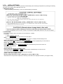
3.6.
General Description About Lead Free Solder (PbF)
The lead free solder has been used in the mounting process of all electrical components on the printed circuit boards used for this
equipment in considering the globally environmental conservation.
The normal solder is the alloy of tin (Sn) and lead (Pb). On the other hand, the lead free solder is the alloy mainly consists of tin
(Sn), silver (Ag) and Copper (Cu), and the melting point of the lead free solder is higher approx.30 °C (86 °F) more than that of the
normal solder.
Definition of P.C.B. Lead Free Solder being used
The letter of
is printed either foil side or components side on the P.C.B. using the lead free solder.
(See right figure)
Service caution for repair work using Lead Free Solder (PbF)
• The lead free solder has to be used when repairing the equipment for which the lead free solder is used.
•
•
•
•
(Definition: The letter of
is printed on the P.C.B. using the lead free solder.)
To put lead free solder, it should be well molten and mixed with the original lead free solder.
Remove the remaining lead free solder on the P.C.B. cleanly for soldering of the new IC.
Since the melting point of the lead free solder is higher than that of the normal lead solder, it takes the longer time to melt the
lead free solder.
• Use the soldering iron (more than 70W) equipped with the temperature control after setting the temperature at 350±30 degrees
C (662±86 °F).
Recommended Lead Free Solder (Service Parts Route.)
• The following 3 types of lead free solder are available through the service parts route.
RFKZ03D01KS-----------(0.3mm 100g Reel)
RFKZ06D01KS-----------(0.6mm 100g Reel)
RFKZ10D01KS-----------(1.0mm 100g Reel)
Note
* Ingredient: tin (Sn) 96.5%, silver (Ag) 3.0%, Copper (Cu) 0.5%, Cobalt (Co) / Germanium (Ge) 0.1 to 0.3%
10
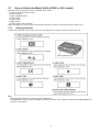
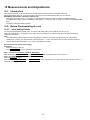
3.7.
How to Define the Model Suffix (NTSC or PAL model)
There are seven kinds of DMC-FT4/TS4, regardless of the colours.
• a) DMC-FT4 (Japan domestic model.)
• b) DMC-TS4P/PC
• c) DMC-FT4EB/EF/EG/EP
• d) DMC-FT4EE
• e) DMC-FT4GN
• f) DMC-TS4GD
• g) DMC-FT4GC, DMC-TS4GH/PU
What is the difference is that the "INITIAL SETTINGS" data which is stored in Flash ROM mounted on Main P.C.B.
3.7.1.
Defining methods
To define the model suffix to be serviced, refer to the nameplate which is putted on the bottom side of the Unit.
Note:
After replacing the Main P.C.B., be sure to achieve adjustment.
The Maintenance software (DIAS) is available at "software download" on the "Support Information from NWBG/VDBG-AVC"
web-site in "TSN system".
11
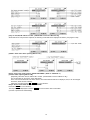
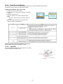
3.7.2.
INITIAL SETTINGS:
After replacing the Main P.C.B., be sure to perform the initial settings after achieving the adjustment by ordering the following
procedure in accordance with model suffix of the unit.
1. IMPORTANT NOTICE:
Before proceeding Initial settings, be sure to read the following CAUTIONS.
2. PROCEDURES:
• Precautions: Read the above "CAUTION 1" and "CAUTION 2", carefully
• Preparation:
1. Attach the Battery to the unit.
2. Set to P(Program AE) mode by operating the mode button.
Note:
If the picture mode is other than P(Program AE) mode, it does not display the initial settings menu.
• Step 1. The temporary cancellation of "INITIAL SETTINGS":
While keep pressing "UP of Cursor button" and MOTION PICTURE button simultaneously, turn the Power on.
• Step 2. The cancellation of "INITIAL SETTINGS":
Press the PLAYBACK button.
Press "UP of Cursor button" and MOTION PICTURE button simultaneously, then turn the Power off.
• Step 3. Turn the Power on:
Turn the Power on.
• Step 4. Display the "INITIAL SETTINGS" menu:
While keep pressing MENU/SET and "RIGHT of Cursor button" simultaneously, turn the Power off.
The "INITIAL SETTINGS" menu is displayed.
There are two kinds of "INITIAL SETTINGS" menu form as follows:
[CASE 1. After replacing Main P.C.B.]
[Except "EG, EF, EB and EP" models : (VEP56129C is used as a Main P.C.B.)]
When Main P.C.B. has just been replaced, the following model suffix list is displayed as follows. (Four pages in total)
12
[Only for "EG, EF, EB and EP" models : (VEP56129D is used as a Main P.C.B.)]
When Main P.C.B. has just been replaced, the following model suffix list is displayed as follows. (Two pages in total)
[CASE 2. Other than "After replacing Main P.C.B."]
• Step 5. Choose the model suffix in "INITIAL SETTINGS": (Refer to "CAUTION 1")
[Caution: After replacing Main P.C.B.]
(Especially, other than "EG, EF, EB and EP" models : (VEP56129D is used as a Main P.C.B.))
The model suffix can be chosen, JUST ONE TIME.
Once one of the model suffix have been chosen, the model suffix lists will not be displayed, thus, it can be changed.
Therefore, select the area carefully.
Select the area with pressing "UP / DOWN of Cursor buttons".
• Step 6. Set the model suffix at "INITIAL SETTINGS":
Press the "RIGHT of Cursor buttons".
The only set area is displayed. Press the "RIGHT of Cursor buttons" after confirmation.
(The unit is powered off automatically.)
13
• Step 7. CONFIRMATION:
Confirm the display of "PLEASE SET THE CLOCK" in concerned language when the unit is turned on again.
When the unit is connected to PC with USB cable, it is detected as removable media.
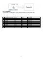
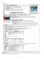
1) As for your reference, major default setting condition is as shown in the following table.
Default setting (After "INITIAL SETTINGS")
a)
b)
c)
d)
e)
f)
g)
h)
i)
j)
k)
l)
m)
MODEL
DMC-FT4(Japan domestic model)
DMC-FT4EB
DMC-FT4EE
DMC-FT4EF
DMC-FT4EG
DMC-FT4EP
DMC-FT4GC
DMC-FT4GN
DMC-TS4GH
DMC-TS4GD
DMC-TS4P
DMC-TS4PC
DMC-TS4PU
VIDEO OUTPUT
NTSC
PAL
PAL
PAL
PAL
PAL
PAL
PAL
PAL
NTSC
NTSC
NTSC
NTSC
LANGUAGE
Japanese
English
Russian
French
English
English
English
English
English
Korean
English
English
Spanish
14
DATE
Year/Month/Date
Date/Month/Year
Date/Month/Year
Date/Month/Year
Date/Month/Year
Date/Month/Year
Date/Month/Year
Date/Month/Year
Date/Month/Year
Year/Month/Date
Date/Month/Year
Date/Month/Year
Date/Month/Year
REMARKS
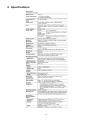
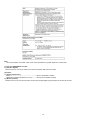
4 Specifications
15
Note:
*Above specification is for DMC-TS4P. Some of the specification may differ depends on model suffix.
[1] Only for "EB/EF/EG/EP" models:
1). [Interface Digital:]
• Data from the PC can not be written to the camera using the USB connection cable.
[2] Others:
1). [Analog video/audio:]
NTSC ----------------------------------------------------------(Only "P/PC/PU/GD" models)
NTSC/PAL Composite (Switched by menu) ----------(Except "P/PC/PU/GD" models)
2). [Motion pictures:]
• Maximum time to record motion pictures continuously with [GFS]/[FSH] in [AVCHD] is 29 minutes 59 seconds.
16
17
18
19
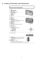
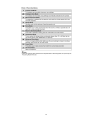
5 Location of Controls and Components
20
21
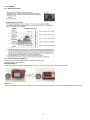
6 Service Mode
6.1.
Error Code Memory Function
1. General description
This unit is equipped with history of error code memory function, and can be memorized 16 error codes in sequence from the
latest. When the error is occurred more than 16, the oldest error is overwritten in sequence.
The error code is not memorized when the power supply is shut down forcibly (i.e.,when the unit is powered on by the battery,
the battery is pulled out) The error code is memorized to FLASH ROM when the unit has just before powered off.
2. How to display
The error code can be displayed by ordering the following procedure:
• Preparation:
1. Attach the Battery to the unit.
Note:
*Since this unit has built-in memory, it can be performed without inserting SD memory card.
*Select the mode other than "3D" mode (such as Program AE / iA / Sports / Snow / SCN)
to display the error code.
• Step 1. The temporary cancellation of "INITIAL SETTINGS":
While keep pressing "UP of Cursor button" and MOTION PICTURE button simultaneously, turn the Power on.
• Step 2. Execute the error code display mode:
Press the "LEFT of Cursor button", MENU/SET button and MOTION PICTURE button simultaneously.
The display is changed as shown below when the above buttons are pressed simultaneously.
Normal display → Error code display → CAMERA INFO → Normal display → .....
22
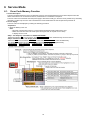
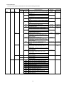
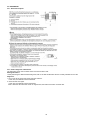
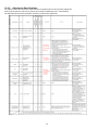
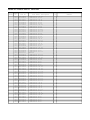
3. Error Code List
The error code consists of 8 bits data and it shows the following information.
Attribute Main item Sub item
LENS
Lens drive OIS
Error code
High 4bits Low 4 bits
18*0
1000
2000
3000
4000
5000
6000
7000
Zoom
0?10
0?20
0?60
Focus
0?01
0?02
Lens
Adj.History OIS
18*1
0000
18*2
0000
19*0
2000
3000
4000
5000
6000
7000
8000
9000
A000
B000
C000
D000
E000
Contents (Upper)
Check point (Lower)
Error Indication
Detecting
Part/Circuit
device
OIS X
LENSu NG
PSD (X) error. Hall element (X axis) position detect
error in OIS unit.
OIS Unit
PSD (Y) error. Hall element (Y axis) position detect
OIS Y
error in OIS unit.
OIS Unit
GYRO (X) error. Gyro (IC6301) detect error on Top
GYRO X
GYRO NG
P.C.B.
IC6301 (Gyro element) or IC6001 (VENUS ENGINE)
GYRO (Y) error. Gyro (IC6302) detect error on Top
GYRO Y
P.C.B.
IC6302 (Gyro element) or IC6001 (VENUS ENGINE)
MREF error (Reference voltage error).
OIS REF
LENSSd/DSP
NG
IC9101 (LENS DRIVE) or IC6001 (VENUS ENGINE)
Drive voltage (X) error.
OISX REF
LENSu/LENS
FPC
LENS Unit, LENS flex breaks, IC6001(VENUS
ENGINE) AD value error, etc.
Drive voltage (Y) error.
OISY REF
LENS Unit, LENS flex breaks, IC6001(VENUS
ENGINE) AD value error, etc.
Collapsible barrel Low detect error
ZOOM L
ZOOMm/
(Collapsible barrel encoder always detects Low.)
LENSu
Mechanical lock, FP9002-(40) signal line or IC6001
(VENUS ENGINE)
Collapsible barrel High detect error
ZOOM H
(Collapsible barrel encoder always detects High.)
Mechanical lock, FP9002-(40) signal line or IC6001
(VENUS ENGINE)
The zoom position jump is detected due to the
(No indication) (No indication)
impact (i.e. drop.) to the camera occurs.
Lens unit
FOCUS L
LENS FPC/
HP High detect error
DSP
(Focus encoder always detects High, and not
becomes Low)
Mechanical lock, FP9002-(40) signal line or IC6001
(VENUS ENGINE)
FOCUS H
HP Low detect error
(Focus encoder always detects Low, and not
becomes High)
Mechanical lock, FP9002-(40) signal line or IC6001
(VENUS ENGINE)
Power ON time out error.
LENS DRV
LENSu
Lens drive system
Power OFF time out error.
Lens drive system
OIS adj. Yaw direction amplitude error (small)
OIS ADJ
OIS ADJ
OIS adj. Pitch direction amplitude error (small)
OIS adj. Yaw direction amplitude error (large)
OIS adj. Pitch direction amplitude error (large)
OIS adj. MREF error
OIS adj. time out error
OIS adj. Yaw direction off set error
OIS adj. Pitch direction off set error
OIS adj. Yaw direction gain error
OIS adj. Pitch direction gain error
OIS adj. Yaw direction position sensor error
OIS adj. Pitch direction position sensor error
OIS adj. other error
23
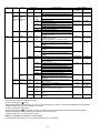
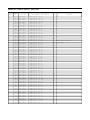
Attribute Main item Sub item
HARD
VENUS A/
D
FLASH
ROM
(EEPROM
Area)
Error code
High 4bits Low 4 bits
Flash
28*0
0000
FLASH
ROM
(EEPROM
Area)
2B*0
0001
0003
0004
0002
0005
SOFT
SYSTEM
RTC
2C*0
CPU
Reset
30*0
Card
Card
31*0
0008
0009
0001
0001
|
0007
0001
0002
0004
CPU,
Stop
ASIC hard
39*0
38*0
0005
0001
0002
0100
0200
3A*0
0300
0008
Operation Power on
3B*0
0000
Zoom
3C*0
0000
35*0
35*1
0000
|
FFFF
0000
35*2
0000
Memory
area
Zoom
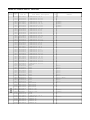
Contents (Upper)
Check point (Lower)
Flash charging error.
IC6001-(AC16) signal line or Flash charging circuit
EEPROM read error
Error Indication
Detecting
Part/Circuit
device
STRB CHG
Flash CON
P.C.B./FPC
FROM RE
FROM
IC6002 (FLASH ROM)
EEPROM write error
FROM WR
FROM
IC6002 (FLASH ROM)
Firmware version up error
(No indication) (No indication)
Replace the firmware file in the SD memory card.
SDRAM error
SDRAM Mounting defective
SYSTEM IC initialize failure error
SYS INIT
Main P.C.B.
Communication between IC6001 (VENUS ENGINE)
and IC9101 (SYSTEM)
NMI RST
Main P.C.B.
NMI reset
Non Mask-able Interrupt
(30000001-30000007 are caused by factors)
Card logic error
SD CARD
SD CARD/
DSP
SD memory card data line or IC6001 (VENUS
ENGINE)
Card physical error
SD memory card data line or IC6001 (VENUS
ENGINE)
Write error
SD WRITE
SD memory card data line or IC6001 (VENUS
ENGINE)
Format error
INMEMORY
FROM
Camera task finish process time out.
LENS COM
LENSu/DSP
Communication between Lens system and IC6001
(VENUS ENGINE)
Camera task invalid code error.
DSP
DSP
IC6001 (VENUS ENGINE)
File time out error in recording motion image
IC6001 (VENUS ENGINE)
File data cue send error in recording motion image
IC6001 (VENUS ENGINE)
Single or burst recording brake time out.
USB work area partitioning failure
(No indication) (No indication)
USB dynamic memory securing failure when
connecting
FLASHROM processing early period of camera
INIT
(No indication)
during movement.
Imperfect zoom lens processing
ZOOM
ZOOMm/
LENSu
Zoom lens
Software error
DSP
DSP
(0-7bit : command, 8-15bit : status)
Though record preprocessing is necessary, it is not
called.
Though record preprocessing is necessary, it is not
completed.
(No indication) (No indication)
1) About "*" indication:
The third digit from the left is different as follows.
In case of 0 (example: 18 0 01000)
When the third digit from the left shows "0", this error occurred under the condition of INITIAL SETTINGS has been completed.
It means that this error is occurred basically at user side.
In case of 8 (example: 18 8 01000)
When the third digit from the left shows "8", this error occurred under the condition of INITIAL SETTINGS has been released.
(Example; Factory assembling-line before unit shipment, Service mode etc.)
It means that this error is occurred at service side.
2) About "?" indication: ("18*0 0?01" to "18*0 0?50"):
The third digit from the right shows one of the hexadecimal ("0" to "F") character.
24
4. How to returned to Normal Display:
Turn the power off and on, to exit from Error code display mode.
Note:
The error code can not be initialized.
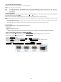
6.2.
ICS (Indication of additional Camera Settings when picture was taken)
function
1. General description
This unit is equipped with ICS (ICS: Indication of additional Camera Settings when picture was taken) function by playing back the
concerned picture on the LCD display.
(This function is achieved by utilizing "maker note" data stored in Exif data area of recorded picture file.)
To proceed failure diagnosis, use this ICS function together with "displaying the recorded picture with picture information" function.
Note:
*.The ICS function operates with a picture which is only taken with the same model. (It may not be displayed when the picture
was taken with other model.)
*.Since Exif data is not available after the picture is edited by PC, the ICS function may not be activated.
2. How to display
The ICS data is displayed by ordering the following procedure:
• Preparation:
1.Attach the Battery to the unit.
Note:
*Select the mode other than "3D "mode (such as Program AE / iA / Sports / Snow / SCN) to display the ICS data.
• Step 1. The temporary cancellation of "INITIAL SETTINGS":
While keep pressing "UP of Cursor button" and MOTION PICTURE button simultaneously, turn the Power on.
• Step 2. Execute the ICS display mode:
Press the PLAYBACK button.
Select the concerned picture by pressing the "LEFT and RIGHT of Cursor button".
Press the "LEFT of Cursor button", MENU/SET button and MOTION PICTURE button simultaneously.
Press the DISPLAY button, 3 times.
The display condition is changed as shown below when the DISPLAY button is pressed.
Code display → Code + Picture display (1) → Code + Picture display (2) → ICS display → .....
25
3. How to read
4. How to exit
Simply, turn the power off. (Since ICS function is executed under the condition of temporary cancellation of "INITIAL SETTINGS",it
wake up with normal condition when turn off the power.)
26
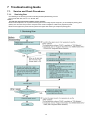
7 Troubleshooting Guide
7.1.
7.1.1.
Service and Check Procedures
Servicing flow
• The following is the servicing procedure including assembly/disassembly process.
• As for the air-leak test, refer to "7.2. Air-leak Test".
< Note >
Air-leak test (inspection) before taking service measure:
• When the first inspection, do not perform cleaning (removal of foreign objects caught etc.) of the waterproof packing parts
(battery door and Jack door) from the viewpoint of the cause investigation at NG of test (inspection) result.
• When the test (inspection) result was NG, perform test again after cleaning of waterproof packing parts.
27
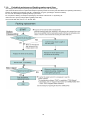
7.1.2.
Periodical maintenance (Packing replacement) flow
• The integrity of the waterproof packings may decrease about 1 year, with use and age.
(We recommend end-users to replace the waterproof packing at least once each year described in the operating instructions.)
• Please use waterproof packing kit (Part No.: VUMG1978). (5 types, 8 packings in total are included)
• Do not touch the waterproof packings directly by the hand.
• Do not perform cleaning of waterproof packings by the solvent of alcohol etc. or by blowing air.
• Take care not to put any foreign objects (garbage and dust).
• As for the air-leak test, refer to "7.2. Air-leak Test".
28
Replacing the waterproof packing
• The location of waterproof packing are shown at right. (5 types, 8 packings in total)
• Waterproof packings are supplied as Waterproof packing kit (Part No.: VUMG1978).
< Note for replacement >
• Do not touch the waterproof packings directly by the hand.
• Do not perform cleaning of waterproof packings by the solvent of alcohol etc. or by blowing air.
• Take care not to put any foreign objects (garbage and dust).
• Use the silicon chips (Part No.: RFKZ0478) when replacing the Case O-ring.
29
7.2.
Air-leak Test
Due to the waterproof performance retention, perform the air-leak test using Air-leak tester (Part No.:RFKZ0528) before/after
servicing when disassembling and assembling the unit.
*The Air-leak test before servicing is necessary to be performed to check whether the malfunction occurred due to air-leak or not.
1. Preparation:
1) By referring the "9.3. Disassembly procedures", remove the side ornament (R) and front aluminum case.
2) Confirm that no foreign objects at the side door, and it is firmly closed.
2. Air-leak Test (Inspection):
*Perform the air-leak test by referring the following procedure.
Note:
As for the detail instruction of air-leak tester, refer to the operating guide (attached to the product).
[Preparation]
1. Put the camera with the top case facing upward condition.
2. Set the following measurement pressure value on the air-leak tester. (Part No.:RFKZ0528).
*About the Setting methods, refer to the operating guide for air-leak tester.
3. Attach "L" size of absorption pad to the tip of the hose of the air-leak tester.
4. Put the absorption pad of air-leak tester vertically on the Microphone part.
Note:
• Keep firmly hold above condition until the measurement is completed.
Once pad is tilted/misaligned from the test hole during testing process, start it from this step.
30
QMeasuring condition (For DMC-FT4, DMC-TS4)
*Attach "L" size of absorption pad.
[Exhaust Air]
5. Operate the measurement switch of the air-leak tester to exhaust air inside the product for 90 seconds.
[Stand-by]
6. After a laps of 15 seconds, take a note (Record) that the pressure value indicated on the indication panel.
[Measurement]
7. Confirm that the pressure value fluctuations during measurement process are within the testing specifications
The air-leak test is now completed.
3. Packing replacement record input:
• To enter the repair record, it is necessary to use the "DIAS" software. The maintenance software "DIAS" is available at "TSN
Website".
To download, click on "Support Information from NWBG/VDBG-AVC".
*DIAS (DSC Integrated Assist Software)
7.3.
Checking Method of GPS failure
1. GENERAL DESCRIPTION
31
2. Checking flowchart of GPS failure.
The checking flowchart of GPS failure is as follows:
Note:
*Perform the GPS communication test, even if the repair being carried out is not related with GPS function.
*The GPS function in this unit is performed communication between GPS module (Mic GPS FPC Unit) and VENUS
(IC6001: on the Main P.C.B.).
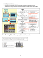
7.4.
Checking Method of compass, altimeter, & barometer
1. GENERAL DESCRIPTION
32
2. ABOUT EACH SENSOR
2.1. COMPASS
2.1.1. General description
2.1.2. Failure diagnosis of Compass.
The Compass sensor unit is IC9301 which is located on TOP FPC unit.
Since the IC9301 does not supply as a spare parts, replace as a TOP FPC unit if necessary.
Settings/Condition:
1. Release the initial settings to be forcefully turned off the declination adjustment:
2. Turn on the GPS setting.
3. Press the Display button to display the compass, altimeter, & barometer.
4. Select [Calibrate compass] on the [GPS/Sensor] menu, and then press [MENU/SET].
5. Securely hold the unit vertically, and adjust by turning it in a figure 8 a few times rolling your wrist.
The "Calibration successful" is displayed when the adjustment is successful.
Diagnosis:
1. When both of the red arrow of compass unit and camera unit's one point same direction, the built-in compass unit works fine.
33
2.2. ALTIMETER
2.2.1. General description
2.2.2. Failure diagnosis of Altimeter.
The Altimeter sensor unit is IC9202 which is located on Main PCB.
(It detects direction of gravitation.)
Settings/Condition:
1.After performing the compass failure diagnosis, face down (the LCD side up) the camera unit, gradually.
Diagnosis:
1.When the compass in the camera unit points same direction before and after above condition, the built-in altimeter unit works fine.
34
2.3. BAROMETER
2.3.1. General description
2.3.2. Failure diagnosis of Barometer.
The barometer sensor unit is IC9201 which is located on Main P.C.B.
Settings/Condition:
1.After performing the altimeter failure diagnosis, take a note that the altimeter which is currently indicated on the LCD.
Diagnosis:
1. Do not turn off the power, but simply open the side door.
In this case, the altimeter value is increased.
2. Close the side door again.
In this case, the altimeter value is decreased.
After a while the value becomes closer to original value, the built-in barometer unit works fine.
35
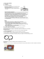
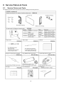
8 Service Fixture & Tools
8.1.
Service Fixture and Tools
The following Service Fixture and tools are used for checking and servicing this unit.
36
8.2.
When Replacing the Main P.C.B.
After replacing the Main P.C.B., be sure to achieve adjustment.
The Maintenance software (DIAS) is available at "software download" on the "Support Information from NWBG/VDBG-AVC" website in "TSN system".
8.3.
Service Position
This Service Position is used for checking and replacing parts. Use the following Extension cables for servicing.
Table S1 Extension Cable List
No.
1
8.3.1.
Parts No.
RFKZ0549
Connection
FP9006 (Main P.C.B.) - FP8001 (Flash CON P.C.B.)
Form
18PIN 0.5 FFC
Extension Cable Connections
CAUTION-1. (When servicing Flash CON P.C.B.)
1. Be sure to discharge the capacitor on Flash CON P.C.B.
Refer to "HOW TO DISCHARGE THE CAPACITOR ON FLASH CON P.C.B.".
The capacitor voltage is not lowered soon even if the AC Cord is unplugged or the battery is removed.
2. Be careful of the high voltage circuit on Flash CON P.C.B.
3. DO NOT allow other parts to touch the high voltage circuit on Flash CON P.C.B.
37
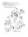
9 Disassembly and Assembly Instructions
9.1.
Disassembly Flow Chart
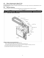
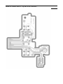
9.2.
P.C.B. Location
38
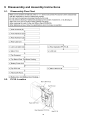
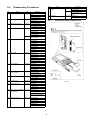
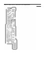
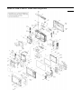
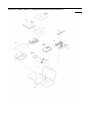
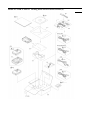
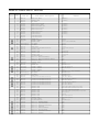
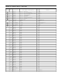
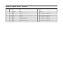
9.3.
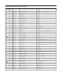
Disassembly Procedures
No.
Item
14 Rear Operation FPC
P.C.B.
No.
Item
1 Side Ornament (R)
2
3
4
5
6
7
8
9
10
11
12
13
Fig.
Removal
Fig. D1 SD Card
Battery
2 Screws (A)
Side Ornament (R)
Front Aluminum Case
Fig. D2 2 Hex. Screws (B)
2 Screws (C)
Front Aluminum Case
Rear Aluminum Case
Fig. D3 2 Hex. Screws (D)
1 Screw (E)
Rear Aluminum Case
Rear Case Unit
Fig. D4 6 Screws (F)
FP9004 (Flex)
FP9005 (Flex)
FP9007 (Flex)
Rear Case Unit
Fig. D5 Note: When attaching the
Rear case Unit
Lens Unit (with CCD)
Fig. D6 1 Screw (G)
2 Screws (H)
1 Screw (I)
1 Screw (J)
FP9002 (Flex)
FP9003 (Flex)
1 Screw O-ring
Lens Plate
Lens Unit (with CCD)
Main P.C.B.
Fig. D7 2 Screws (K)
FP9001 (Flex)
FP9006 (Flex)
FP9008 (Flex)
DPR Sheet (Large)
DPR Sheet (Small)
Main P.C.B.
Top Ornament
Fig. D8 1 Screw (L)
1 Locking tab (A)
1 Locking tab (B)
Top Earth Plate
Top Ornament
Top Button Plate/Top
Fig. D9 2 Screws (M)
Button Packing
Top Button Plate
Top Button Packing
Battery Frame Unit
Fig. D10 1 Screw (N)
1 Screw O-ring
Battery Frame Unit
Top FPC Unit
Fig. D11 2 Screws (O)
Top FPC Unit
Flash CON P.C.B.
Fig. D12 1 Screw (P)
2 Locking tabs
FL Earth Plate
Flash CON P.C.B.
Battery Door Unit (Battery Fig. D13 2 Screws (Q)
Door Packing )
Battery shaft
Battery Door Spring
Battery Door Unit (Battery
Door Packing)
MIC G FPC P.C.B.
Fig. D14 2 Screws (R)
1 Screw (S)
2 Screw O-rings
GPS FPC Plate
GPS Module
MIC G FPC P.C.B.
15 LCD Unit
9.3.1.
Fig.
Removal
Fig. D15 10 Screws (T)
Rear FPC Plate
Fig. D16 Rear Button Unit
Rear Operation FPC
P.C.B.
Fig. D17 4 Screws (U)
LCD Unit
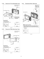
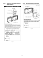
Removal of Side Ornament (R)
Fig. D1
39
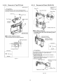
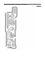
9.3.2.
Removal of Front Aluminum Case
9.3.4.
Removal of Rear Case Unit
Fig. D2
9.3.3.
Removal of Rear Aluminum Case
Fig. D4
Fig. D3
40
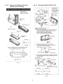
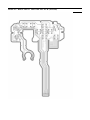
9.3.5.
Removal of Lens Unit (with CCD)
Note: (When Disassembling/Assembling)
1. When dust stuck, use air-Blower to blow off the dust.
2. Do not touch the surface of lens by your hand.
3. Use Lens Cleaning KIT; VFK1900BK (Only supplied as
10 set/Box) is available as Service Aid.
Fig. D5
Fig. D6
41
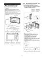
9.3.6.
Removal of Main P.C.B.
9.3.7.
Removal of Top Ornament
Fig. D8
Fig. D7
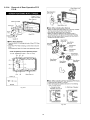
42
9.3.8.
Removal of Top Button Plate/Top
Button Packing
9.3.9.
Removal of Battery Frame Unit
Fig. D10
Fig. D9
43
9.3.10. Removal of Top FPC Unit
9.3.11.
Removal of Flash CON P.C.B.
Fig. D11
Fig. D12
44
9.3.12. Removal of Battery Door Unit
(Battery Door Packing)
9.3.13. Removal of MIC G FPC P.C.B.
Fig. D13
Fig. D14
45
9.3.14. Removal of Rear Operation FPC
P.C.B.
Fig. D15
Fig. D16
46
9.3.15. Removal of LCD Unit
Fig. D17
47
10 Measurements and Adjustments
10.1. Introduction
When servicing this unit, make sure to perform the adjustments necessary based on the part(s) replaced.
Before disassembling the unit, it is recommended to back up the camera data stored in flash-rom as a data file.
IMPORTANT NOTICE (After replacing the Main P.C.B.)
After replacing the Main P.C.B., it is necessary to use the "DIAS" software to allow the release of adjustment flag(s).
The Adjustment software "DIAS" is available at "TSN Website". To download, click on "Support Information from NWBG/VDBGAVC".
*DIAS (DSC Integrated Assist Software)
10.2. Before Disassembling the unit
10.2.1. Initial Setting Release
The cameras specification are initially set in accordance with model suffix (such as EB, EG, GC, and so on.).
Unless the initial setting is not released, an automatic alignment software in the camera is not able to be executed when the
alignment is carried out.
Note:
The initial setting should be again done after completing the alignment. Otherwise, the camera may not work properly.
Therefore as a warning, the camera display a warning symbol " ! " on the LCD monitor every time the camera is turned off.
Refer to the procedure described in "3.7.2. INITIAL SETTINGS" for details.
[How to Release the camera initial setting]
Preparation:
Attach the Battery to the unit.
Set to P(Program AE) mode by operating the mode button.
Step 1. Temporary cancellation of "INITIAL SETTINGS":
While pressing the UP of Cursor button and MOTION PICTURE button simultaneously, turn the Power on.
Step 2. Cancellation of "INITIAL SETTINGS":
Press the PLAYBACK switch.
While pressing UP of Cursor button and MOTION PICTURE button simultaneously, turn the Power off. (The warning symbol " ! " is
displayed on the LCD monitor.)
48
10.2.2. Flash-Rom Data Backup
When trouble occurs, it is recommended to backup the Flash-rom data before disassembling the unit.
There are two kinds of Flash-rom data backup methods:
[ROM_BACKUP (Method of Non-PC backup)]
1. Insert the SD-card into the camera.
2. Set the camera to "Temporary cancellation of the initial
settings".
3. Select the "SETUP" menu.
From the "SETUP" menu, select "ROM BACKUP".
Note:
This item is not listed on the customer's "SET UP"
menu.
4. When this "ROM_BACKUP" item is selected, the
following submenus are displayed.
[DSC Integrated Assist Software (Method of Using PC)]
Same as TATSUJIN software for previous models.
10.2.3. Light Box
If using VFK1164TDVLB Light Box, remove the lens connection
ring by loosing three hexagon screws.
49
10.3. Details of Electrical Adjustment
10.3.1. How to execute the Electrical Adjustment
It is not necessary to connect the camera to a PC to perform adjustments.
"Flag reset operation" and "Initial setting operation" are required when carrying out the alignment, follow the procedure below.
10.3.1.1. Startup Electrical Adjustment mode
1. Release the initial settings.
2. Insert a recordable SD card.
(Without a SD card, the automatic adjustment can not
executed.)
3. Procedure to set the camera into adjustment mode:
a. Set to P(Program AE) mode by operating the mode
button.
b. Turn the Power off.
c. Turn the Power on pressing MOTION PICTURE and
MENU/SET simultaneously.
LCD monitor displays "SERVICE MODE".
(Refer to Fig.F3-1)
Fig. 3-1
10.3.1.2. Status Adjustment Flag Setting
Reset (Not yet adjusted) the status flag condition.
1. After pressing the DISPLAY button, the LCD monitor
displays the Flag status screen (Refer to Fig.3-2.)
2. Select item by pressing the cross keys. (Gray cursor is
moved accordingly.)
3. Press the DELETE button.
Note:
The selected item's flag has been changed from
"F (green)" to "0 (yellow)".
*(Refer to Fig. 3-3)
*Flag conditions:
F (green)
means that the alignment has been completed and the
status flag condition is set. In this case, the flag condition
should be reset, if you try to carry out the automatic
alignment.
0 (yellow)
means that the alignment has been not "completed" and
the status flag condition is "reset". In this case, automatic
alignment is available.
Fig. 3-2
Fig. 3-3
< Example: OIS flag is reset. >
• In case of setting the status flag into set condition again without completion of the alignment, the status flag should be SET by
using PC, or UNDO by using ROM BACKUP function.
50
10.3.1.3. Execute Adjustment
1. Perform step "10.3.1.1." to "10.3.1.2.", to reset the OIS
flag status "F" (Set) to "0" (Reset).
2. Press DISPLAY button after Flag reset.
OIS Adjustment screen is displayed on the LCD panel.
(Refer to Fig.3-4)
3. Press the shutter button. The adjustment will start
automatically.
4. When the adjustment is completed successfully,
adjustment report menu appears with Green OK on the
LCD monitor. (Refer to Fig.3-5)
Fig. 3-4
Fig. 3-5
10.3.1.4. Attention point during Adjustment
1. Step "10.3.1.3." procedure shows OIS adjustment as an
example. To perform the adjustment, refer to the "10.3.2.
Adjustment Specifications" table which shows key point
for each adjustment.
2. Do not move the light box, the camera or the chart while
adjusting. If one of these is moved accidentally, start the
adjustment again.
3. Do not press any buttons/keys until the default menu
(Fig.3-6) is displayed on the LCD monitor. Otherwise,
adjustment data may not be stored properly.
4. If the adjustment is interrupted accidentally, the alignment
data may not be properly saved in the Flash-rom.
Fig. 3-6
10.3.1.5. Finalizing the Adjustment
1. Several adjustment flags can be reset ("F" into "0") at the same time. In this case, when the adjustment has been completed,
the screen will change showing the adjustment for the next item until all reset items are completed.
Also, when the shutter button is pressed, the screen jump to the next adjustment item.
2. To cancel the adjustment mode while in the process of performing the adjustment, follow this procedures.
(1) Press "Right of cross key" button.
Note:
*.If adjustment is cancelled with above procedure, adjustment is not completed. Make sure to adjust it later.
*.Adjustment software "DIAS" is able to control the status of the adjustment flags.
51
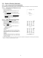
10.3.2. Adjustment Specifications
The following matrix table shows the relation between the replaced part and the Necessary Adjustment.
When a part is replaced, make sure to perform the necessary adjustment(s) in the order indicated.
The table below shows all the information necessary to perform each adjustment.
52
Q IMPORTANT NOTICE (After replacing the Main P.C.B.)
After replacing the MAIN P.C.B., make sure to perform the
"INITIAL SETTINGS" first, then release the "INITIAL
SETTINGS" in order to proceed the electrical adjustment.
Note:
1. If electrical adjustment or data re-writing is executed
before "INITIAL SETTINGS", suffix code list is never
displayed, and it cannot be chosen suitable suffix code.
2. Never remove the battery during initial setting in process.
10.4. After Adjustment
10.4.1. Initial Setting
Since the initial setting has been released to execute the built-in adjustment software, it should be set up again before shipping the
camera to the customer.
Refer to the procedure described in "3.8.2. INITIAL SETTINGS" for details.
[IMPORTANT]
1. The initial setting should be done again after completing the alignment. Otherwise, the camera will not work properly.
Therefore as a warning, the camera display a warning symbol " ! " on the LCD monitor every time the camera is turned off.
2. Confirm that status of all adjustment flag show "F". Even if one of the adjustment flag shows "0", initial setting programmed is
never executed.
3. Adjustment software "DIAS" is able to control the status of the adjustment flags.
The Adjustment software "DIAS" is available at "TSN Website", therefore, access to "TSN Website" at "Support Information
from NWBG/VDBG-AVC".
53
11 Maintenance
11.1. Cleaning Lens and LCD Panel
Do not touch the surface of lens and LCD Panel with your hand.
When cleaning the lens, use air-Blower to blow off the dust.
When cleaning the LCD Panel, dampen the lens cleaning paper with lens cleaner, and the gently wipe the their surface.
Note:
The Lens Cleaning KIT; VFK1900BK (Only supplied as 10 set/Box) is available as Service Aid.
54
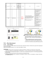
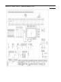
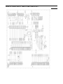
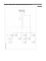
12 Block Diagram
12.1. Overall Block Diagram
IC6002
(28mm - 128mm)
CCD
1/2.33" 12.5 MEGA PIX
ZOOM
IRIS
SHUTTER
OIS UNIT
IC3001
PREPROCESS
FLASH ROM
/512Mbit
CDS,AGC
A/D,TG,
CCD DRIVER
SDRAM/512Mbit
FOCUS
SD
CARD
JK2004
HDMI
IC9601
HDMI CONTROLER
IC9101
MOTOR DRIVE
OIS DRIVE &
PRE PROCESS
IC9101
MICROPHONE
MICROPHONE ANT
AUDIO INTERFACE
IC7103
GYRO
SENSOR X/Y
IC6001
VENUS ENGINE
STROBE
SPEAKER
MONAURAL 16bit CODEC
MONAURAL MIC AMP
MONAURAL LINE AMP
SPEAKER AMP
SYSTEM DRIVER
(VIDEO 6dB AMP)
VIDEO/AUDIO
USB
JK2001
AV/USB
TERMINAL
CAMERA PROCESS
J-PEG COMP / EXPANDS
MEDIA I/F
USB I/F
MAIN MICRO PROCESSOR
OIS CONTROL
LENS DRIVE
LCD DRIVE
IC8001
FLASH CONTROL
REAR OPERATION UNIT
IC9202
(ACCELERATION SENSOR)
IC9201
IC9101
SYSTEM
DRIVER
(PRESSURE SENSOR)
GPS MODULE
COLOUR LCD
PANEL
2.7" PANEL
230K PIX
TOP OPERATION UNIT
(Type of LCD Driver Inclusion)
IC1001
POWER
(SWITCHING REGULATOR)
BATTERY
DMC-FT4/TS4 OVERALL BLOCK DIAGRAM
55
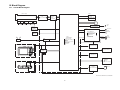
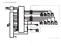
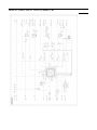
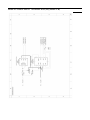
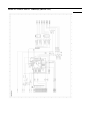
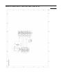
12.2. System Control Block Diagram
IC6001
(VENUS ENGINE)
IC9001
REAR OPERATION FPC P.C.B.
(IIC CLK/DATA BUFFER)
TO LCD
FP9007
2
2 SCK
FP9007
3
5 CS
FP9007
1
7 DI
LCD CS 3
B4 LCD CS
SCK 6
SO 1
KEY UP AC15
FP9004 FT6401
10
KEY DOWN AC5
FP9004 FT6401
14
KEY RIGHT AO15
FP9004 FT6401
11
KEY LEFT V3
FP9004 FT6401
13
IC9101
(SYSTEM IC)
SDDETOUT 51
Y6 SDCD_SYS
POWERSWONH 54
AA23 POWER_SW_ON
RESETOUT 85
RIGHT
DOWN
UP
S6403
S6407
S6405
1
2
1
2
1
2
1
2
3
4
3
4
3
4
3
4
AD7 SYS_RESET
PWMIN 81
T3 STB_PWM
AA20 SHUT_HALF
SHUTER HALF 57
POWERONH 84
AB1 POWER_ON_H
ED1 120
AC6 SHUT IN 1
ED2 44
AB7 SHUT IN 2
EC1 1
AA10 PWM ZOOM A
KEY DELETE Y1
FP9004 FT6401
15
KEY DISPLAY U3
FP9004 FT6401
16
KEY MENU W4
FP9004 FT6401
12
FP9004 FT6401
8
FP9004 FT6401
9
MODE AA16
EC2 2
AC8 PWM ZOOM B
RL9101
28 OSCIN
SCCS 67
X9101
LEFT
S6409
AC3 SYSCON CS
TELE
FP9004 FT6401
7
TELE WIDE AA15
MODE
PLAY
MENU
DISPLAY
S6402
S6408
S6406
S6404
DELETE
S6410
1
2
1
2
1
2
1
2
1
2
3
4
3
4
3
4
3
4
3
4
WIDE
RL9104
26 OSCOUT
C2 SYSCON SI
SO 74
RL9103
D9119
F5 SYSCON SO
SCSI 71
RL9102
SCSCLK 70
E3 SYSCON SCK
TOP FPC UNIT
POWER
SDO 7
CSB 5
S6303
FP9001 FT6301
19
C5 S ACCEL CS
SCK 6
1
2
3
4
T2 ACCEL INTERRUPT
INT 4
SDI 8
PLAY A3
IC9202
(ACCELERATION SENSOR)
POWERSWONL 87
BATT 27
B6402
ML-421S/ZT
DMC-FT4/TS4 SYSTEM CONTROL BLOCK DIAGRAM
56
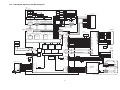
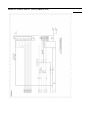
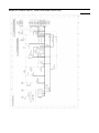
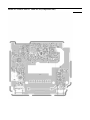
12.3. Video/Audio Signal Process Block Diagram
IC6002
(FLASH ROM/SDRAM)
BANK0
BANK2
BANK1
BANK3
X CDEODERS
512Mbit(2Mx32bitx4pcs)
COLUMN
DECODER
Y DECODERS
A9-A25
X-BUFFERS
LATCHES
& DECODERS
512M + 16M Bits
NAND FLASH
ARRAY
A0-A7
Y-BUFFERS
LATCHES
& DECODERS
(512 + 16)BYTES x 131,072
PAGE REGISTER & S/A
LCD UNIT
Y-GATING
ROW
DECODER
(Type of LCD Drive inclusion)
COMMAND
CLK18LCD
I/O BUFFERS & LATCHES
COMMAND
REGISTER
LCDHD
I/O BUFFER & GATE
ADDRESS BUFFER & REGISTER
TIMING & MODE REGISTER
CONTROL LOGIC
& HIGH VOLTAGE
GENERATOR
GLOBAL
BUFFERS
LCDVD
OUTPUT
DRIVER
LCDOUT0
LCDOUT1
DATA
12, 22-24, 31, 32, 41,
42, 83, 84, 91-93
73 82 58 78 56 48 37 72 52 62 81 33 77 55 67 35
7 3 6
4
14
13
I/O7N
I/O0N
RBM
WPN
ALEN
WEN
REN
CEN
CLEN
LCDOUT2
BA0D
BA1D
CLKD
DQM0D
DQM1D
DQM2D
DQM3D
CSD
RASD
CASD
WED
CKED
DQS0
DQS1
DQS2
DQS3
17, 18, 25-28, 34, 36,
38, 44-47, 53, 54, 57,
63-66, 74-76, 85-88,
94-98
A12D
A0D
DQ31D
DQ0D
CTL SIG
ADDRESS
LCDOUT3
LCDOUT4
111, 112, 113, 105,
127, 106, 116, 108
16
LCDOUT5
LCDOUT6
LCDOUT7
T21, T24, T22, V24, T23,
U22, V21, U23, N21, N23, P23,
(VENUS ENGINE) N22, R21, P22, R22, R23,
C24, C23, F22, E23, F23,
E24, G21, F24, A20, C20,
C18, B20, C21, B21, A22,
B22
FP9007
7
FP9007
5
FP9007
6
FP9007
16
FP9007
15
FP9007
14
FP9007
13
FP9007
12
FP9007
11
FP9007
10
FP9007
9
HSYNC
VSYNC
D0
D1
D2
D3
D4
D5
D6
D7
IC9601
IC6001
RAM ADDRESS
(DRA0M-12M)
RAM DATA
(DRD0M-31M)
CPUD23
B15, A14, D12, B14,
C12, A13, E12, B13
CPUD16
CPUREB
FROMCS
FRCLE
FRALE
FRWP
FRRB
DRDQS2
DRDQS3
CPUWE2B
N24 M21 J24 U21 P21 D23 C19 M22 H21 G22 H24 N24 U24 P24 D24 A21 A15 D13 D11 C11 B12 A12 A11
DRBA0
DRBA1
DRAM FCK
DRDQM0
DRDQM1
DRDQM2
DRDQM3
XDCS
DRRASB
DRCASB
DRWEB
DRCKE
DRDQS0
DRDQS1
DRA0
DRA12
G23, H23, K21, J23, H22, L24, L22,
J21, J22, K23, L21, K22, L23
DRD31
DRD0
CLK
LCD HD C1
LCD VD D2
(PRRESURE SENSOR)
TX1P 47
SDA
6
SCL
5
C16
BUS74 HDMI DE
D15
TXCP 45
CCD0
3 VSYNC
HDMI RESET
W24
22 NRESET
S HDMI HSDA
V23
31 HSDA
S HDMI HSCL AB24
23 HSCL
VIDEO
OUTPUT
BLOCK
HDMI CK+
HDMI CK-
HDMI SCL
SCL 32
SDA 29
HDMI SDA
HPD 30
HDMI HPDTC1
HDMI D5V
33 AMDACL
CPUD25 C15
35 AMSDIO
CPUD26 D17
42 AMDAWS
36 PCLKIN
CPUD30 A18
HDMI CEC
CEC 16
CPUD24 B19
CCD0
CCD5
PRE
PROCESS
BLOCK
CPUAD0
C13, A16, D14, B17,
C14, A17, E15, C9
IC1110
Y0-Y7
1, 2, 9, 10, D0
4, 11, 18, 12 D7
C0-C7
5, 6, 13, 14, D8
21, 20, 19, 27 D15
VOUT
1
J1
J2
K5
CLK50 FCK
CCDVD
CPUAD13
CCD
SSG
(AV/USB
TERMINAL)
USB +
CPUAD8
CCD VD
HDMI D0FL9602
8 DE
15 NIRQ
CPUAD7
CCD HD
HDMI D0+
JK2001
K1-4,
L1-2,
CCD5
FCK(50MHz)
HDMI D1-
TXCM 38
34 CECCLK
CDS SIGNAL (6Bit)
HDMI D1+
TX0P 46
17 HSYNC
B18
BUS74 HDMI VD
IC3001
(CDS,AGC,AD/TG)
JPEG
PROCESS
BLOCK
FL9601
TX1M 40
HDMI INT AD11
YC
PROCESS
BLOCK
HDMI D2-
TX2M 41
TX0M 39
BUS74 HDMI HD
CCD UNIT
HDMI D2+
TX2P 48
IC9201
LCDOUT0 F2, G4, E1, E2,
LCDOUT7 H5, D3, F4, G5
MCU
(HDMI MICRO type-D)
LCD CLK D1
FLASH DATA
(FRDT0M-7M)
RAM CTL
(CLK/CS etc.)
JK2004
(HDMI DRIVER)
B9, A9, E10, B10, A10,
D10, B11, A19
USB CABLE DET
INTERNAL BUS CONTROL
USB CAB IN
CCDHD
VIDEO OUT
L2001
AJ24 MCK24I
Y24 MCK24O
EXT BUS
CONTROL
X6001
(24MHz)
USBIGDP AD10
USB
IF
USBIGDM AD9
2
1
LINE OUT
3
4
CABLE DET AA2
USB CABLE IN R4
QR6001
IC9101
(SYSTEM IC)
MIC G FPC P.C.B.
P9007
(SD CARD CONNECTOR)
CARD
DETECTION
D0 7
G1 SDDAT0
D1 8
G2 SDDAT1
D2 9
G3 SDDAT2
D3 1
F1 SDDAT3
CMD 2
H3 SDCMD
CLK 5
H1 SDCLK
C.DET
11
WP
14
10
12
AC22 SDWP
VOUT 61
LINE OUTL 89
MIC IN R 99
VIDEO OUT AD18
SDC
A MCLK AD5
CKG27CLK AD4
A DCLK AC4
A FCLK AA3
A DIN AA5
A DOUT AA6
13
63 VIN
14 MCLK0
4 SYSCLK
17 BCLK
5 FCLK
6 ADOUT
3 DAIN
82 SDDET IN
MONO MIC AMP
MONO LINE AMP
SPEAKER AMP
FP9008 FT9901
14, 15
FP9008 FT9901
12, 13
M9901
MIC
+
-
REAR OPERATION FPC P.C.B.
SP6401
SPEAKER
SPNEG 79
SPPOS 76
FP9004 FT6401
5, 6
FP9004 FT6401
1, 2
+
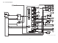
DMC-FT4/TS4 VIDEO/AUDIO PROCESS/ HDMI BLOCK DAIGRAM
57
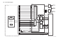
12.4. Sensor Block Diagram
IC3001
IC3002
(CDS/AGC/AD/TG)
(3V REG.)
VIN 4
CCD FPC
LENS UNIT
CCD
IC3101
CDS, AGC, A/D
CCD
Signal
V1A,V1B,V2,V3A,V3B,V4,V5A,V5B,V6,
V7A,V7B,V8,V8C,V8L,V8R,
V9C,V9L,V9R,V10,
MSUB,MSUBSW,SUB,SUBSW1,SUBSW2
H1A,H1B,H2,H3,H4,HL,RG,CCDOUT,VL,VH,
VDH,HHT
Q3101
REGULATOR
FP9003
5
FP9003
7
FP9003
42
FP9003
43
FP9003
41
FP9003
39
FP9003
40
FP9003
38
FP9003
37
FP9003
36
FP9003
35
FP9003
34
FP9003
32
FP9003
33
FP9003
31
FP9003
29
FP9003
30
FP9003
28
FP9003
26
FP9003
27
FP9003
25
FP9003
24
FP9003
23
FP9003
22
92
93
PW SE+3.4V
CCDOUT1
CCDOUT2
CDS
RGVDD 73
1 VOUT
CNT 3
31 V1A
32
41
33
34
42
V1B
V2
V3A
V3B
43
38
44
PW D+3V
POWER SECTION
IC1001 25
PW SE+2.1V
POWER SECTION
IC1001 36
IC3003
(2V REG.)
V4
AVDD 61
AVDD 62
36 V5B
35
POWER SECTION
IC1001 49
CNT 3
AVDD 63
V5A
LVDD 19
V6
1 VOUT
CLIVDD 66
V7B
VIN 4
DVDD 67
IOVDD 78
V8
V-DRIVER
37 V7A
IC6001 (VENUS ENGINE)
47 V8R
49
48
50
D0 8
V8L
D1 7
V8C
VGA
V9L
A/D
(14bit)
45
30
88
FP9003
15
89
FP9003
16
87
CLI
V-TIMING
CONTROL
HHT
SYNC
GENERATOR
VD
SUB
90
FP9003
10
91
FP9003
21
56 MSUB
FP9003
20
105
H3
POWER SECTION
PW_CCD_PLUS
POWER SECTION
PW_CCD_MINUS
POWER SECTION
PW_CCD_PLUS17
54
H2 S AFE SCK
3
J3 S AFE SDATA
2
R1 S AFE CSB
1
J4 S AFE CSA
HL
RG
MSUBSW
INTERNAL
REGISTORS
CSB
CSA
59
4
H4
SDATA
55
K5 CCD HD
H-DRIVER
SCK
FP9003
2
5
TIMING
GENERATOR
FP9003
11
FP9003
3
J2 CCD VD
H2
85
107
6
H1A
86
106
J1 CLK50 FCK
H1B
FP9003
14
FP9003
18
100
VDH
FP9003
12
FP9003
19
CCD0
V9C
HD
FP9003
13
K1-4,
L1-2
CCD5
40 V10
46
6bit
D5 9
52 V9R
51
D2 12
SUBSW1
SUBSW2
VH
VL
V17
FP9003
45
FP9003
44
FP9003
1
P3 CCD POWER SE
AD17 CCD THERMO
AA13 CCD POWER CTL
POWER SECTION
IC1620 1
PW D+1.8V
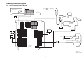
DMC-FT4/TS4 SENSOR BLOCK DIAGRAM
58
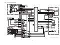
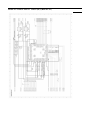
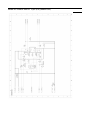
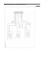
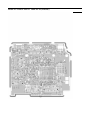
12.5. Lens Drive Block Diagram
TL8002
CL8002
T8001
F8002
D8002
3
F8001
C8001
4
(For
Flash
charge)
LAMP+
2
1
TL8003
FLASH
FP8001 FP9006
15,16,17,18
P8002
1
P8002
3
P8002
2
POWER SECTION
UNREG+
BAT+
+
ID BAT DQ
-
IC6001
BATTERY UNIT
(VENUS ENGINE)
BAT THERMO
MIC G FPC P.C.B.
IC8001
(ST TRG AMP)
1
LAMP-
L8001 3
FP8001 FP9006
4
FP8001 FP9006
1
FP8001 FP9006
6
FP8001 FP9006
7
FP8001 FP9006
5
FP8001 FP9006
9
SW 10
2
TL8001
FULL 9
START 6
Q8001
5
6
7
2
8
VCC 5
CL8009
3
IGBT_IN 7
4
AC18 BATT THERMO
Q9001
B3 ID BAT DQ
AC16 STB CHG LV
CATHODE
MOVIE LED CNT AB2
POWER SECTION
IC1001- 49
IC1001 59
+5V OUT
ANODE
2
CATHODE PWM U2
V1 ABS_FHP
W2 ABS_ZHP
SGPS SI AB6
SGPS SO AA8
IC9101
(LENS MOTOR DRIVE/SYSTEM IC)
GPS ON OFF U1
86
18
IC1090 3
VDD
PWMOUT
PWMA
FT9902
2
FT9902
3
FT9902
4
FT9902
5
FT9902
8
FT9902
1
FP9008 FT9901
5
FP9008 FT9901
6
FP9008 FT9901
7
FP9008 FT9901
8
FP9008 FT9901
11
FP9008 FT9901
4
GPS SRESET T1
3
FLASH CONDENSARE P.C.B.
D9901
MOVIE LED
IC3001 (CDS/AGC/AD/TG)
104 STROBE TRG
1
FP9008 FT9901
2,3
FP9008 FT9901
1
RL7003
GPS
MODULE
AB8 PWMFA
RL7004
21
47
CCD
FP9002
37
39
38
40
FP9002
FILTER
M
2
5
6
3
4
1
FZHP LED
48
12
4
BMP
22
BMN
19
AMP
16
AMN
13
LOGIC
41
AMP(Bch)
DAC
40
AMP(Ach)
37
PWMB
AA7 PWMFB
TOP FPC UNIT
XPWM
AC7 PWMXOIS
YPWM
AA9 PWMYOIS
CKG 27 SYS
FP9002
IRIS MOTOR
(STEPPING)
32
33
34
35
FP9002
M
SHUTTER MOTOR
(SOLENOID)
30
31
28
29
DI
58
56
FP9002
ZOOM MOTOR
(DC)
7
8
9
10
11
12
13
14
(COMPASS)
FP9001 FT6301
12
FP9001 FT6301
13
FP9001 FT6301
14
AD3
HDMI HSCL
AMP(Cch)
AB24
DMN
Y24 MCK24O
52
X6001
(24MHz)
50
CMN1
CMP2
CMP1
CMN2
MCK24I
HALL
SENSOR
22
21
19
YVYHO+
4 SCL
S6301
SHUTER BUTTON
XMP
5
GYROY0 AA14
43
7
6
42
1
69
72
XHN
YHOYINP
YHN
XVP
GYRO_Y
FP9001 FT6301
29
FP9001 FT6301
30,31
GYRO_X
VREF_Y
VREF_X
5 VOUT
IC6302
6 VREF
(GYRO
DET.)
5 VOUT
IC6301
6 VREF
(GYRO
DET.)
AMP(Xch)
REC
S6302
DAC
FP9001 FT6301
2
FP9001 FT6301
19
YMN
XINP
FP9001 FT6301
5
FP9001 FT6301
4
66
AMP(X/Ych)
YMP
4
(GYRO SENSOR)
DRIVER
46
38
2
XMN
1
IC7103
3
HALL
SENSOR
5 SI
FP9001 FT6301 SHUTER0
25
FP9001 FT6301 SHUTER1
15
SHUTTER1 AA1
AA24
GYROX0 AC14
FP9002
XDR15
XDR+
18
XHO+
25
XHO23
XV+
24
XV26
YDR16
YDR+
17
YV+
20
10 DRDY
CL9016
DMP
LENS UNIT
OIS UNIT
D6302
GPS WAKE UP
IC9301
AA11 DACLD
COMPASS DRDY
HDMI HSDA V23
MP
MN
FP9001 FT6301
22
FP9001 FT6301
23
AB9 DACDI
LD
DAC
M
IC1001 9
+3V OUT
AD8 DACCK
FOCUS MOTOR
(STEPPING)
M
GPS WAKEUP
AD4 CKG 27 CLK
CK
75
112
111
104
105
110
AMP
(HX)
AMP
(YX)
S6303
ADC
GYRO DAY
116
GYRO DAX 115
AMP
(HV)
YVP
107
SHUTTER0 83
AMP(Ych)
POWER
AMP
(YV)
REC
Y14
POWER
SW ON L
87
DMC-FT4/TS4 LENS DRIVE BLOCK DIAGRAM
59
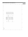
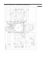
12.6. Power Block Diagram
CL1010
CL1001
FLASH MAIN
FP8001 FP9006
15-18
PW 5.2V
UNREG+
PW PS VCC
IC1001
(SWITCHING REGULATOR)
VOUT1A
VOUT1B
CH1
SYNC
BOOST
SW1A
SW1C
SW1B
REGISTERS
SW1D
PGND1A
DAC
PGND1B
POWER
SEQ
PVIN2A
TOP FPC UNIT
CH2
BUCK
BOOST
2.5MHz
OSC
PVIN2B
VOUT2A
VOUT2B
PGND2A
DAC
IC9101
POWER SW
PGND2B
PVIN3
S6303
FT6301 FP9001
19
CH3
SYNC
BUCK
87 POWER SW ON L
CL1003
OVERCUT 33
POWER CTL SW 35
1
EN
SW3
4 VIN
VOUT 1
3 CE
GND 2
PW LDO+5V
CL1020
59
60
PW AF+3.4V
61
IC1210 (REGULATOR)
62
63
2 VIN
PW SE+3.4V
CL1211
GND 4
64
57
3 EN1 VOUT1 5
58
1 EN2 VOUT2 6
PW SD+3V
PW A+3.1V
CL1210
55
CL1080
56
49
PW D+3V
CL1620
50
47
PW D+1.8V
48
Q1620
REF
0.5V
(SYSTEM IC)
CL1110
IC1110 (REGULATOR)
(OUTPUT
CONTROL)
46
45
QR1620
3 D2 D1 6
(SIGNAL
CONTROL)
2 G1 S2 4
5 G2 S1 1
ENABLE
BUFFER
FB3
DAC
PGND3
24
44
CL1030
IC6001
(VENUS ENGINE)
PVIN45
VH4
POWER SW ON AA23
UVLO
RTC
54 POWER SW ON
CH4
84 POWER ON H
POWER ON H AB1
SW4
FB4
PGND4
CH8
LDO
QR1001
PVIN8
VOUT8
DAC
43
PW CCD PLUS
41
23
40
26
D1041
CL1041
1
3
2
25
(SIGNAL
CONTROL)
IC1620 (REGULATOR)
2
B1
3 C2
SW5
DSCG5
E2 4
CH5
SW UNREG Y15
CH6
SYNC
BUCK
S HDMI HSCL AB24
6
S HDMI HSDA Y23
7
SCL
SDA
I2C
INTERFACE
DAC
39
4 VIN
VOUT 1
32
3 CE
GND 2
FB5
22
REF5 21
PGND5
38
PVIN6
SW6
FB6
PGND6
PW D+1.2V
CL1040
42
PW CCD PLUS17
D1042
CL1050
PW CCD MINUS
CL1060
37
36
PW SE+2.1V
20
35
CL1007
BL PWM
U1
CL1070
17 ISET7
SW7
CH7
OVP7
LSTR7
BLGND7
DAC
PGND7
VBATT
34
CL1071
PW BL MINUS
18
CL1091
27
33
8
PW LED+3.2V
IC1090
(SW REGULATOR)
UVLO SYSTEM
CH9
KEEP ALIVE
LDO
VREGO
PW BL VDD
19
9
VOUT 3
6 VIN
4 CE
CL1090
PW GPS VDD
LX 1
VSS 2
VSS 5
HDMI5V CTL B7
SD3V CTL R3
DMC-FT4/TS4 POWER BLOCK DIAGRAM
60
13 Wiring Connection Diagram
13.1. Interconnection Schematic Diagram
1
FT9901
MIC G FPC P.C.B.
(FOIL SIDE)
BATT+
BATT+
BATT+
BATT+
NC
BATTBATTBATTBATTSTROBE_TRG
A_GND
STB_PWM_OUT
STB_CHG_LV
IGBT_VCC
BATT_THERMO
UNREG_GND
UNREG_GND
ID_BAT_DQ
15
18
17
16
15
14
13
12
11
10
9
8
7
6
5
4
3
2
1
1
2
3
4
P8002
BAT+
BAT_THERMO
ID_BAT_DQ
BAT-
FLASH CON P.C.B.
(FOIL SIDE)
FP8001
: (COMPONENT SIDE)
BATTERY
FP9008
ANODE
1
CATHODDE
2
CATHODDE
3
GPS_WAKEUP
4
GPS_SRESET
5
S_GPS_SI
6
S_GPS_SO
7
GPS_ON_OFF
8
GPS_GND
9
GPS_GND
10
PW_GPS_VDD
11
MIC_GND
12
MIC_GND
13
G_MIC_IN
14
G_MIC_IN
15
TOP FPC UNIT
(FOIL SIDE)
VREF_X
GYRO_GND
PW_GY3R1V
D_GND
GPS_WAKEUP
NC
NC
D_GND
S_HDMI_HSCL
COMPASS_DRDY
D_GND
PW_D3V
GYRO_GND
VREF_Y
REC
FP9006
ID_BAT_DQ
1
UNREG_GND
2
UNREG_GND
3
BATT_THERMO
4
IGBT_VCC
5
STB_CHG_LV
6
STB_PWM_OUT
7
A_GND
8
STROBE_TRG
9
BATT10
BATT11
BATT12
BATT13
NC
14
BATT+
15
BATT+
16
BATT+
17
BATT+
18
FP9001
VREF_X
31
G_GYRO_X
29
GYRO_GND
27
SHUTTER_0
25
PW_LED3R2V
23
NC
21
POWER_ON_L
19
NC
17
SHUTTER_1
15
S_HDMI_HSDA
13
D_GND
11
PW_D3V
9
GYRO_GND
7
G_GYRO_Y
5
PW_GY3R1V
3
DGND
1
FT9902
GPS
Module
30
28
26
24
22
20
18
16
14
12
10
8
6
4
2
FT6301
LENS
UNIT
CCD
UNIT
FP9002
FAN(FMAN)
1
FAP(FMAP)
3
FBN(FMBN)
5
ZMAN
7
ZMBP
9
ZMAP
11
ZMBP
13
X_DRV-(X_DR-)
15
X_DRV+(Y_DR+)
17
Y_VO-(YHO-)
19
Y_VO+(YHO+)
21
X_VO-(XHO-)
23
X_VO+(XHO+)
25
NC
27
29 SH+(SHUT_OUT2)
31 SH-(SHUT_OUT1)
IRIS+
33
IRIS35
37 LED_CONT(FHP_LED)
39 LED_CONT(ZHP_LED)
ENC_Vcc(D2R9V)
41
FP9003
1 CCD_POWER_CTL
3
VH
5
CCD_OUT1
7
CCD_OUT2
9
CCD_GND
11
HL
13
H1B
15
H1A
17
CCD_GND
19
SUBSW1
21
MSUB
23
HHT
25
V10
27
V9C
29
V8L
31
V8R
33
V7A
35
V6
37
V5B
39
V3A
41
V2
43
V1B
45 CCD_POWER_SE
1
FBP(FMBP)
FAP(FMAP)
FBN(FMBN)
ZMAN
ZMBP
ZMAP
ZMBP
X_DRV-(Y_DR-)
X_DRV+(Y_DR+)
Y_VH+(YV+)
Y_VH-(YV-)
X_VH+(XV+)
X_VH-(XV-)
SH+(SHUT_OUT2)
SH-(SHUT_OUT1)
IRIS+
IRISENC_Vcc(D2R9V)
ABS(FHP)
ABS(ZHP)
2
4
6
8
10
12
14
16
18
20
22
24
26
28
30
32
34
36
38
40
VL
CCD_GND
CCD_GND
CCD_GND
RG
H3
H4
H2
SUBSW2
MSUBSW
SUB
VDH
V9R
V9L
V8C
V8
V7B
V5A
V4
V3B
V1A
CCD_TERMO
2
4
6
8
10
12
14
16
18
20
22
24
26
28
30
32
34
36
38
40
42
44
(2)
FP9007
1
3
5
7
9
11
13
15
17
19
21
23
25
27
29
31
33
35
37
39
SDATA
LOAD
HD
CLK
D7
D5
D3
D1
VDD1
VDD
GND
CP1B
VOUT
CP2A
CP3A
CP4B
VGL
CP5B
VCOML
VCOMH
SCLK
RESET
VD
GND
D6
D4
D2
D0
NC
VCORE
VSH
CP1A
CP2B
CP3B
VGH
CP4A
GND
CP5A
VCL
G_SP_POS
G_SP_POS
NC
NC
G_SP_NEG
G_SP_NEG
TELE_WIDE
PLAY_SW
MODE
UP
RIGHT
MENU
LEFT
DOWN
DELETE
DISPLAY
D_GND
D_GND
D_GND
MAIN P.C.B.
(FOIL SIDE)
NC
NC
BL_MINUS
BL_VDD
2
4
6
8
10
12
14
16
18
20
22
24
26
28
30
32
34
36
38
31
(30)
LCD UNIT
SPEAKER
FP9004
1
2
3
4
5
6
7
8
9
10
11
12
13
14
15
16
17
18
19
1
FT6401
19
REAR
OPERATION
FPC P.C.B.
(FOIL SIDE)
FP9005
1
2
3
4
DMC-FT4/TS4
INTERCONNECTION
SCHEMATIC DIAGRAM
61
Model No. : DMC-FT4/TS4
Schematic Diagram Note
Model No. : DMC-FT4/TS4
Parts List Note
Model No. : DMC-FT4/TS4
Power (P) (Main P.C.B.)
Model No. : DMC-FT4/TS4
Jack (J) (Main P.C.B.)
Model No. : DMC-FT4/TS4
Sensor (SE) (Main P.C.B.)
Model No. : DMC-FT4/TS4
LCD (L) (Main P.C.B.)
Model No. : DMC-FT4/TS4
Digital (D) (Main P.C.B.)
Model No. : DMC-FT4/TS4
Accelerator Press (AP) (Main P.C.B.)
Model No. : DMC-FT4/TS4
Gyro (GY) (Main P.C.B.)
Model No. : DMC-FT4/TS4
System Driver (SY) (Main P.C.B.)
Model No. : DMC-FT4/TS4
Main CN (MC) (Main P.C.B.)
Model No. : DMC-FT4/TS4
HDMI (H) (Main P.C.B.)
Model No. : DMC-FT4/TS4
Flash CON (Flash CON P.C.B.)
Model No. : DMC-FT4/TS4
Top FPC (Top FPC P.C.B.)
Model No. : DMC-FT4/TS4
Rear OPE FPC (Rear OPE FPC P.C.B.)
Model No. : DMC-FT4/TS4
MIC G FPC (MIC G FPC P.C.B.)
Model No. : DMC-FT4/TS4
Main P.C.B. (Component Side)
Model No. : DMC-FT4/TS4
Main P.C.B. (Foil Side)
Model No. : DMC-FT4/TS4
Flash CON P.C.B. (Component Side)
Model No. : DMC-FT4/TS4
Flash CON P.C.B. (Foil Side)
Model No. : DMC-FT4/TS4
Top FPC P.C.B. (Foil Side)
Model No. : DMC-FT4/TS4
Rear OPE FPC P.C.B. (Foil Side)
Model No. : DMC-FT4/TS4
MIC G FPC P.C.B. (Foil Side)
Model No. : DMC-FT4/TS4
Safety
Ref.
No.
Part No.
C1001
C1002
C1003
C1004
C1010
C1011
C1020
C1030
C1040
C1041
C1042
C1043
C1050
C1051
C1060
C1070
C1071
C1080
C1090
C1091
C1110
C1210
C1211
C1620
C2101
C2102
C3000
C3003
C3004
C3005
C3006
C3007
C3008
C3009
C3010
C3011
C3012
C3013
C3014
C3015
C3016
C3017
C3018
C3019
C3020
C3021
C3022
C3023
C3031
C3032
C3033
C3034
C3040
C4001
C4002
C4003
C4004
C4005
C4006
C4007
C4008
C4009
F1H0J106A009
F1J1A106A043
F1G0J1050007
F1G0J1050007
F1J1A106A043
F1J1A106A043
F1J0J2260004
F1J1A106A043
F1J1C106A059
F1G1H821A571
F1G1C1030008
F1H1H104A913
F1J1C1060001
F1G1E471A059
F1J1A106A043
F1J1E4750002
F1G0J1050007
F1H1A225A051
F1H0J106A009
F1G0J1050007
F1H1A225A051
ECJ1VB1A105K
F1H0J106A009
F1H1A225A051
ECJ1VB1A105K
F1G1A104A012
F3Z0E1070001
F1G1A104A012
F1G1A104A012
F1H0J106A009
F1J1A106A043
F1J1A106A043
F1H1C105A097
F1H1C105A097
F1H1E105A116
F1G1A104A012
F1H0J1060009
F1H0J1060009
F1H0J1060009
F1G1C1030008
F1G1A104A012
F1G1A104A012
F1G1A104A012
F1G1A104A012
F1G1A104A012
F1G1A104A012
F1H1H104A913
F1G0J1050007
ECJ1VB0J105K
ECJ1VB0J105K
ECJ1VB0J105K
ECJ1VB0J105K
F1G1A104A012
ECJ1VB1A105K
F1G0J1050007
F1H0J2250008
F1G0J1050007
F1H1C105A097
F1H1C105A097
F1H1E105A116
F1H1C105A097
F1H1C105A097
Parts List
Part Name & Description
C.CAPACITOR
C.CAPACITOR
C.CAPACITOR
C.CAPACITOR
C.CAPACITOR
C.CAPACITOR
C.CAPACITOR
C.CAPACITOR
C.CAPACITOR
C.CAPACITOR
C.CAPACITOR
C.CAPACITOR
C.CAPACITOR
C.CAPACITOR
C.CAPACITOR
C.CAPACITOR
C.CAPACITOR
C.CAPACITOR
C.CAPACITOR
C.CAPACITOR
C.CAPACITOR
C.CAPACITOR
C.CAPACITOR
C.CAPACITOR
C.CAPACITOR
C.CAPACITOR
CAPACITOR
C.CAPACITOR
C.CAPACITOR
C.CAPACITOR
C.CAPACITOR
C.CAPACITOR
C.CAPACITOR
C.CAPACITOR
C.CAPACITOR
C.CAPACITOR
C.CAPACITOR
C.CAPACITOR
C.CAPACITOR
C.CAPACITOR
C.CAPACITOR
C.CAPACITOR
C.CAPACITOR
C.CAPACITOR
C.CAPACITOR
C.CAPACITOR
C.CAPACITOR
C.CAPACITOR
C.CAPACITOR
C.CAPACITOR
C.CAPACITOR
C.CAPACITOR
C.CAPACITOR
C.CAPACITOR
C.CAPACITOR
C.CAPACITOR
C.CAPACITOR
C.CAPACITOR
C.CAPACITOR
C.CAPACITOR
C.CAPACITOR
C.CAPACITOR
CH
CH
CH
CH
CH
CH
CH
CH
CH
CH
CH
CH
CH
CH
CH
CH
CH
CH
CH
CH
CH
CH
CH
CH
CH
CH
6.3V 10U
10V 10U
6.3V 1U
6.3V 1U
10V 10U
10V 10U
6.3V 22U
10V 10U
16V 10U
25V 820P
16V 0.01U
50V 0.1U
16V 10U
25V 470P
10V 10U
25V 4.7U
6.3V 1U
10V 2.2U
6.3V 10U
6.3V 1U
10V 2.2U
10V 1U
6.3V 10U
10V 2.2U
10V 1U
10V 0.1U
CH
CH
CH
CH
CH
CH
CH
CH
CH
CH
CH
CH
CH
CH
CH
CH
CH
CH
CH
CH
CH
CH
CH
CH
CH
CH
CH
CH
CH
CH
CH
CH
CH
CH
CH
10V 0.1U
10V 0.1U
6.3V 10U
10V 10U
10V 10U
16V 1U
16V 1U
25V 1U
10V 0.1U
6.3V 10U
6.3V 10U
6.3V 10U
16V 0.01U
10V 0.1U
10V 0.1U
10V 0.1U
10V 0.1U
10V 0.1U
10V 0.1U
50V 0.1U
6.3V 1U
6.3V 1U
6.3V 1U
6.3V 1U
6.3V 1U
10V 0.1U
10V 1U
6.3V 1U
6.3V 2.2U
6.3V 1U
16V 1U
16V 1U
25V 1U
16V 1U
16V 1U
Q'ty
1
1
1
1
1
1
1
1
1
1
1
1
1
1
1
1
1
1
1
1
1
1
1
1
1
1
1
1
1
1
1
1
1
1
1
1
1
1
1
1
1
1
1
1
1
1
1
1
1
1
1
1
1
1
1
1
1
1
1
1
1
1
Remarks
Model No. : DMC-FT4/TS4
Safety
Ref.
No.
Part No.
C4010
C4011
C4012
C4013
C4014
C4015
C5002
C5003
C5005
C5006
C5007
C5009
C5010
C5012
C5013
C5023
C6001
C6002
C6003
C6008
C6009
C6012
C6014
C6015
C6016
C6017
C6018
C6019
C6020
C6021
C6022
C6023
C6024
C6025
C6026
C6027
C6030
C6032
C6033
C6036
C6037
C6038
C6044
C6047
C6302
C6303
C6304
C6305
C7001
C7003
C7006
C7007
C7008
C7009
C7010
C7011
C7014
C7023
C7104
C7105
C7106
C7107
F1H1A225A051
F1H0J2250008
F1H1A225A051
F1H0J2250008
F1G0J1050007
F1G0J1050007
F1G1A104A012
F1G1A104A012
F1G0J1050007
F1G0J1050007
F1G0J1050007
F1H0J4750005
F1G1A104A012
F1G0J1050007
F1G0J1050007
ECJ0EC1H101J
F1G1A104A012
F1G1A104A012
F1G1A104A012
F1G1C1030008
F1G1C1030008
F1G0J1050007
F1H0J106A009
F1G0J1050007
F1G0J1050007
F1H0J1060009
F1G1C1030008
F1G0J1050007
F1G1A104A012
ECJ0EC1H100D
ECJ0EC1H100D
F1H0J106A009
F1G1A104A012
F1G0J1050007
F1G1A104A012
F1G1A104A012
F1G0J1050007
F1G1A104A012
F1G0J1050007
F1G1A104A012
F1H0J106A009
F1G0J1050007
F1G1A104A012
F1H0J106A009
F1H0J4750005
ECJ1VB1H102K
F1H0J4750005
F1G1H1020008
ECJ1VB1A105K
ECJ1VB1A105K
F1G1C1030008
F1G1C1030008
F1G1C1030008
F1G1C1030008
F1G0J1050007
F1G0J1050007
F1H0J106A009
F1H0J106A009
F1G1A104A012
F1G1H221A551
F1G1H221A551
F1G0J1050007
Parts List
Part Name & Description
C.CAPACITOR
C.CAPACITOR
C.CAPACITOR
C.CAPACITOR
C.CAPACITOR
C.CAPACITOR
C.CAPACITOR
C.CAPACITOR
C.CAPACITOR
C.CAPACITOR
C.CAPACITOR
C.CAPACITOR
C.CAPACITOR
C.CAPACITOR
C.CAPACITOR
C.CAPACITOR
C.CAPACITOR
C.CAPACITOR
C.CAPACITOR
C.CAPACITOR
C.CAPACITOR
C.CAPACITOR
C.CAPACITOR
C.CAPACITOR
C.CAPACITOR
C.CAPACITOR
C.CAPACITOR
C.CAPACITOR
C.CAPACITOR
C.CAPACITOR
C.CAPACITOR
C.CAPACITOR
C.CAPACITOR
C.CAPACITOR
C.CAPACITOR
C.CAPACITOR
C.CAPACITOR
C.CAPACITOR
C.CAPACITOR
C.CAPACITOR
C.CAPACITOR
C.CAPACITOR
C.CAPACITOR
C.CAPACITOR
C.CAPACITOR
C.CAPACITOR
C.CAPACITOR
C.CAPACITOR
C.CAPACITOR
C.CAPACITOR
C.CAPACITOR
C.CAPACITOR
C.CAPACITOR
C.CAPACITOR
C.CAPACITOR
C.CAPACITOR
C.CAPACITOR
C.CAPACITOR
C.CAPACITOR
C.CAPACITOR
C.CAPACITOR
C.CAPACITOR
CH
CH
CH
CH
CH
CH
CH
CH
CH
CH
CH
CH
CH
CH
CH
CH
CH
CH
CH
CH
CH
CH
CH
CH
CH
CH
CH
CH
CH
CH
CH
CH
CH
CH
CH
CH
CH
CH
CH
CH
CH
CH
CH
CH
CH
CH
CH
CH
CH
CH
CH
CH
CH
CH
CH
CH
CH
CH
CH
CH
CH
CH
10V 2.2U
6.3V 2.2U
10V 2.2U
6.3V 2.2U
6.3V 1U
6.3V 1U
10V 0.1U
10V 0.1U
6.3V 1U
6.3V 1U
6.3V 1U
6.3V 4.7U
10V 0.1U
6.3V 1U
6.3V 1U
50V 100P
10V 0.1U
10V 0.1U
10V 0.1U
16V 0.01U
16V 0.01U
6.3V 1U
6.3V 10U
6.3V 1U
6.3V 1U
6.3V 10U
16V 0.01U
6.3V 1U
10V 0.1U
50V 10P
50V 10P
6.3V 10U
10V 0.1U
6.3V 1U
10V 0.1U
10V 0.1U
6.3V 1U
10V 0.1U
6.3V 1U
10V 0.1U
6.3V 10U
6.3V 1U
10V 0.1U
6.3V 10U
6.3V 4.7U
50V 1000P
6.3V 4.7U
50V 1000P
10V 1U
10V 1U
16V 0.01U
16V 0.01U
16V 0.01U
16V 0.01U
6.3V 1U
6.3V 1U
6.3V 10U
6.3V 10U
10V 0.1U
50V 220P
50V 220P
6.3V 1U
Q'ty
Remarks
1
1
1
1
1
1
1
1
1
1
1
1
1
1
1
1
1
1 EE,GC,GN,P,PC,PU,GH,GD
1 EG,EP,EF,EB
1
1
1
1
1
1
1
1
1
1
1
1
1
1
1
1
1
1
1
1
1
1
1
1
1
1
1
1
1
1
1
1
1
1
1
1
1
1
1
1
1
1
1
Model No. : DMC-FT4/TS4
Safety
Ref.
No.
C7108
C7109
C7110
C8003
C8004
C8005
C8006
C8010
C9001
C9003
C9004
C9005
C9006
C9007
C9008
C9009
C9031
C9101
C9102
C9103
C9104
C9105
C9106
C9111
C9201
C9202
C9301
C9601
C9602
C9603
C9607
C9608
C9609
C9616
CX6001
D1010
D1040
D1041
D1042
D1050
D1070
D3001
D6302
D8002
D9119
D9601
D9901
ET2001
ET2002
ET2003
ET2004
F2001
F8001
F8002
FL9601
FL9602
FL9603
FP8001
FP9001
FP9002
FP9003
FP9004
Part No.
F1G0J1050007
F1G1H4710004
F1G1H4710004
F1G1H220A565
F1G0J1050007
F1J0J106A020
F1K2E4730005
F1G1H101A565
F1H0J106A009
ECJ0EC1H100D
ECJ0EC1H100D
ECJ0EC1H100D
ECJ0EC1H100D
F1H0J106A009
F1G1A104A012
ECJ0EC1H100D
F1G1A104A012
F1G1H1020008
F1G0J1050007
ECJ0EC1H100D
ECJ0EC1H120J
F1G0J1050007
F1G0J1050007
ECJ1VB1A105K
F1G1A104A012
F1G1A104A012
F1G1A104A012
F1H0J1060009
F1H0J1060009
F1H0J1060009
F1G1A104A012
F1G1A104A012
F1G1A104A012
F1G1A104A012
F5A84103A020
B0JCMD000066
B0JCFC000001
B0JDCE000013
B0BC018A0265
B0JCFC000001
B0JCFC000001
B0ACCJ000052
B3ABB0000150
B0ECFR000003
B0ADDH000014
B0JCDD000019
B3AFB0000328
K4ZZ01000208
K4ZZ01000208
K4ZZ01000208
K4ZZ01000208
K5H1522A0018
ERBSE2R00U
ERBSE1R25U
J0ZZB0000146
J0ZZB0000146
F1H0J105A037
K1MY18BA0370
K1MY31BA0235
K1MY41BA0235
K1MY45BA0235
K1MY19BA0235
Parts List
Part Name & Description
C.CAPACITOR CH 6.3V 1U
C.CAPACITOR CH 50V 470P
C.CAPACITOR CH 50V 470P
C.CAPACITOR CH 50V 22P
C.CAPACITOR CH 6.3V 1U
C.CAPACITOR CH 6.3V 10U
C.CAPACITOR 250V 0.047U
C.CAPACITOR CH 50V 100P
C.CAPACITOR CH 6.3V 10U
C.CAPACITOR CH 50V 10P
C.CAPACITOR CH 50V 10P
C.CAPACITOR CH 50V 10P
C.CAPACITOR CH 50V 10P
C.CAPACITOR CH 6.3V 10U
C.CAPACITOR CH 10V 0.1U
C.CAPACITOR CH 50V 10P
C.CAPACITOR CH 10V 0.1U
C.CAPACITOR CH 50V 1000P
C.CAPACITOR CH 6.3V 1U
C.CAPACITOR CH 50V 10P
C.CAPACITOR CH 50V 12P
C.CAPACITOR CH 6.3V 1U
C.CAPACITOR CH 6.3V 1U
C.CAPACITOR CH 10V 1U
C.CAPACITOR CH 10V 0.1U
C.CAPACITOR CH 10V 0.1U
C.CAPACITOR CH 10V 0.1U
C.CAPACITOR CH 6.3V 10U
C.CAPACITOR CH 6.3V 10U
C.CAPACITOR CH 6.3V 10U
C.CAPACITOR CH 10V 0.1U
C.CAPACITOR CH 10V 0.1U
C.CAPACITOR CH 10V 0.1U
C.CAPACITOR CH 10V 0.1U
CAPACITOR
DIODE
DIODE
DIODE
DIODE
DIODE
DIODE
DIODE
DIODE
DIODE
DIODE
DIODE
DIODE
EARTH SPRING
EARTH SPRING
EARTH SPRING
EARTH SPRING
FUSE 32V 1.5A
FUSE 32V 2.0A
FUSE 32V 1.25A
FILTER
FILTER
C.CAPACITOR CH 6.3V 1U
CONNECTOR 18P
CONNECTOR 31P
CONNECTOR 41P
CONNECTOR 45P
CONNECTOR 19P
Q'ty
1
1
1
1
1
1
1
1
1
1
1
1
1
1
1
1
1
1
1
1
1
1
1
1
1
1
1
1
1
1
1
1
1
1
1
1
1
1
1
1
1
1
1
1
1
1
1
1
1
1
1
1
1
1
1
1
1
1
1
1
1
1
Remarks
[PAVCX]
[PAVCX]
[PAVCX]
[PAVCX]
[PAVCX]
E.S.D.
E.S.D.
E.S.D.
E.S.D.
E.S.D.
E.S.D.
E.S.D.
E.S.D.
E.S.D. [PAVCX]
E.S.D.
E.S.D.
E.S.D.
[PAVCX]
[PAVCX]
[PAVCX]
Model No. : DMC-FT4/TS4
Safety
Ref.
No.
FP9005
FP9006
FP9007
FP9008
IC1001
IC1090
IC1110
IC1210
IC1620
IC3001
IC3002
IC3003
IC6001
IC6002
IC6301
IC6302
IC7103
IC8001
IC9001
IC9101
IC9201
IC9202
Part No.
K1MN04BA0162
K1MY18BA0370
K1MY39BA0235
K1MY15BA0235
C0DBAYY01047
C0DBAYY00946
C0DBGYY00821
C0DBGYY00851
C0CBCYY00056
C1AB00003533
C0DBGYY00798
C0DBGYY00777
MN89513
RS10320
L2ES00000022
L2ES00000021
C0ABHA000070
C0ZBZ0001817
C0JBAU000053
C1AB00003449
VUEALLPT048
VUEALLPT047
Parts List
Part Name & Description
CONNECTOR
CONNECTOR
CONNECTOR
CONNECTOR
IC
IC
IC
IC
IC
IC
IC
IC
IC
IC
IC
IC
IC
IC
IC
IC
IC
IC
4P
18P
39P
15P
IC9301 ------
IC
IC9601
JK2001
JK2004
L1010
L1020
L1030
L1040
L1050
L1060
L1070
L1090
L2001
L3002
L3003
L3004
L7001
L7101
L8001
L9601
L9602
LB1001
LB2001
LB2002
LB2003
LB2004
LB6001
LB6003
LB6004
LB6040
LB6084
LB9000
LB9001
LB9002
LB9003
LB9601
LB9602
LB9603
LB9604
IC
JACK, AV/USB
JACK
CHIP INDUCTOR
CHIP INDUCTOR
CHIP INDUCTOR
CHIP INDUCTOR
CHIP INDUCTOR
CHIP INDUCTOR
CHIP INDUCTOR
CHIP INDUCTOR
FILTER
CHIP INDUCTOR
CHIP INDUCTOR
CHIP INDUCTOR
CHIP INDUCTOR
CHIP INDUCTOR
CHIP INDUCTOR
CHIP INDUCTOR
CHIP INDUCTOR
FILTER
FILTER
FILTER
FILTER
FILTER
FILTER
FILTER
FILTER
FILTER
FILTER
FILTER
FILTER
FILTER
FILTER
FILTER
FILTER
FILTER
FILTER
MN864712P-EB
K1FB108E0008
K1FY119EA020
G1C4R7MA0428
G1C4R7MA0428
G1C4R7MA0328
G1C100MA0393
ELLVGG4R7NC
G1C4R7MA0328
G1C100MA0428
G1C4R7MA0388
J0ZZB0000142
G1C2R2MA0211
G1C100MA0410
G1C100KA0115
G1C100MA0410
G1C100MA0410
G5F1A0000026
G1C100KA0138
G1C100KA0138
J0JHC0000048
J0JCC0000415
J0JCC0000415
J0JCC0000415
J0JCC0000415
J0JCC0000317
J0JCC0000412
J0JCC0000412
J0JCC0000412
J0JDC0000105
J0JDC0000099
J0JDC0000099
J0JDC0000099
J0JDC0000099
J0JYC0000061
J0JYC0000061
J0JYC0000061
J0JYC0000061
Q'ty
1
1
1
1
1
1
1
1
1
1
1
1
1
1
1
1
1
1
1
1
1
1
4.7UH
4.7UH
4.7UH
10UH
4.7UH
4.7UH
10UH
4.7UH
2.2UH
10UH
10UH
10UH
10UH
10UH
10UH
Remarks
E.S.D.
E.S.D.
E.S.D.
E.S.D.
E.S.D.
E.S.D.
E.S.D.
E.S.D.
E.S.D.
E.S.D.
E.S.D.
E.S.D.
E.S.D.
E.S.D. [PAVCX]
E.S.D.
E.S.D.
E.S.D.
E.S.D.
E.S.D. (NOT SUPPLIED) REPLACE WITH VEP50
1
082A.
1 E.S.D.
1
1
1
1
1
1
1
1
1
1
1
1
1
1
1
1
1 [PAVCX]
1
1
1
1
1
1
1
1
1
1
1
1
1
1
1
1
1
1
1
1
Model No. : DMC-FT4/TS4
Safety
Ref.
No.
LB9605
M9901
P8002
P9007
Q1620
Q8001
Q9001
QR1001
QR1620
QR6001
R1002
R1003
R1008
R1041
R1042
R1043
R1044
R1045
R1046
R1051
R1052
R1061
R1062
R1071
R1072
R1073
R1122
R1622
R2001
R2002
R2003
R2005
R3007
R3009
R3030
R4001
R5012
R5013
R6004
R6006
R6008
R6009
R6010
R6011
R6012
R6014
R6018
R6019
R6020
R6021
R6028
R6030
R6033
R6034
R6037
R6039
R6047
R6050
R6053
R6057
R6058
R6059
Part No.
J0JCC0000412
L0CBAA000014
K4ZZ04000060
K1NA09E00098
B1CFJC000009
B1JBLP000038
B1HFCFA00035
B1GKCFGN0003
B1GBCFJN0041
B1GBCFNL0020
ERJ2RHD183
ERJ2RHD223
D0GB1R0JA057
ERJ2RKD204
ERJ2RKD334
ERJ2RHD822X
ERJ2RHD104
ERJ2RHD103
ERJ2RKD334
ERJ2RKD124
ERJ2RHD303
ERJ2RHD512
ERJ2RHD162X
ERJ2RHD222
ERJ2RHD753
ERJ2RHD153X
ERJ2GEJ473
ERJ2GEJ104
ERJ2GEJ750
ERJ2GEJ561
ERJ2GEJ102X
ERJ2GEJ102X
D0YAR0000007
ERJ2GEJ100
ERJ2GEJ103
ERJ2GEJ224
D0YAR0000007
ERJ2GEJ222
ERJ2GEJ103
ERJ2RKF5901
ERJ2GEJ105
ERJ2GEJ821
ERJ2GEJ103
ERJ2GEJ101
ERJ2GEJ103
ERJ2RKD330
ERJ2RKF1183
ERJ2RHD222
ERJ2RHD122
ERJ2GEJ473
ERJ2RHD561
ERJ2GEJ104
ERJ2GEJ220
ERJ2GEJ220
ERJ2GEJ102X
ERJ2GEJ102X
D0YAR0000007
ERJ2GEJ103
ERJ2GEJ101
ERJ2GEJ101
ERJ2RKF1000
ERJ2RKF1000
Parts List
Part Name & Description
FILTER
MICROPHONE UNITS
CONNECTOR 4P
SD CARD CONNECTOR
TRANSISTOR
TRANSISTOR
TRANSISTOR-RESISTOR
TRANSISTOR-RESISTOR
TRANSISTOR-RESISTOR
TRANSISTOR-RESISTOR
M.RESISTOR CH 1/16W
M.RESISTOR CH 1/16W
M.RESISTOR CH 1/10W
M.RESISTOR CH 1/16W
M.RESISTOR CH 1/16W
M.RESISTOR CH 1/16W
M.RESISTOR CH 1/16W
M.RESISTOR CH 1/16W
M.RESISTOR CH 1/16W
M.RESISTOR CH 1/16W
M.RESISTOR CH 1/16W
M.RESISTOR CH 1/16W
M.RESISTOR CH 1/16W
M.RESISTOR CH 1/16W
M.RESISTOR CH 1/16W
M.RESISTOR CH 1/16W
M.RESISTOR CH 1/16W
M.RESISTOR CH 1/10W
M.RESISTOR CH 1/10W
M.RESISTOR CH 1/16W
M.RESISTOR CH 1/16W
M.RESISTOR CH 1/16W
M.RESISTOR CH 1/10W
M.RESISTOR CH 1/10W
M.RESISTOR CH 1/10W
M.RESISTOR CH 1/10W
M.RESISTOR CH 1/10W
M.RESISTOR CH 1/10W
M.RESISTOR CH 1/10W
M.RESISTOR CH 1/16W
M.RESISTOR CH 1/10W
M.RESISTOR CH 1/10W
M.RESISTOR CH 1/10W
M.RESISTOR CH 1/10W
M.RESISTOR CH 1/10W
M.RESISTOR CH 1/16W
M.RESISTOR CH 1/16W
M.RESISTOR CH 1/16W
M.RESISTOR CH 1/16W
M.RESISTOR CH 1/16W
M.RESISTOR CH 1/16W
M.RESISTOR CH 1/10W
M.RESISTOR CH 1/16W
M.RESISTOR CH 1/16W
M.RESISTOR CH 1/16W
M.RESISTOR CH 1/16W
M.RESISTOR CH 1/10W
M.RESISTOR CH 1/10W
M.RESISTOR CH 1/10W
M.RESISTOR CH 1/10W
M.RESISTOR CH 1/16W
M.RESISTOR CH 1/16W
18K
22K
1
200K
330K
8.2K
100K
10K
330K
120K
30K
5.1K
1.6K
2.2K
75K
15K
47K
100K
75
560
1K
1K
0
10
10K
220K
0
2.2K
10K
5.9K
1M
820
10K
100
10K
33
118K
2.2K
1.2K
47K
560
100K
22
22
1K
1K
0
10K
100
100
1K
1K
Q'ty
1
1
1
1
1
1
1
1
1
1
1
1
1
1
1
1
1
1
1
1
1
1
1
1
1
1
1
1
1
1
1
1
1
1
1
1
1
1
1
1
1
1
1
1
1
1
1
1
1
1
1
1
1
1
1
1
1
1
1
1
1
1
Remarks
[PAVCX]
E.S.D.
E.S.D. [PAVCX]
E.S.D.
E.S.D.
E.S.D.
E.S.D.
EG,EP,EF,EB
Model No. : DMC-FT4/TS4
Safety
Ref.
No.
Part No.
R6060
R6061
R6062
R6063
R6071
R6079
R6085
R6401
R6402
R6410
R6411
R6412
R6413
R6414
R6420
R7002
R7007
R7009
R7021
R7101
R7102
R7103
R7104
R7105
R7106
R7109
R7110
R7111
R7112
R8001
R8002
R8003
R8004
R8006
R8008
R8009
R8010
R9001
R9003
R9004
R9005
R9006
R9007
R9008
R9012
R9014
R9030
R9035
R9101
R9102
R9103
R9106
R9107
R9108
R9109
R9120
R9607
R9608
R9609
R9610
R9617
R9618
ERJ2RKF1000
ERJ2RKF1000
ERJ2RKF1000
ERJ2RKF1000
ERJ2GEJ102X
ERJ2GEJ161
ERJ2GEJ103
ERJ2GEJ123
ERJ2GEJ223
ERJ2GEJ680
ERJ2GEJ680
ERJ2GEJ680
ERJ2GEJ680
ERJ2GEJ102X
D0YAR0000007
ERJ2RKD680
ERJ2RKD680
D0HA1R0ZA005
ERJ2RHD822X
ERJ2RKD564
ERJ2RKD564
ERJ2RHD472X
ERJ2RHD472X
ERJ2RHD823
ERJ2RHD823
ERJ2GEJ103
ERJ2GEJ103
D0YAR0000007
D0YAR0000007
D0GB820JA065
ERJ6GEYJ514V
ERJ6GEYJ514V
D1BD4703A119
ERJ2RHD1621X
ERJ3GEYJ104V
ERJ2GEJ473X
ERJ3GEY0R00V
ERJ2GEJ223
ERJ2GEJ221
ERJ2GEJ221
ERJ2GED273X
ERJ2GED273X
ERJ2RHD223
ERJ2RHD103
ERJ2GEJ302
ERJ3GEYJ200
ERJ2GEJ223
ERJ2GEJ151
ERJ2GEJ102X
ERJ2GEJ102X
ERJ2GEJ102X
ERJ2GEJ824
ERJ2GEJ334
ERJ2GEJ512X
ERJ2GEJ331
ERJ2GEJ102X
ERJ2GEJ472
ERJ2GEJ472
ERJ2GEJ472
ERJ2GEJ103
ERJ2GEJ471
ERJ2GED273X
Parts List
Part Name & Description
M.RESISTOR CH
M.RESISTOR CH
M.RESISTOR CH
M.RESISTOR CH
M.RESISTOR CH
M.RESISTOR CH
M.RESISTOR CH
M.RESISTOR CH
M.RESISTOR CH
M.RESISTOR CH
M.RESISTOR CH
M.RESISTOR CH
M.RESISTOR CH
M.RESISTOR CH
M.RESISTOR CH
M.RESISTOR CH
M.RESISTOR CH
M.RESISTOR CH
M.RESISTOR CH
M.RESISTOR CH
M.RESISTOR CH
M.RESISTOR CH
M.RESISTOR CH
M.RESISTOR CH
M.RESISTOR CH
M.RESISTOR CH
M.RESISTOR CH
M.RESISTOR CH
M.RESISTOR CH
M.RESISTOR CH
M.RESISTOR CH
M.RESISTOR CH
CHIP RESISTOR
M.RESISTOR CH
M.RESISTOR CH
M.RESISTOR CH
M.RESISTOR CH
M.RESISTOR CH
M.RESISTOR CH
M.RESISTOR CH
M.RESISTOR CH
M.RESISTOR CH
M.RESISTOR CH
M.RESISTOR CH
M.RESISTOR CH
M.RESISTOR CH
M.RESISTOR CH
M.RESISTOR CH
M.RESISTOR CH
M.RESISTOR CH
M.RESISTOR CH
M.RESISTOR CH
M.RESISTOR CH
M.RESISTOR CH
M.RESISTOR CH
M.RESISTOR CH
M.RESISTOR CH
M.RESISTOR CH
M.RESISTOR CH
M.RESISTOR CH
M.RESISTOR CH
M.RESISTOR CH
1/16W 1K
1/16W 1K
1/16W 1K
1/16W 1K
1/16W 1K
1/10W 160
1/10W 10K
1/16W 12K
1/16W 22K
1/10W 68
1/10W 68
1/10W 68
1/10W 68
1/16W 1K
1/10W 0
1/16W 68
1/16W 68
1/10W 1
1/16W 8.2K
1/16W 560K
1/16W 560K
1/16W 4.7K
1/16W 4.7K
1/16W 82K
1/16W 82K
1/10W 10K
1/10W 10K
1/10W 0
1/10W 0
1/10W 100
1/8W 510K
1/8W 510K
1/16W
1/10W
1/16W
1/10W
1/16W
1/16W
1/16W
1/10W
1/10W
1/16W
1/16W
1/16W
1/10W
1/16W
1/10W
1/16W
1/16W
1/16W
1/16W
1/16W
1/16W
1/16W
1/16W
1/10W
1/10W
1/10W
1/10W
1/10W
1/10W
1620
100K
47K
0
22K
220
220
27K
27K
22K
10K
3K
20
22K
150
1K
1K
1K
820K
330K
5.1K
330
1K
4.7K
4.7K
4.7K
10K
470
27K
Q'ty
1
1
1
1
1
1
1
1
1
1
1
1
1
1
1
1
1
1
1
1
1
1
1
1
1
1
1
1
1
1
1
1
1
1
1
1
1
1
1
1
1
1
1
1
1
1
1
1
1
1
1
1
1
1
1
1
1
1
1
1
1
1
Remarks
[PAVCX]
[PAVCX]
[PAVCX]
[PAVCX]
[PAVCX]
[PAVCX]
[PAVCX]
[PAVCX]
Model No. : DMC-FT4/TS4
Safety
Ref.
No.
R9619
R9620
R9621
RX6001
RX6002
RX6003
RX9001
S6301
S6302
S6303
S6402
S6403
S6404
S6405
S6406
S6407
S6408
S6409
S6410
T8001
VA9901
X6001
X9101
ZB9101
Part No.
ERJ2GEJ202
ERJ2GEJ202
ERJ2RHD682X
EXBN8V103J
EXBN8V101JX
EXBN8V101JX
D1H84734A024
K0F212A00003
K0F111A00541
K0F111A00541
K0F111A00541
K0F111A00541
K0F111A00541
K0F111A00541
K0F111A00541
K0F111A00541
K0F111A00541
K0F111A00541
K0F111A00541
G5D1A0000080
D4ED18R00004
H0J240500026
H0J327200225
K3ZZ00200042
Parts List
Part Name & Description
M.RESISTOR CH 1/10W 2K
M.RESISTOR CH 1/10W 2K
M.RESISTOR CH 1/10W 6.8K
RESISTOR ARRAY 1/32W 10K
RESISTOR ARRAY 1/32W 100
RESISTOR ARRAY 1/32W 100
RESISTOR ARRAY
SWITCH
SWITCH
SWITCH
SWITCH
SWITCH
SWITCH
SWITCH
SWITCH
SWITCH
SWITCH
SWITCH
SWITCH
TRANSFORMER
VARISTOR
CRYSTAL OSCILLATOR
CRYSTAL OSCILLATOR
BATTERY HOLDER
Q'ty
1
1
1
1
1
1
1
1
1
1
1
1
1
1
1
1
1
1
1
1 [PAVCX]
1
1
1
1
Remarks
Model No. : DMC-FT4/TS4
Frame and Casing Section
Model No. : DMC-FT4/TS4
Packing Parts and Accessories Section (1)
Model No. : DMC-FT4/TS4
Packing Parts and Accessories Section (2)
Model No. : DMC-FT4/TS4
Safety
Ref.
No.
Part No.
Parts List
Part Name & Description
Q'ty
1
2
4
5
6
7
8
9
10
12
13
14
16
17
18
19
20
21
22
23
24
24
25
26
28
29
30
32
33
35
35
36
36
VKM8987
VEP58155A
VGQ0W23
VYK4L63
VGQ0U27
VGQ0W11
VYQ7177
VWJ2256
VMP9914
VXW1212
VMP9915
VEK0R44
VYQ6761
VGQ0V82
VGQ0V48
VGQ0U13
VMC2167
VEP54023A
VYK5T41
N5HZZ0000090
VEP56129D
VEP56129C
VEP50082A
VGQ0T85
VKH0465
VMB4469
F2A2F8400002
VMC2169
VGQ0W29
VYK5P21
VYK5P22
VYK5P36
VYK5P39
SIDE ORNAMENT R
FLASH CON P.C.B.
TOP FPC SHEET
REAR CASE(1) U
DPR SHEET
LENS CUSHION
LCD UNIT
FLASH MAIN FPC
LENS PLATE
LENS UNIT (W/CCD)
REAR FPC PLATE
FLASH U
GPS PLATE UNIT
LED SHEET
DPR SHEET
DF TAPE
FL EARTH PLATE
MIC G FPC UNIT
FRONT CASE(1) U
GPS UNIT
MAIN P.C.B.
MAIN P.C.B.
TOP FPC UNIT
FC PIECE
STRAP HOLDER
BATT DOOR SPRING
FLASH CHRG CAPA. U
TOP EARTH PLATE
STB CUSHION
TOP ORNAMENT U
TOP ORNAMENT U
FRONT ALMI U
FRONT ALMI U
1
1
1
1
1
1
1
1
1
1
1
1
1
1
1
1
1
1
1
1
1
1
1
1
1
1
1
1
1
1
1
1
1
36
VYK5P37
FRONT ALMI U
1
36
VYK5P38
FRONT ALMI U
1
36
36
36
36
37
38
39
40
42
42
42
42
43
44
45
46
64
69
70
71
72
73
74
75
76
VYK5P40
VYK5P43
VYK5P41
VYK5P42
VYK4L71
L0AA01A00032
VEP50083A
VMC2170
VYK5P08
VYK5P11
VYK5P09
VYK5P10
VMG1981
VMP9919
VMS8171
VQL2F13
ML-421S/ZTK
VGQ0S49
VGQ9405
VGU0H92
VMB4340
VGQ0V49
VMB4465
VMB4466
VMP9916
FRONT ALMI U
FRONT ALMI U
FRONT ALMI U
FRONT ALMI U
BATTERY DOOR U
SPEAKER
REAR OPE FPC UNIT
BOTTOM EARTH PLATE
REAR ALMI CASE U
REAR ALMI CASE U
REAR ALMI CASE U
REAR ALMI CASE U
MIC DAMPER
TOP BUTTON PLATE
DOOR SHAFT
BATTERY LABEL
BUTTON BATTERY
BATTERY FRAME
WATER LABEL
BATT LOCK KNOB
BATT OUT SPRING
DPR SHEET
BATT LOCK SPRING
EARTH SPRING
BATT LOCK PLATE
1
1
1
1
1
1
1
1
1
1
1
1
1
1
1
1
1
1
1
1
1
1
1
1
1
Remarks
(RTL) E.S.D. [PAVCX]
[PAVCX]
[PAVCX]
[PAVCX]
(RTL) E.S.D.
(RTL) E.S.D. EG,EP,EF,EB
(RTL) E.S.D. EE,GC,GN,P,PC,PU,GH,GD
E.S.D.
(C8001) [PAVCX]
[PAVCX]
(DMC-FT4) [PAVCX]
(DMC-TS4) [PAVCX]
EG-S,EP-S,EB-S,EE-S,GC-S,GN-S,PU-S,GH-S
EG-K,EP-K,EF-K,EB-K,GC-K,GN-K,PC-K,PU-K
EG-A,EP-A,EB-A,GC-A,GN-A,PC-A,PU-A,GH-A,
GD-A
EG-D,EP-D,EF-D,EB-D,EE-D,GC-D,GN-D,PC-D,
PU-D,GH-D,GD-D
P-S
P-K
P-A
P-D
[PAVCX]
(SP6401)
(RTL) E.S.D.
(-S)
(-K)
(-A)
(-D)
[PAVCX]
[PAVCX]
[PAVCX]
[PAVCX]
[ENERGY] (B6402)
[PAVCX]
[PAVCX]
[PAVCX]
[PAVCX]
[PAVCX]
[PAVCX]
[PAVCX]
Model No. : DMC-FT4/TS4
Safety
Ref.
No.
77
78
79
80
81
82
83
84
85
86
87
88
89
200
203
204
205
206
207
208
209
209
209
209
211
213
213
214
215
216
300
303
303
303
304
305
306
307
308
308
308
308
308
308
309
309
309
309
309
309
309
309
310
311
313
313
313
313
313
313
313
313
Part No.
VMS8149
VGQ0S50
VGQ0V50
VGU0H84
VGU0H85
VGU0H86
VGU0H87
VGU0H88
VGU0H89
VGU0H90
VGU0H91
VGQ0W16
VGQ0W16
VPF1386
DE-A59BC
----K1HY08YY0017
K1HY08YY0018
VFC4393
VFF0990
VPK5316
VPK5319
VPK5323
VPK5327
VPF1230
VQT4D89
VQT4D90
VQL2C67
VFC4588T
VPN7190
VPF1386
DE-A60AB
DE-A60BE
DE-A59BC
----K1HY08YY0017
K1HY08YY0018
VFC4393
VFF0991
VFF0992
VFF0993
VFF0994
VFF0995
VFF0990
VPK5317
VPK5320
VPK5324
VPK5328
VPK5318
VPK5321
VPK5325
VPK5329
VMG1988
VPF1230
VQT4D92
VQT4D93
VQT4D94
VQT4D95
VQT4D96
VQT4D97
VQT4D98
VQT4D99
Parts List
Part Name & Description
BATT LOCK SHAFT
BARRIER TAPE
DPR SHEET
REAR BUTTON DISPLAY
REAR BUTTON Q.MENU
REAR BUTTON MENU SET
REAR BUTTON CURSOR
REAR BUTTON PLAY
REAR BUTTON MODE
ZOOM BUTTON T
ZOOM BUTTON W
SIDE EARTH TAPE
SIDE EARTH TAPE
CAMERA BAG
BATTERY CHARGER
BATTERY PACK
USB CABLE
AV CABLE
HAND STRAP
CD-ROM(SOFT/INSTRUCTION BOOK)
PACKING CASE
PACKING CASE
PACKING CASE
PACKING CASE
POLYETHYLENE BAG
BASIC O/I (ENGLISH/SPANISH)
BASIC O/I (ENGLISH/CANADIAN FRENCH)
OPERATING LABEL
CLEANING BRUSH
CUSHION
CAMERA BAG
BATTERY CHARGER
BATTERY CHARGER
BATTERY CHARGER
BATTERY PACK
USB CABLE
AV CABLE
HAND STRAP
CD-ROM(SOFT/INSTRUCTION BOOK)
CD-ROM(SOFT/INSTRUCTION BOOK)
CD-ROM(SOFT/INSTRUCTION BOOK)
CD-ROM(SOFT/INSTRUCTION BOOK)
CD-ROM(SOFT/INSTRUCTION BOOK)
CD-ROM(SOFT/INSTRUCTION BOOK)
PACKING CASE
PACKING CASE
PACKING CASE
PACKING CASE
PACKING CASE
PACKING CASE
PACKING CASE
PACKING CASE
SILICONE JACKET
POLYETHYLENE BAG
BASIC O/I (GERMAN/FRENCH)
BASIC O/I (ITALIAN/DUTCH)
BASIC O/I (SPANISH/PORTUGUESE)
BASIC O/I (TURKISH)
BASIC O/I (SWEDISH/DANISH)
BASIC O/I (POLISH/CZECH)
BASIC O/I (HUNGARIAN/FINNISH)
BASIC O/I (FRENCH)
Q'ty
1
1
1
1
1
1
1
1
1
1
1
1
1
1
1
1
1
1
1
1
1
1
1
1
1
1
1
1
1
1
1
1
1
1
1
1
1
1
1
1
1
1
1
1
1
1
1
1
1
1
1
1
1
1
1
1
1
1
1
1
1
1
Remarks
[PAVCX]
[PAVCX]
[PAVCX]
[PAVCX]
[PAVCX]
[PAVCX]
[PAVCX]
[PAVCX]
[PAVCX]
[PAVCX]
P,PC
P,PC
P,PC (NOT SUPPLIED)
P,PC
P,PC
P,PC
P,PC See "Notes"
P-S
P-K,PC-K
P-A,PC-A
P-D,PC-D
P,PC
P
PC
PC
P,PC
P,PC
EXCEPT P,PC
EG,EP,EF,EB,GN
EE,GC,GH,GD
PU
EXCEPT P,PC (NOT SUPPLIED)
EXCEPT P,PC
EXCEPT P,PC
EXCEPT P,PC
EG See "Notes"
EP,EF,EB See "Notes"
EE See "Notes"
GC,GN,GH See "Notes"
GD See "Notes"
PU See "Notes"
EG-S,EP-S,EB-S,EE-S,GC-S,GN-S
EG-K,EP-K,EF-K,EB-K,GC-K,GN-K
EG-A,EP-A,EB-A,GC-A,GN-A
EG-D,EP-D,EF-D,EB-D,EE-D,GC-D,GN-D
PU-S,GH-S
PU-K
PU-A,GH-A,GD-A
PU-D,GH-D,GD-D
GN
EXCEPT P,PC
EG
EG
EG
EG
EP
EP
EP
EF
Model No. : DMC-FT4/TS4
Safety
Ref.
No.
313
313
313
313
313
313
313
313
315
316
317
318
318
318
318
B1
B2
B3
B4
B5
B6
B7
B8
B9
B10
B12
B13
B14
B15
B16
B17
B18
B19
B20
B21
B22
B23
B24
B25
B26
B27
B28
B29
B30
B31
B32
B33
B34
B35
B36
B37
B38
B39
B40
B41
B42
B43
B44
B45
B46
B48
B49
Part No.
VQT4E00
VQT4E01
VQT4E02
VQT4E03
VQT4E04
VQT4E06
VQT4D91
VQT4E07
VFC4588T
VPN7190
VQL1S66
K2CQ29A00002
K2CT39A00002
K2CJ29A00002
K2CR29A00001
VHD1678
VHD1678
VHD2336
VHD2212
VHD2212
VHD2074
VHD2074
VHD2074
VHD1759
VHD1759
VHD2037
VHD1678
VHD2074
VHD2289
VHD2289
VHD1909
VHD1909
VHD1909
VHD1909
VHD1909
VHD1909
VHD1909
VHD1909
VHD1909
VHD1909
VHD1909
VHD1909
VHD1909
VHD1909
VHD2222
VHD2222
VHD2222
VHD2222
VHD2222
VHD2222
VHD2289
VHD2289
VHD2318
VHD2318
VHD2318
VHD2318
VHD2318
VHD2336
XQN16+BJ4FN
XQN16+BJ4FN
VHD2322
VHD2322
Parts List
Part Name & Description
BASIC O/I (ENGLISH)
BASIC O/I (RUSSIAN/UKRAINIAN)
BASIC O/I (ENGLISH/CHINESE(TRADITIONAL))
BASIC O/I (ARABIC/PERSIAN)
BASIC O/I (VIETNAMESE)
BASIC O/I (ENGLISH)
BASIC O/I (SPANISH/PORTUGUESE)
BASIC O/I (KOREAN)
CLEANING BRUSH
CUSHION
LABEL
AC CORD
AC CORD
AC CORD
AC CORD
SCREW
SCREW
SCREW
SCREW
SCREW
SCREW
SCREW
SCREW
SCREW
SCREW
SCREW
SCREW
SCREW
SCREW
SCREW
SCREW
SCREW
SCREW
SCREW
SCREW
SCREW
SCREW
SCREW
SCREW
SCREW
SCREW
SCREW
SCREW
SCREW
SCREW
SCREW
SCREW
SCREW
SCREW
SCREW
SCREW
SCREW
SCREW
SCREW
SCREW
SCREW
SCREW
SCREW
SCREW
SCREW
SCREW
SCREW
Q'ty
1
1
1
1
1
1
1
1
1
1
1
1
1
1
1
1
1
1
1
1
1
1
1
1
1
1
1
1
1
1
1
1
1
1
1
1
1
1
1
1
1
1
1
1
1
1
1
1
1
1
1
1
1
1
1
1
1
1
1
1
1
1
Remarks
EB
EE
GC,GH
GC
GC
GN
PU
GD
EXCEPT P,PC
EXCEPT P,PC
EB
EG,EP,EF,EE,GC
EB,GC,GH
GN
GD
[PAVCX]
[PAVCX]
Model No. : DMC-FT4/TS4
Safety
Ref.
No.
B50
P
P-1
P-2
P-3
P-4
P-5
P-6
P-7
P-8
Part No.
VHD1759
VUMG1978
---------------------------------
Parts List
Part Name & Description
SCREW
WATERPROOF PACKING KIT
O-RING
O-RING
O-RING
O-RING
TOP BUTTON PACKING
BATT DOOR PACKING
CASE O-RING
REAR BUTTON PACKING
Q'ty
1
1
1
1
1
1
1
1
1
1
Remarks
[PAVCX]
(Including in "P-1 to P-8")
(Included in "VUMG1978")
(Included in "VUMG1978")
(Included in "VUMG1978")
(Included in "VUMG1978")
(Included in "VUMG1978")
(Included in "VUMG1978")
(Included in "VUMG1978")
(Included in "VUMG1978")