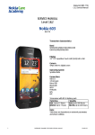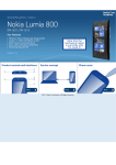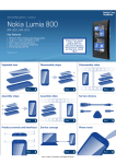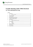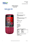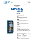
1
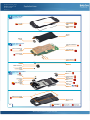
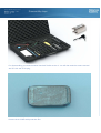
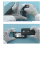
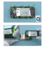
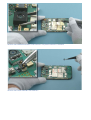
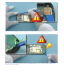
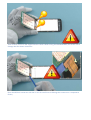
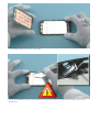
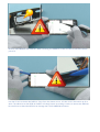
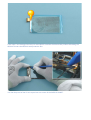
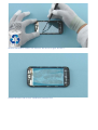
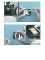
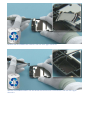
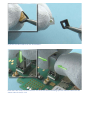
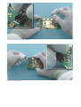
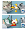
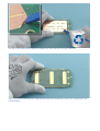
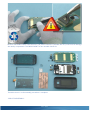
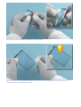
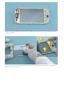
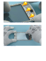
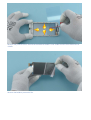
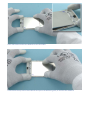
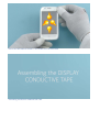
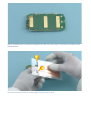
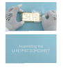
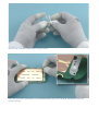
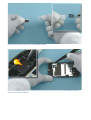
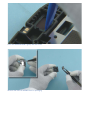
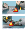
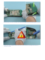
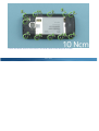
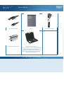
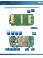
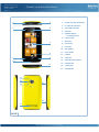
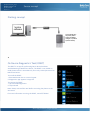
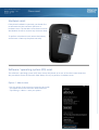
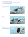
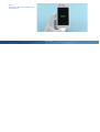
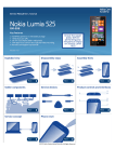
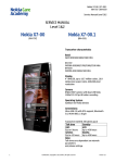
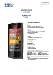
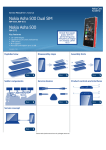
Service Manual for L1 and L2
Nokia Lumia 710
RM-803, RM-809
Key features
z
z
z
z
z
Windows Phone Mango operating system
Large 3.7" LCD TFT ClearBlack screen (not OLED)
Sync, store and share media files
Best instant social experience
Fast browsing with IE9
Version 1.0
Exploded view
Disassembly steps
More
Assembly hints
Disassembly video
More
Assembly hints video
More
Solder components
Service devices
More
Product controls and interfaces
More
More
More
Phone reset
More
©2011 Nokia | Confidential | All Rights Reserved.
More
Service concept
More
Service Manual Level 1 and 2
Exploded view
Nokia Lumia 710
RM-803, RM-809
Version 1.0
A-COVER ASSEMBLY
(I0001, I0002, I0004)
A-COVER
I0004
DISPLAY
I0005
EARPIECE
I0003
2
LIGHT SWAP PACKAGE
(I0006 - I0011)
UI KEYMAT DOMESHEET
I0007
DISPLAY CONDUCTIVE
TAPE
I0006
LIGHT SWAP PWB
I0008
DIPRO GASKET
I0010
SHIELD ADHESIVE
I0011
CAMERA
I0013
USB BOOT
I0012
CAMERA LENS BOOT
I0014
3
FLASH SUPPORT
I0025
MAIN CHASSIS ASSEMBLY
IHF SPEAKER
I0015
(I0015 - I0022)
LED FLASH
I0018
SPEAKER GASKET
I0016
FLASH BOOT
I0019
AV JACK
I0017
MAIN ANTENNA
I0021
MAIN CHASSIS
I0022
TYPE LABEL
I0009
CAMERA CROSS SCREW
I0023
BATTERY COVER
I0024
v1.0
Only available
as assembly
©2011 Nokia | Confidential | All Rights Reserved.
Not reuseable
after removal
Repair/swap
only in level 3
Service Manual Level 1 and 2
Nokia Lumia 710
RM-803, RM-809
Version 1.0
Disassembly steps
For disassembling you need the Nokia Standard Toolkit version 2. You will also need the camera removal
tool SS-278 and an AV plug.
Protect the A-COVER with protective film.
Use the opening notch on the left side of the device to release the BATTERY COVER.
Remove the BATTERY COVER.
Unscrew the eleven camera cross screws in the order shown. Do not use them again. Discard them.
Push the MAIN CHASSIS slightly forward and lift up the bottom end. Remove the MAIN CHASSIS.
Remove the CAMERA LENS BOOT with tweezers. Use plastic tweezers if available.
Remove the FLASH SUPPORT with tweezers.
Open the TOUCH WINDOW connector with the SS-93. Be careful not to damage the connector.
Use the SS-93 to lift up and push forward the ENGINE BOARD from the shown place. Be careful not to
damage the shown springs!
Then carefully turn over the engine board as shown. While turning the ENGINE BOARD, be careful not to
damage the two shown connectors.
Open the DISPLAY connector with the SS-93. Be careful not to damage the connector or components
nearby.
The ENGINE BOARD can now be separated.
Lift up the EARPIECE with the dental tool. Be careful not to injure yourself with the sharp end of the
dental tool.
Remove the EARPIECE with tweezers. When removing the EARPIECE, make sure not to touch the shown
part of it.
Use the SS-93 to release the DISPLAY. Start from the shown corner. Lift the corner and hold it up for a
while. The adhesive on the DISPLAY GASKET will slowly loosen up making it easier to remove the DISPLAY.
Be careful not to bend the DISPLAY or damage the TOUCH WINDOW connector.
Work around the DISPLAY with the SS-93 to release it completely.
Lift up and remove the DISPLAY. In case the shown tape is peeled off from the DISPLAY and remains on
the A-COVER, the driver on the DISPLAY may be damaged. In this case discard the DISPLAY.
If the tape is not damaged and stays on the DISPLAY continue the disassembly without discarding the
DISPLAY. Protect the DISPLAY with protective film.
Use the sharp end of the SS-93 to peel out one corner of the DISPLAY GASKET.
Remove the DISPLAY GASKET with tweezers. Do not use it again. Discard it.
Protect the other side of the A-COVER with protective film.
Remove the AV JACK with an AV plug.
Release the IHF SPEAKER with the dental tool.
Remove the IHF SPEAKER with tweezers. Do not use it again. Discard it.
Release the SPEAKER GASKET with the dental tool and remove it with tweezers. Do not use it again.
Discard it.
Push out the LED FLASH with the sharp end of the SS-93.
Remove the LED FLASH and the FLASH BOOT with tweezers.
Separate the LED FLASH from the FLASH BOOT.
Push down the camera removal tool SS-278 until the camera retaining clips are released. Hold from the
shown sides of the SS-278.
Then lift up and remove the CAMERA.
Remove the USB BOOT.
Remove the three shown SHIELD ADHESIVES with tweezers. Do not use them again. Discard them.
Use tweezers to remove the UI KEYMAT DOMESHEET. Be careful not to touch the MICROPHONE! Do not
use the UI KEYMAT DOMESHEET again. Discard it.
Use the SS-93 to peel off the DISPLAY CONDUCTIVE TAPE. Do not use it again. Disard it.
Make sure that the whole DISPLAY CONDUCTIVE TAPE and the adhesive remains are removed from the
ENGINE BOARD.
Remove the DIPRO GASKET with tweezers. Use plastic tweezers if possible. Be very careful not to damage
the nearby components. The DIPRO GASKET is not reusable. Discard it.
The Nokia Lumia 710 disassembly procedure is complete.
-END OF DISASSEMBLY-
©2011 Nokia
Service Manual Level 1 and 2
Nokia Lumia 710
RM-803, RM-809
Version 1.0
Assembly hints
For assembling you need the Nokia Standard Tool kit version 2.
Assembling the DISPLAY GASKET and the DISPLAY to the A-COVER.
Remove the two shown DISPLAY GASKET protective films.
Remove also the shown DISPLAY GASKET protective film from the other side. Do not remove the
protective film with the red pull out tape.
Before attaching the DISPLAY GASKET to the A-COVER check that there is no dust or adhesive residues
on the A-COVER.
Place the bottom end of the DISPLAY GASKET to the A-COVER. Make sure that all sides of the DISPLAY
GASKET are aligned correctly.
Do not place the DISPLAY GASKET on top of the shown A-COVER gasket.
Press the DISPLAY GASKET gently.
Remove the protective film. Check that the DISPLAY GASKET is not visible from the front side of the ACOVER.
Remove the DISPLAY protective film.
Place the bottom end of the DISPLAY to the A-COVER.
Lower down the top end of the DISPLAY and press the DISPLAY gently to activate the adhesive.
Check that the DISPLAY GASKET is not visible from the front side.
Assembling the DISPLAY CONDUCTIVE TAPE.
Before assembling the new DISPLAY CONDUCTIVE TAPE check that there is no adhesive residues on the
ENGINE BOARD.
Peel off the protective film as shown to get access to the cut outs.
Align the cut outs with the DISPLAY connector and the Proximity sensor.
Carefully press the DISPLAY CONDUCTIVE TAPE and slowly remove the protective film. Make sure not to
leave any air bubbles between the ENGINE BOARD and the DISPLAY CONDUCTIVE TAPE.
Remove the protective film and check the result.
Assembling the UI KEYMAT DOMESHEET.
Remove the UI KEYMAT DOMESHEET protective film.
Place the UI KEYMAT DOMESHEET to the ENGINE BOARD. Align the UI KEYMAT DOMESHEET with the
corner markings.
Press the UI KEYMAT DOMESHEET gently and check that it is aligned correctly.
Assembling the IHF SPEAKER and the SPEAKER GASKET.
Remove the protective films from the SPEAKER GASKET.
Place the SPEAKER GASKET to the MAIN CHASSIS. Make sure that the net side of the SPEAKER GASKET is
attached to the MAIN CHASSIS.
Press the SPEAKER GASKET gently with the SS-93.
Remove the new IHF SPEAKER from its packaging.
Place the IHF SPEAKER to the MAIN CHASSIS and check that the pins are aligned as shown. Press the IHF
SPEAKER with the SS-93 to activate the adhesive. Be careful not to touch the center part of the IHF
SPEAKER.
Assembling the ENGINE BOARD to the A-COVER ASSEMBLY.
Hold the ENGINE BOARD as shown and connect the DISPLAY CONNECTOR. Be careful not to bend the
DISPLAY CONNECTOR flex!
Lower down the bottom end of the ENGINE BOARD. While turning the ENGINE BOARD be careful not to
damage the TOUCH WINDOW connector!
Push the bottom end of the A-COVER to direction shown and gently push the ENGINE BOARD to its place.
Connect the TOUCH WINDOW connector with the SS-93. Be careful not to damage the connector or
components nearby!
Fasten the eleven camera cross screws in the order shown to the torque of 10 Ncm.
©2011 Nokia
Service Manual Level 1 and 2
Nokia Lumia 710
RM-803, RM-809
Version 1.0
Service devices
CA-101 Service cable
BP-3L
SS-278 Camera removal tool
Nokia Standard Toolkit (v2)
For more information, refer to the Service Bulletin
(SB-011) on Nokia Online. Supplier or
manufacturer contacts for tool re-order can be
found in “Recommended service equipment”
document on Nokia Online.
©2011 Nokia | Confidential | All Rights Reserved.
AC-10 Travel charger
Service Manual Level 1 and 2
Solder components
Nokia Lumia 710
RM-803, RM-809
Version 1.0
Home key
LED
V2401
Search key
LED
V2402
V2403
BOTTOM
Grounding
spring
Grounding
spring
Grounding
spring
Grounding
spring
X2702
X2701
X2704
X2703
X6201
v1.0
X6200
WLAN
Antenna springs
Back key
LED
RF Antenna
spring
X7403
S2558
S2559
S2553
X7410
Volume up
switch
Volume
down switch
Camera
switch
RF Antenna
spring
©2011 Nokia | Confidential | All Rights Reserved.
Service Manual Level 1 and 2
Product controls and interfaces
Nokia Lumia 710
RM-803, RM-809
Version 1.0
3
2
1
5
4
1 — Power key / Key lock button
2 — 3.5 mm AHJ connector
3 — Micro USB connector
4 — Earpiece
5 — Ambient light &
proximity sensors
6 — Touch screen
6
7 — Back key
8 — Search key
9 — Start key
10 — Microphone
9
8
7
11 — Strap holder
12 — Camera
13 — LED flash
14 — Secondary microphone
10
11
15 — Volume keys
16 — Camera key
17 — Loudspeaker
12
13
14
15
16
17
Ver. 1.0
©2011 Nokia | Confidential | All Rights Reserved.
Service Manual Level 1 and 2
Nokia Lumia 710
RM-803, RM-809
Version 1.0
Service concept
Flashing concept
Service
software
CA-101
Care Dummy Bat tery with power
supply via Nokia
charger or product
specific battery
Transceiver
On Device Diagnostics Tool (ODDT)
The ODDT is an app for performing basic device hardware
troubleshooting at Nokia Care Points. The ODDT is not visible on
retail phones and it is intended only for use by trained personnel at
Nokia Care Points.
To install the ODDT:
1. Enter ##634# on the on-screen keypad
2. Diagnostics app appears in Apps list
To remove the ODDT:
1. Tap and hold Diagnostics
2. Tap uninstall
Note: always uninstall the tool before returning the phone to the
consumer!
For more information on using the ODDT, see KICS TR2816.
©2011 Nokia | Confidential | All Rights Reserved.
Service Manual Level 1 and 2
Nokia Lumia 710
RM-803, RM-809
Version 1.0
Phone reset
Hardware reset
If the phone hardware is jammed, you should first
recommend that the consumer performs a
hardware reset. The hardware reset does not reset
the Windows Live ID or remove any consumer data.
To perform a hardware reset remove the battery
and reinsert it. Boot up the phone normally.
Software / operating system (OS) reset
The software / operating system (OS) reset returns the phone to its out-of-the-box state. Note that
this procedure erases all consumer data! Always first try to perform a hardware reset.
Option 1: About menu
- Use this option if the consumer knows the lock code
- This option warns the consumer about data loss!
- Tap Settings > About > reset your phone
Option 2: Hardware key combination
- Use this option if the phone is locked and the consumer does not know the code
- Note: no warning about data loss!
- Do not advertise this feature to consumers!
Follow next steps to perform OS reset with phone keys.
Step 1
Make sure the phone is turned
Off. Press and hold the Volume
down, Power and Camera keys
Step 2
When the phone vibrates release
the Power key
Step 3
Keep holding the Volume down
and Camera keys for another 5
seconds and then release the keys
Step 4
The phone will reset and boot up
automatically
©2011 Nokia
Service Manual Level 1 and 2
Nokia Lumia 710
RM-803, RM-809
Version 1.0
Version history
Version
Date
Description
1.0
04.11.2011
Approved
©2011 Nokia | Confidential | All Rights Reserved.