1
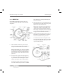
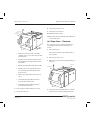
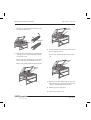
DotMate 6500/7500
Operator’s Manual
Esko-Graphics A/S
Copenhagen Division
Industriparken 35-37
DK-2750 Ballerup
Denmark
Tel.: (+45) 4473 6666
Fax.: (+45) 4473 6767
DotMate 6500/7500 Operator’s Manual
Doc. No.: 800325
DM 6500/7500 Operator’s Manual
Table of Contents
Contents
1. What You Can Find in the Manuals
5. Loading Media and Cassettes
1.1 What You Should Know Before Starting 1-3
5.1 Removing and Mounting the Input
Cassette. . . . . . . . . . . . . . . . . . . . 5-1
2. Product Description
2.1 Available Options. . . . . . . . . . . . . . 2-1
2.1.1 Registration Punch . . . . . . . . . . . . 2-1
2.1.2 Additional Input Cassettes . . . . . . . 2-1
2.1.3 Take-Up Cassette . . . . . . . . . . . . . 2-1
2.1.4 Water Saver Unit . . . . . . . . . . . . . 2-1
2.1.5 Chemistry Trolley Set. . . . . . . . . . . 2-1
2.1.6 RipMate Extensions. . . . . . . . . . . . 2-1
2.1.7 Laser Safety . . . . . . . . . . . . . . . . 2-2
2.1.8 Air Flow . . . . . . . . . . . . . . . . . . . 2-3
2.1.9 Status Panel . . . . . . . . . . . . . . . . 2-3
2.1.10 Function Switches. . . . . . . . . . . . 2-4
2.1.11 Media Path . . . . . . . . . . . . . . . . 2-5
2.1.12 Cabinet Parts . . . . . . . . . . . . . . . 2-6
2.1.13 Processor Description . . . . . . . . . 2-6
2.1.14 Identification of Processor Parts . . 2-6
3. Technical Assistance
3.1
3.2
3.3
3.4
Installation Requirements . . . . . . . . 3-1
Dimensions and Weight . . . . . . . . . . 3-1
Electrical Supply . . . . . . . . . . . . . . 3-1
Fuses . . . . . . . . . . . . . . . . . . . . . 3-1
4. Working With the DotMate
4.1. Overview. . . . . . . . . . . . . . . . . . . 4-1
4.2. Setting Up the Processor . . . . . . . . 4-1
4.2.1
4.2.2
4.2.3
4.2.4
4.2.5
Starting Up . . . . . . . . . . . . . . . . . 4-2
Setting the Processing Parameters . . 4-2
Antioxidation Function . . . . . . . . . 4-3
Other Processing Parameters . . . . . . 4-4
Filling the Processor . . . . . . . . . . . 4-4
5.1.1 Removing and Mounting the Optional
Take-Up Cassette . . . . . . . . . . . . . 5-3
5.1.2 Specifying Media and Cassettes in
RipManager . . . . . . . . . . . . . . . . 5-3
6. Producing a Test Job
6.1 Producing a Test Job . . . . . . . . . . . 6.1
7. Why Is Calibration Necessary?
7.1 Calibration on RipMate . . . . . . . . . . 7-1
7.1.1 Setting Up a Calibration (Film) . . . . 7-1
7.1.2 Know Your Film: Conventional vs.
Hard Dot. . . . . . . . . . . . . . . . . . . 7-1
7.1.3 Equipment . . . . . . . . . . . . . . . . . 7-2
7.2 Exposure Level and Calibration Set. . . 7-2
7.2.1 Calibration Troubleshooting . . . . . . 7-7
7.2.2 Maintaining Calibration Sets . . . . . . 7-7
8. Media Management
8.1 Defining the Media. . . . . . . . . . . . . 8-1
8.2 Defining an Input Cassette . . . . . . . 8-2
8.3 Backing Up and Retrieving Media and
Cassette Definitions . . . . . . . . . . . . 8-3
8.4 RipManager and Media Management. . 8-3
8.5 Customizing the Imagesetter and
Take-Up Parameters. . . . . . . . . . . . . 8-4
9. Optional Water Saver
9.1 Maintenance Overview . . . . . . . . . . 9-1
Page i
Table of Contents
10. Error Information
10.1
10.2
10.3
10.4
RipMate Main Window . . . . . . . . . 10-1
DotMonitor . . . . . . . . . . . . . . . . 10-1
Paper jams - Imagesetter . . . . . . . 10-1
Paper Jams - Processor . . . . . . . . 10-2
10.4.1 Media Does Not Load . . . . . . . . . 10-4
10.5 Problems Identified by Error
Messages . . . . . . . . . . . . . . . . . 10-4
10.5.1
10.5.2
10.5.3
10.5.4
10.5.5
Page ii
Error: Paper Jam . . . . . . . . . . . 10-5
Error: Out of Media . . . . . . . . . . 10-5
Error: Input Cassette Not Present . 10-5
Info: Media Low . . . . . . . . . . . . 10-5
Warning: Media Low. . . . . . . . . . 10-6
DM 6500/7500 Operator’s Manual
10.5.6 Error: Laser Failure . . . . . . . . . . 10-6
10.5.7 Error: Internal Communications
Failure . . . . . . . . . . . . . . . . . . 10-6
10.5.8 Error: Internal Power Failure . . . . 10-6
10.5.9 Error: Cover Open . . . . . . . . . . . 10-6
10.5.10 Error: Liquid Level Failure . . . . . 10-6
10.5.11 Error: Motor Failure . . . . . . . . . 10-6
10.5.12 Error: Invalid Clipping . . . . . . . 10-6
10.5.13 Error: Communications Failed . . . 10-6
10.6 Problems Not Identified by Error
Messages . . . . . . . . . . . . . . . . . 10-6
10.6.1 Media Has a Brown Color and
Density Is Too Low . . . . . . . . . . 10-6
10.6.2 Media Has a “Milky” Appearance. . 10-7
DM 6500/7500 Operator’s Manual
What You Should Know Before Starting
1. What You Can Find in the Manuals
This manual contains information about the installation, calibration, and daily use of the DotMate
6500/7500, including the handling of media and
cassettes, and concentrating mainly on the mechanical systems.
For information about the RipMate software RIP
and RipWatch, including a number of valuable tips
about how to get the most out of your RIP and
imagesetter, please see the separate RipMate Operator’s Manual.
For information on all aspects of maintenance of
the DotMate 6500/7500, please see the separate
DotMate 6500 and 7500 Easy Maintenance Guides,
respectively..
1.1 What You Should Know Be-
fore Starting
We recommend that you read the DotMate and
RipMate manuals before starting to work with the
DotMate/RipMate system. Please note in particular
that the installation of both the DotMate6500 and
RipMate should be carried out by an authorized
Esko-Graphics service engineer in order to ensure
proper installation of all system components.
This manual assumes that you have some familiarity with imagesetting as well as a basic working
knowledge of Microsoft Windows NT. If you are
in doubt about general operating procedures for
Windows NT, please consult the Windows NT
manuals supplied with your PC.
Page 1-3
DM 6500/7500 Operator’s Manual
Available Options
2. Product Description
The DotMate 6500/7500 is a fully integrated
imagesetter and processor that produces punched
and plate-ready film or press ready polyester
plates.
The imagesetter unit in the DotMate 6500/7500 is
a high-precision, internal drum imagesetter that interfaces to RipMate, a software RIP based on Harlequin ScriptWorks, but with additional features
added by Esko-Graphics.
The DotMate 6500/7500 processor is a 100% computer-controlled and -monitored unit. Developer
and fixer are filtered and recirculated, reducing the
consumption of chemicals and the cost of waste
disposal.
2.1 Available Options
The DotMate 6500/7500 has a range of options
that are available at the time of purchase and can
be easily incorporated any time afterwards. These
options are:
2.1.1 Registration Punch
There are various choices of registration punch
systems available for the DotMate. Please contact
Esko-Graphics for details of punch options.
2.1.2 Additional Input Cassettes
Additional cassettes are available to supplement
the supplied input cassette that is standard with the
DotMate 6500/7500.
Among the advantages of the DotMate 6500/7500
are:
2.1.3 Take-Up Cassette
• An extremely simple and efficient media path.
A take-up cassette is standard with DotMate 7500
and available as an option for DotMate 6500.
• A wide range of output resolutions (from 1200
to 3600 dpi) for flexibility in adapting to the
speed and quality demands of the individual job.
• An unusually wide range of spot sizes that are
automatically optimized to the chosen output
resolution.
2.1.4 Water Saver Unit
A water saver unit gives your DotMate 6500/7500 a
closed water system, thereby reducing the amount of
water used. Its built-in polypropylene and active carbon filters clean the water of impurities.
• The ability to image screen rulings up to 300 lpi
(118 lines per cm).
2.1.5 Chemistry Trolley Set
• A constant overpressure in the imagesetter unit
and a vacuum over the processor racks. ensures
that no chemical fumes from the processor can
flow back into the imagesetter.
A chemistry trolley set consisting of:
• Low noise level to fit into any working environment.
• User-friendly and service-friendly design.
• Trolley on wheels
• chemical containers.
2.1.6 RipMate Extensions
A number of optional modules are available to extend the RipMate software RIP. These include Har-
Page 2-1
Available Options
lequin Dispersed Screening and the RipMate InRIP
OPI Manager. For additional RipMate extensions,
see RipMate documentation.
2.1.7 Laser Safety
The DotMate 6500/7500 is a Class I laser product
and contains a laser, which is totally shielded by
the cabinet. When the cabinet of the imagesetter
unit is opened, the interlock system automatically
switches off the laser, thus eliminating the risk of
laser radiation.
WARNING: Only authorized service personnel
may override the interlock system. The warning labels inside the cabinet of the DotMate and on the
drum assembly are intended for such personnel.
DANGER - LASER RADIATION
WHEN OPEN AND INTERLOCKS
DEFEATED. AVOID EXPOSURE TO
BEAM
ATTENTION - RAYONNEMENT
LASER DANGEREUX EN CAS D’OU
VERTURE ET LORSQUE LA SECURITÉ
EST NEUTRALISÉE. EXPOSITION
DANGEREUSE A FAISCEAU
ACHTUNG - WARNUNG VOR LASERSTRAHLEN
BEI OFFENEM GEHÄUSE UND
AUSSCHALTETEM SICHERHEITSSCHALTER.
DIREKTE BESTRAHLUNG
VERMEIDEN
ADVARSEL - LASERSTRÅLING
NÅR ÅBEN OG SIKKERHEDSAFBRYDERE
BLOKERET. UNDGÅ DIREKTE
BESTRÅLING
Page 2-2
DM 6500/7500 Operator’s Manual
DM 6500/7500 Operator’s Manual
Available Options
2.1.8 Air Flow
2.1.9 Status Panel
The DotMate 6500/7500 has an air intake on the
rear panel of the imagesetter unit and a fan in the
left-hand side of the imagesetter.
The diagram below shows the status lights on the
DotMate 6500/7500 status panel.
Cooling air is drawn in through the rear intake and
circulated around the interior of the cabinet.
On the upper rear section of the left side panel of
the processor is an air outlet fan and vent. The intake fan creates a pressure within the imagesetter
part of the DotMate, while the outlet fan creates a
vacuum in the processor. This creates an airflow
through the machine.
A pre-filter and carbon filter in the imagesetter air
intake ensures particle-free air to the imagesetter,
while similar filters in the processor outlet ensure
that fumes from the processor are neutralised before being released.
ON, ONLINE, BUSY, ERROR and TAKE-UP are messages that relate to the operational status of the
DotMate.
The airflow has several purposes:
• it ensures that any heat produced by the
imagesetter electronics is extracted.
• it ensures that no fumes from the processor can
enter the imagesetter section.
• it ensures that the temperature in the imagesetter
and processor remains stable.
• ON is displayed whenever main power is on.
• ONLINE is displayed whenever the DotMate
6500/7500 is ready to produce jobs from
RipMate and RipManager. It goes off-line when
you enter DotMonitor and go into the main menu.
• BUSY is displayed whenever the DotMate
6500/7500 is working, i.e., during imagesetting
or media transport.
• ERROR is displayed if an error occurs in the
functioning of the DotMate. More info is listed
in the RipMate Window and in the processor
service status window, and more detailed information is displayed in the DotMonitor.
• TAKE-UP will blink to show that the media has
been cut and the optional take-up cassette can be
removed. It will be lit continuously when the
optional take-up cassette is present.
Page 2-3
Available Options
2.1.10 Function Switches
LOAD, EJECT, and UNLOAD are messages that
relate to the status of the media in the drum. Only
one of these messages is displayed at any one time
and only when the function can be selected.
Pushing the function switch carries out the function
displayed:
• The LOAD light will illuminate when the
DotMate 6500/7500 is ready for new media to
be loaded into the drum. Pushing the function
switch transports the media into the drum for exposure. The LOAD light will blink if the input
cassette runs out of media.
• The UNLOAD light will illuminate when the
DotMate 6500/7500 is ready to un-load media.
Pushing the function switch at this point will
cause the media in the drum to be retracted into
the input cassette, after which the input cassette
can be removed and a different one inserted.
Note: Remember to change cassette in RipManager/MediaManager when you change to another
cassette.
• EJECT is available when the drum and/or the
optional take-up cassette contains exposed media. If you click on EJECT, the media will be cut
and fed to the online processor or take-up cassette, depending on job selection. On DotMate
6500/ 7500 CTP EJECT will output the last exposed plate.
STANDBY is a message that is displayed to indi-
cate that the DotMate 6500/7500 can be set to a
standby setting.
This setting should be used when the processor is
not in use (overnight or for long periods during the
working day). Its functions are:
Page 2-4
DM 6500/7500 Operator’s Manual
• to save power.
• to reduce chemistry loss by oxidation (because
the temperature in the chemistry is lowered).
• to prevent crystallization of the developer/activator and fixer/stabilizer in the system. (The
processor media transport rollers run periodically).
Pressing the standby switch puts the DotMate
6500/7500 in the standby mode. The light will then
begin to blink to show that the processor is now in
the standby mode.
When in standby, a job from the RIP will interrupt
the setting. When standby is required again, select
STANDBY once more.
It can take up to 30 minutes for the chemistry to
reach its correct temperature when the DotMate
6500/7500 is taken out of standby mode, depending how long standby mode has been running and
the standby mode settings.
DM 6500/7500 Operator’s Manual
2.1.11 Media Path
The DotMate 6500/7500 imagesetter unit has a
very short, efficient media path, shown schematically below.
Available Options
if the media is not properly loaded and positioned for exposure.
3. The optics unit moves to the right-hand end of
the drum and exposes the media, starting at the
right and moving towards the left.
The media is exposed by a laser which spins
continuously around a central spindle as the
carriage moves along the length of the drum.
The carriage will only move as far as necessary
to expose the job, depending on the format of
the page and its orientation in the drum.
4. The input and output rollers and the rollers on
the front conveyor then transfer the exposed
media from the drum into the processor.
At the same time, media for exposure of the
next page enters the drum. The exposed media
is cut and fed through the front and rear conveyors into the processor.
1. When a LOAD command is given, the input
rollers on the input module pull the media from
the input cassette and load it into the drum.
During media loading, the carriage upon which
the optics unit is mounted, moves the guides on
the left and right of the imagesetting drum in to
support the film so that it does not fall onto the
optics unit.
2. The input rollers together with the output roll-
ers on the output module, feed the media all the
way around the drum and through the output
module, and hold the media securely in place.
The input and output sensors monitor the position of the media and report an error to the RIP
Page 2-5
Available Options
DM 6500/7500 Operator’s Manual
5. When an EJECT command is given, the knife
in the output module cuts the media and the
front conveyor rollers pass the media through
the front conveyor into the rear conveyor and
into the processor.
In a DotMate 7500SA, or if the take-up cassette
is fitted, on selection, the media will pass
through the front conveyor and into the take-up
cassette. with no cut between the exposed jobs.
The cut is made when an EJECT command is
given.
Function
switches and
status panel
Top cover
Back panel
Front shield
Front shield
release catch
(under the hand
grips on
each side)
Right hand door
Left-hand door
Main switch
Front panel
Front cover
Front cover
release catches
(each side)
2.1.12 Cabinet Parts
The drawing below shows the main external cabinet parts, release catches and switches of the
DotMate 6500/7500.
Processor
cover
Processor
back panel
Left-hand door
Function switches and
staus panel.
Front shield
Conveyor
cover
(underneath
the processor
cover)
Front cover
2.1.13 Processor Description
The processor unit of the DotMate 6500/7500 is a
high quality rapid access processor. Development
time, temperature, and replenisher volumes can be
adjusted to meet the specifications for most types
of rapid access film and polyester plate.
A Water Saver Unit is available as an option. It
provides closed-circuit recycling of water, considerably reducing the water consumption. A description of this unit can be found in Chapter 9 • Water
Saver Unit.
Right-hand side panel
Main power switch
Right-hand door
Foot panel
Front cover
release catches
(each side)
Page 2-6
2.1.14 Identification of Processor Parts
DM 6500/7500 Operator’s Manual
Available Options
Storage for overflow drain
tool and filter bowl wrench
Fixer/stabilizer
filter
Developer/activator
filter
Thin blue Fixer/stabilizer
supply hose
Thick blue Fixer/stabilizer
waste hose
Thin red Developer/activator
supply hose
Thick red Developer/activator
waste hose
Page 2-7
DM 6500/7500 Operator’s Manual
Installation Requirements
3. Technical Assistance
In order to ensure that the entire DotMate/RipMate
system is properly installed and configured, the
DotMate 6500/7500 must be installed by an authorized Esko-Graphics service engineer in accordance with the installation instructions in the
DotMate 6500/7500 Service Manual and with national and local regulations concerning electrical
safety and plumbing.
3.1 Installation Requirements
Net weight:
• DM 6500/7500
450 kg (992 lbs)
DM7500SA
250 kg (551 lbs)
Gross weight:
• DM 6500/7500
500 kg (1102 lbs)
DM7500SA
300 kg (661 lbs)
The DotMate 6500/7500 must be placed on a hard,
flat, stable surface with the following space requirements:
3.3 Electrical Supply
• free space of approximately 70 cm (28") at the
sides to allow for opening the imagesetter side
doors, removing the optional chemistry tray of
the processor and for maintenance operations.
The DotMate 6500/7500 must be connected to a
grounded 200-240 VAC, 50 or 60 Hz wall outlet as
shown in the Installation Instructions which are
packed with the machine.
• a height of 220 cm (87") to allow for opening
the processor cover.
WARNING: The DotMate 6500/7500 is Class I
• free space of approximately 50 cm (20") at the
front for inserting and removing the cassettes.
3.2 Dimensions and Weight
Machine dimensions:
• DM 6500
width 123 cm, height 115 cm, depth 160 cm
(width 48", height 45", depth 63")
DM 7500
electrical equipment. For your personal safety, it
must be connected to a protective ground (earth) in
accordance with national and local regulations.
3.4 Fuses
The DotMate 6500/7500 is provided with a fuse in
the phase only, not in the neutral. If the machine is
connected to a power supply that uses phase-tophase connection, to achieve a voltage within the
specified range, make sure the connection is done
in accordance with national and local regulations.
width 145 cm, height 115 cm, depth 160cm
(width 58", height 45", depth 63")
Shipping dimensions:
• width 134 cm, height 134 cm, depth 177 cm
(width 53", height 53", depth 70")
Page 3-1
DM 6500/7500 Operator’s Manual
Overview
4. Working With the DotMate
Important : Before carrying out the activities below, make sure that the DotMate 6500/7500 and
RipMate software have been properly installed by
an authorized Esko-Graphics service engineer according to the instructions in the DotMate
6500/7500 Service Manual and RipMate Operator’s Manual.
• all three racks are in place and the overflow
pipes are properly mounted.
• Windows NT has been started on the RIP
PC.
2. Check that all the necessary cables (power,
SCSI and RS-232) are properly connected.
We also recommend that an authorized EskoGraphics service engineer be available to give assistance while the activities in this section are carried out.
The cables should be connected by an authorized Esko-Graphics service engineer. Otherwise the guarantee will be invalidated.
4.1. Overview
CAUTION: Never connect or disconnect a
This chapter takes you quickly through the operations that are necessary in order to get your first
output from the DotMate 6500/7500:
• Starting up the system.
• Setting the processing parameters.
• Filling the processor with chemistry.
• Loading media into the DotMate.
• Specifying media and cassettes in RipMate.
• Outputting a test job.
More information about the various functions of
the DotMate 6500/7500 and RipMate are found in
this manual and in the RipMate Operator’s Manual.
4.2. Setting Up the Processor
1. Before starting, make sure that:
• the processor is properly installed.
• the processor is clean.
SCSI cable to any unit while the power is on.
3. With reference to your film and the vendor’s
specifications, mix your developer/activator
and fixer/stabilizer.
You are now ready to connect the containers
for the chemistry.
WARNING: For your personal safety, use
gloves and safety glasses when mixing chemicals.
4. Remove the right-hand side panel, if not al-
ready removed, by simply lifting up and away.
The figure below shows the main parts in the
chemical compartment.
5. Pull out the optional trolley (if fitted) approxi-
mately 70 cm (28").
6. Place the containers for developer/activator
and fixer/stabilizer onto the trolley and position
the trolley in the processor compartment.
Page 4-1
Setting Up the Processor
7. The supply hoses are the thin PVC hoses. Place
the red supply hose in the developer/activator
container and the blue supply hose in the
fixer/stabilizer container, so that the hoses
reach the bottom of the containers.
DM 6500/7500 Operator’s Manual
4.2.1 Starting Up
1. Switch on the power.
The power switch is located on the left-hand
side of the foot panel.
8. The used chemistry waste hoses are the thick
PVC hoses. Place the red used developer/activator hose in the empty developer waste container and the blue used fixer/stabilizer hose in
the empty fixer waste container.
9. Place the two waste containers in front of the
chemistry trolley as shown
10. Ensure that the service engineer has properly
connected the water inlet and outlet hoses.
11. Mount the right-hand side panel.
Position the panel so that the brackets on the
bottom of the panel engage in the studs on the
side of the processor and the top of the panel
fits over the lip on the top of the processor.
Then drop it into place.
Page 4-2
2. Switch on the RIP PC and start up the
RipManager and RipMate, in that order.
RipManager must always be started up first.
4.2.2 Setting the Processing Parameters
Proceed as follows to set the processing parameters:
Developer/activator, fixer/stabilizer temperatures &
antioxidation values
1. In RipManager, double-click on DotMate
6500/7500 and then Preferences.
The Device Preferences window appears.
DM 6500/7500 Operator’s Manual
Setting Up the Processor
The values shown in the right-hand row
(Standby), are selected values for the same parameters, but apply when the DotMate
6500/7500 is in the standby mode.
3. To change the values, double-click in the rele-
vant text box and type in the desired value
within the ranges specified below:
• Dev/Act temperature: 15 - 45EC.
• Fix/Stab temperature: 15 - 45EC.
...for film
• AntiOx interval:
5 - 60 minutes.
• AntiOx Dev/
Act replenish:
0 - 300 ml.
• AntiOx Fix/
Stab replenish:
0 - 300 ml.
NOTE: An explanation of the antioxidation
function is given below.
4. Click on OK to confirm the new values.
5. Close the Device Preferences window.
...for polyester plate
4.2.3 Antioxidation Function
rack that is relevant to the configuration of the
DotMate 6500/7500.
When developer/activator is exposed to the air, it
oxidizes, which reduces its effectiveness. The
antioxidation function replenishes the developer/activator at the desired intervals to compensate for oxidation.
The values shown in the left-hand row (Processing or idle), are selected values for Developer/Activator Temperature, Fixer/Stabilizer
Temperature and Antioxidation Amount.
The amount of antioxidation replenishment required is typically between 10 and 25 liters a week;
the exact figures will be found in the chemistry
manufacturers specification sheets.
2. Select Rack type and choose the appropriate
Page 4-3
Setting Up the Processor
The default value of 0 for AntiOx Dev/Act replenish
and AntiOx Fix/Stab replenish means that the function is not activated.
DM 6500/7500 Operator’s Manual
For Media name, type in whatever name you like.
However, the AntiOx-interval should be set to 10
minutes. This causes a five-second rotation of the
rollers in the processor every ten minutes which
maintains the rollers and chemistry.
• The necessary values for Developer/Activator Time, Developer/Activator Replenishment, Fixer/Stabilizer Replenishment, and
Dryer Temperature, will be found in the
manufacturer’s specification sheets for the
developer/activator and fixer/stabilizer.
4.2.4 Other Processing Parameters
NOTE 1: Developer/Activator Time must be set
The remaining processing parameters are specified
via the Media List window which is accessed from
the DotMate menu in RipManager. Up to 10 media
can be programmed and stored.
1. In RipManager, select Shut down (if not al-
ready shut down).
2. Select Media Management in the DotMate
pull-down menu.
3. In the Media Management window, click on
Edit Cassette.
The following window appears:
according to the manufacturer’s specifications
when calibration is performed. If the Developer/Activator Time is changed, a new calibration test must be performed for that media.
NOTE 2: For film, developer and fixer replenishment is based on the area (square meters) of
media processed and the degree of exposure.
The replenishment values that should be entered are for the 50% exposed area shown on
the specification sheet.
NOTE 3: For polyester plate, the replenishment
values are based on the area of the plate only
and not just the exposed area, as it is for film.
5. When all the desired values have been entered,
click on OK (3 times).
4.2.5 Filling the Processor
Fill the processor as follows :
1. Lift up the top cover of the processor.
2. Remove the black anti-condensation cover
over the chemistry tanks.
4. To change the values, double-click in the rele-
vant text box and type in the desired value.
Page 4-4
3. In the RIP PC’s Program Manager window,
double-click on the Processor Service Program
in the RipMate group window.
DM 6500/7500 Operator’s Manual
Setting Up the Processor
4. Click on Tools and then Main Control Panel.
The following window will appear.
5. Activate the Active/on button in the processor
section.
The following window appears:
CAUTION: Proceeding with the following
steps without chemistry in the relevant containers can damage the pumps.
6. Activate the Developer/Activator check box in
the Refill section.
The developer/activator tank will begin to fill
up. After 40 seconds (safety timer), the pump
will stop. If OK, press the button again.
The pump stops when the required level is
reached or after 5 minutes running.
Note: This applies to all tanks.
7. Repeat step 6 but activating/deactivating the
Fixer/stabilizer check box.
8. Repeat step 6 but activating/deactivating the
Water check box.
NOTE: This step is not necessary if your
DotMate has the water saver unit fitted.
9. When all three tanks have been filled, close the
window.
10. Replace the black PVC anti-condensation
cover and lower the top cover of the processor.
Page 4-5
Setting Up the Processor
The processor starts heating the chemistry to
the preset temperature level. The values used
are the preset values in RipManager Preferences menu.
Page 4-6
DM 6500/7500 Operator’s Manual
DM 6500/7500 Operator’s Manual
Removing and Mounting the Input Cassette
5. Loading Media and Cassettes
The DotMate 6500/7500 uses daylight loading film
with the emulsion side out. Follow the instructions
below to ensure that the film is properly loaded.
The input and optional take-up cassettes are both
accessed conveniently from the front of the
DotMate. The upper bay is for the input cassette
and the lower bay for the optional take-up cassette.
5.1 Removing and Mounting the
Input Cassette
1. Lower the shield.
4. Lift the spindle out of the cassette.
5. Remove the left-hand retainer by unscrewing it
completely (the locking device on the inside of
the retainer will no longer grip the spindle).
The retainer can then be pulled off the spindle.
2. Slide the input cassette out of its compartment
using the two hand grips on the sides.
6. Slide the media onto the spindle, making sure
it fits snugly against the right-hand retainer.
Be sure to place the media roll as shown below,
i.e., with the emulsion side facing down.
3. Place the cassette on a table and open it by re-
7. Slide the left-hand retainer back onto the spin-
leasing the locks on each side in the direction
shown.
dle until the locking device on the retainer can
be felt to engage in the slot on the spindle.
Page 5-1
Removing and Mounting the Input Cassette
Approximately 3 mm before the end cap.
8. Screw the left-hand retainer approximately 3
1/2 - 3 3/4 turns, until it is locked onto the spindle.
DM 6500/7500 Operator’s Manual
11. Close the lid of the cassette and lock it by mov-
ing the locks on each side in the direction
shown.
Ensure that the media is not pinched between
the cassette lid and body.
It is important that the retainer be neither too
tight nor too loose. The retainer is correctly
locked when the media roll fits tightly against
the right-hand retainer.
12. Slowly pull out the protective wrapper/leader
until about 2.5 cm (1") of media is exposed.
9. Place the spindle with the media in the cassette,
ensuring that the two notches on the spindle fit
into the corresponding slots of the cassette.
13. Carefully peel off the entire protective wrap-
per/leader or, if necessary, cut it off with scissors.
Some types of media have a small sticky area
(daylight loading residue) left across the width
of the media when the protective wrapper is removed. This should also be cut off.
14. Tighten the media roll in the cassette by turn-
ing the gear on the side of the cassette clockwise until the edge of the media is flush with
the lip of the cassette.
10. Carefully remove the fastening tape from the
media and pull out enough media so that it extends past the lip of the cassette.
Page 5-2
The cassette is now ready for loading into the
DotMate.
DM 6500/7500 Operator’s Manual
Removing and Mounting the Input Cassette
2. Slide the take-up cassette out of its compart-
ment using the two hand grips on the sides.
3. To remount the cassette in the DotMate, hold
the cassette by the hand grips on each end,
place it in the bottom compartment of the
Dotmate, and push it in until the spring locks
engage.
15. To mount the cassette in the DotMate, hold the
cassette by the hand grips on each end, place it
in the top compartment of the Dotmate, and
push it in until the spring locks engage.
The cassette is naturally balanced at the correct
angle when held by the two end grips.
The cassette is correctly mounted when two
white spots can be seen on the rail under the
cassette.
The cassette is naturally balanced at the correct angle when held by the two end grips.
If media has been exposed, remember to use the
EJECT command before attempting to remove the
take-up cassette.
EJECT can be chosen when the EJECT lamp is illuminated. The TAKE-UP cassette lamp must blink
before the take-up cassette can be removed.
5.1.2 Specifying Media and Cassettes
in RipManager
5.1.1 Removing and Mounting the Op-
tional Take-Up Cassette
To remove the cassette:
1. Raise the shield.
The RipManager program module provides facilities for specifying up to 16 different input cassettes, including the type of media they contain, the
length of the media roll at the time of loading, and
how soon you want to receive a notice via the RIP
that the media is running low. It also lets you
change the maximum amount of film to the optional take-up cassette (up to the default setting of
15 m/50 ft) and adjust the amount of extra media
fed into the take-up cassette when you perform an
Eject. If you would like to use these facilities, see
the instructions in Chapter 8 • Media Management.
You can, however, produce output on the DotMate
6500/7500 without them.
Page 5-3
DM 6500/7500 Operator’s Manual
Producing a Test Job
6. Test Job
The very first job you send to the DotMate
6500/7500 is used to calculate the maximum data
rate between it and the RIPPC. Although you could
simply choose Print Uncalibrated Job from the
RipMate menu, you might not achieve the best data
rate. Instead, we recommend exposing a test job,
called lines.ps, that was installed on your RIPPC as
part of the RipMate software installation process.
6.1 Producing a Test Job
1. In the RipMate window, choose Page Setup
Manager from the RipMate pulldown menu.
The Page Setup Manager window appears.
3. From the Output device menu, choose
DotMate 6500/7500.
4. In the Resolution drop-down box, choose
2540.
2. From Page Setup Manager, select New.
The New Page Setup window appears.
To achieve the best possible data rate, the resolution should be set to 2540.
5. Double click on Configure device... to open
the Configure Device window.
Selection of the on-line processor or the
take-up cassette configuration determines
which of those two the job is sent to.
Page 6-1
Producing a Test Job
DM 6500/7500 Operator’s Manual
- DM 6500: max. width 530 x 505 with polyester.
For the time being, use 0 for the other parameters in this window. See the chapter on Page
Setup in the RipMate Operator’s Manual for
information about how to set the various parameters.
9. Click on OK and the New Page Setup window
re-appears.
6. Select the values as required by refering to the
RipMate Operator’s Manual and select OK.
7. In the Page Setup window, select Page Lay-
out.
The Page Layout window (shown on the facing
page) appears.
10. Select separation style Monochrome.
11. Select Cassette and choose one of the cassettes
that matches the media being used.
8. For Page width and Page height, type in the
values as shown:
- DM 7500: max. width 750 x 610 mm.
- DM 6500: max. width 650 x 480 with film
Page 6-2
12. Select Save As.
The Save Setup window appears.
DM 6500/7500 Operator’s Manual
Producing a Test Job
18. Click on OK to start exposing the job.
Once you have ensured that the system is up and
running, you will want to start exposing real jobs.
Before doing this, calibrate the imagesetter as explained in Chapter 7 • Calibration.
13. In the Save Setup window, type in test2540
and then click on Save.
14. In the Page Setup Manager window that ap-
pears, click on OK.
15. From the RipMate menu, choose Print File...
16. Choose the file lines.ps, which is located in
<your RipMate directory name>\PS\.
The Print File window appears.
17. Select Page Setup and choose test2540.
Page 6-3
DM 6500/7500 Operator’s Manual
Calibration on RipMate
7. Why Is Calibration Necessary?
In order to compensate for dot gain and produce
consistent output, an imagesetter must be calibrated for linearity. An imagesetter is “linear”
when every tone specified in the input gives that
same tone in the output, so that the curve comparing input and output is a straight line:
tions of an output resolution, screen frequency
range, dot shape, exposure level and negative or
positive output. In fact, each Page Setup must be
associated with a specific calibration (see the
RipMate Operator’s Manual for a full explanation
of the Page Setup concept).
Calibrations are created and stored using the Calibration Manager function in the Output menu of
RipMate.
7.1.1 Setting Up a Calibration (Film)
For film, you need to find an exposure level which
ensures that the 100% exposed areas of the film
have a density as recommended by the film manufacturer.
The optimum density for each brand and type of
media is specified by its manufacturer. The value
may vary quite a bit, depending on the media type,
and since output resolution, screen frequency and
dot shape also have an influence on the optimum
exposure level, you should never create a calibration set without first adjusting the exposure level.
In four-color work, even small deviations from a
linear curve can cause significant errors in the colors produced—for example, changes in color balance and contrast, loss of brightness, and loss of
highlight or shadow detail. Even if the imagesetter
is very accurate, the output will still be affected by
the type and brand of media used, so its calibration
should be regularly checked.
7.1 Calibration on RipMate
RipMate lets you create and store calibrations for
different types of media and for various combina-
After adjusting the exposure level, the individual
dot percentages are calibrated. This is a semi-automatic process performed by RipMate, based on
your measurements of tint values in a special test
job.
7.1.2 Know Your Film: Conventional vs.
Hard Dot
Conventional rapid access films typically have an
optimum density of 3.8 - 4.2, which is the initial
density level you will be looking for. When density
Page 7-1
Exposure Level and Calibration Set
DM 6500/7500 Operator’s Manual
is correct, you will then look at the accuracy of the
dot percentages.
optimum exposure level lies, and then close in on a
more accurate value.
In contrast, hard dot films can have maximum densities of anywhere from 4.8 - 6.0, which may be
impossible for some densitometers to register.
Therefore, when calibrating for this type of film, a
different strategy is employed.
NOTE: In order to carry out an exposure sweep,
you must know the output resolution for which
the calibration will be used. A calibration is only
valid for one output resolution.
In order to get good results from your imagesetter,
it is important to understand the characteristics of
the media you are working with. Therefore, before
starting to use a particular type of media, it is a
good idea to consult with your media supplier.
7.1.3 Equipment
For film calibration, you will need a reliable and
accurate densitometer that can measure transmission and that can read out the results both as density and as dot percents. If you intend to use hard
dot film, it is recommended that the densitometer
should be capable of measuring the high densities
that such films can produce.
7.2 Exposure Level and Calibra-
tion Set
When you have found the exposure level for a
given media and output resolution, you can create
a calibration set. This procedure you will typically
use in your daily work to create and check calibrations.
You will need a separate calibration for each combination of media, output resolution, dot shape, exposure level, range of screen frequencies, and
negative or positive output that you intend to use.
In the procedure below, find the exposure level as
follows:
1. In the RipMate window, choose Page Setup
Manager from the RipMate pulldown menu.
The Page Setup Manager window appears.
Exposure level is determined by producing an exposure sweep, which is the automatic exposure of
uncalibrated test strips at a series of different exposure levels. The density of each strip is then measured to find out which exposure level comes
closest to the media manufacturer’s optimum density specification.
This step is normally only necessary when you are
starting to work with a new media type or a new
resolution. By manipulating the starting value, end
value and step value of the exposure sweep, you
can start by getting a rough estimate of where the
Page 7-2
2. From Page Setup Manager select New.
DM 6500/7500 Operator’s Manual
Exposure Level and Calibration Set
5. Set the desired screen frequency, spot shape
and angle and click on OK to return to New
Page Setup.
6. Select the desired cassette from New Page
Setup.
7. Click on Save As to close the New Page Setup
window.
The Save Setup window reappears.
8. Save as, for example test2540 and then click
on Save.
The Setup Manager window reappears.
9. Click on OK.
NOTE: When naming a Page Setup, use only let-
The New Page Setup window appears.
ters and numbers. Otherwise an error may occur.
3. In the Resolution box at the top of the window,
10. Select Start Exposure Sweep Mode from the
choose an output resolution.
4. Click on the Style icon to open the Style dialog.
Select edit Monochrome style set.
DotMate 6500/7500 pulldown menu. Select
device to DM6500/7500, if Preview is shown.
This function allows for a considerable saving
of film while calibrating your DotMate
6500/7500 by exposing all calibration sweeps
on one film (while there is room on that film).
11. Select Print Calibration from the Output
pulldown menu.
Page 7-3
Exposure Level and Calibration Set
DM 6500/7500 Operator’s Manual
17. When the job has been set and processed, mea-
sure the exposure density of each test strip:
• Conventional media : measure the density in
the D Max field. For film, it should be between 3.8 and 4.2.
• Hard dot film : please contact your supplier
for details.
• Polyester plate : please contact your supplier
for details.
12. Select, for example, test2540.
13. Type in the desired starting value for the expo-
sure sweep in the From field in the Print Calibration dialogue, and press the Tab key.
The exposure can be from 1 to 1200.
14. Type in the desired end value for the exposure
sweep in the To field in the Print Calibration
dialogue, and press the Tab key.
15. Type in the desired interval between exposure
values in the Step field in the Print Calibration
dialogue, and press the Tab key.
Use a relatively large step value the first time
around if you are not sure where the optimum
exposure value lies. Once you know approximately where to look, you can repeat the exposure sweep with a revised starting value
(From), end value (To) and a smaller step value
(Step).
16. Click on Print Exposure Sweep to generate the
exposure sweep.
The RIP will now generate all the uncalibrated
test strips in the sweep.
Page 7-4
DM 6500/7500 Operator’s Manual
Exposure Level and Calibration Set
20. In the Exposure box, type in the exposure
value you determined in step 18, from the test
strip with the correct density/exposure.
21. Click on the OK button twice.
18. If the measured value is not within the toler-
ance listed in step 17, repeat steps 11 to 18.
• From the test strips, find the exposure value
that comes closest to the exposure density in
step 17.
When the correct exposure setting has been
achieved, you are now ready to calibrate the
dot percentages, using the test strip with the
correct exposure.
22. Using a densitometer, measure the dot percent-
• Change the From, To and Step in the Print
Calibration window as necessary in order to
narrow in the exposure value.
ages for each tint square - from “0.0” to
“100.0” - in the test job. Write the measured
value in the box below each square.
19. When the exposure value is within the speci-
fied tolerance, open the Page Setup Manager
window from the RipMate menu, select
test2540 and then click on the Edit button.
The Edit Page Setup “test2540” window appears.
23. From the Output menu in RipMate, choose
Calibration Manager.
The Calibration [Dot Gain] Manager window
appears.
24. Click on New.
Page 7-5
Exposure Level and Calibration Set
• If you are revising an existing calibration
set, doubleclick on its name in the list instead of New.
The Edit Uncalibrated Target for DotMate
6500/7500 window appears. Note that the Resolution, Dot shape, and Exposure are taken from the
last edited Page Setup. The Screen freq boxes will
display a range that includes the frequency you
specified.
For more information about Edit Uncalibrated Target for DotMate 6500/7500, refer to the RipMate
Operator’s Manual.
DM 6500/7500 Operator’s Manual
As you enter the values, the graph will give
you a visual idea of the media and
imagesetter’s deviation from a linear curve.
27. When all the values have been entered, click
on the OK button.
The Calibration [Dot Gain] Manager window
reappears.
28. Click on OK.
The new calibration set will be saved.
29. Before clicking on OK, you can choose to cre-
ate or edit additional calibration sets.
NOTE : If you click on the Cancel button in the
Calibration [Dot Gain] Manager window, all the
changes you have made to calibration sets since
opening the window will be lost.
30. Open the Page Setup Manager window in the
RipMate menu and double click on test2540.
31. In the Calibration pulldown menu, choose the
calibration you just created and click on the OK
button and then OK in the Page Setup Manager.
25. In the Name field, enter a suitable name, if the
calibration set is a new one, e.g. CalTest2540.
26. Using the tab key to move from field to field,
enter the measured value for each tint square
into the box below the corresponding tint percent.
• Enter the values as measured. You do not
have to make any calculations between the
expected values and measured values.
Page 7-6
32. From the Output menu in RipMate, choose
Print Calibration, click on test2540 and then
click on Print Calibrated Target.
The test job will be exposed, using the new calibration.
33. When the test job has been set and processed,
check its density and dot percentages. If the
measured values are not within +/– 1 of the expected values, continue with the steps on the
following page.
DM 6500/7500 Operator’s Manual
34. From the Output menu in RipMate, choose
Print Calibration, click on test2540 and then
click on Print Uncalibrated Job. Repeat steps
22-32.
35. If the revised values are still not within +/– 1 of
the expected values, please refer to Calibration
troubleshooting below.
36. Select Stop Exposure Sweep Mode from the
DotMate 6500/7500 pulldown menu.
The Stop Exposure Sweep Mode window,
shown on the following page, will appear.
Exposure Level and Calibration Set
processor are maintained; the storage temperature and length of storage of the media;
and whether the processor is used for developing other materials.
• Make sure that your DotMate 6500/7500 is
in good working order. If necessary, have an
authorized Esko-Graphics service engineer
check the machine.
7.2.2 Maintaining Calibration Sets
Calibration sets should be regularly checked to
make sure that they have not drifted outside the acceptable tolerances. Depending on the degree of
accuracy you require, you may want to check the
calibration as often as twice a day or as infrequently as once a month, using the procedure below.
NOTE : The calibration sets, and preferably also
the exposure levels, should always be checked:
7.2.1 Calibration Troubleshooting
• When you start using media from a new production batch (differences in the emulsion can cause
changes in the calibration).
If you cannot achieve an acceptable calibration,
consider the following factors:
• If you change the chemistry settings in your processor.
• The accuracy of the densitometer should be
taken into account. Particularly for reflection, it may be difficult to obtain accurate
readings.
• Make sure that you are using an approved
media type. A list of available media is
found in Chapter 11 • Specifications. An updated list is available from your local
Esko-Graphics reseller upon request.
To check a calibration set, proceed as follows:
1. From the Output menu, choose Print Calibration, select your page setup and click on Print
Calibrated Target.
The test job will be exposed.
2. Measure the dot percents of the tint fields,
making a note of the results.
3. If any of the values are outside the acceptable
• Calibration results can be affected by the
temperature at which the imagesetter and
tolerance, edit the calibration set as explained
in steps 22-32.
Page 7-7
DM 6500/7500 Operator’s Manual
Defining the Media
8. Media Management
The DotMate 6500/7500 allows you to define and
track up to 16 input cassettes and up to 10 different
media types. This is done via the RipManager software module (note that the Media Manager, Cassette Manager and Media Monitor functions in the
Output menu of RipMate should NOT be used with
the DotMate 6500/7500).
If the media and cassettes are defined in
RipManager, the DotMate can keep track of the
amount of media left in the cassette, so that you
won’t run out of media unexpectedly. This feature
is particularly handy if you often switch between
different cassettes. However, the imagesetter can
also be used without employing the media management function if desired. The LOAD message
on the DotMate’s status panel will come on to alert
you when no media is left in the input cassette.
Also note that the DotMate 6500/7500 will automatically carry out an EJECT if the length of media in the take-up cassette reaches the maximum of
15 m (50 feet).
2. In RipManager, choose Media Management
from the DotMate pulldown menu.
The Media Management window will appear.
3. Click on Edit Cassettes to open the Edit Cassettes window.
The Edit Cassettes window appears.
4. Click on Edit Media to open the Edit Media
window.
To use the media management function, you start
by assigning a name to each media you intend to
use. You can then define one or more cassettes,
specifiying:
• the name or number of the cassette.
• the type and length of media loaded.
• the points at which you want the RIP to give you
the first and second Media Low warnings.
8.1 Defining the Media
1. Ensure that RipMate is shut down.
Page 8-1
Defining an Input Cassette
5. Highlight an unused line in the media list by
clicking on it.
NOTE : If you do not select an unused line, the parameters of the currently highlighted media will
change. Make sure that this is really what you want
to do before proceeding.
DM 6500/7500 Operator’s Manual
2. In RipManager, choose Media Management
from the DotMate pulldown menu.
The Media Management window appears.
6. In the Name field, enter the desired name.
7. In the Width field, enter in the desired width.
8. In the Type field, select the required media.
Choosing Film or Polyester plate adjusts the
processing parameters to the actual media being used.
Note : The DotMate 6500/7500 does not process paper, even though this is shown as an option.
3. Click on Edit Cassettes to open the Edit Cassettes window.
9. In the Thickness field, type in the thickness of
the media in micrometers (Fm).
This value is used by the imagesetter to maintain accuracy when exposing different media
thicknesses.
10. In the Online Processor field, type in the de-
sired processing values.
11. Click on OK (3 times).
The new media name will be added to the list.
8.2 Defining an Input Cassette
Up to 16 different cassettes can be defined. You
may want to label the actual cassettes with names
corresponding to those in the list.
1. Ensure that RipMate is shut down.
Page 8-2
4. Highlight an unused line in the cassette list by
clicking on it.
To change the definition of a cassette that is already in the list, click on that line.
5. In the Name field, type in the desired name.
DM 6500 Operator’s Manual
6. Choose the desired Media Type from the
pulldown menu and type the appropriate value
into the Media Length field: i.e., the length of
material contained in the roll.
7. Set the Media Low Warnings as desired.
As jobs are exposed, DotMate calculates the
amount of media used. The First and Second
warnings (Info: Media Low and Warning: Media Low, respectively) will appear in RipMate’s
information field when the specified lengths of
media are calculated to remain in the cassette.
8. Click on OK twice.
The new cassette definition will be added to
the list.
If you try to open and check the cassette menu in
the Media Management window and cannot, it
may be because the DotMate is in a state that
does not allow cassette loading. See the facing
page, Using RipManager for media management.
8.3 Backing Up and Retrieving
Media and Cassette Definitions
Backing Up and Retrieving Media and Cassette Definitions
3. In the window that appears, enter the desired
path and file name.
To Retrieve a Media or Cassette Definition
1. In the appropriate window, click on Copy from
File.
2. In the window that appears, enter the path and
file name of the desired item.
The specified media or cassette definition will
be added to the list.
8.4 RipManager and Media Man-
agement
By typing media and cassette definitions into the
media management function as described above,
you make it possible for DotMate to monitor the
media consumption and to warn you when the
level of media in the input cassette is low.
The Media Management window also lets you
carry out some media-related functions without going to the imagesetter. Which functions are possible are indicated by the Preload/Unload, Form Feed
and Eject buttons.
Media and cassette definitions do not have to be
backed up, but they can be if you want to. The
Copy to File and Copy from File buttons in the Media List and Edit Cassette List windows are used for
this purpose.
To Back Up a Media or Cassette Definition
1. In the appropriate window, click on the name
of the media or cassette definition you want to
to back up.
2. Click on Copy to File.
• Eject is available when the drum and/or the optional take-up cassette contains exposed media.
If you click on Eject, the media will be cut and
Page 8-3
Customizing the Imagesetter and Take-Up Parameters
fed to the online processor or take-up cassette,
depending on job selection.
• Unload is available after the media has been
ejected. Clicking on Unload will cause the media in the drum to be retracted into the input cassette. You can then remove the input cassette
and mount a different one.
• Preload becomes active when DotMate
6500/7500 is ready to load the selected cassette.
Clicking on Preload advances the media into the
drum, ready for exposure.
• Form Feed outputs a full page of media without
exposing it.
• The Edit cassette button is only accessible when
RipMate is not running.
DM 6500/7500 Operator’s Manual
NOTE : This is based on the mechanical configuration of the imagesetter (i.e. the distance between input rollers, their distance from the
drum, etc.).
• Selection of the processor type, if any.
To access these functions:
1. Choose Preferences from the DotMate
6500/7500 menu in the RipManager window.
2. Click on the Imagesetter window.
The Device Preference window for imagesetters appears.
• Width (mm) and Current length (m) are for information only and cannot be edited in this window.
NOTE: Current length shows how much media has
entered the optional take-up cassette compared to
the maximum allowed length.
The Cassette menu in the Media Management window is not active unless the DotMate is in a state
that allows a new input cassette to be mounted.
When the menu is active, you can use it to tell
RipMate which cassette is present.
8.5 Customizing the Imagesetter
and Take-Up Parameters
RipManager also lets you determine extra parameters related to the imagesetter and take-up cassette.
The parameters allowing you to customize the
imagesetter are:
• The minimum amount of media required for
each job.
Page 8-4
3. Type in the desired values for Minimum feed
length and select the processor type.
4. Click on the Takeup Cassette tab.
The parameters allowing you to customize the
take-up cassette are:
• The maximum amount of media that can be accepted by the take-up cassette before an eject
must take place (up to the allowable maximum
DM 6500/7500 Operator’s Manual
Customizing the Imagesetter and Take-Up Parameters
of 15 meters/50 feet, which is the default value,
depending on media thickness).
• The length of extra, unexposed media to be fed
into the take-up cassette in connection with an
Eject. By default, this value is set at 20 cm/about
8", but some processors may require a longer
lead to make sure that exposed media is not exposed to light.
To access these functions:
1. Type in the desired values for Maximum
Takeup Length and Extra Feed on Eject.
2. Click on OK.
Page 8-5
DM 6500/7500 Operator’s Manual
Maintenance Overview
9. Optional Water Saver
The optional Water Saver Unit for the DotMate
6500/7500, reduces the overall water consumption.
Polypropylene and carbon filters in the unit, filter
impurities from the water circulating from the processor.
The two water connections have self-sealing
snap-on fittings for quick and easy connection,
thus avoiding the need to drain the water tank of
the processor when the Water Saver Unit is removed from the DotMate 6500/7500.
NOTE: It is recommended that the DotMate
6500/7500 Easy Maintenance Guide be stored inside the right-hand side door of the imagesetter
unit.
CAUTION: Cleanliness of the water and chemistry
is of particular importance. In order to avoid contamination of the wash water with fixer or stabilizer, the processor must be kept in good condition.
This is particularly important for the rollers in the
fixer/stabilizer and the wash sections.
Incorrect chemistry may cause hydrogen sulphide
or silver to get into the wash water. The fixer must
therefore be of a thiosulphate type, and the hardener, if used, must be based on glacial acetic acid
and added to the fixer, with a concentration not exceeding 2%.
9.1 Maintenance Overview
In order to maintain optimum performance from
your Water Saver Unit, it is essential that regular
maintenance be carried out.
Maintenance operations consist of user maintenance, which comprises water changing and replacing the polypropylene and carbon filters.
All maintenance operations are described in the
DotMate 6500/7500 Easy Maintenance Guide,
which is supplied with your DotMate 6500/7500.
Page 9-1
DM 6500/7500 Operator’s Manual
RipMate Main Window
10. Error Information
The DotMate/RipMate system includes two windows that give you running information on what
the system is doing.
10.1 RipMate Main Window
The RipMate main window provides a running status on the activities of the RIP and imagesetter, including error messages if anything goes wrong.
10.3 Paper jams - Imagesetter
If a “paper jam” error is reported by the DotMate,
media has become lodged in the drum and must be
removed.
10.2 DotMonitor
The DotMate - Hyper Terminal window is opened
most easily by choosing Start DotMonitor from the
DotMate 6500/7500 menu in RipManager. It monitors the DotMate and, in some cases, provides
more specific information than the RipMate main
window about hardware errors. It is a good idea to
keep this window open in case if problems.
1. Turn off the power.
The switch is located on the left-hand side of
the foot panel.
2. Open the right- and left-hand access doors.
The doors swing open towards the rear of the
DotMate.
3. Raise the processor cover.
4. Raise the entire front cover by pressing the two
catches underneath the cover and lift up using
the two hand grips underneath.
5. Carefully remove the jammed media as fol-
lows:
Page 10-1
Paper Jams - Processor
DM 6500/7500 Operator’s Manual
8. Lower the processor cover.
9. Turn the power switch on.
Processor cover
Access door
10. Mount the input cassette.
Front cover
11. Reload the media by pushing the LOAD switch
on the status panel.
10.4 Paper Jams - Processor
If a “paper jam” error is reported, media has become lodged in the processor and must be removed.
Access door
Power switch
• With access from each side of the drum,
carefully remove, (cut if necessary) the film
from the drum.
• Partially remove the input cassette and cut
the film between the input cassette and input module.
1. Turn off the power.
The switch is located on the left-hand side of
the foot panel.
2. Raise the processor cover.
3. Remove the processor back panel by lifting up
and away.
Back panel
• Pull out any trapped film in the input module.
Processor cover
• Partially remove the optional take-up cassette (if fitted) and cut the film from the
front conveyor.
• Pull out any trapped film in the front conveyor.
• Check that all trapped film has been removed from the imagesetter.
• Check that all trapped film has been removed from the processor.
Power switch
6. Close the right- and left-hand access doors.
7. Lower the front cover.
Page 10-2
4. Lift up the bar on the input roller set on the de-
veloper/activator rack and hinge backwards.
DM 6500/7500 Operator’s Manual
Paper Jams - Processor
Remove any jammed media that may be present in the developer rack.
Dryer unit
transport cover
Input roller set
6. Lift up and remove the heater unit rollers (from
the rear of the processor).
5. Slide the dryer unit transport towards the front
of the processor to expose the heater unit rollers and water rack.
Remove any jammed media that may be present.
Remove the dryer unit transport cover if necessary by removing the red attachment screws.
Heater unit
rollers
Remove any jammed media that may be present.
Dryer unit
transport
7. Refit the heater unit rollers, slide the dryer unit
transport back into position and lower the input
roller set on the developer/activator rack.
8. Refit the processor rear panel.
9. Lower the processor cover.
Page 10-3
Problems Identified by Error Messages
10.4.1 Media Does Not Load
If the DotMate 6500/7500 refuses to load media
from the input cassette, check the following:
• The edge of the media should be cleanly cut,
parallel to the lip of the input cassette.
• The edge of the media should be lined up with
the lip of the cassette.
• The media must be loaded in the input cassette
so that the emulsion side is facing down when
the cassette is inserted in the imagesetter.
10.5 Problems Identified by Er-
ror Messages
If a problem occurs within the DotMate 6500/7500
that stops your job from being output, an error
message will be generated. These error messages
are displayed in the RipMate main window and
DotMate - Hyper Terminal.
Here are some errors that may occur, and what you
can do to correct them.
Error: Printer Caught Up
With a very complex job, you may sometimes have
so much data that RipMate cannot send it to the
DotMate 6500/7500 fast enough. If this happens,
the DotMate will stop exposing the media and will
send the job out without the normal processing.
The DotMate 6500/7500 will automatically communicate this problem to the RipMate, and will try
to have the job sent again, but at a lower transfer
rate. If this does not work, an even lower transfer
rate will be used. If this rate is not low enough, the
job is aborted.
If the lower transfer rate does not cure the problem,
or if you find that the problem is occurring fre-
Page 10-4
DM 6500/7500 Operator’s Manual
quently, you should change the default settings for
the maximum data rate, and/or the safety factor.
The Maximum Data Rate is the data rate that was
measured on your first output (unless it was
changed since, in which case it’s this new value).
The Safety Factor is the percentage by which the
Maximum Data Rate is reduced for everyday use
(for example, if your Maximum Data Rate is
7000KB/s, your Safety Factor is 5%, your actual
data rate is 6650KB/s).
These parameters can be changed from within the
Set-Up menu in the RipManager window.
The following are possible solutions:
• Try changing the Safety Factor to a higher value
(measured as a percentage of the Maximum
Data Rate) - for example, 10 instead of 5. The
next time you send a job that yields the Printer
Caught Up error, set the safety factor even
higher.
• If the problem persists, even with the larger
safety factor, set the Maximum Data Rate to
zero, and turn compression Off in the Configure
RIP menu. The next time you send a job,
RipMate will automatically calculate the fastest
possible rate at which it can send data to the
DotMate, and write this value to the Maximum
Data Rate in the Set-Up window.
Note 1: Remember that the above solutions set the
data transfer rate to a value slow enough that even
your most complicated jobs can be printed.
Note 2: Boot DotMate then RipMate PC. SCSI
transfer speed is negotiated between NT and
DotMate when NT boots.
• Try defragmenting the RIP PC’s hard disk.
DM 6500/7500 Operator’s Manual
Problems Identified by Error Messages
10.5.1 Error: Paper Jam
Front Conveyor in Sensor
This message appears if the media becomes
jammed in the imagesetter. If you receive this error
message, look in the DotMonitor. This tells you
where in the imagesetter the fault has occurred.
The error message text can indicate faults in the
following areas:
This sensor is located on the front conveyor and indicates if the media is stuck in the buffer part of the
conveyor. It also shows the presence of media in
the conveyor if not expected (i.e. if a jam has not
been properly cleared).
Rear Conveyor In Sensor
Drum Input Sensor
This sensor is located just after the media leaves
the input cassette. If this message appears, the media has not loaded properly. There is either no film
in the cassette, or the cassette roller is not able to
pull the film into the imagesetter.
• Raise the front shield and remove the input cassette. Make sure there is film in the cassette and
that the film is correctly aligned with the tabs on
the lip of the cassette. Load the cassettte again.
Drum Output Sensor
This sensor is located on the output module of the
imagesetter (after the film has been cut by the
knife). If this message is shown, the sensor has detected the presence of film, which means that the
film has not been correctly cut.
Buffer Top Sensor
This sensor is located on the front conveyor. It regulates the speed of the media ensuring that a constant media buffer height is maintained.
Buffer Side Sensor
This sensor is located on the front conveyor. It
regulates the speed of the rollers in the module to
ensure that the media feeds correctly and not
off-line through the module.
This sensor is located on the in side of the rear conveyor and starts the operation of the conveyor
when the sensing the presence of media in the conveyor.
Rear Conveyor Out Sensor
This sensor is located on the out side of the rear
conveyor and regulates the speed of the media in
relation to the processor.
Take-up Cassette Sensor
This sensor is located on the front conveyor and
informs the system when no take-up cassette is fitted.
10.5.2 Error: Out of Media
This error occurs when there is no more media in
the input cassette.
• Load new media into the input cassette.
10.5.3 Error: Input Cassette Not Pres-
ent
This error occurs if the cassette you have selected
for a job is not the same as the one currently
mounted in the DotMate (as defined in the Media
Management window).
• Load the correct cassette.
Page 10-5
Problems Not Identified by Error Messages
10.5.4 Info: Media Low
This message appears whenever the remaining
amount of media in your cassette reaches the value
you set for the first “media low” warning in the
Write Cassette window.
• Take whatever actions are necessary to avoid
running out of media.
10.5.5 Warning: Media Low
This message appears whenever the remaining
amount of media in your cassette reaches the value
you set for the second “media low” warning in the
Write Cassette window.
10.5.6 Error: Laser Failure
• Contact your local dealer or Esko-Graphics representative for help.
DM 6500/7500 Operator’s Manual
• Check which of the tanks has a low level, and
refill it/them.
10.5.11 Error: Motor Failure
• Contact your local dealer or Esko-Graphics representative for help.
10.5.12 Error: Invalid Clipping
This message appears if the page size you have
chosen is too big.
• Try rotating the image 90E.
• Reduce the page size.
10.5.13 Error: Communications Failed
This message appears if you have a SCSI communications problem.
10.5.7 Error: Internal Communications
• Check that all cables to and from the DotMate
6500/7500 are in order.
This error indicates that communication between
the imagesetter and processor parts has failed.
• If this does not solve the problem, contact your
local dealer or Esko-Graphics representative for
help.
Failure
• Contact your local dealer or Esko-Graphics representative for help.
10.5.8 Error: Internal Power Failure
• Check that the right- and left-hand side doors
are closed.
• Contact your local dealer or Esko-Graphics representative for help.
10.5.9 Error: Cover Open
• Make sure the processor cover is properly
closed.
10.5.10 Error: Liquid Level Failure
The fluid level in one or more of the chemistry
tanks is too low.
Page 10-6
10.6 Problems Not Identified by
Error Messages
There may also be problems where you get an output, but it has not been correctly processed.
10.6.1 Media Has a Brown Color and
Density Is Too Low
This is a typical symptom of media that has been
underdeveloped.
• Check the developer/activator temperature.
• Check the development time.
• Check that the media has not been underexposed.
DM 6500/7500 Operator’s Manual
Problems Not Identified by Error Messages
• Check that the developer/activator has been
mixed correctly.
• If the symptoms persist, or if they have appeared
over a period of time, the developer may be used
or contaminated. Clean the developer/activator
tank and the associated pipes thoroughly, and refill with new developer/activator.
10.6.2 Media Has a “Milky” Appear-
ance
This is a typical symptom of media that has not
been fixed correctly.
• Check the fixer/stabilizer temperature.
• Check the development time.
• Check that the fixer/stabilizer has been mixed
correctly.
• If the symptoms persist, or if they have appeared
over a period of time, the fixer/stabilizer may be
used or contaminated. Clean the fixer/stabilizer.
tank and the associated pipes thoroughly, and refill with new fixer/stabilizer.
Page 10-7
DM 6500/7500 Operator’s Manual
Functional Specifications - Imagesetter
Imaging technology
Internal drum.
Imaging modes
Positive and negative.
Light source
675 nm, 10mW visible red laser diode.
Maximum exposure area
6500:
480 x 650 mm (18.9" x 25.6")
on film.
505 x 530 mm (19.9" x 20.7")
on plate.
7500:
610 x 750 mm (24.0" x 29.5")
w/o punch on
film & plate.
590 x 750 mm (23.2" x 29.5") w/o punch on
film & plate.
Resolution
1200 to 3600 dpi.
Screen ruling
Up to 118 lines per cm /300 lpi
Speed of exposure (full flat)
6500:
83 cm/32.7" (6225 cm2/965
sq. in.) per min
at 1270 dpi.
21 cm/8.3" (1556 cm2/241 sq. in.) per min
at 2540 dpi.
7500:
Exposure time for full imaging area at 2540 dpi
6500:
2.6 min.
7500:
3.0 min.
Spot size
25 - 8 micron, in 15 automatic steps.
Repeatability
+/ 5 microns at 2540 dpi.
Output media
Film or polyester plate, emulsion side out.
Media loading
One supply cassette.
Automated daylight loading.
Media width
6500:
254 - 480 mm (10" - 18.9"), in
steps of 15 for
film.
254 - 505 mm (10" - 19.9"), in steps of 17 for
polyester plate.
7500:
254 - 610 mm (10" - 24")
(P-model) film &
plate.
400 - 610 mm (10" - 24") (SA-model) film &
plate.
Media thickness
Max. 0.2 mm (0.008").
Core size of media roll
72 mm (2.8").
Capacity of input cassette
76.25 m (250 feet) for film.
30 m (100 feet), for polyester plate.
Capacity of optional (6500) take-up cassette
15 m (50 feet), min. media width 400 mm
(film only).
Dimensions of take-up cassette (W x H x D)
60 x 15.5 x 17 cm (23.6" x 6.1" x 6.7").
Functional Specifications: Processor
Developing time
20 - 90 seconds.
Transport speed at 30 second development time
680 mm (24") per min. for film
516 mm (20.3") per min. for polyester plate
Automatic replenishment control
Oxidation.
Consumption.
Page 11-9
DM 6500/7500 Operator’s Manual
Temperature range for developer/activator and
fixer/stabilizer
20 - 45°C (68 - 113íF).
Temperature control
+/ 0.5°C accuracy.
Capacity of tanks
Developer:
Fixer:
Water:
24.5 litres (6.47 U.S. gallons).
24.5 litres (6.47 U.S. gallons).
24.5 litres (6.47 U.S. gallons).
Physical Specifications
Dimensions (W x H x D)
6500:
123 x 115 x 160 cm (48" x 45" x 63").
7500P: 145 x 115 x 160 cm (57" x 45" x 63").
7500SA: 145 x 115 x 80 cm (57" x 45" x 31.5").
Weight
6500:
450 kg / 1099 lbs.
7500P: 450 kg / 1099 lbs.
7500SA: 250 kg / 611 lbs.
Power consumption
3.3 kW.
Rated voltage
200 - 240 VAC
Rated frequency
50/60 Hz.
Rated current
13.7 Amp max.
7500SA: 1.7 Amp max.
Fuses
The DotMate 6500/7500 has internal fuses that may
only be changed by an authorized Esko-Graphics service engineer.
WARNING: The DotMate 6500/7500 is Class I electrical equipment. For your personal safety, it must be
connected to a protective ground (earth) in accordance with national and local regulations.
Ambient temperature
18 - 25íC (65 - 77íF)
Page 11-10
Relative humidity
40 - 70%
Noise level
Less than 70dBA.
Data interface
Differential Fast SCSI-2.
Options
Punch registration systems.
Extra input cassettes.
Take-up cassette.
Chemistry trolley set.
Water saving unit.
Available Media Types
The list on the following page shows the types of media that was available for use in the DotMate
6500/7500 at the time this manual was published. Additional media types may have been added to the list
at a later date. An updated list will always be available from your local Esko-Graphics reseller upon request.
Supplier
Agfa
Kodak
Polychrome
Konica
3M
Film type
HN 610CDH
Kodak 2000 - Sp 989
LDF4
Spec. 303/RVD 100E
RLD 670
Other media types may be used, but should you wish
to try media from other suppliers, please note the following basic requirements:
Wave length
675 nm visible red laser diode
Roll width, input
254, 280, 305, 310, 317, 330
cassette
340, 356, 370, 400, 404, 430
454, 460, 480, 490, 505, 520,
550, 559, 580, 605 and 610 mm.
(10, 11, 12, 12.2, 12.5, 13,
13.3, 14, 14.6, 15.75, 15.9,
16.9, 17.9, 18.1, 19.2, 19.8,
20.4, 21.6, 22, 22.8, 23.8 and
24").
DM 6500/7500 Operator’s Manual
Roll length, film
Roll length, plate
Core diameter
Emulsion side
Curl
Packaging
76.25 m. max. (254 ft.).
0.1 mm thick (0.004"/4 mil).
30 m. max. (100 ft).
0.2 mm thick (0.007"/7 mil).
72 mm (2.8")
Out
Positive
Daylight loading, hard flange
Page 11-11