1
hp color LaserJet
4600/4610n/4650
service
HP Color LaserJet 4600 Series printer
Service Manual
Copyright
© 2005 Copyright Hewlett-Packard
Development Company, L.P.
Reproduction, adaptation or translation
without prior written permission is
prohibited, except as allowed under the
copyright laws.
The information in this document is subject
to change without notice.
The only warranties for HP products and
services are set forth in the express
warranty statements accompanying such
products and services. Nothing herein
should be construed as constituting an
additional warranty. HP shall not be held
liable for technical or editorial errors or
omissions contained herein.
Part number: Q3668-90970
Edition 1, 02/2005
Trademarks
Adobe®, Adobe Photoshop®, PostScript®,
and the Acrobat logo® are either registered
trademarks or trademarks of Adobe
Systems Incorporated in the United States
and/or other countries/regions.
Corel® is a trademark of the Corel
Corporation or Corel Corporation Limited.
Linux is a U.S. registered trademark of
Linus Trovalds.
Microsoft®, Windows®, and Windows NT®
are U.S. registered trademarks of Microsoft
Corporation.
PANTONE® is Pantone, Inc's checkstandard trademark for color.
UNIX® is a registered trademark of the
Open Group.
ENERGY STAR® is a U.S. registered
service mark of the United States
Environmental Protection Agency.
Safety Information
WARNING!
Potential Shock Hazard
Always follow basic safety precautions
when using this product to reduce the risk
of injury from fire or electric shock.
Table of contents
1 Product information
Model configurations...............................................................................................................................2
HP Color LaserJet 4600 Series printer...................................................................................2
Printer features........................................................................................................................................5
Printer features.......................................................................................................................5
Printer assemblies...................................................................................................................................9
HP Color LaserJet 4600 models.............................................................................................9
HP Color LaserJet 4610n printer..........................................................................................10
HP Color LaserJet 4650 models...........................................................................................11
Identification, site requirements, and specifications..............................................................................13
Model and serial numbers....................................................................................................13
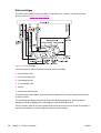
Power and regulatory label...................................................................................................14
Site requirements..................................................................................................................14
Space requirements.............................................................................................16
Physical specifications.........................................................................................17
Electrical specifications.........................................................................................................17
Environmental specifications................................................................................................18
Acoustic emissions...............................................................................................................18
Supply storage requirements ...............................................................................................19
Print media.............................................................................................................................................20
Print-media specifications.....................................................................................................20
Media to avoid.......................................................................................................................22
Media that can cause damage to the printer........................................................................22
Printing on special media......................................................................................................23
Transparencies....................................................................................................23
Glossy paper........................................................................................................24
Colored paper.......................................................................................................24
Printing images....................................................................................................24
Envelopes.............................................................................................................24
Labels...................................................................................................................25
Heavy paper.........................................................................................................25
HP LaserJet Tough paper....................................................................................26
Preprinted forms and letterhead..........................................................................26
Recycled paper....................................................................................................27
Weight equivalence table.....................................................................................28
Environmental product stewardship program........................................................................................29
Protecting the environment...................................................................................................29
Ozone production..................................................................................................................29
Power consumption..............................................................................................................29
Paper use..............................................................................................................................29
ENWW
iii
Plastics..................................................................................................................................29
HP LaserJet printing supplies...............................................................................................29
HP Printing Supplies Returns and Recycling Program Information.....................................29
Recycled paper.....................................................................................................................30
Material restrictions...............................................................................................................30
For more information.............................................................................................................30
Hewlett-Packard limited warranty statement.........................................................................................31
Declaration of conformity.......................................................................................................................32
Country/region laser safety statements.................................................................................................34
Canadian DOC regulations...................................................................................................34
EMI statement (Korea)..........................................................................................................34
VCCI statement (Japan).......................................................................................................34
Laser Statement for Finland.................................................................................................35
Japan power-cord statement.................................................................................................................35
2 Service approach
Service approach...................................................................................................................................38
Parts and supplies.................................................................................................................................39
Ordering parts, supplies, and accessories over the Internet................................................39
Ordering directly through the embedded Web server (for printers with network
connections)..........................................................................................................................39
Ordering directly through the HP Toolbox software (HP CLJ 4650 only).............................39
Exchange program................................................................................................................40
Supplies................................................................................................................................40
World Wide Web...................................................................................................................40
HP Service Parts Information...............................................................................................40
HP customer care..................................................................................................................................41
Online services.....................................................................................................................41
Telephone support................................................................................................................41
Software utilities, drivers, and electronic information...........................................................41
HP service information..........................................................................................................41
HP service agreements........................................................................................................41
HP support and information for Macintosh computers.........................................................42
Ordering related documentation and software .....................................................................................42
3 Installation and configuration
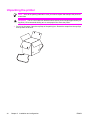
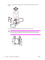
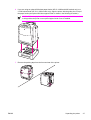
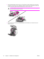
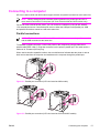
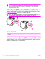
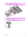
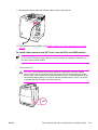
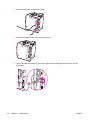
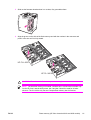
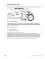
Unpacking the printer............................................................................................................................44
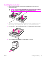
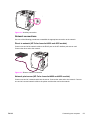
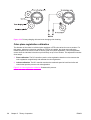
Installing the media tray.........................................................................................................................49
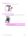
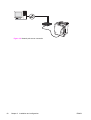
Connecting power..................................................................................................................................50
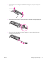
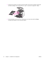
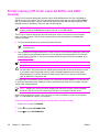
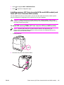
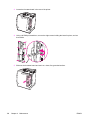
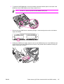
Installing the print cartridges..................................................................................................................50
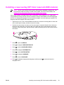
Installing a new overlay (HP Color LaserJet 4600 models)..................................................................53
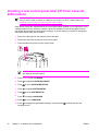
Installing a new control-panel label (HP Color LaserJet 4650 models)................................................54
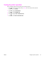
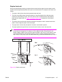
Testing the printer operation..................................................................................................................55
Using PowerSave .................................................................................................................................56
To set PowerSave Time.......................................................................................................56
To turn PowerSave on or off.................................................................................................56
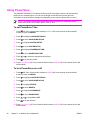
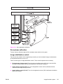
Connecting to a computer.....................................................................................................................57
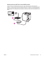
Parallel connections..............................................................................................................57
USB configuration (HP Color LaserJet 4610n and 4650 models)........................................58
Auxiliary connection configuration (HP Color LaserJet 4650 models).................................58
iv
ENWW
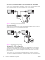
Network connections.............................................................................................................59
Direct to network (HP Color LaserJet 4600 and 4650 models)...........................59
Network print server (HP Color LaserJet 4600 and 4650 models)......................59
Network print server (HP Color LaserJet 4610n printer).....................................61
Peer-to-peer (direct to network, HP Color LaserJet 4600 and 4650 models).....62
Peer-to-peer (parallel)..........................................................................................62
Enhanced I/O (EIO) configuration.........................................................................................62
HP Jetdirect print servers.....................................................................................63
Available enhanced I/O interfaces.......................................................................63
NetWare networks................................................................................................63
Windows and Windows NT networks...................................................................64
AppleTalk networks..............................................................................................64
LocalTalk configuration........................................................................................64
LocalTalk network configuration..........................................................................64
UNIX and Linux networks.....................................................................................64
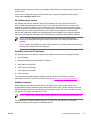
Wireless printing...................................................................................................................64
IEEE 802.11b standard........................................................................................64
Bluetooth..............................................................................................................65
Printer drivers........................................................................................................................................66
Available drivers....................................................................................................................67
Additional drivers..................................................................................................................68
Select the right printer driver for your needs........................................................................68
Printer driver Help.................................................................................................................68
Software for Macintosh computers........................................................................................................69
PPDs.....................................................................................................................................69
HP LaserJet Utility................................................................................................................69
Installing the printing system software..................................................................................................70
Installing Windows printing system software for direct connections....................................70
Installing Windows printing system software for networks...................................................71
To set up Windows-sharing to use the printer on a network ...............................................72
Installing Macintosh printing system software for networks.................................................72
Installing Macintosh printing system software for direct connections (USB, HP Color
LaserJet 4610n and 4650 models only)...............................................................................74
Installing the software after the parallel or USB cable has been connected........................75
Network configuration............................................................................................................................77
Configuring the printer for the network.................................................................................77
Configuring Novell NetWare frame type parameters............................................................77
Software for networks............................................................................................................................78
HP Web Jetadmin..................................................................................................................................78
UNIX......................................................................................................................................................79
Utilities...................................................................................................................................................79
Embedded Web server (HP Color LaserJet 4600 and 4650 models only)...........................................80
Features................................................................................................................................80
HP Toolbox (HP Color LaserJet 4650 models only).............................................................80
Other components and utilities.............................................................................................81
Setting network security on the printer..................................................................................................82
Locking the control panel......................................................................................................82
Levels of security ...............................................................................................82
Using an ASCII PJL escape sequence to set network security .........................83
ENWW
v
4 Maintenance
Cleaning the printer and accessories ..................................................................................................86
Cleaning spilled toner...........................................................................................................86
Vacuum specifications.........................................................................................86
Approximate replacement intervals for supply items.............................................................................87
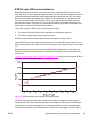
ETB life under different circumstances ................................................................................89
Locating supplies...................................................................................................................................91
Replacing supply items..........................................................................................................................92
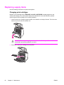
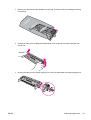
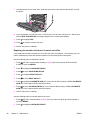
Changing print cartridges .....................................................................................................92
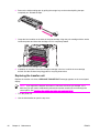
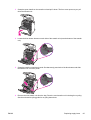
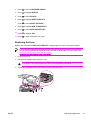
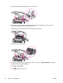
Replacing the transfer unit ...................................................................................................94
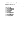
Replacing the transfer unit when it is not at end of life........................................96
Replacing the fuser ..............................................................................................................97
Replacing the fuser when it is not at end of life ..................................................99
Printer memory (HP Color LaserJet 4600 models).............................................................................100
Installing memory and font DIMMs (HP Color LaserJet 4600 models) .............................100
Enabling memory (HP Color LaserJet 4600 models)........................................102
Enabling the language font DIMM (HP Color LaserJet 4600 models)...............103
Checking DIMM installation (HP Color LaserJet 4600 models)........................103
Printer memory (HP Color LaserJet 4610n and 4650 models)...........................................................104
Installing memory (HP Color LaserJet 4610n and 4650 models) and fonts (HP Color
LaserJet 4650 models).......................................................................................................105
To install DDR memory DIMMs (HP Color LaserJet 4610n and 4650
models)...............................................................................................................105
To install a flash memory card (HP Color LaserJet 4610n and 4650
models)...............................................................................................................109
Enabling memory (HP Color LaserJet 4610n and 4650 models)......................113
To enable memory for Windows 98, ME, and NT (HP Color
LaserJet 4650 models)......................................................................113
To enable memory for Windows 2000 and XP (HP Color
LaserJet 4610n and 4650 models)....................................................113
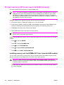
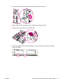
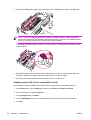
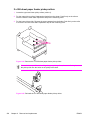
Installing an HP Jetdirect print server card (HP Color LaserJet 4600 and 4650 models only)...........114
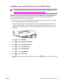
Installing an HP Jetdirect print server card (HP Color LaserJet 4610n model)..................................116
5 Theory of operation
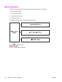
Basic operation....................................................................................................................................118
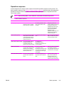
Operation sequence............................................................................................................119
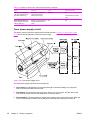
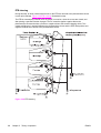
Engine-control system.........................................................................................................................120
DC controller circuit.............................................................................................................121
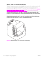
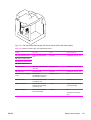
Motors, fans, and environment sensor...............................................................................122
Fuser power-supply circuit..................................................................................................124
Heater temperature control.................................................................................................126
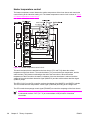
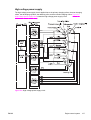
High-voltage power supply.................................................................................................127
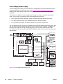
Low-voltage power supply..................................................................................................128
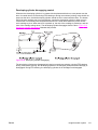
Formatter system................................................................................................................129
PowerSave..........................................................................................................................130
Input/output.........................................................................................................................131
Parallel interface................................................................................................131
Expanded I/O (HP Color LaserJet 4600 models)..............................................131
USB 1.1 connector (HP Color LaserJet 4610n and 4650 models)....................131
Flash (HP Color LaserJet 4600 models)............................................................131
vi
ENWW
Hard-disk accessory (HP Color LaserJet 4600 and 4650 models)...................131
CPU....................................................................................................................131
Printer memory...................................................................................................................132
Read-only memory.............................................................................................132
Random-access memory...................................................................................132
DIMM slots (HP Color LaserJet 4600 Series printer).........................................................132
Firmware DIMM (HP Color LaserJet 4600 models) ..........................................132
Flash memory (HP Color LaserJet 4610n and 4650 models)...........................132
Nonvolatile memory...........................................................................................132
PJL overview.......................................................................................................................133
PML.....................................................................................................................................133
Control panel.......................................................................................................................133
Laser/scanner assembly......................................................................................................................134
Scanner-motor control........................................................................................................135
Image-formation system......................................................................................................................136
Image-formation process....................................................................................................137
Print cartridges....................................................................................................................138
Memory tag........................................................................................................139
Toner-level detection..........................................................................................................139
Developer rotations............................................................................................140
Toner sensor......................................................................................................140
Photosensitive drum rotations............................................................................140
Developing cylinder disengaging control...........................................................141
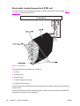
Electrostatic transfer/transport belt (ETB) unit....................................................................142
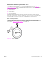
Electrostatic-latent-image-formation block.........................................................................143
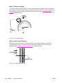
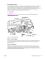
Step 1: Primary exposure...................................................................................143
Step 2: Primary charging....................................................................................144
Step 3: Laser beam exposure............................................................................144
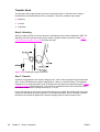
Development block.............................................................................................................145
Step 4: Toner charging.......................................................................................145
Step 5: Development..........................................................................................145
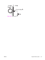
Transfer block.....................................................................................................................146
Step 6: Attaching................................................................................................146
Step 7: Transfer.................................................................................................146
Step 8: Separation.............................................................................................148
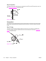
Fusing block........................................................................................................................148
Step 9: Fusing....................................................................................................148
Cleaning block....................................................................................................................149
Step 10: ETB cleaning.......................................................................................149
Step 11: Photosensitive drum cleaning.............................................................149
Calibration and cleaning.....................................................................................................150
ETB cleaning......................................................................................................152
Photosensitive drum cleaning............................................................................153
Color-plane registration calibration.....................................................................................154
Drum phase calibration.......................................................................................................155
Image stabilization control..................................................................................................155
Environmental change control (HP Color LaserJet 4610n and 4650 models). .156
Image density calibration control (DMAX).........................................................156
Image halftone calibration control (DHALF).......................................................157
Image density detection.....................................................................................158
ENWW
vii
Pickup/feed system.............................................................................................................................159
Pickup/feed unit..................................................................................................................161
Cassette detection and cassette paper-size detection......................................162
Overhead transparency detection......................................................................163
Small-size paper detection.................................................................................164
Feed-speed control............................................................................................165
Fuser/delivery unit...............................................................................................................166
Duplex feed unit..................................................................................................................167
500-sheet paper feeder.......................................................................................................................168
Pickup and feed operations................................................................................................169
2 x 500-sheet feeder............................................................................................................................170
Pickup and feed system......................................................................................................171
Cassette detection and cassette paper-size detection......................................172
6 Removal and replacement
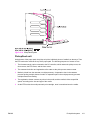
Introduction..........................................................................................................................................174
Repair notices.....................................................................................................................174
Caution regarding electrostatic discharge (ESD)...............................................................174
Required tools.....................................................................................................................174
Types of fasteners..............................................................................................................175
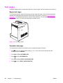
Supplies...............................................................................................................................................176
Print cartridges and ETB.....................................................................................................177
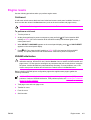
Covers and external components........................................................................................................178
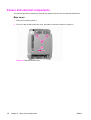
Rear cover..........................................................................................................................178
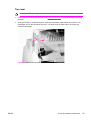
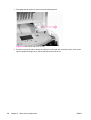
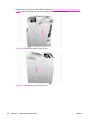
Top cover............................................................................................................................179
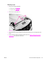
Rear top cover....................................................................................................................181
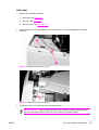
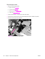
Left cover............................................................................................................................183
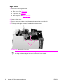
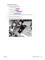
Right cover..........................................................................................................................184
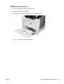
Multipurpose tray (tray 1)....................................................................................................185
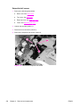
Front cover..........................................................................................................................186
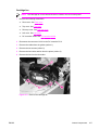
Control panel.......................................................................................................................187
Installing a new overlay (HP Color LaserJet 4600 models)...............................................189
Installing a new control-panel label (HP Color LaserJet 4650 models).............................190
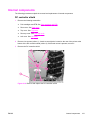
Internal components............................................................................................................................191
DC controller shield.............................................................................................................191
Internal components (front).................................................................................................192
Paper pickup unit...............................................................................................192
Paper pickup sensor PCA..................................................................................194
Cassette (tray 2) paper pickup rollers ...............................................................195
Paper pickup drive unit.......................................................................................196
Multipurpose tray pickup roller and separation pad...........................................197
Solenoids............................................................................................................199
Color registration detection unit.........................................................................200
Internal components (left side)...........................................................................................202
Environment sensor (HP Color LaserJet 4610n/4650 models only).................202
Drum drive units.................................................................................................203
Memory-tag antenna PCAs................................................................................209
Developing disengaging motor assembly..........................................................210
DC controller PCA..............................................................................................211
Memory controller PCA......................................................................................212
viii
ENWW
Cassette paper-size-detection switch................................................................213
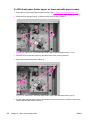
Internal components (rear).................................................................................................214
Formatter............................................................................................................214
Low-voltage power supply.................................................................................215
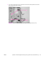
Power-supply fan (HP Color LaserJet 4610n and 4650 models)......................217
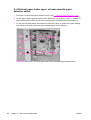
Formatter case...................................................................................................218
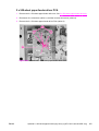
Laser/scanner components................................................................................220
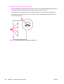
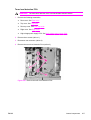
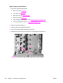
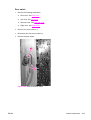
Remove the laser/scanner cover plate..............................................220
Remove the laser/scanner retaining bars.........................................222
To remove the laser/scanner assemblies.........................................224
Internal components (right side).........................................................................................225
High-voltage power supply PCA........................................................................225
Toner level detection PCA.................................................................................227
High-voltage contact blocks...............................................................................228
Door switch.........................................................................................................229
Internal components (top)...................................................................................................230
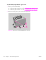
Fuser power supply PCA...................................................................................230
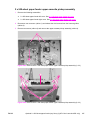
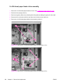
Fuser drive unit..................................................................................................232
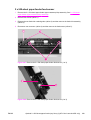
Fuser inlet paper sensor....................................................................................234
Fuser delivery sensor.........................................................................................235
Output-bin-full sensor.........................................................................................236
Cartridge fan.......................................................................................................237
Formatter fan......................................................................................................238
Optional 500-sheet paper feeder (HP Color LaserJet 4600 and 4650 models only)..........................239
500-sheet paper feeder top cover plate..............................................................................239
500-sheet paper feeder drive unit.......................................................................................240
500-sheet paper-feeder pickup rollers................................................................................242
500-sheet paper-feeder PCA..............................................................................................242
Optional 2 x 500-sheet paper feeder (tray 3/tray 4) (HP Color LaserJet 4650 only)..........................243
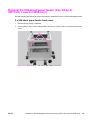
2 x 500-sheet paper feeder front cover..............................................................................243
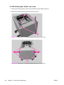
2 x 500-sheet paper feeder rear cover...............................................................................244
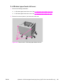
2 x 500-sheet paper feeder left cover.................................................................................245
2 x 500-sheet paper feeder right cover...............................................................................246
2 x 500-sheet paper feeder upper-cassette pickup assembly............................................247
2 x 500-sheet paper-feeder drive assembly.......................................................................248
2 x 500-sheet paper-feeder feed sensor............................................................................249
2 x 500-sheet paper feeder upper- or lower-cassette paper sensor..................................250
2 x 500-sheet paper feeder upper- or lower-cassette paper-detection switch...................252
2 x 500-sheet paper-feeder driver PCA..............................................................................253
2 x 500-sheet paper feeder pickup rollers..........................................................................254
7 Troubleshooting
Introduction..........................................................................................................................................256
Troubleshooting process.....................................................................................................................258
Pre-troubleshooting checklist..............................................................................................259
Troubleshooting basics ......................................................................................................261
Troubleshooting power-on .................................................................................................262
Printer-error troubleshooting ...............................................................................................................263
Status messages ...............................................................................................................263
Warning messages ............................................................................................................263
ENWW
ix
Error messages ..................................................................................................................263
Critical error messages ......................................................................................................263
Alphabetical printer messages (HP Color LaserJet 4600 models).....................................264
Alphabetical printer messages (HP Color LaserJet 4610n and 4650 models)..................279
Numerical printer messages (HP Color LaserJet 4600 models)........................................298
Numerical printer messages (HP Color LaserJet 4610n and 4650 models)......................311
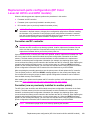
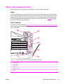
Replacement-parts configuration (HP Color LaserJet 4610n and 4650 models) ..............................329
Formatter and DC controller ..............................................................................................329
Formatter (new or previously installed in another printer) .................................................329
DC Controller (new or previously installed in another printer) ...........................................330
Paper-path troubleshooting ................................................................................................................331
Jams ...................................................................................................................................331
Jam locations......................................................................................................................331
Jam locations by error message ........................................................................................332
Jam recovery .....................................................................................................................333
To disable paper jam recovery...........................................................................334
Avoiding jams .....................................................................................................................334
Persistent jams ..................................................................................................................335
Basic troubleshooting for jams...........................................................................335
Data collection....................................................................................................335
General paper-path troubleshooting..................................................................336
Paper-path checklist...........................................................................................336
Jams in tray 1 ....................................................................................................337
Jams in tray 2 ....................................................................................................337
Jams in tray 3 or tray 3/tray 4 (2 x 500-sheet paper feeder, HP CLJ 4650
only) ...................................................................................................................338
Jams in the paper path ......................................................................................339
Jams in the top cover ........................................................................................340
Jams in the duplex path (HP CLJ 4600 and 4650 models only) ......................340
Media-transport troubleshooting .........................................................................................................341
Multiple pages are fed .......................................................................................................341
Media is wrinkled or folded.................................................................................................341
Paper is skewed .................................................................................................................342
Image-formation troubleshooting ........................................................................................................343
Online print-quality troubleshooting tools (HP Color LaserJet 4610n and 4650 models). .343
Print-quality problems associated with media....................................................................343
Overhead transparency defects .........................................................................................344
Print-quality problems that are associated with the environment.......................................344
Print-quality problems that are associated with jams.........................................................345
Print-quality troubleshooting pages ...................................................................................345
Understanding color variations ..........................................................................................345
Common causes of color variation.....................................................................345
Color selection process .....................................................................................................346
Matching colors ..................................................................................................................346
PANTONE®* color matching.............................................................................346
Swatch book color matching..............................................................................346
Using color..........................................................................................................................347
HP ImageREt 2400 (HP Color LaserJet 4600 models).....................................347
HP ImageREt 3600 (HP Color LaserJet 4610n and 4650 models)...................347
Paper selection..................................................................................................347
x
ENWW
sRGB..................................................................................................................347
Color options ......................................................................................................................348
Print in Grayscale ..............................................................................................348
Automatic or manual color adjustment..............................................................348
Manual color options..........................................................................................348
Halftone options.................................................................................................349
Neutral Grays.....................................................................................................349
Edge Control......................................................................................................349
RGB Color..........................................................................................................349
Adjusting color balance ......................................................................................................350
To adjust color density.......................................................................................350
Image defects troubleshooting ...........................................................................................................351
Light image ........................................................................................................................352
Light color ..........................................................................................................................352
Dark image .........................................................................................................................353
Dark color ...........................................................................................................................353
Completely blank image ....................................................................................................353
All black or solid color ........................................................................................................353
Dots in vertical lines ...........................................................................................................354
Dirt on the back of the paper .............................................................................................354
Dirt on the front of the paper ..............................................................................................355
Vertical lines .......................................................................................................................355
White vertical lines .............................................................................................................355
Horizontal lines ..................................................................................................................356
White horizontal lines .........................................................................................................356
Missing color ......................................................................................................................356
Blank spots ........................................................................................................................357
Poor fusing .........................................................................................................................357
Distortion or blurring ...........................................................................................................358
Smearing ............................................................................................................................358
Misplaced image ................................................................................................................358
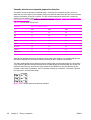
Repetitive defects troubleshooting.....................................................................................359
Interface troubleshooting ....................................................................................................................363
Communications checks.....................................................................................................363
EIO troubleshooting (HP CLJ 4600 and 4650 models only) .............................................363
AUTOEXEC.BAT standard configurations.........................................................................364
Parallel MS-DOS commands.............................................................................364
Printer Job Language (PJL) commands ............................................................................364
@PJL [Enter]......................................................................................................364
UEL ...................................................................................................................364
@PJL COMMENT..............................................................................................364
@PJL INFO CONFIG.........................................................................................365
@PJL INFO ID...................................................................................................365
@PJL INFO USTATUS......................................................................................365
@PJL INFO PAGECOUNT................................................................................365
@PJL JOB.........................................................................................................365
@PJL EOJ.........................................................................................................365
@PJL ECHO......................................................................................................365
@PJL USTATUS JOB=ON/OFF........................................................................365
@PJL USTATUSOFF........................................................................................366
ENWW
xi
Control-panel troubleshooting.............................................................................................................367
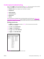
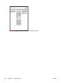
Printing a menu map ..........................................................................................................367
Information menu ...............................................................................................................369
Paper handling menu .........................................................................................................370
Configure device menu ......................................................................................................371
Printing menu ....................................................................................................371
Print quality menu .............................................................................................374
System setup menu ..........................................................................................376
I/O menu ............................................................................................................380
Resets menu .....................................................................................................381
Diagnostics menu ..............................................................................................................382
Service menu .....................................................................................................................383
Tools for troubleshooting.....................................................................................................................385
Embedded Web server (HP Color LaserJet 4600 and 4650 models only) .......................385
To open the embedded Web server...................................................................................385
Information tab...................................................................................................386
Settings tab........................................................................................................386
Networking tab ..................................................................................................387
Other links..........................................................................................................387
Printer Status and Alerts software .....................................................................................387
To specify which status messages appear........................................................388
To view status messages and information.........................................................388
Printer information pages....................................................................................................388
Menu map .........................................................................................................388
Configuration page ............................................................................................389
Supplies status page .........................................................................................392
Usage page .......................................................................................................394
Demo page.........................................................................................................395
File directory page .............................................................................................396
PCL font list page...............................................................................................396
PS font list page.................................................................................................398
RGB samples page (HP Color LaserJet 4610n and 4650 models)...................398
CMYK samples page (HP Color LaserJet 4610n and 4650 only).....................399
Diagnostics .........................................................................................................................................400
LED diagnostics .................................................................................................................400
Engine diagnostics .............................................................................................................401
Diagnostics mode...............................................................................................401
Diagnostics that put the engine into the special diagnostics mode...................401
Diagnostic tests..................................................................................................402
Individual diagnostic tests...................................................................................................403
Print the event log page ....................................................................................403
View the event log on the control-panel display ...............................................403
Print the PQ troubleshooting pages ..................................................................403
Disable cartridge check (special mode test)......................................................404
Paper path sensor test (HP Color LaserJet 4610n and 4650 models)..............404
Paper-path test ..................................................................................................405
Sensor Test (special mode test) .......................................................................405
Manual sensor test (special mode test; HP Color LaserJet 4610n and 4650
models)...............................................................................................................408
Component test (special mode test)..................................................................413
xii
ENWW
Print/Stop test ....................................................................................................418
Information menu...............................................................................................418
Configure device menu/printing menu...............................................................419
Configure device menu/resets menu.................................................................419
Configure device menu/print quality menu........................................................419
Test pages ..........................................................................................................................................420
Engine test page ................................................................................................................420
Formatter test page.............................................................................................................420
Engine resets.......................................................................................................................................421
Cold reset ...........................................................................................................................421
To perform a cold reset......................................................................................421
NVRAM initialization ..........................................................................................................421
To initialize NVRAM...........................................................................................422
Resetting the calibration values for the DC controller........................................................422
To reset the calibration values for the DC controller.........................................422
Hard disk initialization ........................................................................................................422
To initialize the hard disk....................................................................................422
Calibration bypass .............................................................................................................422
To bypass calibration.........................................................................................423
Calibrate Now (HP Color LaserJet 4600 models)..............................................................423
Quick Calibrate Now (HP Color LaserJet 4610n and 4650 models)..................................423
Full Calibrate Now (HP Color LaserJet 4610n and 4650 models).....................................424
Service menu.......................................................................................................................................425
Using the Service menu......................................................................................................425
Clear event log...................................................................................................425
Total page count................................................................................................425
Transfer kit count...............................................................................................425
Fuser kit count....................................................................................................425
Serial number.....................................................................................................425
Service ID ..........................................................................................................426
Restoring the Service ID...................................................................426
Converting the Service ID to an actual date.....................................426
Cold reset paper.................................................................................................427
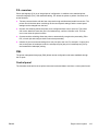
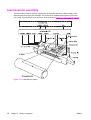
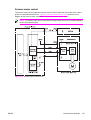
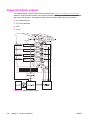
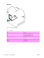
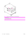
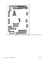
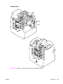
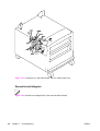
Diagrams.............................................................................................................................................428
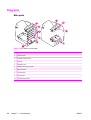
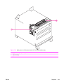
Main parts...........................................................................................................................428
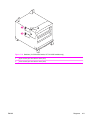
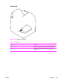
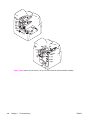
Switches .............................................................................................................................430
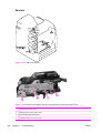
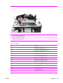
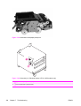
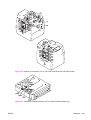
Sensors...............................................................................................................................432
Solenoids ...........................................................................................................................435
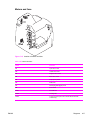
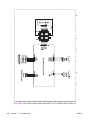
Motors and fans .................................................................................................................437
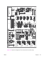
PCAs ..................................................................................................................................439
DC controller PCA ..............................................................................................................441
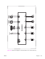
Connectors .........................................................................................................................443
General circuit diagram ......................................................................................................446
8 Parts and diagrams
Introduction..........................................................................................................................................452
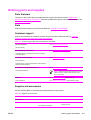
Ordering parts and supplies................................................................................................................453
Parts that wear....................................................................................................................453
Parts....................................................................................................................................453
Customer support...............................................................................................................453
ENWW
xiii
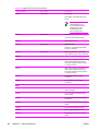
Supplies and accessories...................................................................................................453
Common fasteners..............................................................................................................459
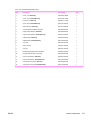
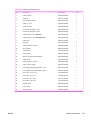
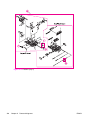
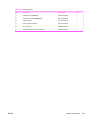
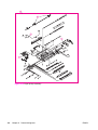
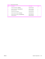
Illustrations and parts lists...................................................................................................................460
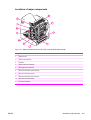
Locations of major components..........................................................................................461
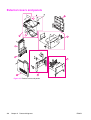
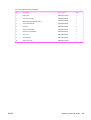
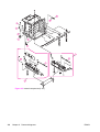
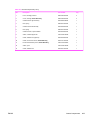
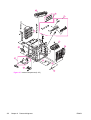
External covers and panels.................................................................................................................464
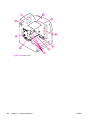
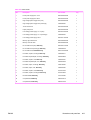
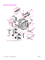
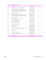
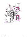
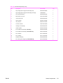
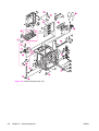
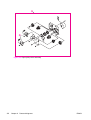
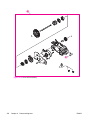
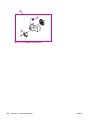
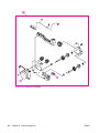
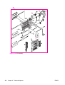
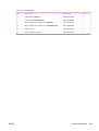
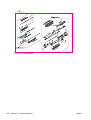
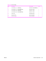
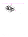
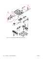
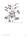
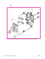
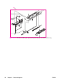
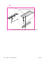
Internal components............................................................................................................................466
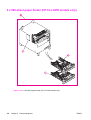
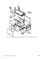
500-sheet paper feeder (HP CLJ 4600/4650 models only).................................................................492
2 x 500-sheet paper feeder (HP CLJ 4650 models only)....................................................................496
Alphabetical parts list...........................................................................................................................508
Numerical parts list..............................................................................................................................515
Index....................................................................................................................................................................523
xiv
ENWW
1
Product information
This chapter contains information about the following topics:
ENWW
●
Model configurations
●
Printer features
●
Printer assemblies
●
Identification, site requirements, and specifications
●
Print media
●
Environmental product stewardship program
●
Hewlett-Packard limited warranty statement
●
Declaration of conformity
●
Country/region laser safety statements
●
Japan power-cord statement
1
Model configurations
This manual describes the HP Color LaserJet 4600 models, the HP Color LaserJet 4610n model,
and the HP Color LaserJet 4650 models, which are referred to collectively as the HP Color LaserJet
4600 Series printers.
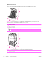
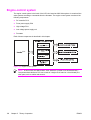
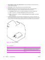
HP Color LaserJet 4600 Series printer
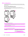
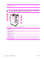
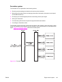
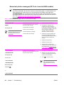
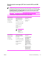
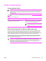
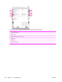
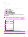
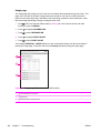
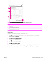
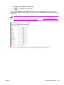
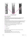
The following figures and table show the configuration for the various models of HP Color
LaserJet 4600 Series printer. The HP Color LaserJet 4600 printer and the HP Color LaserJet 4650
printer each come in five models.
1
3
2
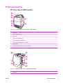
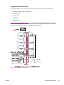
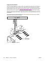
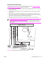
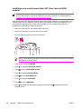
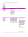
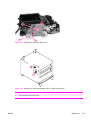
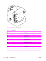
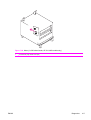
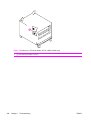
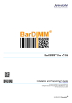
Figure 1-1 HP CLJ 4600 Series printers
1
HP Color LaserJet 4600, 4600n, 4600dn, 4650, 4650n, and 4650dn printer and the HP Color LaserJet 4610n printer
2
HP Color LaserJet 4600dtn, 4600hdn, and 4650dtn printer
3
HP Color LaserJet 4650hdn printer
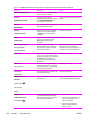
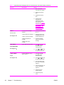
Table 1-1 HP Color LaserJet 4600 model configurations
Base model: HP Color LaserJet 4600 printer (product
number C9660A)
The HP CLJ 4600 printer is the base model, which includes
96 megabytes (MB) of synchronous dynamic random access
memory (SDRAM) and one 500-sheet input tray.
Callout 1 in Figure 1-1 HP CLJ 4600 Series printers shows
the HP Color LaserJet 4600 printer.
2
Chapter 1
Product information
ENWW
Table 1-1 HP Color LaserJet 4600 model configurations (continued)
HP Color LaserJet 4600n printer (product number C9692A)
The HP CLJ 4600n printer includes all of the features of the
base model plus an HP Jetdirect 610n print server (network
card).
Callout 1 in Figure 1-1 HP CLJ 4600 Series printers shows
the HP Color LaserJet 4600n printer.
HP Color LaserJet 4600dn printer (product number C9661A) The HP CLJ 4600dn printer includes all of the features of the
base model plus an HP Jetdirect 610n print server (network
card), automatic 2-sided printing (duplexing), an additional
500-sheet feeder, and 96 MB of SDRAM.
Callout 1 in Figure 1-1 HP CLJ 4600 Series printers shows
the HP Color LaserJet 4600dn printer.
HP Color LaserJet 4600dtn printer (product number C9662A) The HP CLJ 4600dtn printer includes all of the features of the
base model plus an HP Jetdirect 610n print server (network
card) and automatic 2-sided printing (duplexing), an
additional 500-sheet feeder, and 160 MB of SDRAM.
Callout 2 in Figure 1-1 HP CLJ 4600 Series printers shows
the HP Color LaserJet 4600dtn printer.
HP Color LaserJet 4600hdn printer (product number
C9663A)
The HP CLJ 4600hdn printer includes all of the features of
the base model with an HP Jetdirect 610n print server
(network card) and automatic 2-sided printing (duplexing), an
additional 500-sheet feeder, a hard disk, and 160 MB of
SDRAM.
Callout 2 in Figure 1-1 HP CLJ 4600 Series printers shows
the HP Color LaserJet 4600hdn printer.
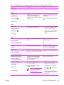
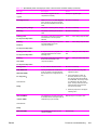
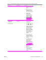
Table 1-2 HP Color LaserJet 4610n printer
HP Color LaserJet 4610n printer (product number Q7732A)
The HP CLJ 4610n includes 128 MB of dual-data-rate
(DDR) SDRAM plus 32 MB of additional memory on the
formatter board for a total of 160 MB of memory.
This model includes a 500-sheet input tray.
The printer also includes an HP Jetdirect 175x external print
server that is connected to the USB port. It also has an IEEEcompliant parallel connection.
Callout 1 in Figure 1-1 HP CLJ 4600 Series printers shows
the HP Color LaserJet 4610n printer.
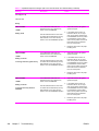
Table 1-3 HP Color LaserJet 4650 model configurations
Base model: HP Color LaserJet 4650 printer (product
number Q3668A)
The HP CLJ 4650 printer is the base model, which includes
128 MB of DDR SDRAM, plus 32 MB of additional memory
on the formatter board for a total of 160 MB of memory, and
a 500-sheet input tray.
The printer provides three enhanced input/output (EIO)
slots, wireless connectivity, an auxiliary port, a universal
serial bus (USB) connection, and a standard bidirectional
parallel cable interface (IEEE-1284-C compliant).
Callout 1 in Figure 1-1 HP CLJ 4600 Series printers shows
the HP Color LaserJet 4650 printer.
ENWW
Model configurations
3
Table 1-3 HP Color LaserJet 4650 model configurations (continued)
HP Color LaserJet 4650n printer (product number Q3669A)
The HP CLJ 4650n printer includes all of the features of the
base model plus an HP Jetdirect 620n print server (network
card).
Callout 1 in Figure 1-1 HP CLJ 4600 Series printers shows
the HP Color LaserJet 4650n printer.
HP Color LaserJet 4650dn printer (product number Q3670A)
The HP CLJ 4650dn printer includes all of the features of the
base model plus an HP Jetdirect 620n print server (network
card) and automatic 2-sided printing (duplexing).
Callout 1 in Figure 1-1 HP CLJ 4600 Series printers shows
the HP Color LaserJet 4650dn printer.
HP Color LaserJet 4650dtn printer (product number Q3671A)
The HP CLJ 4650dtn printer includes all of the features of
the base model plus an HP Jetdirect 620n print server
(network card), automatic 2-sided printing (duplexing), an
additional 500-sheet feeder.
This model has 256 MB of DDR SDRAM, plus 32 MB of
additional memory on the formatter board for a total of 288
MB of memory.
Callout 2 in Figure 1-1 HP CLJ 4600 Series printers shows
the HP Color LaserJet 4650dtn printer.
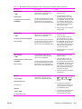
HP Color LaserJet 4650hdn printer (product number Q3672A) The HP CLJ 4650hdn printer includes all of the features of
the base model plus an HP Jetdirect 620n print server
(network card), automatic 2-sided printing (duplexing), a 2 x
500-sheet feeder, and a hard drive.
This model has 256 MB of DDR SDRAM, plus 32 MB of
additional memory on the formatter board for a total of 288
MB of memory.
Callout 3 in Figure 1-1 HP CLJ 4600 Series printers shows
the HP Color LaserJet 4650hdn printer.
4
Chapter 1
Product information
ENWW
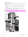
Printer features
This printer combines the quality and reliability of HP printing with the following features. For more
information about printer features, go to one of the following Web sites:
■
HP Color LaserJet 4600 models: www.hp.com/support/clj4600
■
HP Color LaserJet 4610n printer: www.hp.com/support/clj4610
■
HP Color LaserJet 4650 models: www.hp.com/support/clj4650
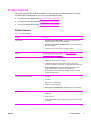
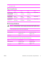
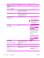
Printer features
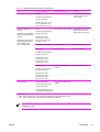
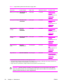
Table 1-4 Printer features
Feature
Description
Performance
■
HP Color LaserJet 4600 models: 17 pages per minute (ppm) on
letter-sized paper, 16 ppm on A4-sized paper.
■
HP Color LaserJet 4610n and 4650 models: 22 ppm on letter-sized
and A4-sized paper.
■
All models print on transparencies and glossy paper.
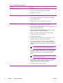
Memory
For information about printer memory, see Table 1-1 HP Color
LaserJet 4600 model configurations.
User interface
■
Graphical display on the control panel.
■
Enhanced Help with animated graphics.
■
Embedded Web server to gain access to support and to order
supplies (on network-connected HP CLJ 4600 and 4650 models only).
■
HP CLJ 4650 models: HP LaserJet Toolbox software to provide
printer status and alerts, configure printer settings, view
documentation and troubleshooting information, and print internal
printer information pages.
■
HP PCL 6.
■
HP PCL 5c.
■
PostScript® 3 emulation (PS).
■
Automatic language switching.
■
HP CLJ 4610n and 4650 models: Portable document format (PDF).
■
Job storage (only for HP CLJ 4600 and 4650 models that contain
hard disks).
■
Fonts and forms.
■
Personal identification number (PIN) printing (for printers that contain
hard disks).
Supported printer personalities
Storage features
ENWW
Printer features
5
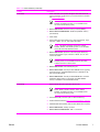
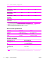
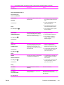
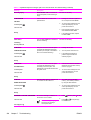
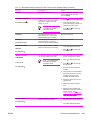
Table 1-4 Printer features (continued)
Feature
Description
Environmental features
■
PowerSave setting.
■
High content of recyclable components and materials.
■
ENERGY STAR® compliant.
■
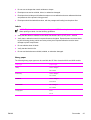
80 internal fonts are available for both PCL and PostScript emulation.
■
80 printer-matching screen fonts in TrueType format are available
with the software solution.
■
HP Web Jetadmin supports forms and fonts on the disk.
■
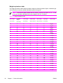
Prints on media from 77 mm x 127 mm (3 inches x 5 inches) up to
legal size (216 mm x 355 mm; 8.5 inches x 14 inches).
■
HP Color LaserJet 4600 models: Prints on media of weights from
60 g/m2 to 176 g/m2 (16 lb to 47 lb).
■
HP Color LaserJet 4610n and 4650 models: Prints on media of
weights from 60 g/m2 to 199 g/m2 (16 lb to 53 lb).
■
Prints on a wide range of media types including glossy, labels,
overhead transparencies, and envelopes.
■
Accepts multiple gloss levels.
■
Includes a 500-sheet input tray (tray 2) that supports letter-, legal-,
executive-, JIS B5-, A4-, A5-, and custom-size media.
■
An optional 500-sheet paper feeder (tray 3) that supports letter-,
legal-, executive-, JIS B5-, A4-, A5-, and custom-size media (the tray
is standard on HP Color LaserJet 4600dtn, 4600hdn, and 4650dtn
printers).
Fonts
Paper handling
NOTE The optional 500-sheet paper feeder is available
only for the HP Color LaserJet 4600 and 4650 models.
■
An optional 2 x 500-sheet paper feeder (tray 3/tray 4) that supports
letter-, legal-, executive-, JIS B5-, 16K-, A4-, A5-, and custom-size
media (the tray is standard on the HP Color LaserJet 4650hdn
printer).
NOTE The 2 x 500-sheet feeder is available only for the
HP Color LaserJet 4650 models.
6
Chapter 1
Product information
■
Includes built-in 2-sided printing on the HP Color LaserJet 4600dn,
4600dtn, 4600hdn, 4650dn, 4650dtn, and 4650hdn printers (not
included with the HP Color LaserJet 4610n printer).
■
Includes a 250-sheet face-down output bin.
ENWW
Table 1-4 Printer features (continued)
Feature
Description
Accessories
■
Printer hard disk, which provides storage for fonts and macros as
well as job storage. To determine if your model contains a hard disk,
see Model configurations.
NOTE The hard disk is standard on the HP Color LaserJet
4600hdn and 4650hdn printers. It is not available for the
HP Color LaserJet 4610n printer.)
■
HP CLJ 4600 models: Dual inline memory modules (DIMMs).
■
HP CLJ 4610n and 4650 models: 32 MB CompactFlash memory
(with firmware).
■
Printer stand.
■
Optional 500-sheet paper feeder (tray 3) that supports letter-, legal-,
executive-, JIS B5-, A4-, A5-, and custom-size media.
NOTE The feeder is standard on HP Color LaserJet
4600dtn, 4600hdn, and 4650dtn printers. It is not available
for the HP Color LaserJet 4610n printer.
■
HP CLJ 4650 models: Optional 2 x 500-sheet paper feeder (tray
3/4) that supports letter-, legal-, executive-, JIS B5-, A4-, A5-, and
custom-size media.
NOTE The feeder is standard on the HP Color LaserJet
4650hdn printer. It is not available for the HP CLJ 4600
models or the HP CLJ 4610n printer.
Connectivity
■
HP CLJ 4600 models: Fast InfraRed (FIR) pod.
■
HP CLJ 4610n model: One 200-pin DDR SDRAM slot for upgrading
the printer memory. The DDR SDRAM memory is available in 128,
256, and 512 MB modules.
■
HP CLJ 4650 models: Two 200-pin DDR SDRAM slots. One slot is
available for adding memory to the printer. The DDR SDRAM
memory is available in 128 and 256 MB modules.
■
Optional enhanced input/output (EIO) network card.
NOTE The network card is standard on HP Color LaserJet
4600n, 4600dn, 4600dtn, 4600hdn, 4650n, 4650dn,
4650dtn, and 4650hdn printers. It is not available for the
HP Color LaserJet 4610n printer.
ENWW
■
Fast InfraRed (FIR) connection (HP CLJ 4600 models only).
■
HP Web Jetadmin software (www.hp.com/go/wegjetadmin_software).
■
Standard bidirectional parallel cable interface (IEEE-1284 compliant).
■
HP CLJ 4650 models: Auxiliary connector.
■
HP CLJ 4610n and 4650 models: USB 1.1 connection.
Printer features
7
Table 1-4 Printer features (continued)
Feature
Description
NOTE HP Color LaserJet 4610n and 4650 models: Both
USB and parallel connections are supported, but they cannot be
used at the same time.
Supplies
8
Chapter 1
Product information
■
A supplies-status page contains information about toner level, page
count, and estimated pages remaining.
■
Cartridges feature a no-shake design.
■
The printer checks for authentic HP print cartridges at cartridge
installation.
■
HP Color LaserJet 4600 and 4650 models: Internet-enabled supplyordering capabilities (by using the embedded Web server).
ENWW
Printer assemblies
HP Color LaserJet 4600 models
Figure 1-2 Front view, HP Color LaserJet 4600 models
1
Output bin
2
Printer control panel
3
Top cover
4
Front cover (includes tray 1)
5
Tray 2 (500-sheet standard tray)
6
Tray 3 (500-sheet paper feeder; optional)
7
On/off switch
8
Access to print cartridge, transfer unit, and fuser
Figure 1-3 Back view, HP Color LaserJet 4600 models
1
ENWW
Output bin
Printer assemblies
9
2
On/off switch
3
Tray 3 500-sheet paper feeder (optional)
4
EIO connections (3 total)
5
Memory access
6
Fast InfraRed (FIR) connection
7
Parallel connection
8
Power connection
HP Color LaserJet 4610n printer
1
2
3
6
4
5
7
Figure 1-4 Front view, HP Color LaserJet 4610n printer
10
1
Output bin
2
Printer control panel
3
Top cover
4
Front cover (includes tray 1)
5
Tray 2 (500–sheet standard tray)
6
Access to print cartridges, transfer unit, and fuser
7
On/off switch
Chapter 1
Product information
ENWW
Figure 1-5 Back view, HP Color LaserJet 4610n printer
1
Output bin
2
Parallel connection
3
On/off switch
4
Memory access
5
1.1 USB connection
HP Color LaserJet 4650 models
Figure 1-6 Front view, HP Color LaserJet 4650 models
ENWW
1
Output bin
2
Printer control panel
3
Top cover
4
Front cover (includes tray 1)
5
Tray 2 (500-sheet standard tray)
6
Access to print cartridges, transfer unit, and fuser
Printer assemblies
11
7
On/off switch
8
Tray 3/tray 4 (optional)
NOTE The optional 500-sheet paper feeder (tray 3) and the optional 2 x 500-sheet input tray
(tray 3 and tray 4) cannot be installed in the printer at the same time.
Figure 1-7 Back view, HP Color LaserJet 4650 models
12
1
Output bin
2
Auxiliary connector
3
Parallel connection
4
On/off switch
5
EIO connection (3 total)
6
Memory access
7
1.1 USB connection
8
Tray 3/tray 4 (optional)
Chapter 1
Product information
ENWW
Identification, site requirements, and specifications
The following sections describes printer identification, site requirements, and specifications.
Model and serial numbers
The model number and serial numbers are listed on identification labels located on the rear of the
printer. The model number is alphanumeric, such as C9660A for an HP Color LaserJet 4600 printer.
The serial number contains information about the country/region of origin, the printer version,
production code, and the production number of the printer.
NOTE This manual describes the HP Color LaserJet 4600 Series printer, including the HP
Color LaserJet 4600 models, the HP Color LaserJet 4610n printer, and the HP Color LaserJet
4650 models.
production number
country/region
printer version
of origin model (product) number
production code
Hewlett-Packard
50/60 Hz. 115V
11311 Chinden Blvd.
Model No.: Q3668
Boise, Idaho 83704
U.S.A.
Serial No.: JPBB605112
Assembled in U.S.A. printer engine made in Japan
Figure 1-8 Model and serial number label
ENWW
Model name
Product/model number
HP Color LaserJet 4600
C9660A
HP Color LaserJet 4650
Q3668A
HP Color LaserJet 4600n
C9692A
HP Color LaserJet 4610n
Q7732A
HP Color LaserJet 4650n
Q3669A
HP Color LaserJet 4600dn
C9661A
HP Color LaserJet 4650dn
Q3670A
HP Color LaserJet 4600dtn
C9662A
HP Color LaserJet 4650dtn
Q3671A
HP Color LaserJet 4600hdn
C9663A
HP Color LaserJet 4650hdn
Q3672A
Identification, site requirements, and specifications
13
Power and regulatory label
The identification labels on the rear of the printer also contain power-rating and regulatory information.
CAUTION Converting the voltage on the printer can damage the printer. Do not use any
voltage other than the operating voltage. Any attempt to convert operating voltages will void
the product warranty (for example, attempting to change a 110 V printer to a 220 V printer).
Figure 1-9 Power and regulatory label
Site requirements
The printer must be kept in an appropriate location to maintain the performance level that has been
set at the factory. In particular, be sure that the environment adheres to the specifications listed in
this chapter.
The following are recommendations for the printer location and placement.
14
Chapter 1
Product information
ENWW
Make sure that the printer installation location has the following attributes:
■
A well-ventilated, dust-free area
■
A hard, level surface (with not more than a 2° angle)
■
For the HP Color LaserJet 4600, 4600n, and 4600dn, the surface must support at least 37 kg
(81 lb).
■
For the HP Color LaserJet 4600dtn and 4600hdn, the surface must support at least 44 kg
(97 lb).
■
For the HP Color LaserJet 4610n, the surface must support at least 36 kg (80 lb).
■
For the HP Color LaserJet 4650, 4650n, and 4650dn, the surface must support at least 36 kg
(80 lb).
■
For the HP Color LaserJet 4650dtn, the surface must support at least 44 kg (97 lb).
■
A level surface that supports all four corners of the printer
■
A constant temperature and humidity (not near water sources, humidifiers, air conditioners,
refrigerators, or other major appliances).
CAUTION The HP Color LaserJet 4650hdn must not be installed on an elevated surface.
Always install the HP CLJ 4650hdn printer on a hard, level floor.
Make sure to keep the printer away from the following environmental features:
ENWW
■
Direct sunlight, dust, open flames, or water
■
The direct flow of exhaust from air ventilation systems
■
Magnets and devices that emit a magnetic field
■
Areas that experience vibration
■
Walls or other objects
Identification, site requirements, and specifications
15
Space requirements
The HP Color LaserJet 4600 Series printers must have the following clearance space.
Figure 1-10 Space requirements for the HP Color LaserJet 4600 Series printer (except for the
HP Color LaserJet 4600dtn/4600hdn/4650dtn/4650hdn printer)
1
530 mm (20.9 inches)
2
1294 mm (50.9 inches)
3
804 mm (31.7 inches)
NOTE
More vertical space is required for models that have additional trays.
Figure 1-11 Space requirements for the HP Color LaserJet 4650hdn printer
1
16
530 mm (20.9 inches)
Chapter 1
Product information
ENWW
2
1294 mm (50.9 inches)
3
1373 mm (54.1 inches)
Physical specifications
Product
Height
Depth
Width
Weight
HP Color LaserJet
4600, 4600n, 4600dn,
4610n, 4650, 4650n,
and 4650dn printers
566 mm
480 mm
456 mm
37 kg (81.6 lbs)
(22.3 inches)
(18.9 inches)
(18.0 inches)
HP Color LaserJet
4600dtn, 4600hdn,
and 4650dtn printers
654 mm
480 mm
456 mm
(25.7 inches)
(18.9 inches)
(18.0 inches)
HP Color LaserJet
4650hdn printer
1035 mm
645 mm
460 mm
(40.7 inches)
(25.4 inches)
(18.1 inches)
44 kg (97.0 lbs)
66 kg (146.6 lbs)
Electrical specifications
WARNING! Power requirements are based on the country/region where the printer is sold.
Do not convert operating voltages. This can damage the printer and void the product warranty.
Table 1-5 Power requirements for the HP Color LaserJet 4600 models
Item
110-volt models
220-volt models
Power requirements
100–127 V (-10%, +6%)
220–240 V (-10%, +6%)
50/60 Hz (+/-2 Hz)
50/60 Hz (+/-2 Hz)
6 amps
3 amps
Rated current
Table 1-6 Power requirements for the HP Color LaserJet 4610n and 4650 models
Item
110-volt models
220-volt models
Power requirements
100–127 V (+/-10%)
220–240 V (+/-10%)
50/60 Hz (+/-2 Hz)
50/60 Hz (+/-2 Hz)
6 amps
3 amps
Rated current
ENWW
Identification, site requirements, and specifications
17
Table 1-7 Power consumption, average (in watts)1
Printing4
Ready4
PowerSave
Off
HP Color LaserJet
4600 models (110 volt
models)
426 W
34 W
30 W
0W
HP Color LaserJet
4600 models (220 volt
models)
430 W
36 W
32 W
0W
HP Color LaserJet
4610n and 4650
models (except HP
Color LaserJet
4650hdn printer)
560 W
38 W
26 W
0.3 W
HP Color LaserJet
4650hdn printer
560 W
40 W
31 W
0.3 W
Product model3, 3
Product model34
1
2
3
4
Values are subject to change. See www.hp.com/support/clj4600, www.hp.com/support/clj4610, or www.hp.com/support/
clj4650 for current information. The PowerSave default activation time is 30 minutes.
Power reported is highest value measured for color and monochrome printing using all standard voltages.
Default time from Ready mode to PowerSave = 30 minutes.
Maximum heat dissipation for all models in Ready mode = 137 BTU/Hour.
Environmental specifications
Specification
Recommended
Allowed
Temperature
17 to 25°C (62.6 to 77°F)
10 to 30°C (50 to 86°F)
Humidity
30 to 70% relative humidity (RH)
10 to 80% RH
Altitude
not applicable
0 to 2600 m (0 to 8530 ft)
Acoustic emissions
1
18
Sound Power Level 1 (SPL)
Declared Per ISO 9296
Active (22 ppm letter)
LWAd=6.5 Bels (A) [65 dB (A)]
Idle
LWAd=5.0 Bels (A) [50 dB (A)]
SPL - Bystander Position
Declared Per ISO 9296
Active (22 ppm letter)
LpAm=51 dB (A)
Idle
LpAm=34 dB (A)
Values are subject to change. See www.hp.com/support/clj4600, www.hp.com/support/clj4610, or www.hp.com/support/
clj4650 for current information. The PowerSave default activation time is 30 minutes.
Chapter 1
Product information
ENWW
Supply storage requirements
The life of supplies is greatly affected by their storage environment. Use storage requirements to
determine the shelf life of stored supplies.
Table 1-8 Supply storage requirements
Item
Storage time
Storage condition
Temperature
Normal (maximum of 2.5 years)
0° to 35°C (32° to 95°F)
Severe (maximum of 18 days)
High 35° to 40°C (95° to 104°F)
Low 0° to -20°C (32° to -4°F)
Maximum temperature change rate
40° to 15°C (104° to 59°F) within 3
minutes
-20° to 25°C (-4° to 77°F) within 3
minutes
Humidity
Normal (maximum of 2.5 years)
35% to 85% RH
Severe (maximum of 18 days)
High 85% to 95% RH
Low 10% to 35% RH
1
ENWW
Atmospheric pressure
460 to 760 mm Hg (18.1 to 29.9 inches
Hg)
Storage time1
2.5 years
The average storage time includes use time. Use cartridges within 2.5 years of the date code on the cartridge.
Identification, site requirements, and specifications
19
Print media
The following sections describe print media that can be used in the HP Color LaserJet 4600 Series
printer.
Print-media specifications
For optimum results, use conventional 75-g/m2 (20-lb) photocopy paper. Verify that the paper is of
good quality and is free of cuts, nicks, tears, spots, loose particles, dust, wrinkles, curls, or bent
edges.
■
To order supplies in the U.S., go to www.hp.com/go/ljsupplies.
■
To order supplies worldwide, go to www.hp.com/ghp/buyonline.html.
■
To order accessories, go to www.hp.com.
■
For additional information about supported media weights and sizes, go to www.hp.com/support/
ljpaperguide.
The following table contains information about the types of print media that are supported for the
various paper-handling features.
Table 1-9 Supported media specifications
Tray
Supported media
Media specifications
Capacity
Tray 1
Paper
HP Color LaserJet 4600
models: 60 to 176 g/m2 (16
to 47 lb)
100 sheets of 75-g/m2 (20lb) paper. Do not load more
than the maximum stack
height of 10 mm (0.6 in)
A4/Letter, Legal, Executive,
JIS, B5, A5, Custom
Minimum size: 76 x 127 mm
(3 x 5 in) Maximum size: 216
x 356 mm (8.5 x 14 in)
Transparencies
HP Color LaserJet 4610n
and 4650 models: 60 to
199 g/m2 (16 to 53 lb)
0.13 mm (5 mil)
Maximum stack height of
10 mm (0.6 in)
0.13 mm (5 mil)
Maximum stack height of 10
mm (0.6 in)
75-g/m2 to 120-g/m2(20-lb to
32-lb)
maximum stack height of
10 mm (0.6 in)
Maximum weight: 105-g/m2
(28-lb bond)
Limit of 20
A4/Letter
Glossy film
A4/Letter, Legal, Executive,
JIS, B5, A5, Custom
Minimum size: 76 x 127 mm
(3 x 5 in) Maximum size: 216
x 356 mm (8.5 x 14 in)
Glossy paper
A4/Letter, Legal, Executive,
JIS, B5, A5, Custom
Minimum size: 76 x 127 mm
(3 x 5 in) Maximum size: 216
x 356 mm (8.5 x 14 in)
Envelopes
Com10, Monarch, C5, DL, B5
20
Chapter 1
Product information
ENWW
Table 1-9 Supported media specifications (continued)
Tray
Supported media
Media specifications
Capacity
Do not load more than the
maximum stack height of
10 mm (0.6 in)
Labels1
A4/Letter, Legal, Executive,
JIS, B5, A5, Custom
Minimum size: 76 x 127 mm
(3 x 5 in). Maximum size:
216 x 356 mm (8.5 x 14 in)
Tray 2 (included for all
models)
Optional tray 3 (available for
the HP CLJ 4600 and 4650
models)
Optional tray 3/tray4 (the 2 x
500-sheet paper feeder is
only available for the
HP CLJ 4650 models) 2 3
Paper
60- to 105-g/m2(16- to 28-lb)
500 sheets of 75-g/m2 (20–
lb) paper. Maximum stack
height of 50 mm (2 inches)
Transparencies A4/Letter
0.13 mm (5 mil)
Limit of 100 sheets
Glossy film
0.13 mm (5 mil)
Limit of 100 sheets
75-g/m2 to 120-g/m2 (20-lb
to 32-lb)
Limit of 200 sheets
A4/Letter, Legal, Executive,
JIS, B5, A5, Custom
Minimum size: 148 x
210 mm (5.8 x 8.2 in).
Maximum size: 216 x 356
mm (8.5 x 14 in)
A4/Letter, Legal, Executive,
JIS, B5, A5, Custom
Minimum size: 148 x
210 mm (5.8 x 8.2 in).
Maximum size: 216 x
356 mm (8.5 x 14 in)
Glossy paper
A4/Letter, Legal, Executive,
JIS, B5, A5, Custom
Minimum size: 148 x
210 mm (5.8 x 8.2 in).
Maximum size: 216 x
356 mm (8.5 x 14 in)
Duplex printing
Paper, glossy paper
A4/Letter, Legal, Executive,
JIS, B5, A5, Custom
75-g/m2 to 105-g/m2 (20-lb
to 28-lb)
Custom paper sizes are not
supported for 2-sided printing.
1
2
3
Tray 1 only.
Tray 2, tray 3, and tray 3/tray 4 do not support the range of custom sizes that tray 1 does.
Tray 2, tray 3, and tray 3/tray 4 use custom size, specifically for B5 ISO.
NOTE Use only HP-supported transparencies (HP part number C2934A, Letter size;
C2936A, A4 size).
ENWW
Print media
21
Media to avoid
This printer can handle many types of media. Using media outside the printer's specifications will
cause a loss of print quality and increase the incidence of jams.
■
Do not use paper that is too rough.
■
Do not use paper that contains cutouts or perforations other than standard three-hole punched
paper.
■
Do not use multipart forms.
■
Do not use paper that has already been printed on or fed through a photocopier or printer.
■
Do not use paper that contains a watermark if you are printing solid patterns.
Media that can cause damage to the printer
In rare circumstances media can damage the printer. To prevent possible damage, do not use the
following media:
22
■
Do not use paper that is embossed or coated unless it is specifically recommended for use in this
printer.
■
Do not use paper that contains irregularities such as tabs or staples.
■
Do not use letterhead paper that was produced by using low temperature dyes or thermography.
Preprinted forms or letterhead must use inks that can tolerate 190°C (374°F) for 0.1 second.
■
Do not use any media that produces hazardous emissions, or that melts, offsets, or discolors
when exposed to 190°C (374°F) for 0.1 second.
■
Do not use transparencies that are designed for use with Inkjet printers or other low-temperature
printers. Use only transparencies that are specified for use with HP Color LaserJet printers.
Chapter 1
Product information
ENWW
Printing on special media
Use these guidelines when printing on special types of media.
■
For optimum results, use conventional 75-g/m2 (20-lb) xerographic paper.
■
Verify that the paper is of good quality and free of cuts, nicks, tears, spots, loose particles, dust,
wrinkles, curls, or bent edges.
NOTE Special media such as envelopes, transparencies, custom-size paper, or media that
is heavier than 120-g/m2 should be fed only from tray 1.
To print on any special media, use the following procedure.
1
Load the media in a tray.
2
When the printer prompts you for the paper type, select the correct media type for the media that
is loaded in the tray. For example, select HIGH GLOSS (HP Color LaserJet 4650 models only)
when loading high-gloss laser paper.
3
In the software program or the printer driver, set the media type to match the media type that is
loaded in the tray.
NOTE For the best print quality, always verify that the media type that is selected on the
printer control panel and the media type that is selected in the software program or printer
driver match the type of media that is loaded in the tray.
Transparencies
When printing on transparencies, use the following guidelines:
■
Handle transparencies by the edges. Oils from your fingers that are deposited on the
transparency can cause print-quality problems.
■
Use only overhead transparencies that are recommended for use in this printer. Hewlett-Packard
Company recommends using HP Color LaserJet Transparencies with this printer. HP products
are designed to work together for optimum printing results.
■
In either the software program or the driver, select TRANSPARENCY as the media type, or print
from a tray that is configured for transparencies.
CAUTION Transparencies that are not designed for LaserJet printing will melt in the printer,
causing damage to the printer.
Table 1-10 Printing on transparencies
ENWW
Description
Specifications
Electrical surface resistivity
2.0 to 15 ohms by 10 ohms per square inch.
Fusing compatibility
Materials must not discolor, melt, offset, or release
hazardous emissions when heated to 190ºC (374ºF) for 0.1
second.
Caliper (thickness)
0.12 mm (0.0048 inch) to 0.13 mm (0.0052 inch).
Print media
23
Glossy paper
■
In either the software program or the driver, select GLOSSY, HEAVY, or HIGH GLOSS (HP
Color LaserJet 4650 models only) as the media type, or print from a tray that is configured for
glossy paper.
■
Use the control panel to set the media type to GLOSSY for the input tray that is being used.
■
Because this setting affects all print jobs, return the printer to its original settings after the job has
printed.
NOTE Hewlett-Packard Company recommends using HP Color LaserJet High Gloss paper
with the HP Color LaserJet 4650 printer. HP products are designed to work together for
optimum printing results. If HP Color LaserJet High Gloss paper is not used with the printer,
print quality might be compromised.
Colored paper
■
Colored paper should be of the same high quality as white xerographic paper.
■
Pigments used must be able to withstand the printer’s fusing temperature of 190°C (374°F) for
0.1 second without deterioration.
■
Do not use paper that contains a colored coating that was added after the paper was produced.
■
The printer creates colors by printing patterns of dots, overlaying and varying their spacing to
produce various colors. Varying the shade or color of the paper will affect the shades of the
printed colors.
Printing images
To obtain the best print quality when printing images, use HP High Gloss Laser Paper (Q2419A). In
either the software program or the driver, select GLOSSY, HEAVY, or HIGH GLOSS (HP Color
LaserJet 4650 models only) or print from a tray that is configured for glossy paper.
■
In either the software program or the printer driver, select HIGH GLOSS IMAGES (HP Color
LaserJet 4650 models only) as the media type, or print from a tray that is configured for glossy
paper.
■
You can also configure the printer by using settings on the printer control panel.
Envelopes
NOTE Envelopes can be printed on only from tray 1. Set the tray media size to the specific
envelope size.
Adhering to the following guidelines will help ensure high-quality printing on envelopes and help
prevent printer jams:
24
■
Do not load more than 20 envelopes into tray 1.
■
The weight-rating of envelopes should not exceed 105 g/m2 (28-lb bond).
■
Envelopes should be flat.
Chapter 1
Product information
ENWW
■
Do not use envelopes that contain windows or clasps.
■
Envelopes must not be wrinkled, nicked, or otherwise damaged.
■
Envelopes that include peel-off adhesive strips must use adhesives that can withstand the heat
and pressures of the printer’s fusing process.
■
Envelopes should be loaded face-down, with the postage-end feeding into the printer first.
Labels
NOTE To print on labels, set the tray media type to LABELS on the printer control panel.
When printing on labels, use the following guidelines:
■
Verify that the adhesive material on the labels can tolerate 190°C (374°F) for 0.1 second.
■
Verify that no adhesive material is exposed between the labels. Exposed areas can cause labels
to peel off during printing, which can cause printer jams. Exposed adhesive can also cause
damage to printer components.
■
Do not refeed a sheet of labels.
■
Verify that the labels lie flat.
■
Do not use labels that are wrinkled, bubbled, or otherwise damaged.
Heavy paper
The following heavy paper types can be used with the HP Color LaserJet 4610n and 4650 models.
Paper type
Paper weight
Heavy
105- to 120-g/m2
28- to 32-lb
Extra heavy
120- to 163-g/m2
32- to 43-lb
Cardstock
163- to 199-g/m2
43-to 53–lb
Intermediate
90- to105-g/m2
24- to 28-lb
Tough paper
5 mil
44- lb
ENWW
Print media
25
When printing on heavy paper types, use the following guidelines:
■
Use tray 1 for paper that is heavier than 120 to 199 g/m2 (32- to 53-lb bond).
■
For optimum results when printing on heavy paper, use the printer control panel to set the media
type for the tray to HEAVY.
■
In either the software program or the driver, select HEAVY as the media type, or print from a tray
that is configured for heavy paper.
■
Because this setting affects all print jobs, return the printer to its original settings after the job has
printed.
CAUTION In general do not use paper that is heavier than the media specification
recommended for this printer. Doing so can cause misfeeds, paper jams, reduced print
quality, and excessive mechanical wear.
HP LaserJet Tough paper
When printing on HP LaserJet Tough paper, use the following guidelines:
■
Handle HP LaserJet Tough paper by the edges. Oils from your fingers that are deposited on HP
LaserJet Tough paper can cause print-quality problems.
■
Use only HP LaserJet Tough paper with this printer. HP products are designed to work together
for optimum printing results.
■
In either the software program or the driver, select TOUGH PAPER as the media type, or print
from a tray that is configured for HP LaserJet Tough paper.
Preprinted forms and letterhead
Observe the following guidelines for best results with preprinted forms and letterhead:
26
■
Forms and letterhead must be printed with heat-resistant inks that will not melt, vaporize, or
release hazardous emissions when subjected to the printer’s fusing temperature of
approximately 190°C (374°F) heat for 0.1 second.
■
Inks must be non-flammable and should not adversely affect any printer rollers.
■
Forms and letterhead should be sealed in a moisture-proof wrapping to prevent changes during
storage.
■
Before loading preprinted paper such as forms and letterhead, verify that the ink on the paper is
dry. During the fusing process, wet ink can come off of preprinted paper.
■
When using the duplex printing setting (HP CLJ 4600 and 4650 models only), load pre-printed
forms and letterhead into tray 2 and tray 3 with the front of the page facing down and the top
edge of the page towards the back of the printer. To load preprinted forms and letterhead into
tray 1, load them with the front of the page facing up and the bottom edge feeding into the printer
first.
Chapter 1
Product information
ENWW
Recycled paper
This printer supports the use of recycled paper. Recycled paper must meet the same specifications
as standard paper. See the HP LaserJet Printer Family Print Media Guide. The Hewlett-Packard
Company recommends that recycled paper contain no more than 5% ground wood.
ENWW
Print media
27
Weight equivalence table
The weight equivalence table shows equivalent weights for different grades of paper. A boldface type
value indicates a commonly available standard weight for that grade.
NOTE Text and book grades marked with an asterisk (*) actually calculate to 51, 61, 71, and
81 but are rounded to standard book or text weights of 50, 60, 70, and 80.
Table 1-11 Weight equivalence table
Bond weight
Text/Book
weight
(17 x 22 in)
Cover weight
Bristol weight
Index weight
Tag weight
(20 x 26 in)
(22.5 x 28.5 in)
(25.5 x 30.5 in)
(24 x 36 in)
Metric weight
(25 x 38 in)
28
16
41
22
27
33
37
60 g/m2
17
43
24
29
35
39
64 g/m2
20
50*
28
34
42
46
75 g/m2
21
54
30
36
44
49
80 g/m2
24
60*
33
41
50
55
90 g/m2
27
68
37
45
55
61
100 g/m2
28
70*
39
49
58
65
105 g/m2
29
74
41
50
61
68
110 g/m2
32
80*
44
55
67
74
120 g/m2
36
90
50
62
75
83
135 g/m2
39
100
55
67
82
91
148 g/m2
40
101
55
68
83
92
150 g/m2
43
110
60
74
90
100
163 g/m2
45
115
63
77
94
104
170 g/m2
47
119
65
80
97
108
176 g/m2
51
128
70
86
105
117
190 g/m2
53
134
74
90
110
122
199 g/m2
54
137
75
93
113
125
203 g/m2
58
146
80
98
120
133
216 g/m2
65
165
90
111
135
150
244 g/m2
66
169
92
114
138
154
250 g/m2
67
171
94
115
140
155
253 g/m2
70
178
98
120
146
162
264 g/m2
72
183
100
123
150
166
271 g/m2
Chapter 1
Product information
ENWW
Environmental product stewardship program
Protecting the environment
Hewlett-Packard Company is committed to providing quality products in an environmentally sound
manner. This product has been designed with several attributes to minimize impacts on the
environment.
Ozone production
This product generates no appreciable ozone gas (O3).
Power consumption
Power usage drops significantly while in PowerSave mode, which saves natural resources and saves
money without affecting the high performance of this printer. As an ENERGY STAR® partner, HewlettParkard has determined this product meets the ENERGY STAR® for energy efficiency.
ENERGY STAR® is a U.S. registered service mark of the U.S. Environmental Protection Agency. As
an ENERGY STAR® partner, Hewlett-Packard Company has determined that this product meets
ENERGY STAR® Guidelines for energy efficiency. For more information, see www.energystar.gov.
Paper use
This product’s optional, automatic, duplex feature (two-sided printing, and N-up printing (multiple
pages printed on one page) capability can reduce paper usage and the resulting demands on natural
resources.
Plastics
Plastic parts over 25 grams have markings according to international standards that enhance the
ability to identify plastics for recycling purposes at the end of the product’s life.
HP LaserJet printing supplies
In many countries/regions, this product’s printing supplies (print cartridges, fuser, and transfer unit)
can be returned to HP through the HP Printing Supplies Returns and Recycling Program. An easy-touse and free take back program is available in over 48 countries/regions. Multilingual program
information and instructions are included in every new HP LaserJet print cartridge and supplies
package.
HP Printing Supplies Returns and Recycling Program Information
Since 1990, the HP Printing Supplies Returns and Recycling Program has collected millions of used
LaserJet print cartridges that otherwise might have been discarded in the world's landfills. The HP
LaserJet print cartridges and supplies are collected and bulk-shipped to our resource and recovery
partners, who disassemble the cartridges. After a thorough quality inspection, selected parts are
ENWW
Environmental product stewardship program
29
reclaimed for use in new cartridges. Remaining materials are separated and converted into raw
materials for use by other industries to make a variety of useful products.
■
U.S. returns—For a more environmentally responsible return of used cartridges and supplies,
HP encourages the use of bulk returns. Simply bundle two or more cartridges together and use
the single, pre-paid, and pre-addressed UPS label that is supplied in the package. For more
information in the U.S., call 800-340-2445 or visit the HP LaserJet Supplies Web site at
www.hp.com/go/recycle.
■
Non-U.S. recycling returns—Non-U.S. customers should call the local HP Sales and Service
Office or visit the www.hp.com/go/recycle Web site for further information regarding availability of
the HP Supplies Returns and Recycling Program.
Recycled paper
This product can use recycled papers when the paper meets the guidelines outlined in the HP
LaserJet Family Print Media Guide. This product is suitable for the use of recycled paper according
to EN 12281:2002.
Material restrictions
This product does not contain batteries.
This product does not contain added mercury.
This product contains lead in solder that might require special handling at end-of-life.
For recycling information, contact www.hp.com/go/recycle, contact your local authorities, or go to the
Electronics Industries Alliance Web site www.eiae.org.
For more information
.
Go to www.hp.com/go/environment or www.hp.com/hpinfo/community/environment for more
information about HP’s environmental programs, including information about the following topics:
30
■
Product environmental profile sheet for this and many related HP products
■
HP’s commitment to the environment
■
HP’s environmental management system
■
HP’s end-of-life product return and recycling program
■
Material Safety Data Sheets (MSDS)
Chapter 1
Product information
ENWW
Hewlett-Packard limited warranty statement
HP product
Duration of Limited Warranty
HP Color LaserJet 4600/4650, 4600n/4610n/4650n,
4600dn/4650dn, 4600dtn/4650dtn, and 4600hdn/4650hdn
printer
One-year limited warranty
HP warrants HP hardware, accessories, and supplies against defects in materials and workmanship
for the period specified above. If HP receives notice of such defects during the warranty period, HP
will, at its option, either repair or replace products which prove to be defective. Replacement
products may be either new or like-new.
HP warrants that HP software will not fail to execute its programming instructions, for the period
specified above, due to defects in material and workmanship when properly installed and used. If HP
receives notice of such defects during the warranty period, HP will replace software media which
does not execute its programming instructions due to such defects.
HP does not warrant that the operation of HP products will be uninterrupted or error free. If HP is
unable, within a reasonable time, to repair or replace any product to a condition as warranted,
customer will be entitled to a refund of the purchase price upon prompt return of the product.
HP products may contain remanufactured parts equivalent to new in performance or may have been
subject to incidental use.
Warranty does not apply to defects resulting from (a) improper or inadequate maintenance or
calibration, (b) software, interfacing, parts or supplies not supplied by HP, (c) unauthorized
modification or misuse, (d) operation outside of the published environmental specifications for the
product, or (e) improper site preparation or maintenance.
TO THE EXTENT ALLOWED BY LOCAL LAW, THE ABOVE WARRANTIES ARE EXCLUSIVE AND
NO OTHER WARRANTY, WHETHER WRITTEN OR ORAL, IS EXPRESSED OR IMPLIED AND HP
SPECIFICALLY DISCLAIMS THE IMPLIED WARRANTIES OR CONDITIONS OF
MERCHANTABILITY, SATISFACTORY QUALITY, AND FITNESS FOR A PARTICULAR PURPOSE.
TO THE EXTENT ALLOWED BY LOCAL LAW, THE REMEDIES IN THIS WARRANTY
STATEMENT ARE THE CUSTOMER’S SOLE AND EXCLUSIVE REMEDIES. EXCEPT AS
INDICATED ABOVE, IN NO EVENT WILL HP OR ITS SUPPLIERS BE LIABLE FOR LOSS OF
DATA OR FOR DIRECT, SPECIAL, INCIDENTAL, CONSEQUENTIAL (INCLUDING LOST PROFIT
OR DATA), OR OTHER DAMAGE, WHETHER BASED IN CONTRACT, TORT, OR OTHERWISE.
FOR CONSUMER TRANSACTIONS IN AUSTRALIA AND NEW ZEALAND; THE WARRANTY
TERMS CONTAINED IN THIS STATEMENT, EXCEPT TO THE EXTENT LAWFULLY PERMITTED,
DO NOT EXCLUDE, RESTRICT OR MODIFY AND ARE IN ADDITION TO THE MANDATORY
STATUTORY RIGHTS APPLICABLE TO THE SALE OF THIS PRODUCT TO YOU.
The warranty period begins on the date of the delivery or on the date of installation if installed by HP.
If customer schedules or delays HP installation more than 30 days after delivery, warranty begins on
the 31st day from delivery.
ENWW
Hewlett-Packard limited warranty statement
31
Declaration of conformity
Declaration of conformity
according to ISO/IEC Guide 22 and EN 45014
Manufacturer’s Name:
Hewlett-Packard Development Company
Manufacturer’s Address:
11311 Chinden Boulevard,
Boise, Idaho 83714-1021, USA
declares that the product
Product Name:
HP Color LaserJet 4600/4600n/4600dn/4600dtn/4600hdn printers1
HP Color LaserJet 4610n printer1
HP Color LaserJet 4650/4650n/4650dn/4650dtn/4650hdn printers1
Regulatory Model Number:4
BOISB-0304-00
Model Number:
C9660A, C9692A, C9661A, C9662A, C9663A
Q7732A
Q3668A, Q3669A, Q3670A, Q3671A, Q3672A
Including
C9664A 500-sheet paper feeder
Q3673A - Optional 500-Sheet Input Tray
Q3674A - Optional 2 x 500-Sheet Input Tray
Product Options:
All
conforms to the following Product Specifications:
Safety:
IEC 60950:1999 / EN60950:2000
IEC 60825-1:1993 +A1:1997 +A2:2001 / EN60825-1:1994 +A11:1996 +A2:2001 (Class 1 Laser/LED Product)
GB4943-2001
EMC:
CISPR 22:1997 / EN 55022:1998 Class B1, 3
EN 61000-3-2:1995 / A14
EN 61000-3-3:1995 / A1
EN 55024:1998
FCC Title 47 CFR, Part 15 Class B1 / ICES-003, Issue 3
GB9254-1998, GB17625.1-1998
Supplementary Information:
The product herewith complies with the requirements of the EMC Directive 89/336/EEC and the Low Voltage Directive 73/23/EEC, and
carries the CE-Marking accordingly:
1
This Device complies with Part 15 of the FCC Rules. Operation is subject to the following two Conditions: (1) this device may not cause
harmful interference, and (2) this device must accept any interference received, including interference that may cause undesired operation.
2
The product was tested in a typical configuration with Hewlett-Packard Personal Computer Systems.
3
The product includes LAN (Local Area Network) options. When the interface cable is attached to LAN connectors, the product meets the
requirements of EN55022 Class A in which case the following applies: "Warning - This is a class A product. In a domestic environment,
this product may cause radio interference, in which case the user may be required to take adequate measures".
4
For regulatory purposes, this product is assigned a Regulatory model number. This number should not be confused with the product
name or the product number(s).
Boise, Idaho 83714-1021, USA
32
Chapter 1
Product information
ENWW
Declaration of conformity
29 January, 2004
For regulatory topics only:
Australia Contact:
Product Regulations Manager, Hewlett-Packard Australia, Ltd., 31-41 Joseph Street, Blackburn, Victoria 3130,
Australia,
European Contact:
Your Local Hewlett-Packard Sales and Service Office or Hewlett-Packard Gmbh, Department HQ-TRE/Standards
Europe, Herrenberger Straße 140, Böblingen, D-71034, Böblingen, (FAX: +49-7031-14-3143),
USA Contact:
Product Relations Manager, Hewlett-Packard Company, PO Box 15, Mail Stop 160,Boise, Idaho 83707-0015,
USA, (Phone: 208-396-6000),
ENWW
Declaration of conformity
33
Country/region laser safety statements
Canadian DOC regulations
Complies with Canadian EMC Class B requirements.
« Conforme à la classe B des normes canadiennes de compatibilité électromagnétiques. «CEM».»
EMI statement (Korea)
VCCI statement (Japan)
34
Chapter 1
Product information
ENWW
Laser Statement for Finland
Luokan 1 laserlaite
Klass 1 Laser Apparat
HP Color LaserJet 4600/4650, 4600/4610n/4650n, 4600/4650dn, 4650dtn, 4650hdn
laserkirjoitin on käyttäjän kannalta turvallinen luokan 1 laserlaite. Normaalissa käytössä
kirjoittimen suojakotelointi estää lasersäteen pääsyn laitteen ulkopuolelle. Laitteen
turvallisuusluokka on määritetty standardin EN 60825-1 (1994) mukaisesti.
VAROITUS!
Laitteen käyttäminen muulla kuin käyttöohjeessa mainitulla tavalla saattaa altistaa
käyttäjän turvallisuusluokan 1 ylittävälle näkymättömälle lasersäteilylle.
VARNING!
Om apparaten används på annat sätt än i bruksanvisning specificerats, kan användaren
utsättas för osynlig laserstrålning, som överskrider gränsen för laserklass 1.
HUOLTO
HP Color LaserJet 4650, 4650n, 4650dn, 4650dtn, 4650hdn -kirjoittimen sisällä ei ole
käyttäjän huollettavissa olevia kohteita. Laitteen saa avata ja huoltaa ainoastaan sen
huoltamiseen koulutettu henkilö. Tällaiseksi huoltotoimenpiteeksi ei katsota
väriainekasetin vaihtamista, paperiradan puhdistusta tai muita käyttäjän käsikirjassa
lueteltuja, käyttäjän tehtäväksi tarkoitettuja ylläpitotoimia, jotka voidaan suorittaa ilman
erikoistyökaluja.
VARO!
Mikäli kirjoittimen suojakotelo avataan, olet alttiina näkymättömällelasersäteilylle laitteen
ollessa toiminnassa. Älä katso säteeseen.
VARNING!
Om laserprinterns skyddshölje öppnas då apparaten är i funktion, utsättas användaren för
osynlig laserstrålning. Betrakta ej strålen. Tiedot laitteessa käytettävän laserdiodin
säteilyominaisuuksista: Aallonpituus 775-795 nm
Teho 5 m W
Luokan 3B laser
Japan power-cord statement
ENWW
Japan power-cord statement
35
36
Chapter 1
Product information
ENWW
2
Service approach
This chapter provides information about the following topics:
ENWW
●
Service approach
●
Parts and supplies
●
HP customer care
●
Ordering related documentation and software
37
Service approach
Printer repair normally begins by using the printer's internal diagnostics and the following three-step
process.
1
Isolate the problem to the major system (for example, the host computer, the network or server,
or the printer system).
2
Determine if the problem is located in the accessories or in the printer engine.
3
Troubleshoot the problem by using the procedures in chapter 7.
After you locate a faulty part, the printer can usually be repaired at the assembly level by replacing
field replaceable units (FRUs). Some mechanical assemblies might need to be repaired at the
subassembly level. Hewlett-Packard does not support replacement of components on the printer
circuit assembles.
38
Chapter 2
Service approach
ENWW
Parts and supplies
Field replaceable and accessory part numbers are contained in chapter 8 of this manual. Order
replacement parts from Hewlett-Packard Customer Support-Americas (HPCS-A) or Hewlett-Packard
Customer Support-Europe (HPCS-E).
CAUTION Use only accessories specifically designed for this printer. Accessories can be
ordered from an authorized service or support provider.
Ordering parts, supplies, and accessories over the Internet
To order supplies in the US, contact www.hp.com/go/ljsupplies. To order supplies worldwide, see
www.hp.com/ghp/buyonline.html. To order accessories, see www.hp.com.
Ordering directly through the embedded Web server (for printers
with network connections)
NOTE This section applies to the HP Color LaserJet 4600 and 4650 models only.
Use the following steps to order printing supplies directly through the embedded Web server.
1
In the Web browser on the computer, type the IP address for the printer. The printer status
window appears. Or, go to the URL provided in the alert email.
2
Click Other Links.
3
Click Order Supplies. The browser opens to a page in which you can choose to send
information about the printer to HP. You also have the option to order supplies without sending
the printer information to HP.
4
Select the part numbers you want to order and follow the instructions on the screen.
Ordering directly through the HP Toolbox software (HP CLJ 4650
only)
The HP Toolbox software gives you the ability to order supplies directly from the computer. Two
things are necessary to use this feature:
ENWW
■
The HP Toolbox software must be installed on your computer. (It is automatically installed as
part of the typical software installation.)
■
You must have access to the World Wide Web.
1
At the bottom right of the screen (in the system tray), click the hp Toolbox icon. The software
opens in a Web browser. (Or, on the Start menu, select Programs, and then select HP CLJ
4650 HP Toolbox.)
2
On the left side of the window, click Other Links.
3
Click Order Supplies. The browser opens to the supplies purchasing page.
4
Select the supplies you want to order.
Parts and supplies
39
Exchange program
HP offers remanufactured assemblies for some parts. These are identified in chapter 8 and can be
ordered from Hewlett-Packard Customer Support-Americas (HPCS-A) or Hewlett-Packard Customer
Support-Europe (HPCS-E).
Supplies
Paper and print cartridges can be ordered directly from Hewlett-Packard. See chapter 8 for ordering
information.
World Wide Web
In the U.S., obtain printer drivers, updated HP printer software, and product and support information
from one of the following URLs:
■
www.hp.com/support/clj4600
■
www.hp.com/support/clj4610
■
www.hp.com/support/clj4650
Printer drivers can be obtained from the following sites:
Table 2-1 Web sites for downloading printer drivers
In China
ftp://www.hp.com.cn/support/clj4600
ftp://www.hp.com.cn/support/clj4610
ftp://www.hp.com.cn/support/clj4650
In Japan
ftp://www.jpn.hp.com/support/clj4600
ftp://www.jpn.hp.com/support/clj4610
ftp://www.jpn.hp.com/support/clj4650
In Korea
www.hp.co.kr/support/clj4600
www.hp.co.kr/support/clj4610
www.hp.co.kr/support/clj4650
In Taiwan
www.hp.com.tw/support/clj4600
www.hp.com.tw/support/clj4610
www.hp.com.tw/support/clj4650
or the local driver Web site: www.dds.com.tw
HP Service Parts Information
Parts identification and pricing information can also be found on the World Wide Web at www.hp.com/
go/hpparts.
40
Chapter 2
Service approach
ENWW
HP customer care
Online services
For 24-hour access to information using a modem or Internet connection:
World Wide Web URL: for the HP Color LaserJet 4600 Series printers, updated HP printer software,
product and support information, and printer drivers in several languages can be obtained from
www.hp.com/support/clj4600, www.hp.com/support/clj4610, or www.hp.com/support/clj4650. (Sites
are in English.)
Visit www.hp.com/support/net_printing for information about the HP Jetdirect 4650 external print
server.
HP Instant Support Professional Edition (ISPE) is a suite of Web-based troubleshooting tools for
desktop computing and printing products. ISPE helps you quickly identify, diagnose, and resolve
computing and printing problems. The ISPE tools are available at www.instantsupport.hp.com.
Telephone support
HP provides free telephone support during the warranty period. When you call, you will be connected
to a responsive team waiting to help you. For the telephone number for your country/region, see the
flyer that shipped in the box with the product, or visit www.hp.com/support/callcenters. Before calling
HP, have the following information ready: product name and serial number, date of purchase, and
description of the problem.
You can also find support on the Internet at www.hp.com. Click the support & drivers block.
Software utilities, drivers, and electronic information
Visit http://www.hp.com/go/clj4600_software, for the HP Color LaserJet 4600 model www.hp.com/go/
clj4610_software for the HP Color LaserJet 4610n model, or www.hp.com/go/clj4650_software for
the HP Color LaserJet 4650 models. The Web page for the drivers might be in English, but you can
download the drivers themselves in several languages.
See the flyer that shipped in the box with the printer for phone-contact information.
HP service information
To locate HP-Authorized Dealers, call 800-243-9816 (U.S.) or 800-387-3867 (Canada). For service
for your product, call the customer support number for your country/region. See the flyer that shipped
in the box with the printer.
HP service agreements
Call 800-835-4747 (U.S.) or 800-268-1221 (Canada).
For extended Service call, 800-446-0522
HP Toolbox (HP Color LaserJet 4650 models only)
To check the printer status and settings and to view troubleshooting information and online
documentation, use the HP Toolbox. You can view the HP Toolbox when the printer is directly
connected to your computer or when it is connected to a network. A complete software installation is
necessary in order to use the HP Toolbox.
ENWW
HP customer care
41
HP support and information for Macintosh computers
Visit www.hp.com/go/macosx for Macintosh OS X support information and HP subscription service
for driver updates.
Visit www.hp.com/go/mac-connect for products designed specifically for the Macintosh user.
Ordering related documentation and software
The following table lists part numbers for related documentation and software.
Description
Part Number
HP LaserJet Family Print Media Guide
5963-7863
HP Jetdirect Print Server Administrator's Guide
See the CDROM that came with the
printer, or visit www.hp.com
PCL/PJL Technical Reference Package
5021-0330
HP Color LaserJet 4600 Series Getting Started Guide
C9660-90902
HP Color LaserJet 4650 Series Getting Started Guide
Q3668-90902
HP Color LaserJet 4600 Series Service Manual
Q7732-90901
NOTE This service manual includes the HP Color LaserJet 4600, 4610n,
and 4650 model printers.
HP Color LaserJet 4600 Series printer Service and Support CD-ROM
Q3668-60105
HP Color LaserJet 4610n printer User Guide
Q7732–90902
For downloadable versions, go to www.hp.com/support/clj4610. When connected,
select manuals.
HP Color LaserJet 4650 User Guide
Q3668-90909
For downloadable versions, go to www.hp.com/support/clj4650. When connected,
select manuals.
42
Chapter 2
Service approach
ENWW
3
Installation and configuration
This chapter contains information about the following topics:
ENWW
●
Unpacking the printer
●
Installing the media tray
●
Connecting power
●
Installing the print cartridges
●
Installing a new overlay (HP Color LaserJet 4600 models)
●
Installing a new control-panel label (HP Color LaserJet 4650 models)
●
Testing the printer operation
●
Using PowerSave
●
Connecting to a computer
●
Printer drivers
●
Software for Macintosh computers
●
Installing the printing system software
●
Network configuration
●
Software for networks
●
HP Web Jetadmin
●
UNIX
●
Utilities
●
Embedded Web server (HP Color LaserJet 4600 and 4650 models only)
●
Setting network security on the printer
43
Unpacking the printer
NOTE Save all the packing materials in case you need to repack and transport the printer at
a later date.
WARNING! The HP Color LaserJet 4600/4610/4650 Series printer weighs approximately 36
kg (80 lb). HP recommends having two or more people lift or move the printer.
1
44
Do not cut the straps. Open the top flaps of the packing box. Detach the straps from the top flaps
and lay them on the floor.
Chapter 3
Installation and configuration
ENWW
ENWW
2
Lift the box frame up and off of the printer.
3
HP CLJ 4600 and 4650 models only: If the printer has an optional 500-sheet paper feeder, it is
packaged on top of the printer. Lift the 500-sheet paper feeder from the package, and place it in
the prepared location.
Unpacking the printer
45
4
Remove the shipping blocks, accessory packs, and inner cardboard frame that surround the
printer.
5
Lift the printer from the packaging pallet and place it in the prepared location.
CAUTION Do not attempt to lift the printer by yourself. At least two people must lift the
printer and place it in the prepared location. While two people can lift the printer, using
three or four people to lift the printer is a much easier and safer way to move the printer.
46
Chapter 3
Installation and configuration
ENWW
6
If you are using an optional 500-sheet paper feeder (HP CLJ 4600 and 4650 models only) or a
2 x 500-sheet feeder (HP CLJ 4650 models only), align the printer with the guide pins on top of
the paper feeder (the optional 500-sheet paper feeder is shown in the following illustration).
NOTE While two people can lift the printer, at least one other person should be available
to help position the printer on an optional paper feeder if one is installed.
7
ENWW
Remove the packing tape from the front and rear of the printer.
Unpacking the printer
47
8
Using the side handles, open the top cover. Firmly lift the two green handles (one on each side
of the fuser). Lift the fuser cover completely, and pull on either of the orange tabs to remove the
orange fuser packing tape and plastic shipping locks. Close the fuser cover.
CAUTION Make sure that you remove all of the packing materials to avoid damage to
the printer when the power is turned on.
9
48
Open the front cover and remove the packing tape from the transfer unit. Close the front cover
and the top cover.
Chapter 3
Installation and configuration
ENWW
Installing the media tray
1
Remove the tray from the printer. Push the media lift plate down until it locks. Remove the
cardboard from the tray.
CAUTION You must push the media lift plate down until it locks every time you open the
tray. Jams will result if the media lift plate is not locked in the down position.
ENWW
2
Adjust the rear length guide by squeezing the guide adjustment latch and sliding the back of the
tray to the length of the media being loaded. Slide the width guides to the appropriate size.
3
Load media face-up. Make sure that the front corners of the media fit under the front corner tabs.
4
Slide the media input tray straight into the slot at the bottom of the printer.
Installing the media tray
49
Connecting power
1
Plug the ac power cord into the printer and into the power outlet.
2
Turn the printer on.
Installing the print cartridges
1
Open the top cover. Grasp the green handle on the transfer unit and pull down. The front cover
will open as you pull down the transfer unit.
CAUTION Do not place anything on the transfer unit while it is open. If the transfer unit
is punctured, print quality problems can result.
50
Chapter 3
Installation and configuration
ENWW
ENWW
2
Grasp both sides of the cartridge and distribute the toner by gently rocking the cartridge from
side to side.
3
Remove the tape from the orange shipping lock. Remove and discard the orange shipping lock.
4
Remove the inside sealing tape by pulling the orange loop on the end and pulling the tape
completely out. Discard the tape.
Installing the print cartridges
51
52
5
Grasp the blue handles on the sides of the print cartridge. Insert the print cartridges, starting with
the bottom cartridge, in the correct position (C = cyan, Y = yellow, M = magenta, K = black).
6
Close the transfer unit and front cover. Close the top cover. After a short while, the Ready
message should appear on the control-panel display.
Chapter 3
Installation and configuration
ENWW
Installing a new overlay (HP Color LaserJet 4600 models)
NOTE The HP Color LaserJet 4610n printer control panel is available in English only. You
do not need to install an overlay or a label for this model. For HP CLJ 4650 models, see
Installing a new control-panel label (HP Color LaserJet 4650 models).
Some printer models are shipped without the control-panel overlay installed, or you might prefer
using a different overlay from the one that is installed. Overlays are available for several languages,
and you can change the languages for control-panel messages. If you are setting up a printer for a
language other than English, follow this procedure.
1
Open the top cover. Use a small flat-blade screwdriver to release the locking tabs on either side
of the control-panel overlay, and then remove the overlay.
2
Position the new overlay over the top of the control panel. Insert the left tab of the overlay into
the slot on the printer face. Line up the tab on the right side of the overlay with the slot on the
right side of the control panel. Set the overlay in place by pushing down on the overlay near the
blue button.
3
Press
to open the MENUS.
4
Press
to highlight CONFIGURE DEVICE.
5
Press
to select CONFIGURE DEVICE.
6
Press
to highlight SYSTEM SETUP.
7
Press
to select SYSTEM SETUP.
8
Press
to highlight LANGUAGE.
9
Press
to select LANGUAGE.
10 Press
to highlight the appropriate language, and then press
language choice.
ENWW
to select and save the
Installing a new overlay (HP Color LaserJet 4600 models)
53
Installing a new control-panel label (HP Color LaserJet
4650 models)
NOTE The HP Color LaserJet 4610n printer control panel is available in English only. You
do not need to install an overlay or a label for this model. For HP CLJ 4600 models, see
Installing a new overlay (HP Color LaserJet 4600 models).
Some printer models are shipped without the control panel labels installed or you might prefer using
a different label from the one that is installed. Labels are available for several languages, and you
can change the language for control-panel messages. If you are setting up a printer for a language
other than English, follow this procedure.
1
Remove the backing from the adhesive side of the label.
2
Position the new label over the top of the control panel.
3
Press the label firmly down onto the control panel.
NOTE When applying the label, start at the center and press the label into place towards
the edges of the control panel.
4
Press MENU to open the MENUS.
5
Press
to highlight CONFIGURE DEVICE.
6
Press
to select CONFIGURE DEVICE.
7
Press
to highlight SYSTEM SETUP.
8
Press
to select SYSTEM SETUP.
9
Press
to highlight LANGUAGE.
10 Press
to select LANGUAGE.
11 Press
to highlight the appropriate language, and then press
language choice.
54
Chapter 3
Installation and configuration
to select and save the
ENWW
Testing the printer operation
Print a configuration page to ensure that the printer is working correctly.
ENWW
1
(HP Color LaserJet 4600 models) or MENU (HP Color LaserJet 4610n and 4650
Press
models) to open the MENUS.
2
Press
to highlight INFORMATION.
3
Press
to select INFORMATION.
4
Press
to highlight PRINT CONFIGURATION.
5
Press
to select PRINT CONFIGURATION.
Testing the printer operation
55
Using PowerSave
The adjustable PowerSave Time feature reduces power consumption when the printer has been
inactive for an extended period. You can set the length of time before the printer goes into
PowerSave mode (PowerSave settings vary depending on the model of printer that you have).
NOTE The printer control-panel display dims when the printer is in PowerSave mode.
PowerSave mode does not affect printer warm-up time.
To set PowerSave Time
1
(HP Color LaserJet 4600 models) or MENU (HP Color LaserJet 4610n and 4650
Press
models) to open the MENUS.
2
Press
to highlight CONFIGURE DEVICE.
3
Press
to select CONFIGURE DEVICE.
4
Press
to highlight SYSTEM SETUP.
5
Press
to select SYSTEM SETUP.
6
Press
to highlight POWERSAVE TIME.
7
Press
to select POWERSAVE TIME.
8
Press
or
9
Press
to set the time period.
to select the appropriate time period.
10 Press PAUSE/RESUME (HP Color LaserJet 4600 models) or MENU (HP Color LaserJet 4610n and
4650 models).
To turn PowerSave on or off
1
(HP Color LaserJet 4600 models) or MENU (HP Color LaserJet 4610n and 4650
Press
models) to open the MENUS.
2
Press
to highlight CONFIGURE DEVICE.
3
Press
to select CONFIGURE DEVICE.
4
Press
to highlight RESETS.
5
Press
to select RESETS.
6
Press
to highlight POWERSAVE.
7
Press
to select POWERSAVE.
8
Press
or
9
Press
to set the selection.
to select ON or OFF.
10 Press PAUSE/RESUME (HP Color LaserJet 4600 models) or MENU (HP Color LaserJet 4610n and
4650 models).
56
Chapter 3
Installation and configuration
ENWW
Connecting to a computer
HP Color LaserJet 4600 and 4650 models support network and parallel connections at the same time.
NOTE Factory settings support automatic switching between the parallel port and one or
more network connections on the printer (HP Color LaserJet 4600 and 4650 models only).
For the HP Color LaserJet 4610n printer, you can connect to a network by using an HP Jetdirect
175x external print server. Connect the print server to either the USB port or the parallel port. USB
and parallel connections cannot be used at the same time.
Parallel connections
NOTE HP Color LaserJet 4610n and 4650 models: You cannot use the parallel connection
and the USB connection at the same time.
To establish a parallel connection, connect the printer to the computer by using a bidirectional
parallel cable (IEEE-1284-C). Plug that connector into the printer's parallel port. The cable can be a
maximum of 10 meters (30 feet) long.
When used to describe a parallel interface, the term bidirectional indicates that the printer is able to
both receive data from the computer and send data to the computer through the parallel port.
Figure 3-1 Parallel port connection (HP Color LaserJet 4600 models)
Figure 3-2 Parallel port connection (HP Color LaserJet 4610n and 4650 models)
ENWW
Connecting to a computer
57
NOTE To use the enhanced capabilities of the bidirectional parallel interface, ensure that the
most recent printer driver is installed. These enhanced capabilities include bidirectional
communication between the computer and printer, faster transfer of data, and automatic
configuration of printer drivers.
USB configuration (HP Color LaserJet 4610n and 4650 models)
This printer supports a USB 1.1 connection. The port is located on the back of the printer, as shown
in Figure 3-3 USB connection. You must use an A-to-B type USB cable.
NOTE USB support is not available for computers running Windows 95 or Windows NT 4.0.
You cannot use the parallel connection and the USB connection at the same time.
Figure 3-3 USB connection
1
USB connector
2
USB port
Auxiliary connection configuration (HP Color LaserJet 4650 models)
This printer supports an auxiliary connection for paper-handling input devices. The port is located on
the back of the printer, as shown in the following figure.
58
Chapter 3
Installation and configuration
ENWW
Figure 3-4 Auxiliary connection
Network connections
Use one of the following procedures to establish the appropriate connection to the network.
Direct to network (HP Color LaserJet 4600 and 4650 models)
Connect one end of the network cable to the RJ-45 port on the HP Jetdirect print server card.
Connect the other end to the network.
Figure 3-5 Direct to network connection
Network print server (HP Color LaserJet 4600 and 4650 models)
Connect one end of a network cable into the server. Connect the other end to the network. Connect
one end of a second network cable to the printer and the other end to the network.
ENWW
Connecting to a computer
59
Figure 3-6 Network print server connection
60
Chapter 3
Installation and configuration
ENWW
Network print server (HP Color LaserJet 4610n printer)
Connect one end of a network cable to the server. Connect the other end to the network hub
(callout 1). Connect one end of a second network cable to the HP Jetdirect 175x external print server
(callout 2). Connect the other end to the network hub (callout 1). Connect one end of a USB cable to
the HP Jetdirect 175x external print server (callout 2). Connect the other end of the USB cable to the
printer.
ENWW
Connecting to a computer
61
Peer-to-peer (direct to network, HP Color LaserJet 4600 and 4650 models)
Connect one end of a network cable to the computer. Connect the other end to the network. Connect
one end of a second network cable to the printer and the other end to the network.
Figure 3-7 Peer-to-peer connection (direct to network)
Peer-to-peer (parallel)
Connect two or more computers to the network hub by using network cables. Connect one end of a
parallel cable to the printer. Connect the other end to a computer.
Figure 3-8 Peer-to-peer connection (parallel)
Enhanced I/O (EIO) configuration
The HP Color LaserJet 4600 and 4650 printer models come equipped with three enhanced input/
output (EIO) slots. The three EIO slots hold compatible external devices such as the HP Jetdirect
print server network cards or other devices. Plugging EIO network cards into the slots increases
printer capabilities.
The EIO network cards can maximize printer performance when you are printing from a network.
They also provide the ability to place the printer anywhere on a network. This eliminates the need to
62
Chapter 3
Installation and configuration
ENWW
attach the printer directly to a server or a workstation and allows you to place the printer closer to the
network users.
If the printer is configured through an EIO network card, configure that card through the printer
control-panel Configure device menu.
HP Jetdirect print servers
HP Jetdirect print servers (network cards) can be installed in one of the printer EIO slots on
HP CLJ 4600 and 4650 models printers. The HP Color LaserJet 4610n printer can connect to a
network by using the HP Jetdirect 175x external print server. These print servers support multiple
network protocols and operating systems. HP Jetdirect print servers facilitate network management
by allowing you to connect a printer directly to your network at any location. HP Jetdirect print
servers also support the simple network management protocol (SNMP), which network managers
can use for remote printer management and troubleshooting through HP Web Jetadmin software.
NOTE A network administrator should install these cards and configure the network.
Configure the card either through the printer control panel or by using HP Web Jetadmin
software.
NOTE See the HP Jetdirect print server documentation for information about which external
devices or EIO network cards are supported.
Available enhanced I/O interfaces
HP Jetdirect print servers (network cards) provide software solutions for the following interfaces:
■
Novell NetWare
■
Microsoft® Windows® and Windows NT® networks
■
Apple Mac OS (LocalTalk)
■
UNIX® (HP-Ux and Solaris)
■
Linux (Red Hat and SuSE)
■
Internet printing
For a summary of available network software solutions, see the HP Jetdirect Print Server
Administrator's Guide, or visit HP Customer Care online at www.hp.com/support/net_printing.
NetWare networks
When using Novell NetWare products with an HP Jetdirect print server, Queue Server mode
provides better printing performance than does Remote Printer mode. The HP Jetdirect print server
supports Novell Directory Services (NDS) as well as bindery modes. For more information, see the
HP Jetdirect Print Server Administrator's Guide.
NOTE The HP Color LaserJet 4610n printer supports only Windows 2000 and Windows XP.
For Windows 95, 98, Millenium Edition (Me), NT 4.0, 2000, and XP systems, use the printer
installation utility for printer setup on a NetWare network.
ENWW
Connecting to a computer
63
Windows and Windows NT networks
For Windows 95, 98, Me, NT 4.0, 2000, and XP systems, use your printer installation utility for
printer setup on a Microsoft Windows network. The utility supports printer setup for either peer-topeer or client-server network operation.
NOTE
The HP Color LaserJet 4610n printer supports only Windows 2000 and Windows XP.
AppleTalk networks
Use the HP LaserJet Utility to set up the printer on an EtherTalk or LocalTalk network. For more
information, see the HP Jetdirect Print Server Administrator's Guide that is included with printers
equipped with the HP Jetdirect print server.
LocalTalk configuration
Use LocalTalk interface to print directly from a standalone Macintosh computer or from a Macintosh
computer on a LocalTalk network. For specific information about configuring the computer and
printer to print through a LocalTalk interface, see the printer getting started guide and the
HP Jetdirect Print Server Administrator's Guide.
NOTE For LocalTalk configuration, the DIN-8 printer cable must be connected to the printer
port on the Macintosh computer.
LocalTalk network configuration
To connect the printer to a Macintosh computer on a LocalTalk network, use the HP LocalTalk Cable
Kit (part number, J4135A). You will need a kit for each printer and an additional kit for each
Macintosh computer on the network.
UNIX and Linux networks
Use the HP Jetdirect printer installer for UNIX utility to set up the printer on HP-UX or Sun Solaris
networks.
For setup and management on UNIX or Linux networks, use HP Web Jetadmin.
To obtain HP software for UNIX and Linux networks, visit HP Customer Care online at www.hp.com/
support/net_printing. For other installation options that the HP Jetdirect print server supports, see the
HP Jetdirect Print Server Administrator's Guide that is included with printers equipped with the
HP Jetdirect print server.
Wireless printing
Wireless networks offer a safe, secure, and cost-effective alternative to traditional wired network
connections.
IEEE 802.11b standard
By using the wireless HP Jetdirect 802.11b external print server, HP peripherals can be placed
anywhere in the office or home and connected to a wireless network running Microsoft, Apple,
Netware, UNIX, or Linux network operating systems. This wireless technology provides a high-quality
64
Chapter 3
Installation and configuration
ENWW
printing solution without the physical constraints of wiring. Peripherals can be conveniently placed
anywhere in an office or home and can be easily moved without changing network cables.
Installation is easy with the HP Install Network Printer Wizard.
HP Jetdirect 802.11b print servers are available for USB and parallel connections.
Bluetooth
NOTE Bluetooth wireless technology1 is not supported for the Macintosh operating system.
Bluetooth wireless technology1 is a low-power, short-range radio technology that can be used to
wirelessly connect computers, printers, personal digital assistants (PDAs), cell phones, and other
devices.
Unlike infrared technology, Bluetooth’s reliance on radio signals means that devices do not have to
be in the same room, office, or cubicle or have an unobstructed line of sight in order to communicate.
This wireless technology increases portability and efficiency within business network programs.
HP Color LaserJet 4650 printer models use a Bluetooth adapter (hp bt1300) to incorporate Bluetooth
wireless technology. The adapter is available for either USB or parallel connections. The adapter has
a 10-meter operation range in the 2.5 GHz ISM band and can achieve data transfer rates up to 723
Kbps. The device supports the following Bluetooth profiles:
■
Hardcopy Cable Replacement Profile (HCRP)
■
Serial Port Profile (SPP)
■
Object Push Profile (OPP)
■
Basic Imaging Profile (BIP)
■
Basic Printing Profile (BPP) with xHTML-Print
1
The Bluetooth trademarks are owned by its proprietor and used by Hewlett-Packard company under licence.
ENWW
Connecting to a computer
65
Printer drivers
The optimal way to control the printer is by establishing settings in a software program or through the
printer driver. Changing print settings in a software program affects only that particular print job. In
most software programs, you can select print settings from menus within the program. Software
program settings and printer driver settings override the settings on the printer control panel.
For best print quality, always use the printer driver to select the paper or media type. Different media
types use different printer settings. For example, selecting transparencies in the driver causes the
printer to use a color table that is designed for the best print quality on transparencies. Selecting
transparencies also causes the printer to adjust printer speed and fuser temperature. Selecting
heavy or glossy media for example, causes the printer to change the engine speed.
The printer driver also gives you customized control of color text, graphics, and photos. Use the
printer driver to set the following color control options for the HP Color LaserJet 4600 Series printers:
See the printer driver online Help for details about color settings and how they affect printed output.
■
Print in Grayscale
■
Halftone options
■
Neutral Grays
■
Edge Control
■
RGB Color
For the HP Color LaserJet 4610n and 4650 models only, you can also set the following options:
■
Driver Autoconfiguration
The HP LaserJet PCL 6 and PCL 5c drivers for Windows and the PS drivers for Windows 2000
and Windows XP feature automatic discovery and driver configuration for printer accessories at
the time of installation. Some accessories that the Driver Autoconfiguration supports are the
duplexing unit, optional paper trays, and dual inline memory modules (DIMMs). If the
environment supports bidirectional communication, the installer presents Driver
Autoconfiguration as an installed component by default for a Typical Installation and for a
Custom Installation.
■
Update now
If you have modified the configuration of the HP Color LaserJet 4610n or 4650 printer since
installation, the driver can be automatically updated with the new configuration in environments
that support bidirectional communication. Click the Update Now button to automatically reflect
the new configuration in the driver.
NOTE The Update Now feature is not supported in environments where shared
Windows NT 4.0, Windows 2000, or Windows XP clients are connected to Windows NT
4.0, Windows 2000, or Windows XP hosts.
■
HP Driver Preconfiguration
HP Driver Preconfiguration is a software architecture and set of tools that can be used to
customize and distribute HP software in managed corporate printing environments. Using HP
Driver Preconfiguration, information technology (IT) administrators can preconfigure the printing
and device defaults for HP printer drivers before installing the drivers in the network environment.
66
Chapter 3
Installation and configuration
ENWW
For more information, see the HP Driver Preconfiguration Support Guide, which is available at
www.hp.com/support/clj4600, www.hp.com/support/clj4610, or www.hp.com/support/clj4650.
Go to the appropriate Web site and use your browser Find function to search for “HP Driver
Preconfiguration” (do not use the quotation marks) to find the link to driver preconfiguration
information.
Available drivers
Printer drivers allow you to gain access to the printer features and allow the computer to
communicate with the printer (by using a printer language). Check the installation notes and Readme
files on the printer CD-ROM for additional software and languages.
The following printer drivers are included with the printer. The most recent drivers are available at
www.hp.com/go/clj4600_software, www.hp.com/go/clj4610_software, or www.hp.com/go/
clj4650_software. Depending on the configuration of Windows-based computers, the installation
program for the printer software automatically checks the computer for Internet access to obtain the
latest drivers.
PCL 6
PCL 5c
PS
PPD 2
Windows 98, Me
x
Web only
x
x
Windows NT 4.0
x
Web only
x
x
Windows 2000
x
Web only
x
x
Windows XP
x
Web only
x
x
Windows Server 2003
x
Web only
x
x
x
x
Operating system 1
Macintosh OS
1
2
Not all features are available from all drivers or operating systems. See the online Help in the driver for available features.
PostScript Printer Description files.
NOTE If your system did not automatically check the Internet for the latest drivers during
software installation, download them from www.hp.com/support/clj4600_software,
www.hp.com/support/clj4610_software, or www.hp.com/support/clj4650_software.
You can obtain Model Scripts for UNIX and Linux by downloading them from the Internet. See the
support flyer that came in the printer box.
OS/2 drivers are available from IBM and are packaged with OS/2.
NOTE If the printer driver you want is not on the printer CD-ROM or is not listed here, check
the installation notes and Readme files to see if the printer driver is supported. If it is not
supported, contact the manufacturer or distributor of the program you are using and request a
driver for the printer.
ENWW
Printer drivers
67
Additional drivers
The following drivers are not included on the CD-ROM, but are available from the Internet or from HP
Customer Care.
■
PCL 5c printer drivers for Windows 98, Me, NT 4.0, 2000, XP, and Server 2003
NOTE
XP.
The HP Color LaserJet 4610n printer supports only Windows 2000 and Windows
■
OS/2 PCL 5c/6 printer driver
■
OS/2 PS printer driver
■
UNIX model scripts
■
Linux drivers
■
HP Open VMS drivers
NOTE The OS/2 drivers are available from IBM and are packaged with OS/2. They are not
available for Traditional Chinese, Simplified Chinese, Korean, or Japanese languages.
Select the right printer driver for your needs
Select a printer driver based on the way that you use the printer. Certain printer features are
available only in the PCL 6 drivers. See the printer driver Help for available features.
■
Use the PCL 6 driver to take full advantage of printer features. For general office printing, the
PCL 6 driver is recommended to provide optimum performance and print quality.
■
Use the PCL 5c driver (available on the Web only) if backward compatibility with previous PCL
printer drivers or older printers is necessary.
■
Use the PS driver if you are printing primarily from PostScript-specific programs such as Adobe
and Corel, for compatibility with PostScript Level 3 needs, or for PS font DIMM support.
NOTE
The printer automatically switches between PS and PCL printer languages.
Printer driver Help
Each printer driver has Help screens that can be activated by using the Help button, the F1 button on
the computer keyboard, or a question-mark symbol in the upper-right corner of the printer driver
(depending on the Windows operating system used). These Help screens give detailed information
about the specific driver. Printer driver Help is separate from your program Help.
68
Chapter 3
Installation and configuration
ENWW
Software for Macintosh computers
The HP installer provides PostScript Printer Description (PPD) files, Printer Dialog Extensions
(PDEs), and the HP LaserJet Utility for use with Macintosh computers.
The embedded Web server can be used by Macintosh computers if the printer is connected to a
network.
PPDs
Use PPDs, in combination with the Apple PostScript drivers, to gain access to the printer features
and to allow the computer to communicate with the printer. An installation program for the PPDs,
PDEs, and other software is provided on the CD-ROM. Use the appropriate PS driver that comes
with the operating system.
HP LaserJet Utility
Use the HP LaserJet Utility to control features that are not available in the driver. The illustrated
screens make selecting printer features easier than ever. Use the HP LaserJet Utility to do the
following:
■
Name the printer, assign it to a zone on a network, and download files and fonts.
■
Configure and set the printer for Internet protocol (IP) printing.
NOTE The HP LaserJet Utility is not currently supported for OS X, but the utility is supported
for the Classic environment.
ENWW
Software for Macintosh computers
69
Installing the printing system software
The following sections contain instructions for installing the printing system software.
The printer comes with printing system software and printer drivers on a CD-ROM. The printing
system software on the CD-ROM must be installed in order to take full advantage of the printer
features.
If you do not have access to a CD-ROM drive, you can download the printing system software from
the Internet at www.hp.com/go/clj4600_software, www.hp.com/go/clj4610_software, or www.hp.com/
go/clj4650_software.
NOTE Sample model scripts for UNIX (HP-UX, Sun Solaris) and Linux networks are
available for download at www.hp.com/support. For more information about UNIX model
scripts, go to http://www.hp.com/go/unixmodelscripts. For more information about Linux
drivers , go to http://www.hp.com/go/linuxprinting.
You can download the latest software free of charge at www.hp.com/go/clj4600_software,
www.hp.com/go/clj4610_software, or www.hp.com/got/clj4650_software.
Installing Windows printing system software for direct connections
NOTE Only the HP LaserJet 4610n and 4650 models support the USB cable connection
described in this section.
This section explains how to install the printing system software for Microsoft Windows 98, Windows
Me, Windows NT 4.0, Windows 2000, and Windows XP.
NOTE
The HP Color LaserJet 4610n printer supports only Windows 2000 and Windows XP.
When installing the printing software in a direct-connect environment, always install the software
before connecting the parallel or USB cable. If the parallel or USB cable was connected before the
software installation, see Installing the software after the parallel or USB cable has been connected.
Either a parallel or USB cable can be used for the direct connection. However, you cannot connect
both the parallel and USB cable at the same time. Use an IEEE 1284-C cable or a standard 2-meter
USB cable.
NOTE Windows NT 4.0 does not support USB cable connections for the HP Color LaserJet
4650 models.
70
Chapter 3
Installation and configuration
ENWW
To install the printing system software
1
Close all software programs that are open or running.
2
Insert the printer CD-ROM into the CD-ROM drive.
If the welcome screen does not open, start it by using the following procedure:
●
On the Start menu, click Run.
●
Type the following: x:\setup (where x is the letter of the CD-ROM drive).
●
Click OK.
3
When prompted, click Install Printer and follow the instructions on the computer screen.
4
Click Finish when the installation has been completed.
5
You might need to restart the computer.
6
Print a Test Page or a page from any software program to make sure that the software is
correctly installed.
If installation fails, reinstall the software. If this fails, check the installation notes and Readme files on
the printer CD-ROM or the flyer that came in the printer box, or go to www.hp.com/support/clj4600,
www.hp.com/support/clj4610, or www.hp.com/support/clj4650 for help or more information.
Installing Windows printing system software for networks
The software on the printer CD-ROM supports network installation with a Microsoft network. For
network installation on other operating systems, go to www.hp.com/support/clj4600, www.hp.com/
support/clj4610, or at www.hp.com/support/clj4650.
The HP Jetdirect print server that is included with the HP LaserJet 4650n, HP LaserJet 4650dn, or
HP LaserJet 4650dtn printer has a 10/100 Base-Tx network port. If you need an HP Jetdirect print
server with another type of network port, go to www.hp.com/support/clj4600, www.hp.com/support/
clj4610, or www.hp.com/support/clj4650.
The installer does not support printer installation or printer object creation on Novell servers. It
supports only direct-mode network installations between Windows computers and a printer. To install
your printer and create objects on a Novell server, use an HP utility (such as HP Web Jetadmin or
HP Install Network Printer Wizard) or a Novell utility (such as NWadmin).
ENWW
Installing the printing system software
71
To install the printing system software
1
If you are installing the software on Windows NT 4.0, Windows 2000, or Windows XP, make sure
that you have administrator privileges.
NOTE
XP.
2
The HP Color LaserJet 4610n printer supports only Windows 2000 and Windows
Make sure that the HP Jetdirect print server is configured correctly for the network by printing a
configuration page. On the second page, locate the printer IP address. You might need this
address to complete network installation.
NOTE For the HP Color LaserJet 4610n, print a configuration page for the HP Jetdirect
175x external print server. See the information that came with the HP Jetdirect 175x
external print server for instructions.
3
Close all software programs that are open or running.
4
Insert the printer CD-ROM into the CD-ROM drive.
If the welcome screen does not open, start it by using the following procedure:
a
On the Start menu, click Run.
b
Type the following: x:\setup (where x is the letter of the CD-ROM drive).
c
Click OK.
5
When prompted, click Install Printer and follow the instructions on the computer screen.
6
Click Finish when the installation has been completed.
7
You might need to restart the computer.
8
Print a Test Page or a page from any software program to make sure that the software is
correctly installed.
NOTE If installation fails, reinstall the software. If this fails, check the installation notes and
Readme files on the printer CD-ROM or the flyer that came in the printer box, or go to
www.hp.com/support/clj4600, www.hp.com/support/clj4610, or at www.hp.com/support/
clj4650 for help or more information.
To set up Windows-sharing to use the printer on a network
If the printer is directly connected to a computer with a parallel cable, you can share the printer on
the network so that other network users can print to it.
See your Windows documentation to make Windows-sharing available. After the printer is shared,
install the printer software on all computers that share the printer.
Installing Macintosh printing system software for networks
This section describes how to install Macintosh printing system software. The printing system
software supports Apple Mac OS version 9.1.x and later.
72
Chapter 3
Installation and configuration
ENWW
The printing system software includes the following components:
■
PostScript Printer Description (PPD) files
The PPDs, in combination with the Apple PostScript printer drivers, provide access to printer
features. An installation program for the PPDs and other software is provided on the CD-ROM
that came with the printer. Use the appropriate PS driver that comes with the operating system.
■
HP LaserJet Utility
The HP LaserJet Utility provides access to features that are not available in the printer driver.
Use the illustrated screens to select printer features and complete the following tasks with the
printer:
■
Name the printer.
■
Assign the printer to a zone on the network.
■
Assign an IP to the printer.
■
Download files and fonts.
■
Configure and set the printer for IP or AppleTalk printing.
NOTE The HP LaserJet Utility is not currently supported for OS X, but the utility is supported
for the Classic environment.
To install printer drivers from Mac OS 9.1x and later
1
Connect the network cable between the HP Jetdirect print server and a network port.
2
Insert the CD-ROM into the CD-ROM drive. The CD-ROM menu runs automatically. If the CDROM menu does not run automatically, double-click the CD-ROM icon on the desktop, and then
double-click the Installer icon. This icon is located in the Installer/<language> folder of the Starter
CD-ROM (where <language> is your language preference). For example, the Installer/English
folder contains the Installer icon for the English printer software.
3
Follow the instructions on the computer screen.
4
Open the Apple Desktop Printer Utility located in the {Startup Disk}:Applications: Utilities folder.
5
Double-click Printer (AppleTalk).
6
Next to AppleTalk Printer Selection, click Change.
7
Select the printer, click Auto Setup, and then click Create.
8
On the Printing menu, click Set Default Printer.
NOTE The icon on the desktop will appear to be generic. All the print panels appear in the
Print dialog box in a program.
ENWW
Installing the printing system software
73
To install printer drivers from Mac OS X 10.x
1
Connect the network cable between the HP Jetdirect print server and a network port.
2
Insert the CD-ROM into the CD-ROM drive. The CD-ROM menu runs automatically. If the CDROM menu does not run automatically, double-click the CD-ROM icon on the desktop, and then
double-click the Installer icon. This icon is located in the Installer/<language> folder of the Starter
CD-ROM (where <language> is your language preference). (For example, the Installer/English
folder contains the Installer icon for the English printer software.)
3
Double-click the HP LaserJet Installers folder.
4
Follow the instructions on the computer screen.
5
Double-click the Installer icon for the appropriate language.
6
On your computer hard drive, double-click Applications, Utilities, and then Print Center.
7
Click Add Printer.
8
Select the AppleTalk connection type in OS X 10.1 and the Rendezvous connection type in
OS X 10.2.
9
Select the printer name.
10 Click Add Printer.
11 Close the Print Center by clicking the close button in the upper-left corner.
NOTE
port.
Macintosh computers cannot be connected directly to the printer by using a parallel
Installing Macintosh printing system software for direct
connections (USB, HP Color LaserJet 4610n and 4650 models only)
NOTE
Macintosh computers do not support parallel port connections.
This section explains how to install the printing system software for Mac OS 9.x and later.
The Apple LaserWriter driver must be installed to use the PPD files. Use the Apple LaserWriter 8
driver that came with your Macintosh computer.
To install the printing system software
1
Connect a USB cable between the USB port on the printer and the USB port on the computer.
Use a standard 2-meter USB cable.
2
Close all software programs that are open or running.
3
Insert the printer CD-ROM into the CD-ROM drive and run the installer.
The CD-ROM menu runs automatically. If the CD-ROM menu does not run automatically, doubleclick the CD-ROM icon on the desktop, and then double-click the Installer icon. This icon is
located in the Installer/<language> folder of the Starter CD-ROM (where <language> is your
language preference).
4
74
Follow the instructions on the computer screen.
Chapter 3
Installation and configuration
ENWW
5
Restart the computer.
6
For Mac OS 9.x and later:
a
From HD/Applications/Utilities, open the Apple Desktop Printer Utility.
b
Double-click Printer (USB).
c
Next to USB Printer Selection, click Change.
d
Select the printer, click Auto Setup, and then click Create.
e
Click the Desktop Printer Icon that was just created.
f
On the Printing menu, click Set Default Printer.
For Mac OS X: From HD/Applications/Utilities/Print Center, start the Print Center. If the printer
does not set up automatically, do the following:
7
a
Click Add Printer.
b
From within the printer list, select USB as the connection type.
c
Select the printer and then click Add in the lower-left corner.
Print a Test Page or a page from any software program to make sure that the software is
correctly installed.
NOTE If installation fails, reinstall the software. If this fails, see the installation notes or
Readme files on the printer CD-ROM or the flyer that came in the printer box, or go to
www.hp.com/support/clj4600, www.hp.com/support/clj4610, or www.hp.com/support/clj4650
for help or more information.
NOTE The icon on the desktop will appear to be generic. All the print panels appear in the
Print dialog box in a program.
Installing the software after the parallel or USB cable has been
connected
NOTE Only the HP LaserJet 4610n and 4650 models support the USB cable connection
described in this section.
If you have already connected a parallel or USB cable to a Windows computer, the New Hardware
Found dialog box appears when you turn on the computer.
To install the software for Windows 98 or Windows Me (HP CLJ 4650 only)
ENWW
1
In the New Hardware Found dialog box, click Search CD-ROM drive.
2
Click Next.
3
Follow the instructions on the computer screen.
4
Print a Test Page or a page from any software program to make sure that the software is
correctly installed.
Installing the printing system software
75
NOTE If installation fails, reinstall the software. If this fails, check the installation notes
and Readme files on the printer CD-ROM or the flyer that came in the printer box, or go to
www.hp.com/support/clj4600, www.hp.com/support/clj4610, or www.hp.com/support/
clj4650 for help or more information.
To install the software for Windows 2000, Windows XP, or Windows 2003
1
In the New Hardware Found dialog box, click Search.
2
On the Locate Driver Files screen, select the Specify a Location check box, click to clear all of
the other check boxes, and then click Next.
3
Type the letter for the root directory. For example, X:\ (where "X:\" is the letter of the root
directory on the CD-ROM drive).
4
Click Next.
5
Follow the instructions on the computer screen.
6
Click Finish when the installation has been completed.
7
Select a language and follow the instructions on the computer screen.
8
Print a Test Page or a page from any software program to make sure that the software is
correctly installed.
NOTE If installation fails, reinstall the software. If this fails, check the installation notes
and Readme files on the printer CD-ROM or the flyer that came in the printer box, or go to
www.hp.com/support/clj4600, www.hp.com/support/clj4610, or www.hp.com/support/
clj4650 for help or more information.
76
Chapter 3
Installation and configuration
ENWW
Network configuration
Use the information in this section to configure the printer for use in a network.
Configuring the printer for the network
You can configure certain network parameters on the printer from the printer control panel or, for
most networks, from the HP Web Jetadmin software (or the HP LaserJet Utility for Macintosh). HP
Web Jetadmin software is available at www.hp.com/go/webjetadmin_software.
For a complete list of supported networks and for instructions to configure network parameters from
software such as HP Web Jetadmin, see the HP Jetdirect Print Server Software Installation Guide.
The guide comes on the CD-ROM with printers in which an HP Jetdirect 610N print server is installed.
Configuring Novell NetWare frame type parameters
The HP Jetdirect 610N (HP Color LaserJet 4600 models), the HP Jetdirect 175x external print server
(HP Color LaserJet 4610n printer), or the HP Jetdirect 620N (HP Color LaserJet 4650 models) print
server automatically selects a NetWare frame type. Select a frame type manually only when the print
server selects an incorrect frame type. To identify the frame type that the print server selected, print
a configuration page.
ENWW
Network configuration
77
Software for networks
For a summary of available HP network installation and configuration software solutions, see the HP
Jetdirect Print Server Administrator’s Guide. You can find this guide on the CD-ROM included with
the printer.
HP Web Jetadmin
Use HP Web Jetadmin to manage HP Jetdirect connected printers within your intranet by using a
browser. HP Web Jetadmin is a browser-based management tool, and should be installed only on a
single network administration server. It can be installed and run on Red Hat Linux; Suse Linux;
Windows NT 4.0 Server (not available for the HP CLJ 4610n printer) and Workstation; Windows
2000 Professional, Server, and Advanced Server; and Windows XP Professional Service Pack 1
systems.
To download a current version of HP Web Jetadmin and for the latest list of supported host systems,
visit HP Customer Care Online at www.hp.com/go/webjetadmin_software.
When installed on a host server, any client can open HP Web Jetadmin through a supported Web
browser (such as Microsoft Internet Explorer 5.5 and 6.0 or Netscape Navigator 7.0).
HP Web Jetadmin has the following features:
■
The task-oriented user interface provides configurable views, saving network managers
significant time.
■
Customizable user profiles let network administrators include only the function that is viewed or
used.
■
Instant e-mail notification of hardware failure, low supplies, and other printer problems can be
routed to different people.
■
Remote installation and management is available from anywhere by using only a standard Web
browser.
■
Advanced autodiscovery locates peripherals on the network, without manually entering each
printer into a database.
■
The software accommodates simple integration into enterprise management packages.
■
You can quickly find peripherals based on parameters such as IP address, color capability, and
model name.
■
You can easily organize peripherals into logical groups, with virtual office maps for easy
navigation.
■
You can manage and configure multiple printers at one time.
For the latest information about HP Web Jetadmin go to www.hp.com/go/webjetadmin.
78
Chapter 3
Installation and configuration
ENWW
UNIX
The HP Jetdirect Printer Installer for UNIX is a simple printer installation utility for HP-UX and Solaris
networks. It is available for download from HP Customer Care Online at www.hp.com/support/
net_printing.
Utilities
HP Color LaserJet 4600 Series printers are equipped with several utilities that make them easy to
monitor and manage on a network.
ENWW
UNIX
79
Embedded Web server (HP Color LaserJet 4600 and 4650
models only)
This printer is equipped with an embedded Web server that provides access to information about
printer and network activities. A Web server provides an environment in which Web programs can
run, in much the same way that an operating system, such as Windows, provides an environment in
which programs can run, on your computer. The output from these programs can then be viewed in a
Web browser, such as Microsoft Internet Explorer or Netscape Navigator.
When a Web server is "embedded," it resides on a hardware device (such as a printer) or in
firmware, rather than being available as software that is loaded on a network server.
The advantage of an embedded Web server is that it provides an interface to the printer that anyone
who has a network-connected computer or a standard Web browser can use. There is no special
software to install or configure. For more information about the HP embedded Web server, see the
Embedded Web Server User Guide. You can find this guide on the CD-ROM that is included with the
printer.
Features
Use the HP embedded Web server to view printer and network card status and manage printing
functions from your computer. With the HP embedded Web server, you can do the following:
■
View printer status information.
■
Determine the remaining life on all supplies and order new ones.
■
View and change tray configurations.
■
View and change the printer control-panel menu configuration.
■
View and print internal pages.
■
Receive notification of printer and supplies events.
■
Add or customize links to other Web sites.
■
Select the language in which to show the embedded Web server pages.
■
View and change network configuration.
HP Toolbox (HP Color LaserJet 4650 models only)
The HP Toolbox is a software program that can be used for the following tasks:
■
Check the printer status.
■
View troubleshooting information.
■
View online documentation.
■
Print internal printer pages.
You can view the HP Toolbox when the printer is directly connected to your computer or when it is
connected to a network. You have to perform a complete software installation before you can use the
HP Toolbox.
80
Chapter 3
Installation and configuration
ENWW
Other components and utilities
Several software programs are available for Windows and Macintosh users, as well as for network
administrators. These programs are summarized in the following table.
Windows
Macintosh OS
Network administrator
■
Software installer — automates the
printing system installation
■
■
■
Online Web registration
PostScript Printer Description files
(PPDs) — for use with the Apple
PostScript drivers that comes with
the Mac OS
■
HP Toolbox (HP Color LaserJet
4650 models only)
HP Web Jetadmin — a browserbased system management tool.
See www.hp.com/go/webjetadmin
for the latest HP Web Jetadmin
software
■
HP LaserJet Utility (available from
the Internet) — a printer
management utility for Mac OS
users
■
HP Jetdirect Printer Installer for
UNIX — available for download
from www.hp.com/support/
net_printing
■
ENWW
HP Toolbox (for Mac OS X V10.2
and later; HP Color LaserJet 4650
models only)
Embedded Web server (HP Color LaserJet 4600 and 4650 models only)
81
Setting network security on the printer
This printer features control-panel locking, which allows network administrators to prevent users from
changing certain printer control-panel settings. When a menu is locked, unauthorized users trying to
change settings at the printer control panel will see the following message:
ACCESS DENIED MENUS LOCKED
Administrators can use HP Web Jetadmin software, the HP LaserJet Utility for Macintosh, or an
ASCII escape sequence to perform this procedure. For instructions to lock the printer control panel
by using either the HP Web Jetadmin software or the HP LaserJet Utility for Macintosh, see the
online Help.
Locking the control panel
Network administrators can prevent users from changing printer control-panel settings by
establishing a password and locking the printer control panel. Administrators can choose from
multiple levels of security and can lock certain control panel menus, allowing users to change the
rest of the menus, or lock all of the menus (including the CANCEL JOB [HP Color LaserJet 4600
models] or STOP [HP Color LaserJet 4610n and 4650 models] button).
Levels of security
Lock setting
Control-panel items locked
OFF
Service menu (locked with a factory-set PIN)
LOW
I/O submenu
System Setup submenu
Resets submenu
Service menu (locked with a factory-set PIN)
MEDIUM
Configure Device menu (including all submenus)
Diagnostics menu
Service menu (locked with a factory-set PIN)
HIGH
Information menu
Paper Handling menu
Configure Device menu (including all submenus)
Diagnostics menu
Service menu (locked with a factory-set PIN)
CANCEL JOB button (HP Color LaserJet 4600 models)
STOP button (HP Color LaserJet 4610n and 4650 models)
82
Chapter 3
Installation and configuration
ENWW
Using an ASCII PJL escape sequence to set network security
If you decide to use the ASCII escape sequence, you must use an MS-DOS or Windows ASCII editor
to create the commands. The commands must also be sent to the printer by using a DOS COPY
command or an ASCII file download utility. The PJL Technical Reference Manual is located on CDROM (part number 5961-0976). Order a copy of this manual from the HP Web site: www.hp.com.
NOTE In the following examples, EC represents the escape character. For more information
about using escape characters, see the PJL Technical Reference Manual.
■
To lock or unlock the printer control panel if a password has not been set, send the following
ASCII sequence to the printer:
EC%-12345x@PJL JOB
@PJL DEFAULT CPLOCK=NONE (or MINIMUM, MODERATE, or MAXIMUM)
@PJL EOJ
EC%-12345x
■
To set the password, send the following ASCII sequence to the printer:
EC%-12345x@PJL JOB
@PJL DEFAULT PASSWORD=[numeric password (0 to 65535)]
@PJL EOJ
EC%-12345x
■
To lock or unlock the control panel if the password has been set, send the following ASCII
sequence to the printer:
EC%-12345x@PJL JOB PASSWORD=(numeric password)
@PJL DEFAULT CPLOCK=NONE (or MINIMUM, MODERATE, or MAxIMUM)
@PJL EOJ
EC%-12345x
ENWW
Setting network security on the printer
83
84
Chapter 3
Installation and configuration
ENWW
4
Maintenance
This chapter provides information about the following topics:
ENWW
●
Cleaning the printer and accessories
●
Approximate replacement intervals for supply items
●
Locating supplies
●
Replacing supply items
●
Printer memory (HP Color LaserJet 4600 models)
●
Printer memory (HP Color LaserJet 4610n and 4650 models)
●
Installing an HP Jetdirect print server card (HP Color LaserJet 4600 and 4650 models only)
●
Installing an HP Jetdirect print server card (HP Color LaserJet 4610n model)
85
Cleaning the printer and accessories
Clean the outside surfaces with a water-dampened cloth. Observe the warning and caution below.
WARNING! Before you begin these steps, turn the printer off and unplug all power cords to
avoid shock hazard. Be careful when cleaning around the fuser area. It might be hot.
CAUTION To avoid permanent damage to the print cartridge, do not use ammonia-based
cleaners on or around the printer. If toner gets on your clothes, wipe it off with a dry cloth and
wash your clothes in cold water. Hot water sets toner into fabric.
Component
Cleaning method
Outside covers
Use an HP Toner Cleaning Cloth (part number 5090-3379)
or a water-dampened cloth. Do not use solvents or ammoniabased cleaners.
Inside general
With a dry lint-free cloth, wipe any dust, spilled toner, and
paper particles from the paper path area, the registration
roller, and the print cartridge cavity.
ETB attaching roller
Clean with lint-free paper. If dirt cannot be removed,
dampen the paper with alcohol.
Paper pickup rollers
Clean with lint-free paper. If dirt cannot be removed,
dampen the paper with alcohol.
Color registration detection unit
Clean with lint-free paper. If dirt cannot be removed,
dampen the paper with alcohol.
Cleaning spilled toner
Defective print cartridges can develop leaks. Also, after a paper jam has occurred, some toner might
remain on the rollers and guides inside the printer. The pages that print immediately after the jam
can pick up this toner. Use a vacume that is designed for picking up fine particles. See Vacuum
specifications.
CAUTION When cleaning the printer, do not touch the ETB with the damp cloth or with your
fingers.
Vacuum specifications
Do not vacuum the printer or any spilled toner using a conventional vacuum. Toner particles used in
this product might be too fine for effective vacuuming and could result in damage to conventional
vacuums.
A vacuum specifically designed for cleaning toner can be used if it is capable of filtering fine particles
(5 microns in diameter).
86
Chapter 4
Maintenance
ENWW
Approximate replacement intervals for supply items
You can identify supply items by their labeling and their blue plastic handles. For instructions about
installing supplies, see the installation guides that come with each supply item.
The following table lists the approximate replacement intervals for printer supply items and shows the
control panel messages that prompt you to replace each item.
ENWW
Approximate replacement intervals for supply items
87
Table 4-1 Approximate replacement intervals for supply items
Supply item
Printer message
Black (K) print cartridge REPLACE BLACK
CARTRIDGE
Page counts
Approximate
replacement interval1
9,000 pages2
2.7 months
To install or order
Installing the print
cartridges
For part numbers, see
Supplies and
accessories in
chapter 8.
Cyan (C) print cartridge REPLACE CYAN
CARTRIDGE
8,000 pages2
2.7 months
Installing the print
cartridges
For part numbers, see
Supplies and
accessories in
chapter 8.
Magenta (M) print
cartridge
REPLACE
MAGENTA
CARTRIDGE
8,000 pages2
2.7 months
Installing the print
cartridges
For part numbers, see
Supplies and
accessories in
chapter 8.
Yellow (Y) print
cartridge
REPLACE YELLOW
CARTRIDGE
8,000 pages2
2.7 months
Installing the print
cartridges
For part numbers, see
Supplies and
accessories in
chapter 8.
Image transfer kit
(ETB)
REPLACE
TRANSFER KIT
120,000 pages3
40 months
Replacing the transfer
unit
For part numbers, see
Supplies and
accessories in
chapter 8.
Image fuser kit
REPLACE FUSER KIT 150,000 pages 3
50 months
Replacing the fuser
For part numbers, see
Supplies and
accessories in
chapter 8.
1
2
3
Approximate life expectancies based on 3,000 pages per month.
The approximate average A4/Letter-size page count is based on 5% coverage of individual colors. Page counts are only
estimations; usage conditions and print patterns cause results to vary.
Page counts are only estimations; usage conditions and print patterns cause results to vary.
CAUTION Hewlett-Packard Company recommends the use of HP products in this printer.
Use of non-HP products can cause problems that require service that is not covered by the
Hewlett-Packard warranty or service agreements.
88
Chapter 4
Maintenance
ENWW
ETB life under different circumstances
Depending on the printer workload, the customer will need to replace the ETB once or twice in the
life of the printer. In order to help plan supplies purchases, the HP Color LaserJet 4600 Series printer
calculates an estimated remaining number of pages that can be printed with the ETB. This number
appears on the Supplies Status page under Transfer Kit: HP Part Number: HP C9724A for the HP
Color LaserJet 4600 models or HP Q3675 for the HP Color LaserJet 4610n and 4650 models (for
exchange part numbers, see chapter 8). You can view the Supplies Status page by printing it from
the printer control panel. If the printer is connected to the network, you can also view the page in the
Web browser or through the HP Web Jetadmin software.
The number of pages an ETB can print is a function of two factors:
■
The number of times the belt goes from a stationary to a rotating state (spins up)
■
The number of pages that have been printed on the belt
Unless print jobs are queued back to back, each print job requires the belt to spin up.
Think of the ETB as having a limited number of wear units. It has 200,000 wear units when it is new.
Each time the belt spins up, it uses two wear units. Each time it prints a page, the belt uses one wear
unit.
Because most print jobs are not queued, the average number of pages per job, or job length, is a
factor in how quickly the ETB will wear out. The shorter the average job, the more quickly the ETB
will wear out.
Figure 4-1 ETB total page count according to average job length shows how many pages an ETB will
print, given various average job lengths.
Figure 4-1 ETB total page count according to average job length
The printer assumes an average print job length of three pages to estimate how many pages are
remaining on the ETB. With an average job length of three pages, the ETB will print 120,000 pages.
If all print jobs are exactly three pages long, for each page printed the number of estimated pages
remaining would decrease by one, beginning with the maximum 120,000 pages. If the job length is
ENWW
Approximate replacement intervals for supply items
89
less than three pages, the estimated-pages-remaining number decreases more quickly than the rate
at which the number of pages actually printed increases. If the job length is greater than three pages,
the number of pages remaining decreases less quickly than the rate at which the actual number of
pages printed increases.
90
Chapter 4
Maintenance
ENWW
Locating supplies
Use Figure 4-2 Location of supplies to locate each supply item.
Figure 4-2 Location of supplies
ENWW
1
Fuser
2
Print cartridges
3
Transfer unit (ETB)
Locating supplies
91
Replacing supply items
Use the following instructions to replace the supplies.
Changing print cartridges
Replace a print cartridge when a REPLACE <COLOR> CARTRIDGE message appears on the
control-panel display. The control-panel display also indicates the color that should be replaced
(unless a genuine HP cartridge is not currently installed).
1
Open the top cover. Grasp the green handle on the transfer unit and pull it down. The front cover
opens as you pull down the transfer unit.
CAUTION Do not place anything on the transfer unit while it is open. If the transfer unit
is punctured, print quality problems can result.
2
92
Remove the used print cartridge from the printer.
Chapter 4
Maintenance
ENWW
ENWW
3
Remove the replacement print cartridge from the bag. Place the used print cartridge in the bag
for recycling.
4
Grasp both sides of the cartridge and distribute the toner by gently rocking the cartridge from
side to side.
5
Remove the tape from the orange shipping lock. Remove and discard the orange shipping lock.
Replacing supply items
93
6
Remove the inside sealing tape by pulling the orange loop on the end and pulling the tape
completely out. Discard the tape.
7
Grasp the blue handles on the sides of the print cartridge. Align the print cartridge with the tracks
inside the printer and insert the cartridge until it is completely seated.
8
Installation is complete. Place the used print cartridge in the box in which the new cartridge
arrived. See the enclosed recycling guide for recycling instructions.
Replacing the transfer unit
Replace the transfer unit when a REPLACE TRANSFER KIT message appears on the control-panel
display.
NOTE If you replace the transfer unit when it is not at the end of life (for example, if it is
defective) you will need to calibrate the printer and reset the transfer unit count through the
control panel. See Replacing the transfer unit when it is not at end of life.
94
1
Turn the printer off.
2
Use the side handles to open the top cover.
Chapter 4
Maintenance
ENWW
ENWW
3
Grasp the green handle on the transfer unit and pull it down. The front cover opens as you pull
down the transfer unit.
4
Locate the blue release buttons on each side of the transfer unit (near the bottom of the transfer
unit).
5
Grasp the transfer unit with two hands. Simultaneously press both of the blue buttons and slide
the transfer unit out of the printer.
6
Remove the new transfer unit from the bag. Place the used transfer unit in the bag for recycling.
See the enclosed recycling guide for recycling instructions.
Replacing supply items
95
7
Hold the transfer unit on either side. Guide the feet into the cups and slide the transfer unit into
the printer.
8
Close the transfer unit and front cover. Close the top cover and turn the printer on. After a short
while a NEW TRANSFER KIT= message appears on the control-panel display.
9
Press
10 Press
to highlight YES.
to reset the transfer unit count.
11 Wait for the printer to calibrate.
Replacing the transfer unit when it is not at end of life
If you replace the transfer unit when it is not at the end of life (for example, if it is defective) you will
need to calibrate the printer and reset the transfer unit count through the control panel.
Use the following steps to calibrate the printer:
1
Press
(HP Color LaserJet 4600 models) or MENU (HP Color LaserJet 4610n and 4650
models) to open the MENUS.
2
Press
to highlight CONFIGURE DEVICE.
3
Press
to select CONFIGURE DEVICE.
4
Press
to highlight PRINT QUALITY.
5
Press
to select PRINT QUALITY.
6
to highlight CALIBRATE NOW (HP Color LaserJet 4600 models) or FULL CALIBRATE
Press
NOW (HP Color LaserJet 4610n and 4650 models).
7
to select CALIBRATE NOW (HP Color LaserJet 4600 models) or FULL CALIBRATE
Press
NOW (HP Color LaserJet 4610n and 4650 models).
8
Wait for the printer to calibrate.
Use the following steps to reset the transfer unit count:
96
1
(HP Color LaserJet 4600) or MENU (HP Color LaserJet 4610n and 4650 models) to
Press
open the MENUS.
2
Press
Chapter 4
to highlight CONFIGURE DEVICE.
Maintenance
ENWW
3
Press
to select CONFIGURE DEVICE.
4
Press
to highlight RESETS.
5
Press
to select RESETS.
6
Press
to highlight RESET SUPPLIES.
7
Press
to select RESET SUPPLIES.
8
Press
to highlight NEW TRANSFER KIT.
9
Press
to select NEW TRANSFER KIT.
10 Press
to highlight YES.
11 Press
to reset the transfer unit count.
Replacing the fuser
Replace the fuser when a REPLACE FUSER KIT message appears on the control-panel display.
NOTE If you replace the fuser when it is not at the end of life (for example, if it is defective)
you will need to calibrate the printer and reset the fuser count through the control panel. See
Replacing the fuser when it is not at end of life.
1
Turn the printer off.
2
Use the side handles to open the top cover.
WARNING! The fuser might be hot. Wait 10 minutes before proceeding.
3
ENWW
Completely loosen the blue thumb screws on each side of the fuser.
Replacing supply items
97
4
Grasp the ends and pull straight up to remove the fuser.
5
Remove the new fuser from the bag. Place the used fuser in the bag for recycling. See the
enclosed recycling guide for recycling instructions.
6
Grasp the sides of the fuser and push down firmly into the printer.
7
Tighten the blue thumb screws.
8
Close the top cover, and turn the printer on. After a short while, a NEW FUSER KIT= message
appears on the control-panel display.
9
Press
10 Press
98
Chapter 4
to highlight YES.
to reset the fuser count.
Maintenance
ENWW
Replacing the fuser when it is not at end of life
If you replace the fuser when it is not at the end of its life (for example, if it is defective) you will need
to reset the fuser count through the control panel.
Use the following steps to reset the fuser count:
ENWW
1
Press
(HP Color LaserJet 4600 models) or MENU (HP Color LaserJet 4610n and 4650
printer) to open the MENUS.
2
Press
to highlight CONFIGURE DEVICE.
3
Press
to select CONFIGURE DEVICE.
4
Press
to highlight RESETS.
5
Press
to select RESETS.
6
Press
to highlight RESET SUPPLIES.
7
Press
to select RESET SUPPLIES.
8
Press
to highlight NEW FUSER KIT.
9
Press
to select NEW FUSER KIT.
10 Press
to highlight YES.
11 Press
to reset the fuser count.
Replacing supply items
99
Printer memory (HP Color LaserJet 4600 models)
The printer has five dual inline memory module (DIMM) slots.
NOTE For maximum flexibility in DIMM support, the formatter is designed with four 168-pin
DIMM slots and a fifth 100-pin DIMM slot. Only four DIMMs can be loaded at a time, so the
fifth DIMM slot (100-pin) is logically the same as the fourth DIMM slot (168-pin). The system
can only have a DIMM installed on the fourth DIMM slot (168-pin) if no DIMM is installed in the
fifth DIMM slot (100-pin), and vice versa.
Use these DIMM slots to upgrade the printer with the following accessories:
■
More printer memory - DIMMs are available in 64, 128, and 256 MB
■
Flash memory DIMMs - available in 8 MB; unlike standard printer memory, flash DIMMs can be
used to permanently store downloaded items in the printer, even when the printer is off
■
DIMM-based accessory fonts, macros, and patterns
■
Other DIMM-based printer languages and printer options
NOTE Single inline memory modules (SIMMs) that were used on previous HP LaserJet
printers are not compatible with the printer.
Before ordering additional memory, print a configuration page to see how much memory is currently
installed.
1
Press
to open the MENUS.
2
Press
to highlight INFORMATION.
3
Press
to select INFORMATION.
4
Press
to highlight PRINT CONFIGURATION.
5
Press
to select PRINT CONFIGURATION.
Installing memory and font DIMMs (HP Color LaserJet 4600 models)
You can install more memory for the printer, and you can also install a font DIMM so that the printer
can print characters for languages such as Chinese or the Cyrillic alphabet.
CAUTION Static electricity can damage DIMMs. When handling DIMMs, either wear an
antistatic wrist strap, or frequently touch the surface of the DIMM antistatic package and then
touch bare metal on the printer.
1
100
Turn the printer off, and disconnect all power and interface cables. Locate the formatter board in
the rear of the printer.
Chapter 4
Maintenance
ENWW
ENWW
2
Remove the eight screws holding the board in place, and set them aside.
3
Slide out the formatter board and set it on a clean, flat, grounded surface.
4
Release the locks on each side of the DIMM slot.
5
Remove the DIMM from the antistatic package. Locate the alignment notches on the bottom
edge of the DIMM.
Printer memory (HP Color LaserJet 4600 models)
101
6
Holding the DIMM by the edges, align the notches on the DIMM with the bars in the DIMM slot.
NOTE If you have difficulty inserting the DIMM or closing the latches, make sure that the
notches on the bottom of the DIMM are aligned with the bars in the slot. If the DIMM still does
not go in, make sure that you are using the correct type of DIMM.
1
Firmly press the DIMM straight into the slot. Close the locks on each side of the DIMM until they
snap into place.
2
Align the formatter board in the tracks at the top and bottom of the slot, and slide the board into
the printer. Replace and tighten the eight screws that you removed in step 2.
3
Reconnect the power cable and interface cables, and turn the printer on.
Enabling memory (HP Color LaserJet 4600 models)
If you installed a memory DIMM, set the printer driver to recognize the newly added memory.
102
1
On the Start menu, point to Settings, and then click Printers or Printers and Faxes.
2
Select this printer and select Properties.
3
On the Configure tab, click More.
4
In the Total Memory field, type or select the total amount of memory that is now installed.
5
Click OK.
Chapter 4
Maintenance
ENWW
Enabling the language font DIMM (HP Color LaserJet 4600 models)
If you installed a language font DIMM in the printer, you must select the Font DIMM option in the
printer driver in order for the font DIMM to work correctly. To enable fonts from the PCL 5c and PCL
6 printer drivers for Windows, follow this procedure:
1
On the Start menu, point to Settings, and then click Printers.
2
Select this printer and select Properties.
3
On the Configure tab, click More.
4
Select the Font DIMM check box.
5
In the Configure Font DIMMs dialog box, click Add to add the font file.
6
In the Add Font DIMM dialog box, browse to the location of the font file, select the font file, and
then click OK.
7
In the Configure Font DIMMs dialog box, select the installed DIMM.
8
Click OK.
Checking DIMM installation (HP Color LaserJet 4600 models)
Verify that the DIMMs are installed correctly and are working.
ENWW
1
Turn the printer on. Check that the Ready light is on after the printer has gone through the
startup sequence. If an error message appears, a DIMM might be incorrectly installed.
2
Print a configuration page.
3
Check the Installed Personalities and Options section on the configuration page and compare it
with the configuration page that you printed before the DIMM installation.
4
If the amount of recognized memory has not increased, one of the following conditions might exist:
●
The DIMM might not be installed correctly. Repeat the installation procedure.
●
The DIMM might be defective. Try a new DIMM.
Printer memory (HP Color LaserJet 4600 models)
103
Printer memory (HP Color LaserJet 4610n and 4650
models)
The HP Color LaserJet 4650 printer has two 200-pin DDR SDRAM slots. One slot is available for
adding memory to the printer. The HP Color LaserJet 4610n printer has one 200-pin DDR SDRAM
slot. To increase the printer memory, install a new memory module that has higher capacity. DDR
SDRAM memory is available in 128, 256, and 512 MB modules.
NOTE HP Color LaserJet 4610n and 4650 models use 200-pin small outline dual inline
memory modules (SODIMM) that support 128, 256, or 512 MB of RAM.
The HP Color LaserJet 4650 printer also has three flash memory card slots for printer firmware,
fonts, and other solutions. The HP Color LaserJet 4610n does not include any available flash
memory card slots.
■
The first CompactFlash slot is reserved for printer firmware.
NOTE Use the first flash memory card slot for firmware only. The slot is marked
“Firmware Slot.”
■
The two additional CompactFlash memory slots in the HP Color LaserJet 4650 printer enable the
user to add fonts and third-party solutions, such as signatures and personalities. The slots are
marked "Slot 2" and "Slot 3." For more information about the types of solutions available, go to
www.hp.com/go/gsc.
NOTE
Flash memory cards adhere to CompactFlash specifications and size.
CAUTION Do not insert a flash memory card that is designed for use with a digital camera
into the printer. The printer does not support photo printing directly from a flash memory card.
If you install a camera-type flash memory card, a message appears on the control-panel
display asking if you want to reformat the flash memory card. If you choose to reformat the
card, all data on the card will be lost.
You might want to increase the printer memory if you often print complex graphics or PS documents,
or use many downloaded fonts. Additional memory also allows the printer to print multiple, collated
copies at the maximum speed.
NOTE Single inline memory modules (SIMMs) and dual inline memory modules (DIMMs)
that were used on previous HP LaserJet printers are not compatible with the printer.
Before ordering additional memory, see how much is currently installed by printing a configuration
page. To order additional memory, see chapter 8.
Printing a configuration page (HP Color LaserJet 4610n and 4650 models)
104
1
Press MENU to open the MENUS.
2
Press
to highlight INFORMATION.
3
Press
to select INFORMATION.
Chapter 4
Maintenance
ENWW
4
Press
to highlight PRINT CONFIGURATION.
5
Press
to print the configuration page.
Installing memory (HP Color LaserJet 4610n and 4650 models) and
fonts (HP Color LaserJet 4650 models)
You can install more memory for the printer, and you can also install a font card so that the printer
can print characters for languages such as Chinese or the Cyrillic alphabet.
CAUTION Static electricity can damage DIMMs. When handling DIMMs, either wear an
antistatic wrist strap, or frequently touch the surface of the DIMM antistatic package and then
touch bare metal on the printer.
To install DDR memory DIMMs (HP Color LaserJet 4610n and 4650 models)
NOTE The back side of the HP CLJ 4650 model is shown in this procedure. The
HP CLJ 4610n will appear slightly different, but the procedure for installing DDR memory
DIMMs is the same for both models.
ENWW
1
Turn the printer off.
2
Disconnect all power and interface cables.
Printer memory (HP Color LaserJet 4610n and 4650 models)
105
106
3
Locate the formatter board in the rear of the printer.
4
Using a #2 Phillips screwdriver, remove the eight screws holding the board in place, and set
them aside.
5
Slide out the formatter board and set it on a clean, flat, grounded surface.
Chapter 4
Maintenance
ENWW
6
To replace a DDR DIMM that is currently installed, spread the latches apart on each side of the
DIMM slot, lift the DDR DIMM up at an angle, and pull it out.
NOTE The HP CLJ 4610n only has one DDR DIMM memory slot.
ENWW
7
Remove the new DIMM from the antistatic package. Locate the alignment notch on the bottom
edge of the DIMM.
8
Holding the DIMM by the edges, align the notch on the DIMM with the bar in the DIMM slot at an
angle and firmly press the DIMM into the slot until it is fully seated. When installed correctly, the
metal contacts are not visible.
Printer memory (HP Color LaserJet 4610n and 4650 models)
107
9
Push down on the DIMM until both latches engage the DIMM.
NOTE
The HP CLJ 4610n only has one DDR DIMM memory slot.
NOTE If you have difficulty inserting the DIMM, make sure that the notch on the bottom
of the DIMM is aligned with the bar in the slot. If the DIMM still does not go in, make sure
that you are using the correct type of DIMM.
10 Align the formatter board in the tracks at the top and bottom of the slot, and then slide the board
back into the printer. Replace and tighten the eight screws removed in step 4.
108
Chapter 4
Maintenance
ENWW
11 Reconnect the power cable and interface cables, and turn the printer on.
12 If you installed a memory DIMM, go to Enabling memory (HP Color LaserJet 4610n and 4650
models).
To install a flash memory card (HP Color LaserJet 4610n and 4650 models)
NOTE The back side of the HP CLJ 4650 model is shown in this procedure. The
HP CLJ 4610n will appear slightly different, but the procedure for installing a flash memory
card is the same for both models.
1
Turn the printer off.
CAUTION Do not insert a flash memory card that is designed for use with a digital
camera into the printer. The printer does not support photo printing directly from a flash
memory card. If you install a camera-type flash memory card, a message appears on the
control-panel display asking if you want to reformat the flash memory card. If you choose
to reformat the card, all data on the card will be lost.
ENWW
Printer memory (HP Color LaserJet 4610n and 4650 models)
109
110
2
Disconnect all power and interface cables.
3
Locate the formatter board in the rear of the printer.
4
Using a #2 Phillips screwdriver, remove the eight screws holding the board in place, and set
them aside.
Chapter 4
Maintenance
ENWW
5
Slide out the formatter board and set it on a clean, flat, grounded surface.
6
Align the groove on the side of the flash memory card with the notches in the connector and
push it in the slot until it is fully seated.
HP CLJ 4650
HP CLJ 4610n
CAUTION Do not insert the flash memory card at an angle.
NOTE The first flash memory slot marked “Firmware Slot” is reserved for firmware only.
On the HP Color LaserJet 4650 printer, slot 2 and slot 3 should be used for all other
solutions. The CLJ 4601n only has one CompactFlash memory slot for firmware.
ENWW
Printer memory (HP Color LaserJet 4610n and 4650 models)
111
112
7
Align the formatter board in the tracks at the top and bottom of the slot, and then slide the board
into the printer. Replace and tighten the eight screws that you removed in step 4.
8
Reconnect the power cable and interface cables, and turn the printer on.
Chapter 4
Maintenance
ENWW
Enabling memory (HP Color LaserJet 4610n and 4650 models)
If you installed a memory DIMM, set the printer driver to recognize the newly added memory.
To enable memory for Windows 98, ME, and NT (HP Color LaserJet 4650 models)
1
On the Start menu, point to Settings, and then click Printers.
2
Right-click the printer and select Properties.
3
On the Configure tab, click More.
4
In the Total Memory field, type or select the total amount of memory that is now installed.
5
Click OK.
To enable memory for Windows 2000 and XP (HP Color LaserJet 4610n and 4650 models)
ENWW
1
On the Start menu, point to Settings, and then click Printers or Printers and Faxes.
2
Right-click the printer and select Properties.
3
On the Device Settings tab, click Printer Memory (in the Installable Options section).
4
Select the total amount of memory that is now installed, and then click OK .
Printer memory (HP Color LaserJet 4610n and 4650 models)
113
Installing an HP Jetdirect print server card (HP Color
LaserJet 4600 and 4650 models only)
You can install an HP Jetdirect print server card in the base model printer, which comes with an open
EIO slot.
NOTE The HP Color LaserJet 4610n has no available EIO slots. This model uses the
HP Jetdirect 175x print server, which is connected to the USB port. See Installing an
HP Jetdirect print server card (HP Color LaserJet 4610n model).
1
Turn the printer off, and disconnect all power and interface cables.
2
Locate an empty EIO slot. Loosen and remove the two retaining screws holding the cover for the
EIO slot onto the printer, and then remove the cover. You will not need these screws and cover
again.
Figure 4-3 HP LaserJet 4600 models
Figure 4-4 HP LaserJet 4650 models
114
Chapter 4
Maintenance
ENWW
3
Firmly insert the HP Jetdirect print server card into the EIO slot. Insert and tighten the retaining
screws that came with the print server card.
Figure 4-5 HP LaserJet 4600 models
Figure 4-6 HP LaserJet 4650 models
ENWW
4
Connect the network cable. Reconnect the power cable, and turn the printer on.
5
Print a configuration page. In addition to a printer configuration page, an HP Jetdirect
configuration page that contains network configuration and status information should also print. If
it does not print, uninstall and reinstall the print server card to ensure that it is completely seated
in the slot.
6
Perform one of these steps:
●
Select the correct port. See the computer or operating system documentation for instructions.
●
Reinstall the software, and select the network installation.
Installing an HP Jetdirect print server card (HP Color LaserJet 4600 and 4650 models
only)
115
Installing an HP Jetdirect print server card (HP Color
LaserJet 4610n model)
The HP Color LaserJet 4610n printer comes standard with an HP Jetdirect 175x external print server
that has to be installed in order to support multiple network protocols and operating systems.
When an HP Jetdirect print server is installed, a printer can be connected directly to a network at any
location. HP Jetdirect print servers also support the Simple Network Management Protocol (SNMP),
which provides network managers with remote printer management and troubleshooting through
HP Web Jetadmin software
NOTE A network administrator should instal this external print server and configure the
network. Configure the external print server through the HP Web Jetadmin software.
NOTE See the HP Jetdirect print server documentation for information about which external
devices are supported.
116
Chapter 4
Maintenance
ENWW
5
Theory of operation
This chapter provides information about the following topics:
ENWW
●
Basic operation
●
Engine-control system
●
Laser/scanner assembly
●
Image-formation system
●
Pickup/feed system
●
500-sheet paper feeder
●
2 x 500-sheet feeder
117
Basic operation
The HP Color LaserJet 4600 Series printer functions are divided into four systems:
■
Engine-control system
■
Laser/scanner system
■
Image-formation system
■
Pickup/feed system
This chapter describes each of these systems thoroughly.
Figure 5-1 Basic system operation
118
Chapter 5
Theory of operation
ENWW
Operation sequence
A microcomputer in the engine control system controls the operation sequence for the printer. The
basic operation sequence (see Table 5-1 Basic operation sequence) describes the main operational
periods from the point when the printer is turned on until a print operation is completed and each
motor stops rotating.
NOTE In the following table, “ETB” stands for “electrostatic transfer/transport belt.”
Table 5-1 Basic operation sequence
Period
ENWW
Purpose
Remark
WAIT (wait period)
From the time the power
switch is turned on until the
ETB cleaning is completed.
To clear a potential on the
drum surface and to clean
the ETB.
During this period, the
printer checks the toner level
and detects whether the
cartridges are present. The
printer also executes the
pulse width modulation
adjustment, color
registration adjustment, and
image density calibration
control as required.
STBY (standby period)
From the end of the WAIT or
LSTR period or last rotation
until the formatter inputs a
print command or until the
power is turned off.
To keep the printer ready to
print.
When the formatter sends a
sleep command, the printer
enters PowerSave mode.
INTR (initial rotations period)
From immediately after the
formatter inputs a print
command until the TOP
signal is sent to the formatter.
To stabilize the
photosensitive-drum
sensitivity in preparation for
a print operation.
PRINT (print period)
From the end of the INTR
period until the leading edge
detection sensor detects
paper and then turns off the
transfer positive bias.
To form an image on the
photosensitive drum
according to the video signal
input from the formatter and
to transfer the toner image
to the paper.
After the power is turned on,
the cartridge is cleaned
every 35 pages and the ETB
is cleaned every 100 pages.
LSTR (last rotations period)
From the end of the PRINT
period until the ETB motor
stops.
To deliver the paper out of
the printer and to clean the
ETB.
The last rotations period
lasts until the instant the
formatter sends a print
command. Then the initial
rotations period starts again.
Basic operation
119
Engine-control system
The engine control system is the brain of the HP Color LaserJet 4600 Series printer. It controls all the
other systems according to commands from the formatter. The engine control system consists of the
following components:
■
DC controller PCA
■
Fuser power supply PCA
■
High-voltage PCA
■
Low-voltage power supply unit
■
Formatter
Each of these components is described in this chapter.
PCA
PCA
PCA
PCA
Figure 5-2 Engine control system
NOTE In this manual, the abbreviation "PCA" stands for "printed circuit board assembly."
Components described as a PCA can consist of a single circuit board or a circuit board plus
other parts, such as cables and sensors.
120
Chapter 5
Theory of operation
ENWW
DC controller circuit
The DC controller controls the print operation sequence for the printer. The sequence of events is as
follows:
1
Power is turned on, and then the low-voltage power supply unit supplies dc power to the DC
controller.
2
The CPU in the DC controller starts to control printer operations, and The printer enters the
standby period.
3
Based on the print command and the image data input from the formatter, the CPU sends a
signal to drive the laser diode, the motors, and the solenoids.
NOTE See the general circuit diagram for detailed information about the printer circuitry.
DC controller PCA
IC1010
Driver IC
IC1009
Driver
IC
M
Developing
disengaging motor
Cassette pickup solenoid SL
M
ETB motor
Multipurpose tray
Pickup solenoid
M
Pickup motor
M
SL
Drum motors
M
Cassette paper sensor
M
Multipurpose tray paper
sensor
M
IC1014
DSP
Paper leading edge
sensor
M
Fuser motor
Environmental sensor
HP CLJ 4610n/4650
OHT sensor
Fuser paper sensor
Drum home
position sensors
Fuser delivery sensor
Delivery tray paper full
sensor
Cassette paper size detection
switch
ETB speed sensor
Developing disengaging
sensor
IC1012
CPU
Laser / Scanner units
Color misregistration
detection unit
Scanner motor
Primary exposure unit
BD PCA
AC input
Low-voltage
power supply
circuit
+3.3V
+5V
+24V
Laser driver
ETB unit
Transfer charging roller
Fuser power supply
circuit
Door open
detection switch
Fuser
unit
IC1015
ASIC
High-voltage power
supply circuit
Paper feeder
(optional)
Power supply fan
HP CLJ 4610n/4650
Fan drive circuit
HP CLJ 4610n/4650
IC1011
Reset IC
Formatter
Cartridge
Primary charging roller
Toner charging roller
Developing cylinder
Cartridge fan
Fan drive
circuit
Controller fan
Fan drive
circuit
IC1013
EEP-ROM
Photosensitive drum
Cartridge memory
Memory controller PCA
Figure 5-3 DC controller circuit
ENWW
Engine-control system
121
Motors, fans, and environment sensor
The printer has ten motors and two or three fans (HP Color LaserJet 4600 models have two fans; HP
Color LaserJet 4650 models have three fans). HP Color LaserJet 4650 models also have one
environment sensor. Eight of the motors are dc motors; the other two are stepping motors. Figure 5-4
Motors and fans (HP Color LaserJet 4600 Series printers) and Figure 5-5 Fan and environment
sensor (HP Color LaserJet 4610n and 4650 models) shows the locations of the fan and sensor.
Table 5-2 Function of motors, fans, and environment sensor explains the function of each component.
One of the stepping motors and six of the eight dc motors are used for paper feeding and image
formation. The remaining stepping motor is the developing disengaging motor. The remaining two dc
motors are fan motors.
Since the printer transfers an image in four colors in line onto the paper, small changes in the
rotational speed of the motor are likely to cause color misalignment. The dc motors used for image
formation are precisely controlled to account for rotational speed fluctuation.
Figure 5-4 Motors and fans (HP Color LaserJet 4600 Series printers)
122
Chapter 5
Theory of operation
ENWW
Figure 5-5 Fan and environment sensor (HP Color LaserJet 4610n and 4650 models)
Table 5-2 Function of motors, fans, and environment sensor
Name
Function
Type
Speed switching
M1: Cyan cartridge motor
Drives the photosensitive
drum
dc motor
4-speed (full, 1/2, 1/3, 1/4)
M5: Pickup motor
Drives the pickup roller and
feed roller
Stepping motor
4-speed (full, 1/2, 1/3, 1/4)
M6: ETB motor
Drives the ETB
dc motor
4-speed (full, 1/2, 1/3, 1/4)
M7: Developing disengaging
motor
Separates the
photosensitive drums and
the developing cylinders
Stepping motor
No
M8: Fuser motor
Drives the pressure roller
and delivery roller
dc motor
4-speed (full, 1/2, 1/3, 1/4)
FAN1: Formatter fan
Exhausts heat around the
formatter and low-voltage
power supply unit
dc motor
2-speed (full during printing,
1/2 during standby)
FAN2: Cartridge fan
Exhausts heat around the
fuser and cartridges
dc motor
No
M2: Yellow cartridge motor
M3: Magenta cartridge motor
M4: Black cartridge motor
(full speed during printing
only)
ENWW
Engine-control system
123
Table 5-2 Function of motors, fans, and environment sensor (continued)
Name
Function
Type
Speed switching
FAN 3: Power-supply fan
(HP Color LaserJet 4610n
and 4650 models only)
Exhausts heat around the
pickup motor and lowvoltage power supply
dc motor
No
Environment sensor (HP
Color LaserJet 4610n and
4650 models only)
Detects the temperature and
humidity levels inside the
printer
NA
(full speed during printing
only)
NA
Fuser power-supply circuit
This printer uses an induction heating method to heat the fuser. Figure 5-6 Fuser power-supply
circuit shows the configuration of the fuser power supply.
Figure 5-6 Fuser power-supply circuit
The fuser power supply has three main components:
124
■
Fuser sleeve. A high-frequency current flows through an induction heating coil in the fuser
sleeve, causing the metal sleeve to heat.
■
Thermistors. Two thermistors are in the fuser sleeve: one in the center, and the other at the
end. Each thermistor monitors the temperature in the fuser sleeve.
■
Thermoswitch. The thermoswitch is located at the bottom center of the fuser sleeve. When the
fuser is overheating, the switch opens, and power to the induction heating coil is shut off.
Chapter 5
Theory of operation
ENWW
Table 5-3 Fuser temperatures
ENWW
Media
Temperature
Engine speed
Plain
~ 190°C (374°F)
Full speed
Overhead transparencies
~ 172°C (342°F) color
1/4 speed
~ 185°C (365°F) monochrome
1/2 speed
Thick
~ 185°C (365°F)
1/2 speed
Gloss
~ 167°C (333°F)
1/3 speed
Envelopes
~ 190°C (374°F)
Full speed
Engine-control system
125
Heater temperature control
The heater temperature control detects the surface temperature of the fuser sleeve and controls the
current flowing to the induction heating coil. The heater temperature control circuit is shown in Figure
5-7 Heater temperature control circuit.
Figure 5-7 Heater temperature control circuit
The two thermistors that are attached to the fuser sleeve (TH1 and TH2) detect the surface
temperature of the fuser sleeve. The main thermistor (TH1) controls the fuser temperature, and the
sub thermistor (TH2) detects overheating at the end of the fuser sleeve. When the surface
temperature of the fuser sleeve increases, resistance of the two thermistors is reduced, and the
voltage of the main thermistor detection signal (MAINTH1) and the sub thermistor detection signal
(SUBTH1) drops.
The CPU (IC1012) on the DC controller monitors the voltage of the MAINTH1 and SUBTH1 signals.
The CPU sends the fuser temperature control signal (TMPCON) according to the voltage level.
The CPU sends the amperage control signal (PRANGE) to control the amperage of the fuser sleeve.
NOTE HP Color LaserJet 4610n and 4650 models: During standby, the fuser temperature
is maintained at about 170°F (76.7°C) to accommodate a first-print time of less than
15 seconds.
.
126
Chapter 5
Theory of operation
ENWW
High-voltage power supply
The high-voltage power supply circuit applies bias to the primary charging rollers, the toner charging
rollers, the developing cylinders, the attaching roller, and the transfer charging rollers. Figure 5-8
High-voltage power supply circuit shows the high-voltage power supply circuit.
Figure 5-8 High-voltage power supply circuit
ENWW
Engine-control system
127
Low-voltage power supply
The low-voltage power supply circuit converts the ac voltage that is input from the electrical outlet to
dc power and delivers it to each load in the printer. Figure 5-9 Low-voltage power supply circuit
shows the low-voltage power supply circuit including the amount of voltage supplied to each
component.
The ac power is supplied to the low-voltage power supply by turning on the power supply switch
(SW5). The ac power is converted to the dc power that the printer requires:
■
+24 V goes to the motors, solenoids, clutches, and the high-voltage power supply circuit.
■
+5 V goes to the laser driver PCA, the beam detect PCA, and the formatter.
■
+3.3 V goes to the formatter, the sensors, and the ICs in the DC controller PCA.
+24 V is divided into +24 VA, which is constantly sent from the low-voltage power supply circuit, and
+24 VB, which stops power supply when the top cover or the front cover is opened. +24 VB goes to
the fuser power-supply circuit, high-voltage power-supply circuit, and the motors and solenoids.
+24 VB also functions as the door-open (/DOPEN) detection signal. The CPU detects the door open
with the signal.
Figure 5-9 Low-voltage power supply circuit
128
Chapter 5
Theory of operation
ENWW
Formatter system
The formatter PCA is responsible for the following actions:
■
Receiving and processing print data from the various printer interfaces
■
Monitoring control panel inputs and relaying printer status information (through the control panel
and the bidirectional I/O)
■
Developing and coordinating data placement and timing with the print engine
■
Storing font information
■
Communicating with the host computer through the bidirectional interface
■
Controlling the PowerSave mode
The formatter monitors the printer continuously through the video interface. When the printer is ready
to print, the formatter sends a signal to the DC controller, which turns the laser on or off based on the
signal. Figure 5-10 Formatter system shows the formatter system.
Figure 5-10 Formatter system
ENWW
Engine-control system
129
PowerSave
This feature conserves power after the printer has been idle for an adjustable length of time. Set the
time length in the Configure Device menu, under System Setup. When the printer is in PowerSave
mode, the control-panel backlight is turned off, but the printer retains all printer settings,
downloadable fonts, and macros. The default setting is POWERSAVE= ON, with a 30-minute idle
time. You can turn PowerSave off in the Configure Device menu, under Resets.
The printer exits PowerSave mode and enters the warm-up cycle when any of the following occurs:
■
A print job, valid data, or a PML or PJL command is received at the parallel port, FIR port (HP
CLJ 4600 models), EIO card (HP CLJ 4600 and 4650 models only), or 1.1 USB connector (HP
CLJ 4610n and 4650 models).
■
A control-panel button is pressed
■
The top cover is opened
■
A paper tray is opened
■
The engine-test button is pressed
NOTE Printer error messages override the PowerSave message. The printer enters
PowerSave mode at the appropriate time, but the error message continues to appear.
130
Chapter 5
Theory of operation
ENWW
Input/output
This section explains the printer input/output (I/O) capabilities.
Parallel interface
The formatter receives incoming data through its bidirectional interface (IEEE-1284). The I/O
provides high-speed and two-way communication between the printer and the host, allowing the user
to change printer settings and monitor printer status from the host computer. The user can configure
the HIGH SPEED item on the control panel menu. (This item is found by navigating to the Configure
Device menu, in the I/O menu, and Parallel Input.) The default setting, Yes, allows the I/O to run at
the higher speeds supported by most newer computers. When set to No, the parallel interface runs
at the slower mode that is compatible with older computers. The user can also configure the
Advance Functions item. The default setting, ON, allows for two-way parallel communications. The
Off mode disables the advanced functionality. The I/O is compatible with the bidirectional parallel
interface standard.
Expanded I/O (HP Color LaserJet 4600 models)
The optional HP Fast InfraRed receiver enables wireless printing from any IRDA-compliant portable
device (such as a laptop computer) to the printer.
The printing connection is maintained by positioning the sending infrared port within operating range.
The connection can be blocked by objects such as a hand or paper, or by direct sunlight or any
bright light shining into either infrared port.
USB 1.1 connector (HP Color LaserJet 4610n and 4650 models)
The HP Color LaserJet 4650 models supports a USB 1.1 connector on the back of the printer. You
must use an A-to-B type USB cable.
Flash (HP Color LaserJet 4600 models)
Optional flash is available in 4 MB flash memory DIMMs for storing forms, fonts, and signatures.
Hard-disk accessory (HP Color LaserJet 4600 and 4650 models)
The optional hard-disk accessory can be mounted in one of the EIO slots on the rear of the formatter.
The optional EIO-based hard disk is used for creating multiple original prints (mopies) and storing
forms, fonts, and signatures.
CPU
The HP LaserJet 4600 models formatter incorporates a 400 MHz RISC processor. The formatter for
the HP LaserJet 4610n and 4650 models incorporates a 533 MHz RISC processor.
ENWW
Engine-control system
131
Printer memory
If the printer encounters difficulty managing available memory, a clearable warning message will
appear on the control panel.
Some printer messages are affected by the auto-continue and clearable warning settings from the
Configure Device menu, under System Setup. If Clearable Warning = Job is set on the control
panel, warning messages appear on the control-panel display until the end of the job from which they
were generated. If Clearable Warning = On is set, warning messages appear on the control panel
until
(HP Color LaserJet 4600 models) or MENU (HP Color LaserJet 4610n and 4650 models) is
pressed. If an error occurs that prevents printing and Auto Continue = Off is set, the message
appears until
(HP Color LaserJet 4600 models) or MENU (HP Color LaserJet 4610n and 4650
models) is pressed.
Read-only memory
Besides storing microprocessor control programs, the read-only memory (ROM) stores dot patterns
of internal character sets (fonts).
Random-access memory
The random-access memory (RAM) contains the page, I/O buffers, and the font storage area. It
stores printing and font information received from the host system, and can also serve to temporarily
store a full page of print-image data before the data is sent to the print engine. Memory capacity can
be increased by adding DIMMs to the formatter. Note that adding memory (DIMMs) might also
increase the print speed for complex graphics.
DIMM slots (HP Color LaserJet 4600 Series printer)
The DIMM slots can be used to add memory, fonts, or firmware upgrades.
Firmware DIMM (HP Color LaserJet 4600 models)
To upgrade printer firmware, install a new firmware DIMM (firmware DIMMs are flashable). See
Installing memory and font DIMMs (HP Color LaserJet 4600 models) for more information.
Flash memory (HP Color LaserJet 4610n and 4650 models)
To upgrade printer firmware, install a new firmware Compact FLASH. See Installing memory (HP
Color LaserJet 4610n and 4650 models) and fonts (HP Color LaserJet 4650 models) for more
information.
Nonvolatile memory
The printer uses nonvolatile memory (NVRAM) to store I/O and information about the print
environment configuration. The contents of NVRAM are retained when the printer is turned off or
disconnected.
132
Chapter 5
Theory of operation
ENWW
PJL overview
Printer job language (PJL) is an integral part of configuration, in addition to the standard printer
command language (PCL). With standard cabling, PJL allows the printer to perform functions such
as the following:
■
Two-way communication with the host computer through a bidirectional parallel connection. The
printer can tell the host about such things as the control-panel settings, and the control-panel
settings can be changed from the host.
■
Dynamic I/O switching allows the printer to be configured with a host on each I/O. The printer
can receive data from more than one I/O simultaneously, until the I/O buffer is full. This can
occur even when the printer is offline.
■
Context-sensitive switching allows the printer to automatically recognize the personality (PS or
PCL) of each job and configure itself to serve that personality.
■
Isolation of print environment settings from one print job to the next. For example, if a print job is
sent to the printer in landscape mode, the subsequent print jobs print in landscape only if they
are formatted for landscape printing.
PML
The printer management language (PML) allows remote configuration and status readback through
the I/O ports.
Control panel
The formatter sends and receives printer status and command data to and from a control panel board.
ENWW
Engine-control system
133
Laser/scanner assembly
The laser/scanner system receives a signal from the formatter and forms a latent image on the
photosensitive drum in the print cartridge. The printer has a separate laser/scanner unit for each
color. Each of these has the same structure, which is shown in Figure 5-11 Laser/scanner system.
Figure 5-11 Laser/scanner system
134
Chapter 5
Theory of operation
ENWW
Scanner-motor control
The scanner-motor control rotates the scanner motor in order to place the laser beam at the correct
position on the photosensitive drum. Figure 5-12 Scanner-motor control circuit shows the circuit
diagram for the scanner-motor control.
NOTE If a scanner-motor error occurs, the print engine stops and an error message appears
on the control-panel display.
Figure 5-12 Scanner-motor control circuit
ENWW
Laser/scanner assembly
135
Image-formation system
The image-formation system is the central hub of the printer. Figure 5-13 Image-formation system
shows the image-formation system. During image formation, an image of colored toner is formed and
then fused onto the paper. The image-formation system consists of the following components:
■
Four laser/scanners
■
Four print cartridges
■
ETB
■
Fuser
Figure 5-13 Image-formation system
136
Chapter 5
Theory of operation
ENWW
Image-formation process
The image-formation process consists of eleven steps divided among five functional blocks:
■
Electrostatic latent-image formation block
■
Developing block
■
Transfer block
■
Fusing block
■
Cleaning block
Figure 5-14 Image-formation process illustrates the overall image-formation process. The imageformation process steps are numbered from start to finish. The following sections in this chapter
describe the five functional blocks in the image-formation process.
Figure 5-14 Image-formation process
ENWW
Image-formation system
137
Print cartridges
The printer has four different print cartridges, one for each color. However, they share the same
structure, shown in Figure 5-15 Print cartridge.
Figure 5-15 Print cartridge
The following are the physical components inside the print cartridge:
■
Photosensitive drum
■
Primary charging roller
■
Developing cylinder
■
Toner charging roller
■
Stirrers
■
Waste-toner transfer plate
The photosensitive drum rotation drives the primary charging roller. All other components are driven
by the drum motor.
The developing disengaging motor drives the developing disengaging block, which causes the
developing cylinder to engage with or disengage from the photosensitive drum.
The DC controller uses an LED and a photo diode to monitor the level of toner inside the cartridge. It
stores this information on a memory tag that is built into each cartridge.
138
Chapter 5
Theory of operation
ENWW
Memory tag
The memory tag is an EEP-ROM that is built into the print cartridge. It stores information about the
amount of toner in the cartridge and estimates the remaining life. Figure 5-16 Memory tag illustrates
how the memory tag operates.
Figure 5-16 Memory tag
The DC controller reads information from the memory tag whenever the printer is turned on,
whenever the top cover is closed, and whenever it receives a READ command from the formatter.
The DC controller writes information to the memory tag at specified times during a print operation
and whenever it receives a WRITE command from the formatter.
If the DC controller is unable to either read to or write from the memory tag four times in a row, the
DC controller alerts the formatter of a memory tag abnormality.
Toner-level detection
The printer monitors print-cartridge life in several ways to ensure continued high print quality:
■
The number of developer rotations measures the usefulness (charge) of the toner.
■
The toner sensor monitors remaining toner, and informs the user of toner "low" or "out" conditions.
■
The number of photosensitive drum rotations measures the life of the photosensitive drum, which
degrades slightly with each rotation.
The cartridge life, represented on the supplies status page and in the gauges on the control panel, is
a combination of all three of these components. The lowest remaining percent is the number
reported to the customer. However, information about which of these components is low or out is not
reported.
During the life of a print cartridge, the customer receives three different control panel messages:
ENWW
■
OK. The cartridge has between 15% and 100% life remaining.
■
Order cartridge. The cartridge has 15% life remaining. In typical printing situations, this
represents about 2 weeks of use.
■
Replace cartridge. One of the three components listed above has reached its end of life. The
printer stops, and printing cannot continue until the cartridge is replaced.
Image-formation system
139
Developer rotations
The developer-roller rotations are tracked on the print cartridge memory tag (e-label). Tracking
rotations enables the printer to signal that a print cartridge is low or out before the developer or toner
is actually worn out, which would result in print-quality defects.
Over time, the toner loses its required properties as a result of excessive stirring and recharging.
Although the cartridge will correctly signal LOW or OUT because of wear, some toner might remain
in the fresh-toner hopper.
In addition to toner wear, the developer roller wears during use, so developer-life tracking is
necessary. In situations where low-coverage documents are printed frequently, the developer
rotations might cause a LOW signal before the toner level reaches its low level.
Toner sensor
For the first 75% of the cartridge life, toner depletion within the cartridge is calculated by counting
pixels. An optical toner-level sensor then tracks the final 25% of toner. The toner is measured and
then reported on the toner gas gauge on the control panel or on the supplies status page. The
transition from counting pixels to optical toner-level sensing causes no fluctuations on the toner
gauge. Some toner might remain in the fresh-toner hopper although other cartridge components
have reached their end of life.
Photosensitive drum rotations
Photosensitive drum rotations are also tracked on the cartridge memory tag. Similar to the process
for the developer roller, tracking these rotations enables the printer to signal that a print cartridge is
low or out before the photosensitive drum is actually worn out, when print quality defects would
occur. Wear on the photosensitive drum might cause a low message when low-coverage documents
are printed frequently. Tracking of drum life is essential because of drum wear and the potential for
overflow from the waste-toner hopper if use of the photosensitive drum is overextended.
Figure 5-17 Toner-level detection illustrates the toner-level detection system.
Figure 5-17 Toner-level detection
140
Chapter 5
Theory of operation
ENWW
Developing cylinder disengaging control
Whenever the developing cylinder is in contact with the photosensitive drum, toner passes onto the
drum. At certain times, such as during ETB cleaning or during monochrome printing, toner should not
pass onto the drum, and the developing cylinder should not be in contact with the drum. The bottom
half of the print cartridge can pivot up and down, causing the developing cylinder to either come in
contact with or move away from the photosensitive drum. A small block inside the printer causes
each cartridge to pivot. When the block is pushed up, the rear of the cartridge is pushed up, and the
front of the cartridge swings down. The developing cylinder disengages from the drum. Figure 5-18
Developing cylinder disengaging illustrates this process.
Figure 5-18 Developing cylinder disengaging
The developing cylinders are disengaged only during monochrome printing or during ETB cleaning.
During monochrome printing, the developing cylinder in all cartridges (except the black cartridge) is
disengaged. During ETB cleaning, the developing cylinders in all cartridges are disengaged.
ENWW
Image-formation system
141
Electrostatic transfer/transport belt (ETB) unit
The ETB unit feeds the media through the printer and helps transfer toner onto the media. Figure
5-19 ETB unit illustrates the ETB unit.
Figure 5-19 ETB unit
The following are the components of the ETB unit:
■
ETB belt
■
ETB feed roller
■
Attaching roller
■
Transfer charging rollers (four)
■
ETB-driven rollers (three)
The ETB motor drives the ETB feed roller, causing the belt to rotate. All other rollers are driven by
the belt rotation.
A sensor at the top of the ETB unit detects its speed. The DC controller maintains a constant ETB
feed speed to ensure good color registration.
142
Chapter 5
Theory of operation
ENWW
Electrostatic-latent-image-formation block
The image formation process begins in the electrostatic-image formation block (see Figure 5-14
Image-formation process), where the electrostatic latent image is formed on the photosensitive drum.
This block consists of three steps:
■
Primary exposure
■
Primary charging
■
Laser-beam exposure
After the last step is complete, areas of the drum surface that have not been exposed to the laser
beam retain a negative charge. The areas that have been exposed to the laser are neutralized. This
neutralized image is called an electrostatic latent image because it is invisible to the eye.
Step 1: Primary exposure
To prepare for primary charging, light from the primary exposure LED strikes the photosensitive drum
surface. This eliminates any residual charge on the drum surface in order to avoid inconsistent
charge density. Figure 5-20 Primary exposure illustrates this step.
Figure 5-20 Primary exposure
ENWW
Image-formation system
143
Step 2: Primary charging
To prepare for latent-image formation, a uniform negative potential is applied to the photosensitive
drum surface. The primary charging roller is made of a conductive rubber. A dc bias is applied to the
primary charging roller to maintain uniform potential on the drum surface. Figure 5-21 Primary
charging illustrates this step.
Figure 5-21 Primary charging
Step 3: Laser beam exposure
As the laser beam scans the drum surface it neutralizes the negative charge to form the the
electrostatic latent image. The remaining areas, where the laser beam has not struck, retain a
negative charge. Figure 5-22 Laser beam exposure illustrates this step.
Figure 5-22 Laser beam exposure
144
Chapter 5
Theory of operation
ENWW
Development block
The second part of the image-formation process is the development block, where toner is transferred
onto the electrostatic latent image on the surface of the photosensitive drum to create a visible
image. This printer uses a contact development method that keeps the developing cylinder in contact
with the drum, pushing the toner against the drum surface for development. The toner is nonmagnetic and consists of resins. This block consists of two steps:
■
Toner charging
■
Development
Figure 5-23 Development block shows a cross-section of a print cartridge and illustrates the
development block.
Figure 5-23 Development block
Step 4: Toner charging
As the toner stirring blade turns inside the cartridge, the friction creates a negative potential on the
toner. A negative voltage is applied to the toner charging roller and creates a uniform negative
potential on the toner.
Step 5: Development
The areas on the photosensitive drum that have been exposed to the laser beam have a higher
potential (are less negatively charged) than the toner particles on the developing cylinder. As the
photosensitive drum rotates, the toner adheres to the exposed areas on the photosensitive drum. At
this point, the image is visible on the drum surface.
ENWW
Image-formation system
145
Transfer block
The third part of the image-formation process is the transfer block, in which the toner image is
transferred from the photosensitive drum to the paper. This block consists of three steps:
■
Attaching
■
Transfer
■
Separation
Step 6: Attaching
After the media is picked up from the input tray, the attaching roller pushes it against the ETB. The
attaching roller has a positive dc bias, and it creates a positive charge on the print media. Figure
5-24 Attaching the paper to the ETB illustrates this step.
Figure 5-24 Attaching the paper to the ETB
Step 7: Transfer
A positive bias is applied to the transfer charging roller, which is directly opposite the photosensitive
drum. As the ETB passes the transfer charging roller, it picks up a positive charge. The negatively
charged toner on the photosensitive drum is transferred to the positively charged print media. Figure
5-25 Toner transfer illustrates this step. This process is repeated for each color as the ETB carries
the media from the bottom cartridge to the top (C, Y, M, K).
In four-color printing, as four colors of toner are piled up on the media, the holding force of the toner
weakens as the transfer process progresses. To counteract this effect, the DC controller increases
the positive dc bias that is applied to the transfer charging roller for each successive color.
146
Chapter 5
Theory of operation
ENWW
Figure 5-25 Toner transfer
ENWW
Image-formation system
147
Step 8: Separation
The elasticity of the print media causes it to separate from the ETB as the ETB reaches the top of its
path. Figure 5-26 Separation illustrates this step.
Figure 5-26 Separation
Fusing block
The fourth part of the image-formation process is the fusing block, in which the toner image is fused
to the media, making a permanent image that cannot be smeared. This block consists of one step:
fusing.
Step 9: Fusing
This printer uses the induction heating method to fuse the toner to the media. This method uses
quick fuser heating, resulting in shortened wait time and reduced power consumption. Figure 5-27
Fusing illustrates this step.
Figure 5-27 Fusing
148
Chapter 5
Theory of operation
ENWW
Cleaning block
The fifth and final part of the image-formation process is the cleaning block, in which the ETB and the
photosensitive drums are cleaned, preparing them for the next print. The next section provides more
information about printer calibration and cleaning. This block consists of two steps:
■
ETB cleaning
■
Photosensitive drum cleaning
Step 10: ETB cleaning
See ETB cleaning for a complete discussion of ETB cleaning.
Step 11: Photosensitive drum cleaning
See Photosensitive drum cleaning for a complete discussion of photosensitive drum cleaning.
ENWW
Image-formation system
149
Calibration and cleaning
The printer automatically calibrates and cleans itself at various times to maintain the best print
quality. You can also force the printer to calibrate by selecting Calibrate Now (HP Color LaserJet
4600 models), Quick Calibrate Now, or Full Calibrate Now (HP Color LaserJet 4650 models) from
the Print Quality menu. For information about calibrating the printer. See Calibrate Now (HP Color
LaserJet 4600 models) or Quick Calibrate Now (HP Color LaserJet 4610n and 4650 models) or Full
Calibrate Now (HP Color LaserJet 4610n and 4650 models) for more information.
While the printer is calibrating or cleaning, it pauses printing. For most calibrations and cleaning, the
printer does not interrupt a print job, but waits for the job to be complete before calibrating or
cleaning. Table 5-4 Calibration timing and duration shows when the printer calibrates, the duration of
the calibration, and the type of calibration that occurs. Table 5-5 Cleaning timing and duration shows
when the printer cleans and the duration of the cleaning. The sections that follow discuss calibration
and cleaning in more detail.
To reset the calibration values for the DC controller
Performing an NVRAM initialization clears the calibration values from the formatter, but it does not
clear the calibration values from the DC controller. If problems with color-plane registration persist
after performing an NVRAM initialization, reset the calibration values for the DC controller.
1
Open the top cover.
2
Press and hold the engine-test switch on the left side of the printer for several seconds.
3
Close the top cover, and observe the control-panel display. If the message Performing
Calibration appears, the reset was successful.
Table 5-4 Calibration timing and duration
150
Calibration occurrence
Duration
Type of calibration
When you turn the printer on.
75 seconds for calibration, but because
of other initialization activities, the
printer takes a total of 2 minutes to be
ready for printing
DMAX, DHALF
When you install one or more print
cartridges that have not previously
been installed in the printer.
150 seconds (2 minutes, 30 seconds)
DMAX, DHALF, color-plane registration
(CPR)
When 50 pages have been printed
since installing a print cartridge. The
printer will finish printing the current job
before calibrating.
75 seconds
DMAX, DHALF
When 1,000 pages have printed since
the last calibration. The printer will
finish printing the current job before
calibrating.
75 seconds
DMAX, DHALF
When 8 hours have passed since the
last calibration, but not while the printer
is in PowerSave mode. Typically, this
calibration occurs during the first job or
any control-panel interaction after an
overnight idle period.
75 seconds
DMAX, DHALF
When you request calibration from the
control panel (CALIBRATE NOW for
280 seconds (4 minutes, 40 seconds)
DMAX, DHALF, CPR, drum phase
Chapter 5
Theory of operation
ENWW
Table 5-4 Calibration timing and duration (continued)
Calibration occurrence
Duration
Type of calibration
HP Color LaserJet 4600 models or
QUICK CALIBRATE NOW and FULL
CALIBRATE NOW for HP Color
LaserJet 4610n and 4650 models).
Table 5-5 Cleaning timing and duration
ENWW
Cleaning occurrence
Duration
Type of cleaning
When the printer continuously prints
(with no idle period or spin down) for
51 pages.
either 5 seconds or 21 seconds
primary and toner charging rollers
At intervals of 90 and 140 pages. The
printer will finish printing the current job
before cleaning.
16 seconds
(5 seconds is the most common)
ETB
Image-formation system
151
ETB cleaning
During this step, all toner particles that remain on the ETB are returned to the photosensitive drums
in each print cartridge. Figure 5-28 ETB cleaning illustrates this step.
The ETB is automatically cleaned when the printer is turned on, when the covers are closed, and
after printing a specified number of pages. The DC controller applies negative bias to the
photosensitive drums and either a positive or negative bias to the transfer charging rollers. This
creates a difference in potential between the photosensitive drums and the ETB. Both positive and
negative residual toner returns to the photosensitive drums.
Figure 5-28 ETB cleaning
152
Chapter 5
Theory of operation
ENWW
Photosensitive drum cleaning
A cleaning blade inside the print cartridge clears the remaining toner on the photosensitive drum as
the drum rotates past the blade. This waste toner is moved into the waste-toner container in the top
of the print cartridge. Figure 5-29 Drum cleaning illustrates this step.
Figure 5-29 Drum cleaning
During the printing process, toner adheres to the primary charging roller and the toner charging
roller. To prevent print quality defects, this toner needs to be cleaned. The DC controller alternately
applies negative bias in different values to the primary charging roller and the toner charging roller
when one of the following occurs:
■
The printer is turned on
■
The covers are closed
■
At the start of a print operation
■
After printing a specified number of pages
Applying bias removes the toner from each roller. The toner on the primary charging roller is
transferred to the photosensitive drum, and the toner on the toner charging roller is transferred to the
developing cylinder. Then the cleaning blade scrapes the toner on the photosensitive drum into the
waste-toner container, as described above. The toner on the developing cylinder is returned to the
toner case. Figure 5-30 Primary charging roller and toner charging roller cleaning illustrates this
process.
ENWW
Image-formation system
153
Figure 5-30 Primary charging roller and toner charging roller cleaning
Color-plane registration calibration
The diameter of the rollers in individual print cartridges or ETB units varies from one to another. For
this reason, whenever a new print cartridge or ETB unit is installed, the printer must adjust the
rotational speed of the rollers in order to ensure good color-plane registration. Color misregistration
occurs when the individual colors do not print directly on top of one another. This adjustment consists
of two steps:
1
Direct calibration. The DC controller uses the color-registration detection unit to measure the
color-registration range directly and calibrate the color registration.
2
Indirect calibration. The DC controller monitors the rotational speed of each feed roller and
controls the speed to prevent color misregistration.
Figure 5-31 Color registration calibration illustrates this process.
154
Chapter 5
Theory of operation
ENWW
Figure 5-31 Color registration calibration
Drum phase calibration
The drum phase calibration aligns all four cartridge motors and their drive gears.
Image stabilization control
This controls the variation of the image density caused by an environmental change or deterioration
of the photosensitive drum, toner, etc.
There are three types of image stabilization control. These controls operate when necessary.
ENWW
■
Environmental change control: The environment condition sensor (HP Color LaserJet 4610n
and 4650 models) controls the bias according to the environment conditions.
■
Image density control (D-max): the color misregistration sensor (PS12) calibrates the bias
value when the image density is at max.
■
Image halftone control (D-half): The color misregistration sensor (PS12) calibrates the halftone
data in the formatter.
Image-formation system
155
Environmental change control (HP Color LaserJet 4610n and 4650 models)
This control calibrates each bias to obtain the best image possible according to environmental
changes.
The environment conditions sensor detects the temperature and the humidity. The sensor sends this
information to the DC controller in the form of the Temperature Detection signal (TEMSNS) and the
Humidity Detection signal (HUMSNS).
The DC controller monitors the environmental conditions of the printer based on these two signals.
The DC controller controls the following biases to prevent image defects when it detects an
environmental change.
■
Developing bias
■
Primary transfer bias
■
Secondary transfer bias
If the environment sensor detects a temperature of below -30ºC (22ºF) or over 80ºC (176ºF), the DC
controller determines this is an "environment sensor abnormality" and sends an error message to the
formatter.
Image density calibration control (DMAX)
This control stabilizes image density by calibrating the values of the developing bias whenever one of
the following events occurs:
■
When the printer is turned on
■
When a print cartridge is replaced
■
After a set number of pages have printed
■
When the formatter sends an operation command
Image density calibration consists of three steps:
156
1
The DC controller forms density patterns for each color on the ETB by using varying levels of
developing bias.
2
The color registration detection unit measures the image density of the density patterns that are
formed on the ETB.
3
The DC controller uses the density measurements to adjust the developing bias to obtain he
correct image density.
Chapter 5
Theory of operation
ENWW
Image halftone calibration control (DHALF)
This control measures halftone density output from the formatter and returns the measurements to
the formatter so it can perform halftone calibration. Image density calibration must always be
performed in advance of image halftone calibration.
Image halftone calibration control consists of three steps:
ENWW
1
Using the optimum developing bias determined during image density calibration, the DC
controller forms density patterns on the photosensitive drum in each color cartridge.
2
These density patterns are transferred to the ETB, and the color-registration detection unit
measures the image density of these patterns. Image data is returned to the formatter.
3
The formatter uses the image data to perform a halftone calibration in order to obtain an ideal
halftone image.
Image-formation system
157
Image density detection
Each of the image stabilization controls uses the color registration unit at the top of the ETB unit to
measure image density. The DC controller emits a light from sensors located above the density
detection patterns on the ETB. The light reflected off the patterns is returned to the sensor, and the
data is returned to the DC controller. Figure 5-32 Image density detection illustrates this process.
When the values that the density sensor detects are outside the specified range, the DC controller
resets the image density and issues an “image density sensor out of guaranteed range” warning to
the formatter.
If the sensor receives no reflected light, the DC controller stops the printer and issues a “density
sensor abnormality” warning to the formatter.
Figure 5-32 Image density detection
158
Chapter 5
Theory of operation
ENWW
Pickup/feed system
The pickup/feed system picks media from the input trays and carries it along the paper path. The
printer has one multipurpose tray (tray 1) and one 500-sheet cassette (tray 2). A second 500-sheet
paper feeder (tray 3) is available only for the HP Color LaserJet 4600, 4600n, 4650, 4650n, and
4650dn models; it is standard on the 4600dn, 4600dtn, 4600hdn, 4650dtn models. The HP Color
LaserJet 4650hdn has 2 x 500-sheet feeder (tray 3/tray 4) assembly. Sensors detect the presence of
media in each of these trays. Switches detect the size of the media. Motors and solenoids drive the
various feed rollers.
NOTE The 2 x 500-sheet feeder is only available for the HP Color LaserJet 4650 models.
Three photo sensors detect the progress of media along the paper path. If media does not reach or
pass one of these sensors within a specified time, the DC controller determines a jam and notifies
the formatter. Figure 5-33 Pickup/feed system illustrates this system.
Figure 5-33 Pickup/feed system
ENWW
Pickup/feed system
159
The pickup/feed system has the following physical components:
■
PS1: Cassette paper sensor
■
PS2: Multipurpose tray paper sensor
■
PS3: Paper leading edge sensor (top of page)
■
PS4: OHT sensor
■
PS11: Fuser inlet paper sensor
■
PS12: Fuser delivery sensor
■
PS13: output bin full sensor
■
SW1: Cassette paper size detection switch
■
SW2: Cassette paper size detection switch
■
SW3: Cassette paper size detection switch
■
M1: Cyan drum motor
■
M2: Yellow drum motor
■
M3: Magenta drum motor
■
M4: Black drum motor
■
M5: Pickup motor
■
M6: ETB motor
■
M8: Fuser motor
■
SL1: Cassette pickup solenoid
■
SL2: Multipurpose tray pickup solenoid
Figure 5-34 Pickup/feed system illustrates the pickup/feed system, which can be divided into three
units:
160
■
Pickup/feed unit. From the point the media is picked from the tray until it reaches the fuser
■
Fuser/delivery unit. From the fuser to the output bin
■
Duplex feed unit. From the output bin to the registration shutter at the bottom of the ETB
Chapter 5
Theory of operation
ENWW
Figure 5-34 Pickup/feed system
Pickup/feed unit
At the bottom of the paper path, the pickup unit picks individual pieces of media from the trays. Then
the ETB carries the media to the top of the paper path. The following sequence of events occurs:
ENWW
1
The formatter sends a print command to the DC controller, which rotates the pickup motor, the
drum motors, the ETB motor, and the fuser motor.
2
The cassette feed roller and registration roller rotate as the pickup motor starts to rotate.
3
Media is picked from the cassette or multipurpose tray. A separation claw in the cassette
prevents picking multiple sheets of media. A separation pad in the multipurpose tray prevents
multiple sheets from feeding.
4
The registration shutter corrects any skew in the media, and the media is fed at a specified
speed, according to the size and type of the media.
5
As the ETB carries the media past each print cartridge, toner is transferred onto the media.
Pickup/feed system
161
Cassette detection and cassette paper-size detection
The printer can sense whether the cassette (tray 2, tray3/tray 4) is installed correctly, and it can
sense the size of the paper in the cassette. Paper-size detection switches at the back of the cassette
send this information to the DC controller. The DC controller determines which size is loaded by
reading various switches. See Table 5-6 Cassette paper-size detection. Figure 5-35 Cassette papersize detection switches shows how the switches are stacked.
Table 5-6 Cassette paper-size detection
Paper size
Paper-size detection switch
SW1
SW2
SW3
A4
on
off
off
B5
on
on
off
A5
on
off
on
Letter
off
on
on
Legal
off
off
on
Executive
off
on
off
Custom
on
on
on
No cassette
off
off
off
Although the cassette determines the paper size by reading the switches, it is possible that the user
can select a different size from what is loaded, creating an error in paper-size detection.
The paper leading-edge sensor detects when the leading edge and the trailing edge of a sheet pass
it. By measuring the time between the passing of the leading edge and trailing edge, the sensor can
determine the actual size of the sheet. If this measured size differs from the size specified by the
formatter or the switch combination, the DC controller determines a mismatch. The sheet is ejected
from the printer, and the printer stops.
Figure 5-35 Cassette paper-size detection switches
162
Chapter 5
Theory of operation
ENWW
Overhead transparency detection
In order to prevent print-quality problems, the printer prints more slowly on overhead transparencies
(OHT) than on plain paper. A sensor above the paper leading edge sensor detects an OHT and
signals the DC controller to slow the motors accordingly.
The OHT sensor uses a light-transmitter and light-receiver to detect the presence of plain paper.
When plain paper passes through the sensor, the light is blocked, and the OHT signal changes from
low to high. Consequently, when the signal is not blocked, but the paper leading-edge sensor detects
a sheet, the DC controller determines that the media is an OHT. Figure 5-36 Overhead transparency
detection illustrates this process.
Figure 5-36 Overhead transparency detection
ENWW
Pickup/feed system
163
Small-size paper detection
Because the printer's overhead transparency detection sensor is installed at the end of the feed path,
small-size paper that does not pass the edge of the feed path can be mistaken for an OHT. To avoid
this problem, the printer has a lever in front of the OHT detection sensor to distinguish small-sized
paper. Small-size paper is too narrow to trip the lever. When the lever is tripped, the flag attached to
the lever momentarily blocks light from reaching the OHT detection sensor, indicating that the media
is full width. The DC controller determines whether the media is an OHT or a sheet of paper based
on whether the OHT sensor remains shaded from light as the media passes through. If the lever is
not triggered, the DC controller determines that the media is small-size paper. Figure 5-37 Small-size
paper detection illustrates this process.
Figure 5-37 Small-size paper detection
164
Chapter 5
Theory of operation
ENWW
Feed-speed control
The type of media in the paper path dictates the speed at which it is fed. The DC controller can
change the feed speed according to type of media. Table 5-7 Feed speed according to media shows
the relationship between media type and feed speed.
Table 5-7 Feed speed according to media
Feed mode
Media type
Print mode
Feed speed
Normal mode
Plain paper
Full color
normal
Monochrome
OHT mode
Thick 1 mode
Overhead transparency
Thick paper
Full color
1/4 speed
Monochrome
1/2 speed
Full color
1/2 speed
Monochrome
Thick 2 mode
Gloss 1 mode
Thick paper
Glossy paper
Full color
1/2 speed (CLJ 4600)
Monochrome
1/3 speed (CLJ 4610n and
4650)
Full color
1/3 speed
Monochrome
Gloss 2 mode
Glossy paper
Full color
1/3 speed
Monochrome
Image mode (high glossy
mode; CLJ 4650 only)
Glossy paper
Gloss film mode
Glossy film
Envelope mode
Full color
1/4 speed
Monochrome
Envelope
Full color
1/3 speed (CLJ 4600)
Monochrome
1/4 speed (CLJ 4610n and
4650)
Full color
normal
Monochrome
Thick paper mode
Thick paper
Full color
normal
Monochrome
Label paper mode
Adhesive labels
Full color
1/2 speed
Monochrome
Auto mode
ENWW
■
Plain paper
Full color
■
OHT
Monochrome
Automatically adjusts for
media
Pickup/feed system
165
The DC controller determines a media mismatch, ejects the media, and stops the printer in the
following situations:
■
When OHT is detected and the printer is set to either thick paper or gloss mode
■
When plain paper is detected and the printer is set to OHT mode
However, if the printer is set to plain-paper mode and OHT is detected, the DC controller will
automatically switch the printer to OHT mode, and printing continues normally.
Fuser/delivery unit
The fuser/delivery unit consists of the fuser, which melts the toner and presses it onto the media, and
the delivery unit, which feeds the sheets into the output bin. The sequence of events is as follows:
1
The ETB carries a sheet of media with transferred toner into the fuser.
2
The fuser motor adjusts its speed to maintain even tension on the media as it enters the fuser.
3
The fuser melts the individual toner particles. The fuser sleeve and pressure roller mix the
liquefied toner and press it onto the media to create the appropriate color.
4
The media passes from the fuser into the output bin.
A sensor in the output bin detects when the bin is full. The DC controller will stop the printer after the
current print job is complete.
166
Chapter 5
Theory of operation
ENWW
Duplex feed unit
During two-sided (duplex) printing, the duplex feed unit retrieves the paper from the output bin and
sends it back through the pickup/feed unit to print on the second side. The sequence of events is as
follows:
1
The paper, with the front side printed, passes through the fuser.
2
The fuser motor (M8) rotates counterclockwise for a specified length of time after the paper
reaches the fuser delivery sensor. The fuser delivery roller reverses direction and feeds the
paper into the duplex feed unit. Figure 5-38 Duplex switch back illustrates this "switch back"
operation.
3
The oblique roller and feed roller feed the left edge of the paper so that it contacts the left-side
plate in order to align the paper on the left margin.
4
The paper then re-enters the pickup/feed unit and the second side is printed.
5
The paper passes through the fuser a second time and comes to rest in the output bin.
NOTE HP CLJ 4600 and 4650 models only: During duplex printing, the printer prints the
second side of the page first. For instance, if a four-page print job is to be printed on two
sheets of paper, pages 2 and 4 print first, and then pages 1 and 3 print. For this reason, when
preprinted letterhead is used for duplex printing, be sure to load the letterhead face-down in
tray 2, tray 3, or tray 3/tray 4 (HP CLJ 4650 models only), and load letterhead face-up in tray 1.
Figure 5-38 Duplex switch back
ENWW
Pickup/feed system
167
500-sheet paper feeder
The HP Color LaserJet 4600dtn, 4600hdn, and 4650dtn printer models come standard with an
additional 500-sheet paper feeder. It is an option for all other models except the HP Color LaserJet
4610n printer. This additional tray (tray 3) operates in the same way as tray 2. Figure 5-39 Additional
500-sheet paper feeder shows the paper path with the additional 500-sheet paper feeder installed.
Figure 5-39 Additional 500-sheet paper feeder
168
Chapter 5
Theory of operation
ENWW
Pickup and feed operations
The following is the sequence of operations for the 500-sheet paper feeder. Figure 5-40 500-sheet
paper feeder pickup and feed operation illustrates this sequence.
1
The DC controller receives a print command from the formatter and sends a pickup command to
the paper feeder driver.
2
The paper feeder driver rotates the main motor (M4001) in the paper feeder, and the feed roller
starts to rotate.
3
After the printer enters the Scanner Ready state, the DC controller instructs the paper feeder
driver to pick a sheet of media. The paper feeder pickup solenoid (SL4001) turns on. The pickup
roller makes one rotation and picks up media from the paper feeder.
4
Separation pads eliminate extra sheets, and a single piece of media enters the feed path.
NOTE Paper-size detection for the 500-sheet feeder is the same as that described in
Cassette detection and cassette paper-size detection. For the 500-sheet feeder, SW4001,
SW4002, and SW4003 are the equivalent of SW1, SW2, and SW3, respectively, in the 500sheet cassette.
Figure 5-40 500-sheet paper feeder pickup and feed operation
ENWW
500-sheet paper feeder
169
2 x 500-sheet feeder
The optional 2 x 500-sheet feeder (available for HP Color LaserJet 4650 models; standard on the
HP Color LseJet 4650hdn printer) provides two 500-sheet casettes that accept a variety of paper
types and sizes. Each cassette can hold 56 mm (2.2 inches) of 80-g/m2 (21-lb) media (about 500
sheets).
Figure 5-41 2 x 500-sheet feeder
170
Chapter 5
Theory of operation
ENWW
Pickup and feed system
The following is the sequence of operations for the 2 x 500-sheet paper feeder (the sequence of
operation is the same for either cassette). Figure 5-42 2 x 500-sheet feeder pickup and feed
operation illustrates this sequence.
1
The DC controller receives a print command from the formatter and sends a pickup command to
the paper feeder driver.
2
The paper feeder driver rotates the main motor (M1) in the paper feeder, and the feed roller
starts to rotate.
3
After the printer enters the SCANNER READY state, the DC controller instructs the paper feeder
driver to pick a sheet of paper. The paper feeder pickup solenoid (SL1 for tray 3; SL2 for tray 4)
turns on. The pickup roller makes one rotation and picks up paper in the cassette.
4
Separation pads eliminate any extra sheets, and a single piece of paper enters the feed path.
FEED PAPER DETECTION SIGNAL (FS_1)
UPPER CASSETTE PAPER DETECTION SIGNAL (PS_U)
LOWER CASSETTE PAPER DETECTION SIGNAL (PS_L)
UPPER CASSETTE PICKUP SOLENOID DRIVE SIGNAL (SLU)
MAIN MOTOR CONTROL SIGNAL
LOWER CASSETTE PICKUP SOLENOID DRIVE SIGNAL (SLL)
UPPER CASSETTE PAPER SIZE DETECTION SIGNAL
LOWER CASSETTE PAPER SIZE DETECTION SIGNAL
HCI driver PCA
SW1
SL1
SW2
SL2
M1
Figure 5-42 2 x 500-sheet feeder pickup and feed operation
ENWW
2 x 500-sheet feeder
171
Cassette detection and cassette paper-size detection
The printer can sense whether the cassette (tray 3/4) is installed correctly, and it can sense the size
of the paper in the cassettes. Paper-size detection switches at the back of the cassettes send this
information to the DC controller. The DC controller determines which size is loaded by reading
various switches. See Table 5-8 Cassette paper size detection (2 x 500-sheet feeder). Figure 5-43
Cassette paper size detection switches (2 x 500-sheet feeder) shows how the switches are stacked.
Table 5-8 Cassette paper size detection (2 x 500-sheet feeder)
Paper size
Paper-size detection switch
SW1
SW2
SW3
A4
on
off
off
B5
on
on
off
A5
on
off
on
Letter
off
on
on
Legal
off
off
on
Executive
off
on
off
Custom
on
on
on
No cassette
off
off
off
Although the cassette determines the paper size by reading the switches, it is possible that the user
can select a different size from what is loaded, creating an error in paper-size detection.
The paper leading-edge sensor detects when the leading edge and the trailing edge of a sheet of
paper pass it. By measuring the time between the passing of the leading edge and trailing edge, the
sensor determines the actual size of the sheet. If this measured size differs from the size specified by
the formatter or the switch combination, the DC controller determines a mis-match. The sheet is
ejected from the printer, and the printer stops.
Figure 5-43 Cassette paper size detection switches (2 x 500-sheet feeder)
172
Chapter 5
Theory of operation
ENWW
6
Removal and replacement
This chapter contains information about the following topics:
ENWW
●
Introduction
●
Supplies
●
Covers and external components
●
Internal components
●
Optional 500-sheet paper feeder (HP Color LaserJet 4600 and 4650 models only)
●
Optional 2 x 500-sheet paper feeder (tray 3/tray 4) (HP Color LaserJet 4650 only)
173
Introduction
This chapter explains how to remove and replace major printer components. (HP does not support
repairing individual subassemblies or troubleshooting to the component level.) This chapter includes
exploded-view illustrations of the printer and paper-handling accessories. If an assembly or part does
not have a reference number in the illustration and is not listed in the parts list, it is not a field
replaceable unit (FRU).
Replacement is generally the reverse of removal. Occasionally, directions for difficult or critical
replacement procedures are included.
WARNING! The information in this section is intended for authorized service personnel only.
Repair notices
WARNING! Turn the printer off, wait five seconds, and then unplug the power cord before
servicing the printer. Failure to completely disconnect the printer can result in severe injury.
Never operate or service the printer with the protective cover removed from the laser/scanner
assembly. The reflected beam, although invisible, can damage your eyes.
Never operate the printer with any parts removed.
The sheet-metal parts can have sharp edges. Be careful not to cut yourself when handling
sheet-metal parts.
Caution regarding electrostatic discharge (ESD)
The printer contains parts that are sensitive to electrostatic discharge (ESD). Watch for the ESD
reminder when removing printer parts. Protect the PCA parts with protective ESD pouches.
Always use an ESD protected work station when servicing the printer or paper-handling accessories.
If an ESD work station is not available, ground yourself to discharge body static by touching the
metal chassis of the printer or accessory.
Required tools
Before servicing the printer, gather the following tools:
174
■
Phillips #2 magnetized screwdriver (152-mm [6-inch] shaft)
■
Small flat-blade screwdriver
■
Small needle-nose pliers
■
ESD strap
■
Penlight (optional)
Chapter 6
Removal and replacement
ENWW
All components in the HP Color LaserJet 4600 Series printer use Phillips-head screws that require a
#2 Phillips screwdriver. Make sure that you have a Phillips screwdriver and not a posidriv
screwdriver. Figure 6-1 Phillips and posidrive screwdriver comparison shows the difference between
a Phillips and a posidriv screwdriver. The surfaces on a Phillips tip are more beveled surfaces.
Figure 6-1 Phillips and posidrive screwdriver comparison
Types of fasteners
Table 6-1 Types of fasteners describes the screws used in the printer and provides guidelines to help
determine where to use each type of screw. The screws vary in length depending on the thickness of
the material being fastened.
Always note where each type of screw is located and replace each one into its original location.
Table 6-1 Types of fasteners
Illustration
Description
Uses
Screw, machine with washer
To hold plastic to metal.
M3x8
For example: printer covers
part number xA9-1276-000CN
Screw, self tapping
To hold plastic to plastic.
For example: printer cover to a plastic
hinge
Screw, truss head
To hold sheet metal to sheet metal.
M3x6
For example: formatter cage
part number xA9-1275-000CN
Retaining ring (e-type)
To hold a shaft through a slot.
For example: keep a gear on a shaft
ENWW
Introduction
175
Supplies
The customer replaces print cartridges, the fuser, and the ETB as they are depleted. The printer
tracks the amount of use on the customer-replaceable supplies by keeping a page count. Swapping
supplies between printers might cause a misrepresentation of supply life values and is not
recommended.
If you replace either the fuser or the transfer unit, and these supplies have not yet reached the end of
their estimated life, you must reset the page count for these supplies through the Configure device
menu on the control panel. See Replacing the fuser when it is not at end of life and Replacing the
transfer unit when it is not at end of life for instructions.
Table 6-2 Approximate replacement intervals for supply items
Supply item
Printer message
Black (K) print cartridge REPLACE BLACK
CARTRIDGE
Page counts
Approximate
replacement interval1
9,000 pages2
2.7 months
To install or order
Installing the print
cartridges
For part numbers, see
Supplies and
accessories in
chapter 8.
Cyan (C) print cartridge REPLACE CYAN
CARTRIDGE
8,000 pages2
2.7 months
Installing the print
cartridges
For part numbers, see
Supplies and
accessories in
chapter 8.
Magenta (M) print
cartridge
REPLACE
MAGENTA
CARTRIDGE
8,000 pages2
2.7 months
Installing the print
cartridges
For part numbers, see
Supplies and
accessories in
chapter 8.
Yellow (Y) print
cartridge
REPLACE YELLOW
CARTRIDGE
8,000 pages2
2.7 months
Installing the print
cartridges
For part numbers, see
Supplies and
accessories in
chapter 8.
Image transfer kit
(ETB)
REPLACE
TRANSFER KIT
120,000 pages3
40 months
Replacing the transfer
unit
For part numbers, see
Supplies and
accessories in
chapter 8.
176
Chapter 6
Removal and replacement
ENWW
Table 6-2 Approximate replacement intervals for supply items (continued)
Image fuser kit
REPLACE FUSER KIT 150,000 pages 3
50 months
Replacing the fuser
For part numbers, see
Supplies and
accessories in
chapter 8.
1
2
3
Approximate life expectancies based on 3,000 pages per month.
The approximate average A4/Letter-size page count is based on 5% coverage of individual colors. Page counts are only
estimations; usage conditions and print patterns cause results to vary.
Page counts are only estimations; usage conditions and print patterns cause results to vary.
CAUTION The Hewlett-Packard Company recommends the use of HP products in this
printer. Use of non-HP products can cause problems that require service that is not covered
by the Hewlett-Packard Company warranty or service agreements.
Print cartridges and ETB
It is recommended that you remove the print cartridges and ETB when servicing internal printer
components. Place the print cartridges and ETB in a safe place while they are out of the printer. To
avoid damaging the print cartridges, do not expose them to direct bright light.
CAUTION Grasp the print cartridges by the blue handles to avoid accidentally touching the
photosensitive drum inside each cartridge.
CAUTION Do not place any items on the ETB. If the belt is punctured or otherwise
damaged, print quality problems will result. Avoid touching the belt surface. Skin oils can
cause print quality problems.
For instructions about removing the print cartridges, see chapter 4.
For instructions about removing the ETB, see chapter 4.
ENWW
Supplies
177
Covers and external components
The following procedures explain the removal and replacement of covers and external components.
Rear cover
1
Remove two screws (callout 1).
2
Pull out on the left side of the rear cover, and slide it to the left to remove it (callout 2).
Figure 6-2 Remove the rear cover
178
Chapter 6
Removal and replacement
ENWW
Top cover
WARNING! The fuser might be hot. Wait 10 minutes for it to cool down before removing it.
1
Lift the top cover and remove the fuser. See Replacing the fuser for instructions about removing
the fuser.
2
Using your fingers or needle-nose pliers, pinch and release the white plastic clips (callout 1) on
the damper arm on the left side of the cover. It is easier to pinch these clips if you tip the top
cover forward slightly.
Figure 6-3 Remove the top cover (1 of 2)
ENWW
Covers and external components
179
3
Disengage the tab (callout 2) and remove the retaining block.
Figure 6-4 Remove the top cover (2 of 2)
4
180
Push the cover to the left to release the hinge pin on the right side, and then pull the cover to the
right to release the hinge pin on the left side and remove the cover.
Chapter 6
Removal and replacement
ENWW
Rear top cover
1
2
Remove the following assemblies:
●
Rear cover. See Rear cover.
●
Top cover. See Top cover.
Remove three screws (callout 1).
Figure 6-5 Remove the rear top cover (1 of 3)
ENWW
3
Insert a flat-blade screwdriver between the rear top cover and side cover on the right side of the
printer.
4
Lift the screwdriver slightly to disengage the tabs (callout 2 in Figure 6-6 Remove the rear top
cover (2 of 3) on the right side of the printer.
Covers and external components
181
5
Repeat steps 3 and 4 for the left side tabs (callout 2 in Figure 6-7 Remove the rear top cover (3
of 3) on the left side of the top rear cover, and then remove the rear top cover.
Figure 6-6 Remove the rear top cover (2 of 3)
Figure 6-7 Remove the rear top cover (3 of 3)
182
Chapter 6
Removal and replacement
ENWW
Left cover
1
2
Remove the following assemblies:
●
Rear cover. See Rear cover.
●
Top cover. See Top cover.
●
Rear top cover. See Rear top cover.
Open the front cover, and then Remove one screw (callout 1) and disengage the locking tabs
(callout 2).
2
1
Figure 6-8 Remove the left cover (1 of 2)
Figure 6-9 Remove the left cover (2 of 2)
3
Tilt the top of the cover away from the printer and remove it.
Reinstallation tip When reinstalling the left cover, be sure to insert the two hooks that
are along the bottom edge of the cover into the holes in the printer chassis.
ENWW
Covers and external components
183
Right cover
1
Remove the following assemblies:
●
Rear cover. See Rear cover.
●
Top cover. See Top cover.
●
Rear top cover. See Rear top cover.
2
Open the front cover.
3
Remove one screw (callout 1) and disengage the two locking tabs (callout 2).
4
Tilt the top of the right cover away from the printer and remove it.
Figure 6-10 Remove the right cover
Reinstallation tip When reinstalling the right cover, be sure to insert the two hooks that
are along the bottom edge of the cover into the holes in the chassis.
184
Chapter 6
Removal and replacement
ENWW
Multipurpose tray (tray 1)
1
Remove tray 2 from the printer and set it aside.
2
Unhook the two link arms (callout 1).
3
Flex the tray inward near the two link arms, and remove the tray.
Figure 6-11 Remove the multipurpose tray
ENWW
Covers and external components
185
Front cover
1
Remove the multipurpose tray. See Multipurpose tray (tray 1).
2
Unhook the two spring rods (callout 1) from the slots (callout 2) on both sides of the printer.
CAUTION Spring tension holds the rods in place. Use caution when removing them. Tilt
the tray up slightly to lessen the spring tension, which makes the rods easier to remove.
3
Press outward on the tray near the tray hinge pins and remove the cover.
Figure 6-12 Remove the front cover
Reinstallation tip Make sure that the rods are engaged in the slots in the chassis
(callout 2) when reinstalling the front cover.
186
Chapter 6
Removal and replacement
ENWW
Control panel
1
Open the top cover if you have not already removed it.
2
Remove three screws (callout 1).
Figure 6-13 Remove the control panel (1 of 3)
Figure 6-14 Remove the control panel (2 of 3)
ENWW
Covers and external components
187
3
Lift the right side of the control panel, disconnect one connector (callout 2), unwind the wires
from the stay (callout 3), and remove the control panel.
Figure 6-15 Remove the control panel (3 of 3)
188
Chapter 6
Removal and replacement
ENWW
Installing a new overlay (HP Color LaserJet 4600 models)
NOTE The HP Color LaserJet 4610n printer control panel is available in English only. You
do not need to install an overlay or a label for this model. For the HP CLJ 4650 models, see
Installing a new control-panel label (HP Color LaserJet 4650 models).
Some printer models are shipped without the control panel overlay installed or you might prefer using
a different overlay from the one that is installed. Overlays are available for several languages, and
you can change the language for control-panel messages. If you are setting up a printer for a
language other than English, follow this procedure.
1
Open the top cover. Use a small flat-blade screwdriver to release the locking tabs on both sides
of the control-panel overlay, and then remove the overlay.
2
Position the new overlay over the top of the control panel. Insert the left tab of the overlay into
the slot on the printer face. Line up the tab on the right side of the overlay with the slot on the
right side of the control panel. Set the overlay in place by pushing down on the overlay near the
blue button.
3
Press
to open the MENUS.
4
Press
to highlight CONFIGURE DEVICE.
5
Press
to select CONFIGURE DEVICE.
6
Press
to highlight SYSTEM SETUP.
7
Press
to select SYSTEM SETUP.
8
Press
to highlight LANGUAGE.
9
Press
to select LANGUAGE.
10 Press
to highlight the approriate language, and then press
choice.
ENWW
to select and save the language
Covers and external components
189
Installing a new control-panel label (HP Color LaserJet 4650
models)
NOTE The HP Color LaserJet 4610n printer control panel is available in English only. You
do not need to install an overlay or a label for this model. For the HP CLJ 4600 models, see
Installing a new overlay (HP Color LaserJet 4600 models).
Some printer models are shipped without the control panel labels installed or you might prefer using
a different label from the one that is installed. Labels are available for several languages, and you
can change the language for the control-panel messages. If you are setting up a printer for a
language other than English, follow this procedure.
1
Remove the backing from the adhesive side of the label.
2
Position the new label over the top of the control panel.
3
Press the label firmly down onto the control panel.
NOTE When applying the label, start at the center and press the label into place towards
the edges of the control panel.
4
Press MENU to open the MENUS.
5
Press
to highlight CONFIGURE DEVICE.
6
Press
to select CONFIGURE DEVICE.
7
Press
to highlight SYSTEM SETUP.
8
Press
to select SYSTEM SETUP.
9
Press
to highlight LANGUAGE.
10 Press
to select LANGUAGE.
11 Press
to highlight the appropriate language, and then press
language choice.
190
Chapter 6
Removal and replacement
to select and save the
ENWW
Internal components
The following procedures explain the removal and replacement of internal components
DC controller shield
1
Remove the following assemblies:
●
Print cartridges and ETB. See Print cartridges and ETB.
●
Rear cover. See Rear cover.
●
Top cover. See Top cover.
●
Rear top cover. See Rear top cover.
●
Left cover. See Left cover.
2
Remove nine screws (callout 1). A tenth screw might be located on the rear of the printer at the
bottom of the DC controller shield (callout 2). If that tenth screw is present, remove it.
3
Remove the DC controller shield.
Figure 6-16 Remove and replace the DC controller shield
ENWW
Internal components
191
Internal components (front)
The following procedures explain the removal and replacement of internal components that are
accessed from the front of the printer.
Paper pickup unit
1
Remove the DC controller shield. See DC controller shield.
2
Use a screwdriver to rotate the ETB latch receptacles up. They are stiff and might be difficult to
move.
3
Remove two screws (callout 1).
Figure 6-17 Remove the paper pickup unit (1 of 2)
192
Chapter 6
Removal and replacement
ENWW
4
Disconnect the connector (J1020 on the DC controller; callout 2) and push the connector through
the hole in the chassis (callout 3).
Figure 6-18 Remove the paper pickup unit (2 of 2)
5
ENWW
Lift the paper pickup unit up and pull it forward to remove it.
Internal components
193
Paper pickup sensor PCA
1
Remove the paper pickup unit. See Paper pickup unit.
2
Push in on the black tab (callout 1) on the right side of the paper pickup unit and then remove the
sensor cover.
3
Remove three screws (callout 2), disconnect the connector (callout 3), and then remove the
sensor PCA.
Figure 6-19 Remove the paper pickup sensor PCA (1 of 2)
Figure 6-20 Remove the paper pickup sensor PCA (2 of 2)
194
Chapter 6
Removal and replacement
ENWW
Cassette (tray 2) paper pickup rollers
1
2
Remove the following assemblies:
●
Print cartridges and ETB. See Print cartridges and ETB.
●
Paper pickup unit. See Paper pickup unit.
From the bottom of the paper pickup unit, firmly push down on the paper pickup rollers (callout 1)
to remove them.
Figure 6-21 Remove the cassette (tray 2) pickup rollers
Reinstallation tip When reinstalling the paper pickup rollers, be sure to fit the pins on
the pickup roller into the holes on the pickup-roller shaft.
Figure 6-22 Reinstall the tray 2 pickup rollers
ENWW
Internal components
195
Paper pickup drive unit
1
Remove the paper pickup unit. See Paper pickup unit.
2
On the bottom of the paper pickup unit, remove the screw holding the gear cover in place, and
then remove the gear cover.
3
Unhook the spring from the gear (callout 1).
4
Using a flat-blade screwdriver, push down on the tab in the center of the gear (callout 2) to
release it, and then remove the gear.
5
Remove three black screws (callout 3).
6
Disconnect the three connectors on the back of the paper pickup drive unit, and then remove the
unit.
Figure 6-23 Remove the paper pickup drive unit
196
Chapter 6
Removal and replacement
ENWW
Multipurpose tray pickup roller and separation pad
1
Remove tray 2 from the printer, and remove any paper in the tray.
2
Rotate the two lock pins outward (callout 1), and tilt the cassette cover forward to remove it.
3
Push the blue roller (callout 2) towards the back of the tray, and remove it.
NOTE The locking pins are not captive. Do not lose them when the tray cover is removed.
ENWW
4
Pull up on the multipurpose tray pickup roller (callout 3), and remove it.
5
Push outward on the two tabs that hold the separation pad in place (callout 4).
Internal components
197
6
Pull the separation pad forward to remove it (callout 5).
NOTE Always replace the separation pad when you replace the multipurpose tray
pickup roller.
Figure 6-24 Remove the multipurpose tray pickup roller and separation pad (1 of 2)
Figure 6-25 Remove the multipurpose tray pickup roller and separation pad (2 of 2)
198
Chapter 6
Removal and replacement
ENWW
Solenoids
1
Remove the paper pickup unit. See Paper pickup unit.
2
To remove the multipurpose tray solenoid, remove one screw (callout 1) and disconnect the
connector (callout 2).
3
To remove the cassette solenoid, remove one screw (callout 3) and disconnect one connector
(callout 4).
Figure 6-26 Remove the solenoids
ENWW
Internal components
199
Color registration detection unit
1
Open the top cover and the front cover.
2
Remove the ETB.
NOTE To protect the ETB from damage, always remove the ETB when removing the
color registration detection unit.
200
3
Remove the control panel. See Control panel.
4
Disconnect one connector (callout 1).
5
Remove two screws (callout 2).
6
Remove one screw (callout 3). This screw is located on the right side of the printer, underneath
the plate where the screws in callout 2 are located.
Chapter 6
Removal and replacement
ENWW
7
Remove the control panel support assembly (callout 4), and then remove the color registration
detection unit, which is located behind the stay.
Figure 6-27 Remove the color registration detection unit (1 of 2)
Figure 6-28 Remove the color registration detection unit (2 of 2)
ENWW
Internal components
201
Internal components (left side)
The following procedures explain the removal and replacement of internal components that are
accessed from the left side of the printer.
Environment sensor (HP Color LaserJet 4610n/4650 models only)
1
Remove the following assemblies:
●
Rear cover. See Rear cover.
●
Top cover. See Top cover.
●
Rear top cover. See Rear top cover.
●
Left cover. See Left cover.
●
DC controller shield. See DC controller shield.
2
Disconnect one connector (callout 1).
3
Release two locking tabs (callout 2) and then remove the environment sensor.
Figure 6-29 Remove the environment sensor
202
Chapter 6
Removal and replacement
ENWW
Drum drive units
Removing the drum drive units requires several distinct procedures.
Drum drive developing disengaging rod
1
Remove the following assemblies:
●
Rear cover. See Rear cover.
●
Top cover. See Top cover.
●
Rear top cover. See Rear top cover.
●
Left cover. See Left cover.
●
DC controller shield. See DC controller shield.
2
Remove the five screws (callout 1), and then remove the drum drive grounding plate (callout 2)
that covers the developing disengaging rod.
3
Unhook the spring (callout 3), and then slide the developing disengaging rod up and out.
Figure 6-30 Remove the developing disengaging rod
ENWW
Internal components
203
Reinstalling the developing disengaging rod
1
When reinstalling the developing disengaging rod, be sure to rotate the white gear (located
between the black and magenta drum-drive units) clockwise until it comes to a complete stop
(callout 1).
You cannot rotate the white gear unless all of the print cartridges are removed.
1
Figure 6-31 Reinstall the developing disengaging rod (1 of 2)
2
Also make sure that the developing disengaging rod passes through the slots in the drive
clutches (in the up position; callout 2) in each of the four drum drive units, engaging each clutch.
The clutch on the yellow drum drive unit is particularly difficult to see and to engage.
2
Figure 6-32 Reinstall the developing disengaging rod (2 of 2)
204
Chapter 6
Removal and replacement
ENWW
Drum drive gears
1
Remove the developing disengaging rod. See Drum drive developing disengaging rod.
2
Remove the eight screws shown in callout 1, and then remove the four drum-gear grounding
plates.
NOTE The grounding plates and drive gears for the cyan and magenta drum drive units
have longer shafts than those in the yellow and black drum drive units.
3
Remove the four drum drive gears (callout 2).
Figure 6-33 Remove the drum drive gears
NOTE Calibrate the printer after removing and replacing any of the drum drive gears.
See Calibrate Now (HP Color LaserJet 4600 models) or Full Calibrate Now (HP Color
LaserJet 4610n and 4650 models).
Drum home-position sensors
ENWW
1
Remove the drum drive gears. See Drum drive gears.
2
Disconnect four connectors (callout 1).
3
Push each drum home-position sensor holder (behind the connectors shown in callout 1) toward
the rear of the printer, and flex it to remove the projection. Remove the sensor.
Internal components
205
4
Disengage the two tabs that hold each drum home-position sensor in its holder, and then remove
the sensors.
Figure 6-34 Remove the drum home-position sensors
NOTE Calibrate the printer after reassembling the drum drive position sensors. See
Calibrate Now (HP Color LaserJet 4600 models) or Full Calibrate Now (HP Color LaserJet
4610n and 4650 models).
Drum drive motors
1
206
Remove the drum drive gears. See Drum drive gears
Chapter 6
Removal and replacement
ENWW
2
From the front of the printer, release the tab that holds the black interlock cover (callout 1) in
place, and then remove the interlock cover.
Figure 6-35 Remove the interlock cover
3
Remove the interlock arm from the interlock lever (callout 2).
Figure 6-36 Remove the interlock arm
4
ENWW
Lift the cartridge shutter bar (callout 3) up and out of the printer.
Internal components
207
5
Remove four screws (callout 4). In the picture, the gear hides the screw in the upper-left corner.
Figure 6-37 Remove the drum drive motors (cyan motor is shown)
6
Disconnect the connector for each drum drive motor from the DC controller PCA.
7
Remove the drum drive motors.
NOTE Calibrate the printer after reassembling the drum drive motors. See Calibrate
Now (HP Color LaserJet 4600 models) or Full Calibrate Now (HP Color LaserJet 4610n
and 4650 models).
208
Chapter 6
Removal and replacement
ENWW
Memory-tag antenna PCAs
1
Remove the drum drive units. See Drum drive units.
2
Remove one screw (callout 1), and remove the grounding plate (callout 2).
3
Remove the white retainer (callout 3).
4
Disconnect the connector (callout 4) from the memory controller PCA.
5
Remove the memory-tag antenna PCA, which is inside the slot.
Figure 6-38 Remove the memory-tag antenna PCA (cyan is shown)
ENWW
Internal components
209
Developing disengaging motor assembly
1
Remove the following assemblies:
●
Rear cover. See Rear cover.
●
Top cover. See Top cover.
●
Rear top cover. See Rear top cover.
●
Left cover. See Left cover.
●
DC controller shield. See DC controller shield.
●
Developing disengaging rod. See Drum drive developing disengaging rod.
2
Remove three screws (callout 1).
3
Disconnect two connectors (callout 2).
4
Remove the developing disengaging motor assembly.
Figure 6-39 Remove the developing disengaging motor assembly
210
Chapter 6
Removal and replacement
ENWW
DC controller PCA
1
Remove the following assemblies:
●
Rear cover. See Rear cover.
●
Top cover. See Top cover.
●
Rear top cover. See Rear top cover.
●
Left cover. See Left cover.
●
DC controller shield. See DC controller shield.
2
Remove four screws (callout 1).
3
Disconnect all of the connectors on the DC controller PCA, including the formatter ribbon cable
(callout 2).
CAUTION When removing the formatter ribbon cable, be careful not to tear it or to
damage the connector. Use a flat-blade screwdriver to release the brown tab over the
connection. Do not pull on the ribbon cable without releasing this tab.
4
Remove the DC controller PCA.
Figure 6-40 Remove the DC controller PCA
NOTE Calibrate the printer after reinstalling the DC controller PCA. See Calibrate Now
(HP Color LaserJet 4600 models) or Full Calibrate Now (HP Color LaserJet 4610n and
4650 models).
ENWW
Internal components
211
Memory controller PCA
1
Remove the DC controller PCA. See DC controller PCA.
2
Remove three screws (callout 1).
3
Disconnect five connectors (callout 2).
4
Remove the memory controller PCA.
Figure 6-41 Remove the memory controller PCA
212
Chapter 6
Removal and replacement
ENWW
Cassette paper-size-detection switch
1
Remove the following assemblies:
●
Rear cover. See Rear cover.
●
Top cover. See Top cover.
●
Rear top cover. See Rear top cover.
●
Left cover. See Left cover.
●
DC controller shield. See DC controller shield.
2
Disconnect one connector (callout 1).
3
Squeeze the two locking tabs (callout 2), and remove the cassette paper-size-detection switch.
Figure 6-42 Remove the cassette paper-size-detection switch
ENWW
Internal components
213
Internal components (rear)
The following procedures explain the removal and replacement of internal components that are
accessed from the rear of the printer.
Formatter
1
Remove eight screws (callout 1).
NOTE The formatter in Figure 6-43 Remove the formatter (HP Color LaserJet 4600
model is shown) is for the HP Color LaserJet 4600 model. The formatters for the HP Color
LaserJet 4610n and 4650 models have different connectors, but the eight screws are in
the same location.
2
Grasp the black disk-drive lock (callout 2), and pull the formatter out of the printer.
Figure 6-43 Remove the formatter (HP Color LaserJet 4600 model is shown)
NOTE Calibrate the printer after reinstalling the formatter. See Calibrate Now (HP Color
LaserJet 4600 models) or Full Calibrate Now (HP Color LaserJet 4610n and 4650 models).
214
Chapter 6
Removal and replacement
ENWW
Low-voltage power supply
1
2
Remove the following assemblies:
●
Rear cover. See Rear cover.
●
Top cover. See Top cover.
●
Rear top cover. See Rear top cover.
●
Left cover. See Left cover.
●
DC controller shield. See DC controller shield.
●
Right cover. See Right cover.
Remove two screws (callout 1).
Figure 6-44 Remove the low-voltage power supply (rear) (1 of 3)
ENWW
Internal components
215
3
Remove two screws (callout 2) and then disconnect the connecting rod (callout 3).
3
2
Figure 6-45 Remove the low-voltage power supply (2 of 3)
4
Remove one screw (callout 4) and then disconnect the two connectors (callout 5).
5
Remove the low-voltage power supply.
CAUTION When removing the low-voltage power supply, be sure that elements do not
touch sheet metal.
4
5
Figure 6-46 Remove the low-voltage power supply (left side) (3 of 3)
216
Chapter 6
Removal and replacement
ENWW
Power-supply fan (HP Color LaserJet 4610n and 4650 models)
1
Remove the following assemblies:
●
Rear cover. See Rear cover.
●
Top cover. See Top cover.
●
Rear top cover. See Rear top cover.
●
Left cover. See Left cover.
●
DC controller shield. See DC controller shield.
●
Right cover. See Right cover.
●
Low-voltage power supply. See Low-voltage power supply.
2
Disconnect on connector from the DC controller PCA (callout 1).
3
Remove the wire from the wire guide, and pass the wire through the hole in the chassis (callout 2).
Figure 6-47 Remove the power-supply fan (1 of 2; HP Color LaserJet 4610n and 4650 models)
ENWW
Internal components
217
4
Release the locking tabs on the fan and remove the power-supply fan (callout 3).
Figure 6-48 Remove the power-supply fan (2 of 2; HP Color LaserJet 4610n and 4650 models)
Formatter case
1
Remove the following assemblies:
●
Rear cover. See Rear cover.
●
Top cover. See Top cover.
●
Rear top cover. See Rear top cover.
●
Left cover. See Left cover.
●
DC controller shield. See DC controller shield.
●
Right cover. See Right cover.
2
At the rear of the printer, remove eight screws (callout 1).
3
On the DC controller PCA, release the brown tab covering the formatter ribbon cable, and
disconnect the cable (callout 2).
CAUTION When removing the formatter ribbon cable, be careful not to tear it. Use a flatblade screwdriver to release the brown tab over the connection. Do not pull on the ribbon
cable without releasing this tab.
218
Chapter 6
Removal and replacement
ENWW
4
Disconnect one connector (callout 3), and remove the formatter case.
Figure 6-49 Remove the formatter case (1 of 2)
Figure 6-50 Remove the formatter case (2 of 2)
ENWW
Internal components
219
Laser/scanner components
Removing the laser/scanner assembly requires several distinct procedures.
Remove the laser/scanner cover plate
1
Remove the following assemblies:
●
Rear cover. See Rear cover.
●
Top cover. See Top cover.
●
Rear top cover. See Rear top cover.
●
Left cover. See Left cover.
●
DC controller shield. See DC controller shield.
●
Right cover. See Right cover.
2
On the DC controller PCA, disconnect four connectors (callout 1).
3
On the DC controller PCA, release the brown tab covering the formatter ribbon cable, and
disconnect the cable (callout 2).
CAUTION When removing the formatter ribbon cable, be careful not to tear it. Use a flatblade screwdriver to release the brown tab over the connection. Do not pull the ribbon
cable without releasing this tab.
Figure 6-51 Disconnect the laser/scanner connectors and formatter ribbon cable
220
4
Remove the formatter case. See Formatter case.
5
At the rear of the printer, place the cardboard spacer (included with the laser/scanner assembly)
underneath the V mark on the bottom of the chassis (callout 3).
Chapter 6
Removal and replacement
ENWW
CAUTION Always place the spacer under the chassis. This spacer supports the printer
and keeps it from flexing when the plate that covers the laser/scanner units is removed. If
the chassis flexes, the laser beams can become skewed, resulting in print-quality problems.
6
Remove four screws (callout 4).
Figure 6-52 Remove the laser/scanner cover plate (1 of 2)
7
Using needle-nose pliers, pull down on the right side of the wire clip, then release the left side of
the clip from the bracket. Repeat this step for each of the four clips.
8
Remove the plate that covers the laser/scanner units.
Figure 6-53 Remove the laser/scanner cover plate (2 of 2)
Reinstallation tip When reinserting the four wire clips, insert the left end of the clip first,
thread the clip under the center notch, and then insert the right end of the clip.
ENWW
Internal components
221
Remove the laser/scanner retaining bars
1
Remove the laser/scanner cover plate. See Remove the laser/scanner cover plate.
2
Pull the cables for the four laser/scanner connectors free of the printer chassis.
3
On the left side of the printer, remove one screw above the DC controller (callout 1).
Figure 6-54 Remove the left side laser/scanner retaining bar (1 of 2, left side of printer)
4
Push the top of the sheet-metal scanner retaining bar towards the laser/scanner units (callout 2).
Figure 6-55 Remove the left side laser/scanner retaining bar (2 of 2, rear of printer)
5
Rotate the bar down and carefully remove it from the printer.
CAUTION The scanner retaining bars are under spring tension. Remove them carefully.
222
Chapter 6
Removal and replacement
ENWW
6
On the top surface of the right side of the printer, remove one screw (callout 3).
Figure 6-56 Remove the right side laser/scanner retaining bar (1 of 2, right side of printer)
7
On the right side of the printer, push the top of the sheet-metal scanner retaining bar in towards
the laser/scanners (callout 4).
Figure 6-57 Remove the right side laser/scanner retaining bar (2 of 2, rear of printer)
8
Rotate the bar down and carefully remove it from the printer.
Reinstallation tip Reinstall the laser/scanner retaining bars in the same order that you
removed them: the left side and then the right side. Feed the connector cables through the
frame and reconnect the connectors to the DC controller.
ENWW
Internal components
223
To remove the laser/scanner assemblies
CAUTION The laser/scanner unit can be replaced, but the unit is not adjustable in the field.
Do not disassemble it.
1
Remove the laser/scanner retaining bars. See Remove the laser/scanner retaining bars.
2
Slide the cyan laser/scanner unit to the left and then pull it out of the printer.
3
For the yellow, magenta, and black laser/scanner units, first unhook each assembly from the
white strap (callout 1). Then pull the laser/scanner units out of the printer.
CAUTION When reinstalling the laser/scanner units, always reconnect them to the strap
(callout 1). Failure to do so could cause the laser/scanners to become distorted, and the laser
beam could become skewed, resulting in image defects.
Figure 6-58 Remove the laser/scanner assemblies
224
Chapter 6
Removal and replacement
ENWW
Internal components (right side)
The following procedures explain the removal and replacement of internal components that are
accessed from the right side of the printer.
High-voltage power supply PCA
WARNING! The high-voltage power supply PCA is an electrostatic-sensitive device.
1
Remove the following assemblies:
●
Rear cover. See Rear cover.
●
Top cover. See Top cover.
●
Rear top cover. See Rear top cover.
●
Right cover. See Right cover.
2
Remove three screws (callout 1).
3
Pinch the four retainer clips (callout 2) to release the board.
4
Disconnect the connector, and then Remove the high-voltage power supply PCA.
Figure 6-59 Remove the high-voltage power supply PCA
ENWW
Internal components
225
Reinstall the high-voltage power supply PCA
1
When reinstalling the high-voltage power supply PCA, be sure to align the white markings on the
left side of the PCA with the hooks on the printer, and then snap in the PCA.
2
Verify that the PCA is aligned correctly by looking through the 12 holes on the PCA (callout 3).
3
When the PCA is aligned correctly, you can see part of the contact springs (callout 4) when you
look through the holes.
4
3
Figure 6-60 Reinstall the high-voltage power supply PCA
226
Chapter 6
Removal and replacement
ENWW
Toner level detection PCA
WARNING! The toner-level detection PCA is an electrostatic-sensitive device.
1
Remove the following assemblies:
●
Rear cover. See Rear cover.
●
Top cover. See Top cover.
●
Rear top cover. See Rear top cover.
●
Right cover. See Right cover.
●
High-voltage power supply PCA. See High-voltage power supply PCA.
2
Remove three screws (callout 1).
3
Disconnect one connector (callout 2).
4
Remove the toner-level detection PCA (callout 3).
Figure 6-61 Remove the toner level detection PCA
ENWW
Internal components
227
High-voltage contact blocks
1
Remove the following assemblies:
●
Rear cover. See Rear cover.
●
Top cover. See Top cover.
●
Rear top cover. See Rear top cover.
●
Right cover. See Right cover.
●
High-voltage power supply PCA. See High-voltage power supply PCA.
●
Toner-level detection PCA. See Toner level detection PCA.
2
Remove one screw (callout 1).
3
Remove wires from the guides (callout 2).
4
Remove the high-voltage contact block (callout 3).
5
Repeat steps 2 through 4 for each of the four high-voltage contact blocks.
Figure 6-62 Remove the high-voltage contact blocks (cyan is shown)
228
Chapter 6
Removal and replacement
ENWW
Door switch
1
Remove the following assemblies:
●
Rear cover. See Rear cover.
●
Top cover. See Top cover.
●
Rear top cover. See Rear top cover.
●
Right cover. See Right cover.
2
Remove one screw (callout 1).
3
Disconnect two connectors (callout 2).
4
Remove the door switch.
Figure 6-63 Remove the door switch
ENWW
Internal components
229
Internal components (top)
The following procedures explain the removal and replacement of internal components that are
accessed from the top of the printer.
Fuser power supply PCA
WARNING! The fuser power supply PCA is an electrostatic sensitive device.
1
Remove the following assemblies:
●
Rear cover. See Rear cover.
●
Top cover. See Top cover.
●
Rear top cover. See Rear top cover.
2
Disconnect the J203 connector (callout 1).
3
Remove the cable (callout 2) from the fuser power supply cover.
4
Remove one screw (callout 3), and then remove the fuser power supply cover (callout 4).
Figure 6-64 Remove the fuser power supply PCA (1 of 2)
5
230
Remove two screws (callout 5), and then use needle-nose pliers to remove four clips (callout 6).
Chapter 6
Removal and replacement
ENWW
6
Disconnect four connectors (callout 7), and then remove the fuser power supply PCA.
Figure 6-65 Remove the fuser power supply PCA (2 of 2)
Reinstallation tip When reinstalling the fuser power supply PCA, connect the J203
connector last.
ENWW
Internal components
231
Fuser drive unit
1
Remove the following assemblies:
●
Rear cover. See Rear cover.
●
Top cover. See Top cover.
●
Rear top cover. See Rear top cover.
●
Left cover. See Left cover.
●
Control panel. See Control panel.
2
From the left side of the printer, at the top and front of the chassis, unhook the white tab that
holds the hinge cover in place, and remove the hinge cover. (This tab is located above and to the
right of the black-drum drive unit.)
3
On the DC controller, disconnect the three connectors J1002, J1030, and J1034.
4
Remove twoe screws (callout 1).
Figure 6-66 Remove the fuser drive unit (1 of 2)
232
Chapter 6
Removal and replacement
ENWW
5
Disconnect the connector (callout 2) and then remove one screw (callout 3). (This connector is
hidden in Figure 6-67 Remove the fuser drive unit (2 of 2). It is on the rear left side of the fuser
drive unit).
2
Figure 6-67 Remove the fuser drive unit (2 of 2)
ENWW
6
Remove the fuser drive unit from the printer.
7
Remove the screw that attaches the hinge unit, and remove the hinge unit from the fuser drive.
Internal components
233
Fuser inlet paper sensor
1
Remove the following assemblies:
●
Rear cover. See Rear cover.
●
Top cover. See Top cover.
●
Rear top cover. See Rear top cover.
●
Fuser. See Replacing the fuser.
2
Unhook two tabs (callout 1; they are on the front of the sensor).
3
Disconnect the connector directly in front of those tabs (this connector is hidden in the photo).
4
Remove the fuser paper sensor (callout 2).
Figure 6-68 Remove the fuser paper sensor
234
Chapter 6
Removal and replacement
ENWW
Fuser delivery sensor
1
Remove the following assemblies:
●
Rear cover. See Rear cover.
●
Top cover. See Top cover.
●
Rear top cover. See Rear top cover.
●
Fuser. See Replacing the fuser.
2
Unhook the two tabs on the back of the sensor (on the connector side).
3
Disconnect one connector (callout 1).
4
Remove the fuser delivery sensor (callout 2).
Figure 6-69 Remove the fuser delivery sensor
ENWW
Internal components
235
Output-bin-full sensor
1
Remove the following assemblies:
●
Rear cover. See Rear cover.
●
Top cover. See Top cover.
●
Rear top cover. See Rear top cover.
●
Fuser. See Replacing the fuser.
2
Unhook the two tabs (callout 1).
3
Disconnect one connector (callout 2).
4
Remove the output-bin-full sensor (callout 3).
Figure 6-70 Remove the output-bin-full sensor
236
Chapter 6
Removal and replacement
ENWW
Cartridge fan
NOTE The cartridge fan is the vertical fan that is closest to the front of the printer.
1
Remove the following assemblies:
●
Rear cover. See Rear cover.
●
Top cover. See Top cover.
●
Rear top cover. See Rear top cover.
●
Left cover. See Left cover.
●
DC controller shield. See DC controller shield.
2
Disconnect the connector J1004 on the DC controller PCA.
3
Remove the cables from the guides (callout 1).
4
Remove the two screws (callout 2).
5
Remove the fan holder and fan from the printer (callout 3).
6
Remove the fan from the fan holder.
Figure 6-71 Remove the cartridge fan
ENWW
Internal components
237
Formatter fan
NOTE
1
The formatter fan is the horizontal fan that is closest to the rear of the printer.
Remove the following assemblies:
●
Rear cover. See Rear cover.
●
Top cover. See Top cover.
●
Rear top cover. See Rear top cover.
●
Left cover. See Left cover.
●
DC controller shield. See DC controller shield.
●
Cartridge fan and holder. See Cartridge fan.
2
Disconnect the connector J1003 on the DC controller.
3
Remove two screws (callout 1).
4
Remove the fan holder and fan from the fan printer.
5
Remove the fan from the fan holder.
Figure 6-72 Remove the formatter fan
Reinstallation tip When reinstalling the formatter fan, make sure that the arrow on the
fan holder and the arrow on the fan are pointing in the same direction.
238
Chapter 6
Removal and replacement
ENWW
Optional 500-sheet paper feeder (HP Color LaserJet 4600
and 4650 models only)
Use the following procedures to remove and replace components on the 500-sheet paper feeder.
500-sheet paper feeder top cover plate
1
Remove two screws (callout 1), and then remove the front cover from the 500-sheet paper feeder.
2
Remove the six screws (callout 2), and then remove the top plate.
NOTE The internal components of the 500-sheet paper feeder are mounted on the
underside of the top cover plate.
Figure 6-73 Remove the 500-sheet paper feeder top cover plate
ENWW
Optional 500-sheet paper feeder (HP Color LaserJet 4600 and 4650 models only)
239
500-sheet paper feeder drive unit
1
Remove the top cover plate from the 500-sheet paper feeder (see 500-sheet paper feeder top
cover plate), and turn it upside-down.
2
Remove the spring and the E-ring (callout 1).
3
Unhook the tab in the center of the gear (callout 2), and remove the gear.
4
Disconnect three connectors (callout 3; two of the connectors are on the paper feeder PCA).
5
Remove two screws (callout 4), and then slide the drive unit out.
Figure 6-74 Remove the 500-sheet paper feeder drive unit (1 of 2, top view)
Figure 6-75 Remove the 500-sheet paper feeder drive unit (2 of 2, side view)
240
Chapter 6
Removal and replacement
ENWW
Reinstall the 500-sheet paper-feeder drive unit
1
When reassembling the drive unit, position the cam (callout 5) on the shaft. See Figure 6-76
Reinstall the 500-sheet paper-feeder drive unit.
2
Position the gear (callout 6) on the shaft.
Figure 6-76 Reinstall the 500-sheet paper-feeder drive unit
ENWW
Optional 500-sheet paper feeder (HP Color LaserJet 4600 and 4650 models only)
241
500-sheet paper-feeder pickup rollers
The procedure for removing the 500-sheet paper feeder pickup rollers is essentially the same as for
the cassette (tray 2) pickup rollers. See Cassette (tray 2) paper pickup rollers.
500-sheet paper-feeder PCA
WARNING! The paper-feeder PCA is an electrostatic sensitive device.
1
Remove the top plate from the 500-sheet paper feeder (see 500-sheet paper feeder top cover
plate), and then turn it upside-down.
2
Disconnect five connectors (callout 1).
3
Remove the screw (callout 2).
4
Remove the paper-feeder PCA.
Figure 6-77 Remove the 500-sheet paper-feeder PCA
242
Chapter 6
Removal and replacement
ENWW
Optional 2 x 500-sheet paper feeder (tray 3/tray 4)
(HP Color LaserJet 4650 only)
Use the following procedures to remove and replace components on the 2 x 500-sheet paper feeder.
2 x 500-sheet paper feeder front cover
1
Remove the tray 3/tray 4 cassettes.
2
On tray 3/tray 4 (the 2 X 500–sheet feeder), remove two screws (callout 1) and remove the front
cover.
Figure 6-78 Remove the 2 x 500-sheet paper feeder front cover
ENWW
Optional 2 x 500-sheet paper feeder (tray 3/tray 4) (HP Color LaserJet 4650 only)
243
2 x 500-sheet paper feeder rear cover
1
Remove two screws (callout 1) and remove the printer anchor plates (callout 2).
2
Remove six screws (callout 3) and remove the rear cover.
Figure 6-79 Remove the 2 x 500-sheet paper feeder rear cover (1 of 2)
Figure 6-80 Remove the 2 x 500-sheet paper feeder rear cover (2 of 2)
244
Chapter 6
Removal and replacement
ENWW
2 x 500-sheet paper feeder left cover
1
2
Remove the following assemblies:
●
2 x 500-sheet paper feeder front cover. See 2 x 500-sheet paper feeder front cover.
●
2 x 500-sheet paper feeder rear cover. See 2 x 500-sheet paper feeder rear cover.
Remove four screws (callout 1) and remove the left cover.
Figure 6-81 Remove the 2 x 500-sheet paper feeder left cover
ENWW
Optional 2 x 500-sheet paper feeder (tray 3/tray 4) (HP Color LaserJet 4650 only)
245
2 x 500-sheet paper feeder right cover
1
2
Remover the following assemblies:
●
2 x 500-sheet paper feeder front cover. See 2 x 500-sheet paper feeder front cover.
●
2 x 500-sheet paper feeder rear cover. See 2 x 500-sheet paper feeder rear cover.
Remove four screws (callout 1) and then remove the right cover.
Figure 6-82 Remove the 2 x 500-sheet paper feeder right cover
246
Chapter 6
Removal and replacement
ENWW
2 x 500-sheet paper feeder upper-cassette pickup assembly
1
Remove the following assemblies:
●
2 x 500-sheet paper feeder left cover. See 2 x 500-sheet paper feeder left cover.
●
2 x 500-sheet paper feeder right cover. See 2 x 500-sheet paper feeder right cover.
2
Disconnect one connector (callout 1) and release the wire harness from the harness guides
(callout 2).
3
Remove ten screws (callout 3) and remove the upper-cassette pickup assembly (callout 4).
Figure 6-83 Remove the 2 x 500-sheet paper feeder upper-cassette pickup assembly (1 of 2)
Figure 6-84 Remove the 2 x 500-sheet paper feeder upper-cassette pickup assembly (2 of 2)
ENWW
Optional 2 x 500-sheet paper feeder (tray 3/tray 4) (HP Color LaserJet 4650 only)
247
2 x 500-sheet paper-feeder drive assembly
1
Remove the 2 x 500-sheet paper feeder left cover. See 2 x 500-sheet paper feeder left cover.
2
Disconnect two springs (callout 1).
3
Remove two gears (callout 2) by releasing the locking tabs and sliding the gears off of the shaft.
4
Disconnect five connectors (callout 3) and then remove three screws (callout 4).
5
Remove the 2 x 500-sheet paper-feeder drive assembly (callout 5).
Figure 6-85 Remove the 2 x 500-sheet paper-feeder drive assembly (1 of 2)
Figure 6-86 Remove the 2 x 500-sheet paper-feeder drive assembly (2 of 2)
248
Chapter 6
Removal and replacement
ENWW
2 x 500-sheet paper-feeder feed sensor
1
Remove the 2 x 500-sheet paper feeder upper cassette pickup assembly. See 2 x 500-sheet
paper feeder upper-cassette pickup assembly.
2
Remove two screws (callout 1).
3
Release the two feed roller retaining tabs (callout 2) and then remove the feed roller assembly
(callout 3).
4
Disconnect one connector (callout 4) and then remove the feed sensor (callout 5).
Figure 6-87 Remove the 2 x 500-sheet paper-feeder feed sensor (1 of 2)
Figure 6-88 Remove the 2 x 500-sheet paper-feeder feed sensor (2 of 2)
ENWW
Optional 2 x 500-sheet paper feeder (tray 3/tray 4) (HP Color LaserJet 4650 only)
249
2 x 500-sheet paper feeder upper- or lower-cassette paper sensor
1
Remove the 2 x 500-sheet paper feeder left cover. See 2 x 500-sheet paper feeder left cover.
2
Disconnect two springs (callout 1) and then remove two E-rings (callout 2).
Figure 6-89 Remove 2 x 500-sheet paper feeder upper-cassette paper sensor (1 of 3)
3
Disconnect five connectors (callout 3) and then remove four screws (callout 4).
4
Remove the sheet-metal cover (callout 5).
Figure 6-90 Remove 2 x 500-sheet paper feeder upper-cassette paper sensor (2 of 3)
5
250
For the upper-cassette paper sensor, disconnect one connector (callout 6) and then remove the
upper-cassette paper sensor (callout 7).
Chapter 6
Removal and replacement
ENWW
6
For the lower-cassette paper sensor, disconnect one connector (callout 8) and then remove the
lower-cassette paper sensor (callout 9).
Figure 6-91 Remove 2 x 500-sheet paper feeder upper-cassette paper sensor (3 of 3)
ENWW
Optional 2 x 500-sheet paper feeder (tray 3/tray 4) (HP Color LaserJet 4650 only)
251
2 x 500-sheet paper feeder upper- or lower-cassette paperdetection switch
1
Remove the 2 x 500-sheet paper feeder left cover. See 2 x 500-sheet paper feeder left cover.
2
For the upper cassette paper-detection switch, disconnect one connector (callout 1), release the
switch retaining tabs (callout 2) and then remove the upper-cassette paper switch (callout 3).
3
For the lower cassette switch, disconnect one connector (callout 4), release the switch retaining
tabs (callout 5) and then remove the lower-cassette paper sensor (callout 6).
Figure 6-92 Remove 2 x 500-sheet paper feeder upper-cassette paper-detection switch
252
Chapter 6
Removal and replacement
ENWW
2 x 500-sheet paper-feeder driver PCA
1
Remove the 2 x 500-sheet paper feeder left cover. See 2 x 500-sheet paper feeder left cover.
2
Disconnect nine connectors (callout 1) and then remove two screws (callout 2).
3
Remove the 2 x 500-sheet paper-feeder driver PCA (callout 3)
Figure 6-93 Remove the 2 x 500-sheet paper-feeder driver PCA
ENWW
Optional 2 x 500-sheet paper feeder (tray 3/tray 4) (HP Color LaserJet 4650 only)
253
2 x 500-sheet paper feeder pickup rollers
1
Locate the upper and lower pickup rollers (callout 1).
2
For the upper pickup rollers: Separate the feeder from the printer. Push firmly on the roller to
remove it from the roller shaft. Repeat this step for the remaining roller.
3
For the lower pickup roller: Remove the upper cassette from the feeder. Push firmly on the roller
to remove it from the roller shaft. Repeat this step for the remaining roller.
Figure 6-94 Remove the 2 x 500-sheet paper feeder pickup rollers
Reinstallation tip When reinstalling the paper pickup rollers, be sure to fit the pins on
the pickup roller into the holes on the pickup roller shaft.
Figure 6-95 Reinstall the 2 x 500-sheet paper feeder pickup rollers
254
Chapter 6
Removal and replacement
ENWW
7
Troubleshooting
This chapter contains information about the following topics:
ENWW
●
Introduction
●
Troubleshooting process
●
Printer-error troubleshooting
●
Replacement-parts configuration (HP Color LaserJet 4610n and 4650 models)
●
Paper-path troubleshooting
●
Media-transport troubleshooting
●
Image-formation troubleshooting
●
Image defects troubleshooting
●
Interface troubleshooting
●
Control-panel troubleshooting
●
Tools for troubleshooting
●
Diagnostics
●
Test pages
●
Engine resets
●
Service menu
●
Diagrams
255
Introduction
The information in this troubleshooting chapter is presented with the assumption that the reader has
a basic understanding of the color laser-printing process. Explanations of each mechanical
assembly, printer systems, and the basic theory of operation are provided in chapter 5. Do not
perform any of these troubleshooting processes without fully understanding the function of each
mechanism.
This chapter contains the following sections:
256
■
Troubleshooting process includes a pre-troubleshooting checklist and a troubleshooting
flowchart. These tools contain information about common printer errors that can inhibit proper
operation or create print-quality problems. These tools also include recommendations for solving
the cause of the error.
■
Printer-error troubleshooting explains each control-panel-display message and suggests
recommendations for clearing the cause of each message. When the printer message indicates
a failure for which the root cause is not obvious, use the printer-error troubleshooting section and
the troubleshooting tools section in this chapter to solve the problem.
■
Replacement parts configuration describes the procedures that are involved when replacing
parts on the HP Color LaserJet 4610n and 4650 models.
■
Paper-path troubleshooting provides techniques to solve feed problems. Explanations are
provided about print-media checks, jam troubleshooting, and the differences between jams
caused by media and those caused by the printer.
■
Media-transport troubleshooting provides information about identifying and resolving printmedia feed problems.
■
Image-formation troubleshooting suggests methods for solving print-quality problems.
■
Image-defects troubleshooting lists image defects that can occur, and describes possible
causes of the defects and procedures to resolve the problem.
■
Interface troubleshooting provides techniques for isolating communication problems to the
printer hardware, printer configuration, network configuration, or software program.
■
Control panel troubleshooting provides procedures for printing a menu map from the printer
control panel. It also describes the control-panel menus, the items within each menu, and the
possible values for the menu items.
■
Tools for troubleshooting help isolate the cause of printer failures. This section includes
explanations of the printer configuration page and the event log.
■
Diagnostics provides instructions about how to gain access to and use the diagnostic tools that
are incorporated into the printer.
■
Test pages explains tests that can be used to determine whether the print engine and formatter
are functioning.
■
Engine reset describes how to perform an engine reset.
■
Service menu provides procedures for opening the service menu and performing serviceoriented tasks. These tasks include counts for entering the serial number, service ID, transfer
unit maintenance, fuser maintenance, color page, and total page, and clearing the event log.
Chapter 7
Troubleshooting
ENWW
■
ENWW
Diagrams provides graphical locations and tables for the printer's internal assemblies and
sensors.
Introduction
257
Troubleshooting process
When the printer malfunctions or encounters an unexpected situation, the printer control panel alerts
you to the situation. This section contains a pre-troubleshooting checklist to filter out many possible
causes of the problem. A troubleshooting flowchart helps you diagnose the root cause of the
problem. The remainder of this chapter provides steps for correcting problems.
■
Use the pre-troubleshooting checklist to evaluate the source of the problem and to reduce the
number of steps that are required to fix the problem.
■
Use the troubleshooting flowchart to pinpoint the root cause of hardware malfunctions. The
flowchart guides you to the appropriate section of this chapter that provides steps for correcting
the malfunction.
Before beginning any troubleshooting procedure, check the following conditions:
■
Are supply items within their rated life?
■
Does the configuration page reveal any configuration errors?
NOTE The customer is responsible for checking supplies and for using supplies that are in
good condition.
258
Chapter 7
Troubleshooting
ENWW
Pre-troubleshooting checklist
The list below describes basic questions to ask the customer to help quickly define the problem(s).
Table 7-1 Pre-troubleshooting checklist
Environment
■
Is the printer installed on a solid, level surface?
■
Is the printer to particle matter or dust?
■
Is the power-supply voltage within ± 10 volts of the specified power
source?
■
Is the power supply plug inserted in the printer and the outlet?
■
Is the operating environment within the specified parameters, as
listed in chapter 1 of this manual?
■
Is the printer exposed to ammonia gas, such as that produced by
diazo copiers or office cleaning materials?
■
Is the printer exposed to direct sunlight?
■
Does the customer use only supported media?
■
Is the media in good condition (contains no curls, folds, and so forth)?
■
Is the media stored correctly and within environmental limits?
■
Is the amount of media in the tray within specifications?
■
Is the media placed in the tray correctly?
■
Are the paper guides aligned with the media?
■
Is the cassette correctly installed in the printer?
Print cartridges
■
Is each print cartridge correctly installed?
ETB and fuser
■
Are the ETB and fuser correctly installed?
Covers
■
Are the top cover and front cover closed?
Condensation
■
Does condensation occur following a temperature change
(particularly in winter following cold storage)? If so, wipe the affected
dry or leave the printer on for 10 to 20 minutes.
■
Was a print cartridge installed soon after being moved from a cold to
a warm room? If so, allow the printer to sit at room temperature for
one to two hours.
■
Check for and remove any non-HP components (print cartridges,
memory modules, and EIO cards) from the printer.
■
If hardware or software configuration has not changed, or the
problem is not associated with any specific software, contact the
Customer Care Center (see chapter 1).
Media
Input trays
Miscellaneous
ENWW
Troubleshooting process
259
Table 7-1 Pre-troubleshooting checklist (continued)
260
Chapter 7
Troubleshooting
■
Remove the printer from the network, and ensure that the failure is
associated with the printer before beginning troubleshooting.
■
For any print quality issues, calibrate the printer. See Calibrate Now
(HP Color LaserJet 4600 models) or Full Calibrate Now (HP Color
LaserJet 4610n and 4650 models).
ENWW
Troubleshooting basics
The procedure that follows highlights the general processes that you can use to isolate and solve
printer hardware problems quickly.
Each step depicts a major troubleshooting step. A "yes" answer to the questions allows you to
proceed to the next major step.
A "no" answer indicates that additional testing is needed. Proceed to the referenced section in this
chapter, and follow the instructions there. After completing this additional testing, proceed to the next
major step in the troubleshooting flowchart.
1
Turn the power on. Does a readable message appear on the control-panel display? If yes, then
go to step 2. If no, then check the following items.
NOTE If the printer control-panel display is blank, but the power-on checks pass, try
printing an engine-test page to determine whether the problem is with the engine or
display, or with the formatter.
2
3
4
ENWW
●
Perform the troubleshooting power-on checks. See Troubleshooting power-on in this chapter.
●
When the control-panel display is fuctioning, go to step 2
Do any of the following messages appear on the control-panel display: READY, OFFLINE, or
POWERSAVER ON? if yes, go to step 3. If no, then check the following items.
●
Open the SHOW EVENT LOG in the Diagnostics menu from the control-panel display to
view informatiom about recent printer errors. See View the event log on the control-panel
display in this chapter.
●
Does the LED blink at a constant rate? See LED diagnostics in this chapter.
●
After correcting errors and performing the LED diagnostics, go to step 3.
Have you evaluated the event log? If yes, go to step 4. If no, then check the following items.
●
Open the PRINT EVENT LOG in the Diagnostics menu from the control-panel display to
show the last 50 printer errors. See Diagnostics menu in this chapter. If you experience jams
while trying to print the event log, see Paper-path troubleshooting in this chapter
●
Evaluate the event log. Look for reoccurring errors. After evualuating the event log, go to
step 4.
Can you print a configuration page? See Configuration page in this chapter. If yes, go to step 5.
If no, check the following items.
●
Open the SHOW EVENT LOG in the Diagnostics menu from the control-panel display to
view informatiom about a current printer error. See View the event log on the control-panel
display in this chapter. Correct the error.
●
After correcting the error, print a configuration page and verify the printer configuration
information. See Configuration page in this chapter. Go to step 5.
Troubleshooting process
261
5
6
Does the image quality meet the user's requirements? If yes, go to step 6. If no, check the
following items.
●
Print the print-quality troubleshooting pages. See Print-quality troubleshooting pages in this
chapter.
●
Solve the print-quality problems, and then go to step 6.
Can you successfully print from the computer that is directly connected to the printer or
connected by a network? If yes, then this procedure is completed. If no, print a job from the
computer that is directly connected to the printer or connected by a network. Perform the
appropriate corrective actions.
Troubleshooting power-on
When you turn on the printer, if it does not make any sound or if the control-panel display is blank,
check the following items:
262
1
Verify that the printer is plugged into an active electrical outlet that is of the correct voltage.
2
Verify that the on/off switch is in the ON position.
3
Make sure that the rear fan is running, which indicates that the system is operational.
4
Verify that the firmware DIMM (HP Color LaserJet 4600 models) or CompactFlash (HP Color
LaserJet 4610n and 4650 models) and the formatter are seated and operating correctly.
5
Remove any HP Jetdirect or other EIO cards, and then try to turn the printer on again.
6
Make sure that the control-panel display is connected.
7
Check the fuses in the power supply.
8
If necessary, replace the power supply.
9
If necessary, replace the DC controller.
Chapter 7
Troubleshooting
ENWW
Printer-error troubleshooting
The following tables explain messages that might appear on the printer control panel. Alphabetical
printer messages and their meanings are listed in alphabetical printer messages table in this chapter,
and numerical printer messages are listed in numerical printer messages table in this chapter.
NOTE Not all of the messages are described in the tables. Self-explanatory messages are
not listed. Some messages might never appear, depending on the printer model that you
have. For example, messages that apply only to the HP Color LaserJet 4610n and 4650
models will not appear on the HP Color LaserJet 4600 models.
Status messages
Status messages reflect the current state of the printer. They inform you of normal printer operation
and require no interaction to clear them. They change as the state of the printer changes. Whenever
the printer is ready, not busy, and has no pending warning messages, the status message Ready
appears if the printer is online.
Warning messages
Warning messages inform you of data and print errors. These messages typically alternate with
Ready or with status messages, and they appear until
is pressed. If CLEARABLE WARNING is
set to JOB in the printer configuration menu, these messages are cleared by the next print job.
Error messages
Error messages communicate that some action must be performed, such as adding media or
clearing a media jam.
Some error messages are auto-continuable; if AUTO CONTINUE=ON the printer will continue
normal operation after an auto-continuable error message has appeared for 10 seconds.
NOTE Any button that is pressed during the 10-second appearance of an auto-continuable
error message overrides the auto-continue feature, and the function of the pressed button
takes precedence.
Critical error messages
Critical error messages inform you of a device failure. Some of these messages can be cleared by
turning the printer off and then on. These messages are not affected by the auto-continue setting. If a
critical error persists, service is required.
ENWW
Printer-error troubleshooting
263
Alphabetical printer messages (HP Color LaserJet 4600 models)
NOTE Many of the procedures in this section instruct you to replace the DC controller PCA,
the ETB, the formatter, the drum drive motors, the drum drive gears, or a laser/scanner unit.
After replacing one of these items, you must access the Print Quality menu and select
CALIBRATE NOW to ensure good print quality after the repair. When the ETB or the fuser
are replaced before their normal end of life, access the resets menu and reset the counter to
zero. See Calibrate Now (HP Color LaserJet 4600 models).
Table 7-2 Alphabetical printer messages (HP Color LaserJet 4600 models)
Message
Description
Action
Access denied
An attempt has been made to modify a
menu item, but the printer administrator
has enabled the control-panel security
mechanism. The message will
disappear shortly, and the printer will
return to the Ready state.
Contact the printer administrator to
change settings.
The 500-sheet input tray is not making
a sufficient connection with the printer.
1
Verify that the printer is on a level
surface.
2
Turn the printer off.
3
Reseat the printer on the 500sheet input tray.
4
If the printer is on the optional
printer stand, make sure that the
support straps are attached to the
rear of the stand and the printer.
5
Turn the printer on after reseating
the 500-sheet input tray.
The PJL encountered a request for a
personality that does not exist in the
printer. The job is aborted and no
pages are printed.
1
Press
2
Press
and
to step through
the instructions.
Clearing paper path
The printer jammed or detected
misplaced paper when turned on. The
printer is attempting to eject jammed
pages automatically.
No action is necessary.
CLOSE FRONT COVERS
The covers have to be closed.
1
Press
2
Close the front covers.
menus locked
BAD OPTIONAL TRAY CONNECTION
CHOSEN PERSONALITY NOT
AVAILABLE
For help press
for detailed information.
alternates with
CHOSEN PERSONALITY NOT
AVAILABLE
To continue press
For help press
264
Chapter 7
Troubleshooting
for more information.
ENWW
Table 7-2 Alphabetical printer messages (HP Color LaserJet 4600 models) (continued)
Message
Description
Action
NOTE This message might
also appear if the fuser is
missing or incorrectly installed.
Ensure that the fuser is
correctly installed.
CPR SENSOR
The CPR Sensor is not behaving
correctly.
1
Force a calibration by selecting
Calibrate Now on the Print
Quality menu. See Calibrate Now
(HP Color LaserJet 4600 models).
2
If the message persists, verify that
the cables are seated correctly and
the connector J1024 is making
good contact with the DC controller.
3
Replace the color-registration
detection unit.
4
If the message persists, replace
the DC controller PCA. Calibrate
the printer after replacing the DC
controller. See Calibrate Now (HP
Color LaserJet 4600 models).
OUT OF RANGE
DATA RECEIVED
To print last page press
DETECTABLE SIZE
IN TRAY xx
The printer received data and is waiting
for a form feed. When the printer
receives another file, the message
should disappear.
Press
A tray has been loaded with media that
is a standard size and the switch in the
tray is set to custom.
1
Press
2
Press
and
to step through
the instructions.
A device failure has occurred on the
specified drive.
1
Printing can continue for jobs that
do not require access to the disk
drive.
2
To clear the message, turn the
printer off and then on.
3
If the message persists, remove
and reinstall the EIO disk drive.
4
If the message persists, replace
the EIO disk drive.
For help press
to continue.
for detailed information.
alternates with
DETECTABLE SIZE IN TRAY xx
Recommend move
switch to STANDARD
DISK DEVICE
FAILURE
alternates with
Ready
For menus press
ENWW
Printer-error troubleshooting
265
Table 7-2 Alphabetical printer messages (HP Color LaserJet 4600 models) (continued)
Message
Description
Action
DISK FILE
The printer received a PJL file system
command that attempted an illogical
operation (for example, to download a
file to a non-existent directory).
1
Printing can continue.
2
Turn the printer off and then on.
3
If the message reappears, a
problem might exist with the
software program.
The printer received a PJL file system
command that attempted to store
something on the file system. The
attempt was unsuccessful because the
file system is full.
1
Use the HP Web Jetadmin
software to delete files from the
EIO disk drive and then try again.
2
To remove this message from the
control-panel display, turn the
printer off and then on.
The file system device is protected and
no new files can be written to it.
1
To enable writing to the disk, turn
off write protection, by using HP
Web Jetadmin.
2
To remove this message from the
control-panel display, turn the
printer off and then on.
OPERATION FAILED
alternates with
Ready
For menus press
DISK FILE
SYSTEM IS FULL
alternates with
Ready
For menus press
DISK IS
WRITE PROTECTED
alternates with
Ready
For menus press
EIO DISK x
The EIO disk in slot x is not working
correctly.
Remove the EIO disk from the
indicated slot and replace it with a new
EIO disk drive.
A device failure has occurred on the
specified drive.
1
Printing can continue for jobs that
do not require the flash DIMM.
2
To remove this message from the
control-panel display, turn the
printer off and then on.
3
If the message persists, remove
and reinstall the flash DIMM.
4
If the message persists, replace
the flash DIMM.
1
Printing can continue.
2
Turn the printer off and then on.
3
If the message reappears, a
problem might exist with the
software program.
NOT FUNCTIONAL
For help press
FLASH DEVICE
FAILURE
alternates with
Ready
For menus press
FLASH FILE
OPERATION FAILED
alternates with
266
Chapter 7
Troubleshooting
The printer received a PJL file system
command that attempted an illogical
operation (for example, to download a
file to a non-existent directory).
ENWW
Table 7-2 Alphabetical printer messages (HP Color LaserJet 4600 models) (continued)
Message
Description
Action
The printer received a PJL file system
command that attempted to store
something on the file system. The
attempt was unsuccessful because the
file system is full.
1
Use HP Web Jetadmin software to
delete files from the flash memory
and then try again.
2
To remove this message from the
control-panel display, turn the
printer off and then on.
The file system device is protected and
no new files can be written to it.
1
To enable writing to the flash
memory, turn off write protection
by using HP Web Jetadmin.
2
To remove this message from the
control-panel display, turn the
printer off and then on.
1
Press
2
and
to step through
Press
the instructions.
Ready
For menus press
FLASH FILE
SYSTEM IS FULL
alternates with
Ready
For menus press
FLASH IS
WRITE PROTECTED
alternates with
Ready
For menus press
INCORRECT <COLOR> CARTRIDGE
An incorrect cartridge is installed in a
slot and the cover is closed.
alternates with
and then press
for help.
For status press
Incorrect PIN
The wrong PIN was typed.
Type the correct PIN. After three
incorrect PIN entries, the printer
returns to Ready.
INCORRECT SUPPLIES
At least one supply item is incorrectly
positioned in the printer and another
supply item is missing, incorrectly
placed, out, or low.
1
Press
2
Follow the instructions on the
control-panel display to locate and
replace the incorrect supply.
3
and
to step through
Press
the instructions.
For status press
for help.
Initializing
This message appears when the
printer is turned on, as soon as the
individual tasks begin to initialize.
No action is necessary.
INSERT OR CLOSE
Tray xx must be inserted or closed
before the current job can be printed.
1
Press
2
and
to step through
Press
the instructions.
TRAY xx
For help press
ENWW
and then press
for detailed information.
Printer-error troubleshooting
267
Table 7-2 Alphabetical printer messages (HP Color LaserJet 4600 models) (continued)
Message
Description
Action
INSTALL <COLOR>
The cartridge is either not installed or
not correctly installed in the printer.
1
Insert the cartridge or make sure
that the cartridge is fully seated.
2
Press
3
Press
and
to step through
the instructions.
4
If the error persists, replace the
cartridge.
5
Verify that the connectors between
the memory tag antenna, memory
controller board, and the DC
controller are seated correctly.
6
Replace the antenna PCA for the
indicated color.
7
Replace the memory controller
PCA.
8
Replace the DC controller PCA.
Calibrate the printer after replacing
the DC controller. See Calibrate
Now (HP Color LaserJet 4600
models).
1
Insert the fuser or make sure that
the installed fuser is fully seated.
2
Press
3
and
to step through
Press
the instructions.
4
If the error persists, verify that
fuser connector J4034 is good;
replace the connector if necessary.
5
Replace the fuser assembly.
6
Replace the DC controller PCA.
Calibrate the printer after replacing
the DC controller. See Calibrate
Now (HP Color LaserJet 4600
models) .
1
Press
2
Follow the instructions on the
control-panel display to locate and
replace the missing or incorrect
supply.
3
and
to step through
Press
the instructions.
CARTRIDGE
alternates with
For help press
INSTALL FUSER
The fuser is either not installed or not
correctly installed in the printer.
For help press
INSTALL SUPPLIES
For status press
268
Chapter 7
Troubleshooting
At least one supply item is missing or is
not correctly seated in the printer and
another supply item is missing,
incorrectly placed, out, or low. Insert
the supply item or make sure that the
installed supply item is fully seated.
for detailed information.
for detailed information.
and then press
for help.
ENWW
Table 7-2 Alphabetical printer messages (HP Color LaserJet 4600 models) (continued)
Message
Description
Action
INSTALL TRANSFER
The transfer unit is either not installed
or not correctly installed in the printer.
1
Insert the transfer unit or make
sure the installed transfer unit is
fully seated.
2
Press
3
Press
and
to step through
the instructions.
4
If the error persists, verify that the
ETB connectors (J4017 on the
ETB and J1014 on the DC
controller PCA) are good. Replace
the connectors as necessary.
5
Replace the ETB.
6
Replace the DC controller PCA.
Calibrate the printer after replacing
the DC controller. See Calibrate
Now (HP Color LaserJet 4600
models).
Tray xx is either empty or configured
for a type and size other than what is
specified in the job.
1
Press
2
and
to step through
Press
the instructions.
Tray xx is either empty or configured
for a type and size other than what is
specified in the job. No other tray is
available.
1
Press
2
and
to step through
Press
the instructions.
A job requires a specific paper type
and size that is not currently available.
1
Press
2
and
to step through
Press
the instructions.
UNIT
For help press
LOAD TRAY xx:
<TYPE> <SIZE>
For help press
for detailed information.
for detailed information.
alternates with
LOAD TRAY xx:
<TYPE> <SIZE>
To use another
tray press
LOAD TRAY xx:
<TYPE> <SIZE>
For help press
MANUALLY FEED
<TYPE> <SIZE>
For help press
for detailed information.
for detailed information.
alternates with
MANUALLY FEED
<TYPE> <SIZE>
To continue press
ENWW
Printer-error troubleshooting
269
Table 7-2 Alphabetical printer messages (HP Color LaserJet 4600 models) (continued)
Message
Description
Action
If no paper in tray:
A job requires a specific paper type
and size that is not currently available.
1
Press
2
and
to step through
Press
the instructions.
MANUALLY FEED
for detailed information.
<TYPE> <SIZE>
For help press
alternates with
MANUALLY FEED
<TYPE> <SIZE>
To use another
tray press
NON HP SUPPLY DETECTED
A new cartridge has been installed that
is not made by HP. This message
appears until an HP cartridge is
installed or CANCEL JOB is pressed.
If you believe that the cartridge is an
HP cartridge, please call the HP fraud
hotline.
Any printer repair that is required as a
result of using non-HP cartridges is not
covered under HP warranty.
To continue printing, press CANCEL JOB.
The first pending job will be cancelled.
If the job does not print, try resending
the job to the printer.
NON HP CARTRIDGE
The printer has detected that a non-HP
print cartridge is currently installed.
IN USE
If you believe that the cartridge is an
HP cartridge, please call the HP fraud
hotline.
Any printer repair that is required as a
result of using non-HP cartridges is not
covered under HP warranty.
alternates with
Ready
For menus press
ORDER <COLOR>
CARTRIDGE
alternates with
The identified print cartridge is nearing
the end of its useful life and the
SUPPLIES LOW setting in the
SYSTEM SETUP submenu is set to
STOP. Override the setting by pressing
1
Order the identified print cartridge.
2
Press
3
Press
4
Press
and
to step through
the instructions.
5
Supplies-ordering information is
also available from the embedded
Web server.
Chapter 7
Troubleshooting
for detailed information.
.
To continue press
270
to continue.
ENWW
Table 7-2 Alphabetical printer messages (HP Color LaserJet 4600 models) (continued)
Message
Description
Action
ORDER <COLOR>
The identified print cartridge is near
end of its life.
1
Order the identified print cartridge.
2
The estimate of pages remaining is
based upon historical page
coverage for this printer.
3
Printing will continue until
REPLACE <COLOR>
CARTRIDGE appears.
4
Press
5
and
to step through
Press
the instructions.
6
Supplies-ordering information is
also available from the embedded
Web server.
1
Order the image fuser kit.
2
Press
to continue printing.
Printing can continue until the fuser
reaches its end of life.
3
Supplies-ordering information is
also available from the embedded
Web server.
CARTRIDGE
alternates with
The printer is ready and will continue
for the estimated number of pages that
appear.
LESS THAN XXXX PAGES LEFT
ORDER FUSER KIT
LESS THAN XXXX PAGES LEFT
The fuser is near its end of life and the
SUPPLIES LOW setting in the
SYSTEM SETUP submenu is set to
STOP.
To continue press
for detailed information.
ORDER FUSER KIT
The fuser is near its end of life.
1
Order the image fuser kit.
XXXX PAGES LEFT
The printer is ready and will continue
for the estimated number of pages that
appears.
2
Printing can continue until the fuser
reaches its end of life.
3
Press
4
Press
and
to step through
the instructions.
5
Supplies-ordering information is
also available from the embedded
Web server.
1
to identify which
Press
supplies should be ordered.
2
Order the identified supplies.
3
Printing can continue until supplies
reach their end of life.
4
Press
5
and
to step through
Press
the instructions.
6
Supplies-ordering information is
also available from the embedded
Web server.
To enter menus press
ORDER SUPPLIES
More than one supply item is low.
for detailed information.
For menus press
ENWW
for detailed information.
Printer-error troubleshooting
271
Table 7-2 Alphabetical printer messages (HP Color LaserJet 4600 models) (continued)
Message
Description
Action
ORDER SUPPLIES
More than one supply item is low and
the SUPPLIES LOW setting in the
SYSTEM SETUP submenus is set to
STOP.
1
to identify which
Press
supplies should be ordered.
2
Order the identified supplies.
3
Press
twice to continue
printing. Printing can continue until
supplies reach their end of life.
4
Supplies-ordering information is
also available from the embedded
Web server.
1
Order the transfer kit.
2
Printing can continue until the
transfer unit reaches its end of life.
3
Press
4
Press
and
to step through
the instructions.
5
Supplies-ordering information is
also available from the embedded
Web server.
1
Order an image transfer kit.
2
Printing can continue until the
transfer unit reaches its end of life.
3
Press
4
and
to step through
Press
the instructions.
5
Supplies ordering information is
also available from the embedded
Web server.
For status press
ORDER TRANSFER KIT
XXXX PAGES LEFT
To continue press
ORDER TRANSFER KIT
The number of pages that remain for
the transfer unit has reached the low
threshold and the SUPPLIES LOW
setting in the SYSTEM SETUP
submenu is set to STOP.
The transfer unit is near its end of life.
LESS THAN XXXX PAGES LEFT
To enter menus press
OUTPUT BIN FULL
for detailed information.
for detailed information.
The output bin is full and must be
emptied in order for printing to continue.
Remove media from the output bin.
The printer is performing a Paper Path
test.
No action is necessary; however, the
data is useful to help troubleshoot jams.
Performing upgrade
A firmware upgrade is in process.
No action is necessary.
Printing...
The printer is generating the printquality troubleshooting pages. The
printer will return to the Ready state
when the pages are printed.
Follow the instructions on the printed
pages.
The printer is generating the
registration page. The printer will return
Follow the instructions on the printed
pages.
Remove all paper
from bin
Performing
PAPER PATH TEST
PQ TROUBLESHOOTING
Printing...
272
Chapter 7
Troubleshooting
ENWW
Table 7-2 Alphabetical printer messages (HP Color LaserJet 4600 models) (continued)
Message
Description
REGISTRATION PAGE
to the SET REGISTRATION menu
when the page is printed.
Processing . . .
The printer is currently processing or
printing collated copies. The message
indicates that copy X of Y total copies
is currently being processed.
No action is necessary.
The printer is actively processing a job
from the indicated tray.
No action is necessary.
Paper temporarily comes into the
output bin while printing a duplex job.
Do not attempt to remove the pages
until the job is complete.
Do not grab paper when it comes into
the output bin. The message
disappears when the job is finished.
You can then remove pages from the
bin.
A device failure has occurred on the
specified drive.
Turn the printer off and then on to
remove this message from the controlpanel display.
The printer received a PJL file system
command that attempted an illogical
operation (for example, to download a
file to a non-existent directory).
1
Printing can continue.
2
Turn the printer off and then on to
remove the message from the
control-panel display.
3
If the message reappears, a
problem might exist with the
software program.
copy <X> of <Y>
Processing . . .
Action
from tray XX
Processing duplex job
Do not grab paper
until job completes
RAM DISK DEVICE
FAILURE
alternates with
Ready
For menus press
RAM DISK FILE
OPERATION FAILED
alternates with
Ready
For menus press
RAM DISK FILE
SYSTEM IS FULL
alternates with
The printer received a PJL file system
command that attempted to store
something on the file system. The
attempt was unsuccessful because the
file system is full.
Turn the printer off and then on to
remove the message from the controlpanel display.
The file system device is protected and
no new files can be written to it.
1
To enable writing to the RAM disk,
turn off write protection by using
HP Web Jetadmin software.
2
To remove this message from the
control-panel display, turn the
printer off and then on.
This will also delete any files saved in
RAM.
Ready
For menus press
RAM DISK IS
WRITE PROTECTED
alternates with
Ready
For menus press
ENWW
Printer-error troubleshooting
273
Table 7-2 Alphabetical printer messages (HP Color LaserJet 4600 models) (continued)
Message
Description
Action
A firmware upgrade is in progress.
Do not turn the printer off until the
printer returns to the Ready state.
The cartridge is not fully seated.
1
Press
2
and
to step through
Press
the instructions.
Ready
Diagnostics mode
To exit press Cancel Job button
Receiving
upgrade
REINSTALL <COLOR> CARTRIDGE
alternates with
For help press
REMOVE ALL
PRINT CARTRIDGES
for detailed information.
The printer is executing a Component
test and the Belt only component is
selected.
Remove all of the print cartridges.
The printer is executing a Disable
cartridge check or Component test and
Cartridge Motor component is selected.
Remove one print cartridge.
The identified print cartridge has
reached its end of life.
1
Replace the identified print
cartridge to continue printing.
Printing will not continue until the
cartridge is replaced.
2
Press
3
and
to step through
Press
the instructions.
4
Supplies-ordering information is
also available from the embedded
Web server.
1
Replace the fuser to continue
printing.
2
Press
3
and
to step through
Press
the instructions.
4
Supplies-ordering information is
also available from the embedded
Web server.
1
to identify which
Press
supplies should be replaced.
2
Replace the identified supplies to
continue printing.
To exit press
Cancel Job key
REMOVE AT LEAST 1
PRINT CARTRIDGE
To exit press
Cancel Job key
REPLACE <COLOR>
CARTRIDGE
alternates with
For help press
REPLACE FUSER KIT
REPLACE SUPPLIES
For status press
274
Chapter 7
Troubleshooting
The fuser kit is at its end of life.
At least one supply item is out and
needs to be replaced and another
supply item is either out or low.
for detailed information.
for detailed information.
ENWW
Table 7-2 Alphabetical printer messages (HP Color LaserJet 4600 models) (continued)
Message
REPLACE TRANSFER KIT
Description
The transfer unit has reached its end of
life.
For help press
Resend
Action
3
Press
4
and
to step through
Press
the instructions.
5
Supplies-ordering information is
also available from the embedded
Web server.
1
Replace the transfer unit to
continue printing.
2
Press
3
Press
and
to step through
the instructions.
4
Supplies-ordering information is
also available from the embedded
Web server.
for detailed information.
for detailed information.
The firmware upgrade was not
completed successfully.
Attempt the upgrade again.
The printer is testing the developing
disengaging motor. (This motor is
called the "alienation motor" in
firmware messages.)
Press CANCEL JOB when you want to
stop this test.
The printer is executing a Component
Test and the Belt Only component is
selected.
Press CANCEL JOB when you want to
stop this test.
The printer is executing a Component
Test and the <color> Cartridge motor
component is selected.
Press CANCEL JOB when you want to
stop this test.
The printer is executing a Component
test and the Fuser Motor component
is selected.
Press CANCEL JOB when you want to
stop this test.
A scanner test is in progress.
Press CANCEL JOB when you want to
stop this test.
upgrade
Rotating. . .
alienation motor
To exit press
CANCEL JOB
Rotating. . .
belt drive
To exit press
CANCEL JOB
Rotating <color>
cartridge motor
To exit press
CANCEL JOB
Rotating. . .
fuser motor
To exit press
CANCEL JOB
Rotating <color> Laser Scanner
To exit press
CANCEL JOB
ENWW
Printer-error troubleshooting
275
Table 7-2 Alphabetical printer messages (HP Color LaserJet 4600 models) (continued)
Message
Description
Action
Rotating. . .
The printer is executing a Component
test and the Transfer Motors
component is selected.
Press CANCEL JOB when you want to
stop this test.
The tray is loaded with media that is
longer or shorter in the feed direction
than the size that is configured for the
tray.
1
Adjust the side and rear guides
against the media.
2
If the media used is Letter, A4,
Executive, B5 JIS, A5, or Legal
size, the tray switch should be set
to STANDARD. Set the tray switch
to CUSTOM for all other media
sizes. The tray switch must be set
before the size can be selected
from the control panel.
3
Reset the paper size in the paperhandling menu.
1
To change the media type, press
transfer motors
To exit press
CANCEL JOB
SIZE MISMATCH
TRAY xx= <SIZE>
For help press
alternates with
Ready
For menus press
TRAY xx CONTAINS
The media type in the specified tray
cannot be determined.
. Use
UNKNOWN MEDIA
and
to highlight
the type, and then press
select.
to
2
To change the media size to
Letter, A4, Executive, B5 JIS, A5,
or Legal, leave the tray switch in
the STANDARD position.
3
To change the media size to other
sizes, move the tray switch to
CUSTOM, adjust the guides
against the media, and close the
tray.
4
Use
and
to highlight the
to
media size, and then press
select.
TRAY xx EMPTY
<TYPE> <SIZE>
The specified tray is empty and needs
to be filled, but the current job does not
need this tray to print correctly.
Refill the tray at a convenient time.
The specified tray is open or is not
closed completely.
Close the tray.
alternates with
Ready
For menus press
TRAY xx OPEN
For help press
alternates with
276
Chapter 7
Troubleshooting
ENWW
Table 7-2 Alphabetical printer messages (HP Color LaserJet 4600 models) (continued)
Message
Description
Action
An undetectable media size was
selected from the menu and the tray
switch is set to STANDARD.
1
Adjust the side and rear guides
against the media.
2
If the media used is Letter, A4,
Executive, B5 JIS, A5, or Legal
size, the tray switch should be set
to STANDARD. Set the tray switch
to CUSTOM for all other media
sizes. The tray switch must be set
before the size can be selected
from the control panel.
3
Reset the paper size in the paperhandling menu.
1
To change the media type, press
Ready
For menus press
TRAY xx SIZE=
<XXXX SIZE>
For help press
alternates with
TRAY xx SIZE=
The size selected from the menu does
not match the size that the tray
detected. Size detection occurs when
the tray switch is set in the
STANDARD position.
<XXXX SIZE>
To change, move
switch in tray xx
TRAY xx
<TYPE> <SIZE>
The printer is reporting the current
configuration of tray xx. The tray switch
is in the STANDARD position.
. Use
and
to highlight
the type, and then press
select.
Size detected by tray
to
2
To change the media size to
Letter, A4, Executive, B5 JIS, A5,
or Legal, leave the tray switch in
the STANDARD position.
3
To change the media size to other
sizes, move the tray switch to
CUSTOM, adjust the guides
against the media, and close the
tray.
4
Use
alternates with
TRAY xx
<TYPE> <SIZE>
To change type
press
and
to highlight the
to
media size, and then press
select.
TRAY xx
<TYPE> <SIZE>
The printer is reporting the current
configuration of tray xx. The tray switch
is in the CUSTOM position.
1
. Use
ENWW
to
To change the media size to
Letter, A4, Executive, B5 JIS, A5,
or Legal, set the tray switch to the
STANDARD position and adjust
the guides to the correct positions.
3
To change the media size to other
sizes, leave the tray switch in the
CUSTOM position, adjust the
guides against the media, and
close the tray.
<TYPE> <SIZE>
press
to highlight
2
TRAY xx
To change type
and
the type, and then press
select.
Size specified by user
alternates with
To change the media type, press
Printer-error troubleshooting
277
Table 7-2 Alphabetical printer messages (HP Color LaserJet 4600 models) (continued)
Message
Description
Action
4
TYPE MISMATCH
TRAY xx= <TYPE>
alternates with
Ready
To enter menus
This warning appears after the printer
has detected an overhead
transparency in the paper path when
the tray is configured for another type.
This results in a 41.5 Unexpected Type
in Tray xx error. The user did not
reconfigure the tray after the error
message appeared, so the printer
determines that the type of media is
not what the tray is configured to hold.
Select the paper-handling menu
from the control panel. Configure
the size for the tray.
To change media type, press
and
. Use
to highlight the type, and
then press
to select a choice.
press
Unable to store job
A job cannot be stored because of a
memory, disk, or configuration problem.
Install additional memory in the printer,
or install a disk drive into the printer.
<JOBNAME>
If a disk drive is installed, delete any
previously stored print jobs.
USE INSTEAD?
The printer is offering a selection of
alternate media to use for the print job.
TRAY 2: <TYPE>
Highlight the media with
Press
and
.
to select a choice.
<SIZE>
TRAY 3: <TYPE>
Warming up
The printer is coming out of powersave
mode. Printing will continue as soon as
warmup is completed
NOTE Not all messages are described in the tables; those messages that are not listed are
self-explanatory.
278
Chapter 7
Troubleshooting
ENWW
Alphabetical printer messages (HP Color LaserJet 4610n and 4650
models)
NOTE Many of the procedures in this section instruct you to replace the DC controller PCA,
the ETB, the formatter, the drum drive motors, the drum drive gears, or a laser/scanner unit.
After replacing one of these items, you must access the Print Quality menu and select QUICK
CALIBRATE NOW/FULL CALIBRATE NOW to ensure proper print quality after the repair.
When the ETB or the fuser are replaced before their normal end of life, access the resets
menu and reset the counter to zero. See Quick Calibrate Now (HP Color LaserJet 4610n and
4650 models) or Full Calibrate Now (HP Color LaserJet 4610n and 4650 models).
Table 7-3 Alphabetical printer messages (HP Color LaserJet 4610n and 4650 models)
Message
Description
Action
Access denied
An attempt has been made to modify a
menu item, but the printer administrator
has enabled the control-panel security
mechanism. The message will
disappear shortly, and the printer will
return to the READY or BUSY state.
Contact the printer administrator to
change settings.
The 500-sheet input tray is not making
a sufficient connection with the printer.
1
Verify that the printer is on a level
surface.
2
Turn the printer off.
3
Reseat the printer on the 500sheet input tray.
4
If the printer is on the optional
printer stand, make sure that the
support straps are attached to the
rear of the stand and the printer.
5
Turn the printer on after reseating
the 500-sheet input tray.
MENUS LOCKED
BAD OPTIONAL TRAY CONNECTION
Calibrating
The printer is calibrating.
No action is necessary.
Canceling
The printer is in the process of
canceling a job. The message will
continue to appear while the job is
stopped, the paper path flushed, and
any remaining incoming data on the
active data channel is received and
discarded.
No action is necessary.
Checking paper path
The engine is turning its rollers to
check for possible jams.
No action is necessary.
Checking printer
The engine is doing an internal test.
No action is necessary.
CHOSEN PERSONALITY NOT
AVAILABLE
The PJL encountered a request for a
personality that does not exist in the
printer. The job is aborted and no
pages will be printed.
1
Press
2
and
to step through
Press
the instructions.
For help press
for detailed information.
alternates with
ENWW
Printer-error troubleshooting
279
Table 7-3 Alphabetical printer messages (HP Color LaserJet 4610n and 4650 models) (continued)
Message
Description
Action
Clearing event log
This message appears while the event
log is cleared. The printer will exit the
menus after the event log has been
cleared.
No action is necessary.
Clearing paper path
The printer jammed or detected
misplaced media when it was turned
on. The printer is attempting to eject
jammed pages automatically.
No action is necessary.
CLOSE FRONT COVERS
The covers have to be closed.
1
Press
2
Close the front covers.
CHOSEN PERSONALITY NOT
AVAILABLE
To continue press
For help press
for more information.
NOTE This message might
also appear if the fuser is
missing or incorrectly installed.
Ensure that the fuser is
correctly installed.
CPR SENSOR
The CPR Sensor is not behaving
properly.
1
Force a calibration by selecting
Full Calibrate Now on the Print
Quality menu. See Full Calibrate
Now (HP Color LaserJet 4610n
and 4650 models).
2
If the message persists, verify the
cables are seated correctly and the
connector J1024 is making good
contact with the DC controller.
3
Replace the color-registration
detection unit.
4
If the message persists, replace
the DC controller PCA. Calibrate
the printer after replacing the DC
controller. See Full Calibrate Now
(HP Color LaserJet 4610n and
4650 models).
OUT OF RANGE
DATA RECEIVED
The printer received data and is waiting
for a form feed. When the printer
receives another file, the message
should disappear.
Press
Deleting. . . .
The printer is currently deleting the
stored job.
No action is necessary.
DETECTABLE SIZE
A tray has been loaded with media that
is a standard size and the switch in the
tray is set to custom.
1
Press
2
Press
and
to step through
the instructions.
To print last page press
IN TRAY xx
For help press
280
Chapter 7
Troubleshooting
to continue.
for detailed information.
ENWW
Table 7-3 Alphabetical printer messages (HP Color LaserJet 4610n and 4650 models) (continued)
Message
Description
Action
A device failure has occurred on the
specified drive.
1
Printing can continue for jobs that
do not require access to the disk
drive.
2
To clear the message, turn the
printer off and then on.
3
If the message persists, remove
and reinstall the EIO disk drive.
4
If the message persists, replace
the EIO disk drive.
The printer received a PJL file system
command that attempted an illogical
operation (for example, to download a
file to a non-existent directory).
1
Printing can continue.
2
Turn the printer off and then on.
3
If the message reappears, a
problem might exist with the
software program.
The printer received a PJL file system
command that attempted to store
something on the file system. The
attempt was unsuccessful because the
file system is full.
1
Use the HP Web Jetadmin
software to delete files from the
EIO disk drive and then try again.
2
To remove this message from the
control-panel display, turn the
printer off and then on.
The file system device is protected and
no new files can be written to it.
1
To enable writing to the disk, turn
off write protection, by using HP
Web Jetadmin.
2
To remove this message from the
control-panel display, turn the
printer off and then on.
alternates with
DETECTABLE SIZE IN TRAY xx
Recommend move
switch to STANDARD
DISK DEVICE
FAILURE
alternates with
Ready
For menus press
DISK DEVICE
OPERATION FAILED
To clear press
alternates with
Ready
DISK FILE
SYSTEM IS FULL
alternates with
To clear press
Ready
DISK IS
WRITE PROTECTED
To clear press
alternates with
Ready
EIO DISK X
The EIO disk device in slot X is
initializing.
No action is necessary.
The EIO disk device in slot X is not
working correctly.
Remove the EIO disk from the
indicated slot and it replace with a new
EIO disk drive.
Initializing
EIO DISK X
NOT FUNCTIONAL
For help press
ENWW
Printer-error troubleshooting
281
Table 7-3 Alphabetical printer messages (HP Color LaserJet 4610n and 4650 models) (continued)
Message
Description
Action
Event log empty
SHOW EVENT LOG was selected on
the control-panel, and the event log is
empty.
No action is necessary.
FLASH DEVICE
A device failure has occurred on the
specified drive.
1
Printing can continue for jobs that
do not require the Flash DIMM.
2
To remove this message from the
control-panel display, turn the
printer off and then on.
3
If the message persists, remove
and reinstall the flash DIMM.
4
If the message persists, replace
the flash DIMM.
FAILURE
To clear press
alternates with
Ready
Flash disk X
The new flash DIMM that is installed in
slot X is initializing.
No action is necessary.
The printer received a PJL file system
command that attempted an illogical
operation (for example, to download a
file to a non-existent directory).
1
Printing can continue.
2
Turn the printer off and then on.
3
If the message reappears, a
problem might exist with the
software program.
The printer received a PJL file system
command that attempted to store
something on the file system. The
attempt was unsuccessful because the
file system is full.
1
Use HP Web Jetadmin software to
delete files from the flash memory
and then try again.
2
To remove this message from the
control-panel display, turn the
printer off and then on.
The file system device is protected and
no new files can be written to it.
1
To enable writing to the flash
memory, turn off write protection,
by using HP Web Jetadmin.
2
To remove this message from the
control-panel display, turn the
printer off and then on.
1
Press
2
and
to step through
Press
the instructions.
initializing
Do not power off
FLASH FILE
OPERATION FAILED
To clear press
alternates with
Ready
FLASH FILE
SYSTEM IS FULL
To clear press
alternates with
Ready
FLASH IS
WRITE PROTECTED
To clear press
alternates with
Ready
INCORRECT <COLOR> CARTRIDGE
alternates with
For help press
282
Chapter 7
Troubleshooting
An incorrect cartridge is installed in a
slot and the cover is closed.
NOTE The supplies gauge
shows the print cartridge
consumption levels.
and then press
for help.
ENWW
Table 7-3 Alphabetical printer messages (HP Color LaserJet 4610n and 4650 models) (continued)
Message
Description
Action
Incorrect
The wrong PIN was typed.
Type the correct PIN. After three
incorrect PIN entries, the printer
returns to Ready.
INCORRECT SUPPLIES
At least one supply item is incorrectly
positioned in the printer and another
supply item is missing, incorrectly
placed, out, or low.
1
Press
2
Follow the instructions on the
control-panel display to locate and
replace the incorrect supply.
3
and
to step through
Press
the instructions.
For status press
NOTE The supplies gauge
shows the print cartridge
consumption levels.
and then press
for help.
Initializing
This message appears when the
printer is turned on, as soon as the
individual tasks begin to initialize.
No action is necessary.
Initializing
This message appears when the
printer is turned on to show that
permanent storage is being initialized.
No action is necessary.
Tray XX must be inserted or closed
before the current job can be printed.
1
Press
2
and
to step through
Press
the instructions.
1
Insert the cartridge or make sure
that the cartridge is fully seated.
2
Press
3
Press
and
to step through
the instructions.
4
If the error persists, replace the
cartridge.
5
Verify that the connectors between
the memory tag antenna, memory
controller board, and the DC
controller are seated correctly.
6
Replace the antenna PCA for the
indicated color.
7
Replace the memory controller
PCA.
8
Replace the DC controller PCA.
Calibrate the printer after replacing
the DC controller. See Full
Calibrate Now (HP Color LaserJet
4610n and 4650 models).
1
Insert the fuser or make sure that
the installed fuser is fully seated.
2
Press
permanent storage
INSERT OR CLOSE
TRAY XX
For help press
INSTALL <COLOR>
The cartridge is either not installed or
not correctly installed in the printer.
for detailed information.
CARTRIDGE
alternates with
NOTE The supplies gauge
shows the print cartridge
consumption levels.
For help press
INSTALL FUSER
For help press
ENWW
The fuser is either not installed or not
correctly installed in the printer.
for detailed information.
for detailed information.
Printer-error troubleshooting
283
Table 7-3 Alphabetical printer messages (HP Color LaserJet 4610n and 4650 models) (continued)
Message
Description
INSTALL SUPPLIES
For status press
At least one supply item is missing or is
not correctly seated in the printer and
another supply item is missing,
incorrectly placed, out, or low. Insert
the supply item or make sure that the
installed supply item is fully seated.
NOTE The supplies gauge
shows the print cartridge
consumption levels.
INSTALL TRANSFER
The transfer unit is either not installed
or not correctly installed in the printer.
Action
3
and
to step through
Press
the instructions.
4
If the error persists, verify that
fuser connector J4034 is good.
Replace that connector if necessary.
5
Replace the fuser assembly.
6
Replace the DC controller PCA.
Calibrate the printer after replacing
the DC controller. See Full
Calibrate Now (HP Color LaserJet
4610n and 4650 models).
1
Press
2
Follow the instructions on the
control-panel display to locate and
replace the missing or incorrect
supply.
3
and
to step through
Press
the instructions.
1
Insert the transfer unit or make
sure that the installed transfer unit
is fully seated.
2
Press
3
Press
and
to step through
the instructions.
4
If the error persists, verify that the
ETB connectors (J4017 on the
ETB and J1014 on the DC
controller PCA) are good. Replace
connectors as necessary.
5
Replace the ETB.
6
Replace the DC controller PCA.
Calibrate the printer after replacing
the DC controller. See Full
Calibrate Now (HP Color LaserJet
4610n and 4650 models).
1
Press
2
and
to step through
Press
the instructions.
UNIT
For help press
LOAD TRAY XX:
<TYPE> <SIZE>
For help press
Tray XX is either empty or configured
for a type and size other than what is
specified in the job.
and then press
for help.
for detailed information.
for detailed information.
alternates with
284
Chapter 7
Troubleshooting
ENWW
Table 7-3 Alphabetical printer messages (HP Color LaserJet 4610n and 4650 models) (continued)
Message
Description
Action
Tray XX is either empty or configured
for a type and size other than what is
specified in the job.
1
Press
2
Press
and
to step through
the instructions.
Tray XX is either empty or configured
for a type and size other than what is
specified in the job. The size specified
in the job requires that the tray switch
be in the custom position.
1
Load the specified media into the
tray.
2
Confirm that the guides are in the
correct position.
Move tray switch to custom
3
Verify that the tray switch is in the
custom position.
alternates with
4
To use another tray, press
1
Load the specified media into the
tray.
2
Confirm that the guides are in the
correct position.
3
Verify that the tray switch is in the
STANDARD position so that the
printer will automatically detect the
size.
LOAD TRAY XX:
<TYPE> <SIZE>
To use another
tray press
LOAD TRAY XX:
<TYPE> <SIZE>
For help press
for detailed information.
alternates with
LOAD TRAY XX:
<TYPE> <SIZE>
To continue press
LOAD TRAY XX:
<TYPE> <SIZE>
For help press
.
LOAD TRAY XX:
<TYPE> <SIZE>
To use another
tray press
LOAD TRAY XX:
<TYPE> <SIZE>
Tray XX is either empty or configured
for a type and size other than what is
specified in the job. The size specified
in the job is a detectable size.
For help press
Move tray switch to standard
alternates with
LOAD TRAY XX:
<TYPE> <SIZE>
To use another
ENWW
Printer-error troubleshooting
285
Table 7-3 Alphabetical printer messages (HP Color LaserJet 4610n and 4650 models) (continued)
Message
Description
Action
Tray XX is either empty or configured
for a type and size other than what is
specified in the job. The size specified
in the job requires that the tray switch
be in the custom position.
1
Load the specified media into the
tray.
2
Confirm that the guides are in the
correct position.
3
Verify that the tray switch is in the
custom position.
1
Load the paper tray with the
specified media.
2
Confirm that the guides are in the
correct position.
3
Verify that the tray switch is in the
STANDARD position so that the
printer will automatically detect the
size.
Tray XX is either empty or configured
for a type and size other than what is
specified in the job. No other tray is
available.
1
Press
2
and
to step through
Press
the instructions.
Programs and fonts can be stored in
the printer file system. They are loaded
into RAM when the printer is turned on.
The XX specifies a sequence number
that indicates the program that is being
loaded.
No action is necessary.
A job requires a specific paper type
and size that is not currently available.
1
Press
2
and
to step through
Press
the instructions.
1
Press
2
and
to step through
Press
the instructions.
tray press
LOAD TRAY XX:
<TYPE> <SIZE>
Move tray switch to custom
LOAD TRAY xx:
<TYPE> <SIZE>
Recommended move tray switch to
standard
LOAD TRAY XX:
<TYPE> <SIZE>
Tray xx is either empty or configured
for a type and size other than what is
specified in the job. The size specified
in the job is a detectable size.
For help press
Loading program XX
Do not power off
MANUALLY FEED
<TYPE> <SIZE>
For help press
for detailed information.
for detailed information.
alternates with
MANUALLY FEED
<TYPE> <SIZE>
To continue press
If no paper in tray:
MANUALLY FEED
A job requires a specific paper type
and size that is not currently available.
for detailed information.
<TYPE> <SIZE>
For help press
286
Chapter 7
Troubleshooting
ENWW
Table 7-3 Alphabetical printer messages (HP Color LaserJet 4610n and 4650 models) (continued)
Message
Description
Action
A job requires a specific paper type
and size that is not currently available.
1
Press
2
and
to step through
Press
the instructions.
alternates with
MANUALLY FEED
<TYPE> <SIZE>
To use another
tray press
MANUALLY FEED
<TYPE> <SIZE>
for detailed information.
For help press
Moving solenoid
The printer is executing a Component
Test and Solenoid is the component
selected.
No action is necessary.
No job to cancel
The STOP button was pressed, but no
active job or buffered data is available
to cancel. This message appears for
approximately two seconds before the
printer returns to the Ready state.
No action is necessary.
NON HP CARTRIDGE DETECTED
A new cartridge has been installed that
is not made by HP. This message
appears until an HP cartridge is
installed or STOP is pressed.
If you believe the cartridge is an HP
cartridge, please call the HP fraud
hotline.
To exit press
Stop key
NOTE The supplies gauge
shows the print cartridge
consumption levels.
Any printer repair that is required as a
result of using non-HP cartridges is not
covered under HP warranty.
To continue printing, press STOP. The
first pending job will be cancelled.
If the job does not print, try resending
the job to the printer.
NON HP SUPPLY
The printer has detected that a non-HP
print cartridge is currently installed.
IN USE
alternates with
NOTE The supplies gauge
shows the print cartridge
consumption levels.
Ready
OPTIONAL TRAYS
The printer detects that an optional
sheet-feeder is installed.
If you believe the cartridge is an HP
cartridge, please call the HP fraud
hotline.
CAUTION Any printer repair
that is required as a result of
using non-HP cartridges is not
covered under HP warranty.
The HP Color LaserJet 4610n printer
does not support optional sheet-feeders.
NOT SUPPORTED
Remove any optional trays that might
have been installed.
ENWW
Printer-error troubleshooting
287
Table 7-3 Alphabetical printer messages (HP Color LaserJet 4610n and 4650 models) (continued)
Message
Description
Action
ORDER <COLOR>
The identified print cartridge is near its
end of life.
1
Order the identified print cartridge.
2
The estimated pages remaining is
based upon historical page
coverage for this printer.
3
Printing will continue until
REPLACE <COLOR>
CARTRIDGE appears.
4
Press
5
and
to step through
Press
the instructions.
6
Supplies-ordering information is
also available from the embedded
Web server.
1
Order the image fuser kit.
2
Press
3
Supplies-ordering information is
also available from the embedded
Web server.
1
to identify which
Press
supplies should be ordered.
2
Order the identified supplies.
3
Printing can continue until supplies
reach its end of life.
4
Press
5
and
to step through
Press
the instructions.
6
Supplies-ordering information is
also available from the embedded
Web server.
1
Order an image transfer kit.
2
Printing can continue until the
transfer unit reaches its end of life.
3
Press
4
Press
and
to step through
the instructions.
5
Supplies-ordering information is
also available from the embedded
Web server.
CARTRIDGE
alternates with
Ready
ORDER FUSER KIT
LESS THAN XXXX PAGES
The fuser is near its end of life. The
printer is ready and will continue for the
estimated number of pages appears.
alternates with
Ready
ORDER SUPPLIES
For menus press
alternates with
More than one supply item is low.
NOTE The supplies gauge
shows the print cartridge
consumption levels.
Ready
For help press
ORDER TRANSFER KIT
LESS THAN XXXX PAGES LEFT
For help press
The transfer unit is near its end of life.
for detailed information.
for detailed information.
for detailed information.
for detailed information.
alternates with
Ready
288
Chapter 7
Troubleshooting
ENWW
Table 7-3 Alphabetical printer messages (HP Color LaserJet 4610n and 4650 models) (continued)
Message
Description
Action
OUTPUT BIN FULL
The output bin is full and must be
emptied in order for printing to continue.
Remove media from the output bin.
The printer is paused, and no error
messages are pending at the controlpanel display. The I/O continues
receiving data until the memory is full.
Press STOP.
The printer is performing a Paper Path
test.
No action is necessary; however, the
data is useful to help troubleshoot jams.
The printer is performing a Print/Stop
test.
No action is necessary.
Performing upgrade
A firmware upgrade is in process.
No action is necessary.
please wait
The printer is clearing data.
No action is necessary.
Powersave on
The printer is in Powersave mode. Any
button pressed or error condition, or
the receipt of printable data, clears the
message.
No action is necessary.
Printing. . .
This message appears while the printer
CMYK samples are generated.
No action is necessary.
The printer is generating a
configuration page. The printer will
return to the Ready state when the
page is completed.
No action is necessary.
The printer is generating a demo page.
The printer will return to the Ready
state when the page is completed.
No action is necessary.
The printer is generating a event log
page. The printer will return to the
Ready state when the page is
completed.
No action is necessary.
The printer is generating a file directory
page. The printer will return to the
Ready state when the page is
completed.
No action is necessary.
The printer is generating a font list
page. The printer will return to the
Ready state when the page is
completed.
No action is necessary.
The printer is generating a menu map
page. The printer will return to the
Ready state when the page is
completed.
No action is necessary.
The printer is generating the print
quality troubleshooting pages. The
Follow the instructions on the printed
pages.
Remove all paper
from bin
Paused
To return to ready
press STOP key
Performing
PAPER PATH TEST
Performing
PRINT/STOP TEST
CMYK SAMPLES
Printing. . .
CONFIGURATION
Printing. . .
DEMO PAGE
Printing. . .
EVENT LOG
Printing. . .
FILE DIRECTORY
Printing. . .
FONT LIST
Printing. . .
MENU MAP
Printing...
ENWW
Printer-error troubleshooting
289
Table 7-3 Alphabetical printer messages (HP Color LaserJet 4610n and 4650 models) (continued)
Message
Description
PQ TROUBLESHOOTING
printer will return to the Ready state
when the pages are printed.
Printing...
The printer is generating the
registration page. The printer will return
to the SET REGISTRATION menu
when the page is completed.
Follow the instructions on the printed
pages.
This message appears while the printer
RGB samples are generated.
No action is necessary.
The printer is generating a supplies
status page. The printer will return to
the Ready state when the page is
completed.
No action is necessary.
The printer is generating a usage page
page. The printer will return to the
Ready state when the page is
completed.
No action is necessary.
Paper temporarily comes into the
output bin while printing a duplex job.
Do not attempt to remove the pages
until the job is complete.
Do not grab paper when it comes into
the output bin. The message will
disappear when the job is finished. You
can then remove pages from the bin.
Processing. . .
The printer is currently processing a
job but is not yet picking sheets. When
paper motion begins, this message will
be replaced by a message that
indicates which tray the job is being
printed from.
No action is necessary.
Processing. . .
The printer is currently processing or
printing collated copies. The message
indicates that copy X of Y total copies
is currently being processed.
No action is necessary.
The printer is actively processing a job
from the designated tray.
No action is necessary.
A device failure has occurred on the
specified drive.
Turn the printer off and then on to
remove this message from the display.
The printer received a PJL file system
command that attempted an illogical
operation (for example, to download a
file to a non-existent directory).
1
Printing can continue.
2
Turn the printer off and then on to
remove the message from the
control-panel display.
3
If the message reappears, a
problem might exist with the
software program.
REGISTRATION PAGE
Printing...
Action
RGB SAMPLES
Printing...
SUPPLIES STATUS
Printing...
USAGE PAGE
Processing duplex job
Do not grab paper
until job completes
copy <X> of <Y>
Processing. . .
from tray XX
RAM DISK DEVICE
FAILURE
To clear press
alternates with
Ready
RAM DISK FILE
OPERATION FAILED
To clear press
290
Chapter 7
Troubleshooting
ENWW
Table 7-3 Alphabetical printer messages (HP Color LaserJet 4610n and 4650 models) (continued)
Message
Description
Action
The printer received a PJL file system
command that attempted to store
something on the file system. The
attempt was unsuccessful because the
file system is full.
Turn the printer off and then on to
remove the message from the controlpanel display.
The file system device is protected and
no new files can be written to it.
1
To enable writing to the RAM disk,
turn off write protection by using
HP Web Jetadmin software.
2
To remove this message from the
display, turn the printer off and
then on.
alternates with
Ready
RAM DISK FILE
SYSTEM IS FULL
To clear press
This will also delete any files saved in
RAM.
alternates with
Ready
RAM DISK IS
WRITE PROTECTED
To clear press
alternates with
Ready
Ready
The printer is in a special diagnostics
mode.
Press STOP to exit the special
diagnostics mode.
Diagnostics mode
OR
To exit press Stop button
No action is necessary.
Receiving
A firmware upgrade is in progress.
Do not turn the printer off until the
printer returns to the Ready state.
The printer is executing a Component
test and the component selected is Belt
only.
Remove all of the print cartridges.
The printer is executing a Disable
cartridge check or Component test
where the Cartridge Motor is the
component selected.
Remove one print cartridge.
The identified print cartridge has
reached its end of life.
1
Replace the identified print
cartridge to continue printing.
Printing will not continue until the
cartridge is replaced.
2
Press
3
Press
and
to step through
the instructions.
4
Supplies-ordering information is
also available from the embedded
Web server.
upgrade
REMOVE ALL
PRINT CARTRIDGES
To exit press Stop button
REMOVE AT LEAST ONE
PRINT CARTRIDGE
To exit press Stop button
REPLACE <COLOR>
CARTRIDGE
alternates with
For help press
ENWW
NOTE The supplies gauge
shows the print cartridge
consumption levels.
for detailed information.
Printer-error troubleshooting
291
Table 7-3 Alphabetical printer messages (HP Color LaserJet 4610n and 4650 models) (continued)
Message
Description
Action
REPLACE FUSER KIT
The fuser kit is at its end of life.
1
Replace the fuser to continue
printing.
2
Press
3
Press
and
to step through
the instructions.
4
Supplies-ordering information is
also available from the embedded
Web server.
1
to identify which
Press
supplies should be replaced.
2
Replace the identified supplies to
continue printing.
3
Press
4
Press
and
to step through
the instructions.
5
Supplies-ordering information is
also available from the embedded
Web server.
1
to identify which
Press
supplies should be replaced.
2
Replace the identified supplies to
continue printing.
3
Press
4
Press
and
to step through
the instructions.
5
Supplies-ordering information is
also available from the embedded
Web server.
For help press
REPLACE SUPPLIES
For status press
At least one supply item is out and
needs to be replaced and another
supply item is either out or low.
NOTE The supplies gauge
shows the print cartridge
consumption levels.
REPLACE SUPPLIES
Printing black only
alternates with
Ready
At least one color supply item is out
and needs to be replaced. Printing can
continue, but only black toner will be
used.
NOTE The supplies gauge
shows the print cartridge
consumption levels.
For help press
REPLACE TRANSFER KIT
The transfer unit has reached end of life. 1
For help press
Request accepted
please wait
292
Chapter 7
Troubleshooting
The printer has accepted a request to
print an internal page, but the current
job must finish printing before the
internal page can print.
for detailed information.
for detailed information.
for detailed information.
Replace the transfer unit to
continue printing.
2
Press
3
and
to step through
Press
the instructions.
4
Supplies ordering information is
also available from the embedded
Web server.
for detailed information.
No action is necessary.
ENWW
Table 7-3 Alphabetical printer messages (HP Color LaserJet 4610n and 4650 models) (continued)
Message
Description
Action
Resend
The firmware upgrade was not
completed successfully.
Attempt the upgrade again.
Resetting kit count
YES is selected in the Reset Supplies
menu. Counts for any of the supplies
that cannot be detected as new will be
reset.
No action is necessary.
Restoring factory settings
The printer is restoring factory settings.
No action is necessary.
Restoring
The printer is restoring the last saved
state.
No action is necessary.
Rotating motor
The printer is executing a Component
Test and Motor is the component
selected.
Press STOP when ready to stop this test.
The printer is executing a Component
Test and the Belt Only is the
component selected.
Press STOP when ready to stop this test.
A component test is in progress The
component selected is the <color>
Cartridge motor.
Press STOP when you want to stop this
test.
The printer is executing a Component
test and the Fuser Motor is the
component selected.
Press STOP when you want to stop this
test.
Setting saved
A menu selection has been saved
No action is necessary.
SIZE MISMATCH
The tray is loaded with media that is
longer or shorter in the feed direction
than the size that is configured for the
tray.
1
Adjust the side and rear guides
against the paper.
2
If the media used is Letter, A4,
Executive, B5 JIS, A5, or Legal
size, the tray switch should be set
to STANDARD. Set the tray switch
to CUSTOM for all other media
sizes. The tray switch must be set
before the size can be selected
from the control panel.
3
Reset the paper size in the paperhandling menu.
upgrade
To exit press Stop button
Rotating. . .
belt drive
To exit press Stop button
Rotating <color> motor
To exit press Stop button
Rotating. . .
fuser motor
To exit press Stop button
TRAY XX=<SIZE>
For help press
alternates with
Ready
TRAY XX EMPTY
<TYPE> <SIZE>
The specified tray is empty and needs
to be filled, but the current job does not
need this tray to print correctly.
Refill the tray at a convenient time.
The specified tray is open or is not
closed completely.
Close the tray.
alternates with
Ready
TRAY XX OPEN
ENWW
Printer-error troubleshooting
293
Table 7-3 Alphabetical printer messages (HP Color LaserJet 4610n and 4650 models) (continued)
Message
Description
Action
A non-detectable media size was
selected from the menu and the tray
switch is set to STANDARD.
1
Adjust the side and rear guides
against the paper.
2
If the media used is Letter, A4,
Executive, B5 JIS, A5, or Legal
size, the tray switch should be set
to STANDARD. Set the tray switch
to CUSTOM for all other media
sizes. The tray switch must be set
before the size can be selected
from the control panel.
3
Reset the paper size in the paperhandling menu.
For help press
alternates with
Ready
TRAY XX SIZE=
< SIZE>
Setting saved
The size selected from the menu does
not match the size detected by the tray.
Size detection occurs when the tray
switch is set in the STANDARD position.
TRAY XX SIZE=
< SIZE>
A non-detectable media size was
selected from the menu and the tray
switch is set to STANDARD.
Setting not saved
To change size move guides in tray
TRAY XX SIZE=
< SIZE>
The size selected from the menu does
not match the size detected by the tray.
Size detection occurs when the tray
switch is set in the STANDARD position.
A non-detectable media size was
selected from the menu and the tray
switch is set to STANDARD.
Setting not saved
To change move tray switch to
CUSTOM
294
Chapter 7
Troubleshooting
The size selected from the menu does
not match the size detected by the tray.
Size detection occurs when the tray
switch is set in the STANDARD position.
ENWW
Table 7-3 Alphabetical printer messages (HP Color LaserJet 4610n and 4650 models) (continued)
Message
Description
Action
TRAY XX SIZE=
A non-detectable media size was
selected from the menu and the tray
switch is set to STANDARD.
1
Adjust the side and rear guides
against the paper.
2
If the media used is Letter, A4,
Executive, B5 JIS, A5, or Legal
size, the tray switch should be set
to STANDARD. Set the tray switch
to CUSTOM for all other media
sizes. The tray switch must be set
before the size can be selected
from the control panel.
3
Reset the paper size in the paperhandling menu.
1
To change the media type, press
< SIZE>
Setting saved
To change move tray switch to
STANDARD
TRAY XX SIZE=
< SIZE>
The size selected from the menu does
not match the size detected by the tray.
Size detection occurs when the tray
switch is set in the STANDARD position.
A non-detectable media size was
selected from the menu and the tray
switch is set to STANDARD.
Verify tray switch set to CUSTOM
then close tray
TRAY XX SIZE=
< SIZE>
Recommend move switch in tray to
STANDARD
then close tray
TRAY XX
<TYPE> <SIZE>
The size selected from the menu does
not match the size detected by the tray.
Size detection occurs when the tray
switch is set in the STANDARD position.
A non-detectable media size was
selected from the menu and the tray
switch is set to STANDARD.
The size selected from the menu does
not match the size detected by the tray.
Size detection occurs when the tray
switch is set in the STANDARD position.
The printer is reporting the current
configuration of tray XX. The tray
switch is in the STANDARD position.
. Use
and
to highlight
the type, and then press
select.
Size detected by tray
to
2
To change the media size to
Letter, A4, Executive, B5 JIS, A5,
or Legal, leave the tray switch in
the STANDARD position.
3
To change the media size to other
sizes, move the tray switch to
CUSTOM, adjust the guides
alternates with
TRAY XX
<TYPE> <SIZE>
To change size or type
ENWW
Printer-error troubleshooting
295
Table 7-3 Alphabetical printer messages (HP Color LaserJet 4610n and 4650 models) (continued)
Message
Description
Action
against the media, and close the
tray.
press
4
Use
and
to highlight the
to
media size, and then press
select.
TRAY XX
The printer is reporting the current
configuration of tray XX. The tray
switch is in the CUSTOM position.
<TYPE> <SIZE>
1
.
To change media type, press
and
Use
to highlight the
to select.
type, and then press
Size specified by user
2
To change the media size to
Letter, A4, Executive, B5 JIS, A5,
or Legal, set the tray switch to the
STANDARD position and adjust
the guides to the correct positions.
3
To change the media size to other
sizes, leave the tray switch in the
CUSTOM position, adjust the
media guides against the media,
and close the tray.
4
Select the paper-handling menu
from the control panel. Configure
the size for the tray.
alternates with
TRAY XX
<TYPE> <SIZE>
To change size or type
press
TYPE MISMATCH
This warning appears after the printer
has detected an overhead
transparency in the paper path when
the tray is configured for another type.
This results In a 41.5 Unexpected Type
in Tray xx error. The user did not
reconfigure the tray after the error
message appeared, so the printer
determines that the type of media is
not what the tray is configured to hold.
TRAY XX= <TYPE>
For help press
alternates with
Ready
Unable to mopy job
<JOBNAME>
Unable to store job
To change media type, press
and
. Use
to highlight the type, and
then press
to select.
A mopy job cannot be mopied because
of a memory, disk, or configuration
problem. Only one copy will be printed.
No action is necessary.
A job cannot be stored because of a
memory, disk, or configuration problem.
Install additional memory in the printer,
or install a disk drive into the printer.
<JOBNAME>
If a disk drive is installed, delete any
previously stored print jobs.
USE TRAY XX
The printer is offering a selection of
alternate media to use for the print job.
<TYPE><SIZE>
To change press
Highlight the media with
Press
and
.
to select a choice.
/
To use press
Wait for printer to reinitialize
296
Chapter 7
Troubleshooting
RAM Disk settings have been changed
before the printer automatically
No action is necessary.
ENWW
Table 7-3 Alphabetical printer messages (HP Color LaserJet 4610n and 4650 models) (continued)
Message
Description
Action
restarts, or external device modes
have changed.
Warming up
The printer is coming out of powersave
mode. Printing will continue as soon as
warmup is completed.
No action is necessary.
NOTE Not all messages are described in the tables; those messages that are not listed are
self-explanatory.
ENWW
Printer-error troubleshooting
297
Numerical printer messages (HP Color LaserJet 4600 models)
NOTE Many of the procedures in this section instruct you to replace the DC controller PCA,
the ETB, the formatter, the drum drive motors, the drum drive gears, or a laser/scanner unit.
After replacing one of these items, you must access the Print Quality menu and select
CALIBRATE NOW to ensure proper print quality after the repair. When the ETB or the fuser
are replaced before their normal end of life, access the resets menu and reset the counter to
zero. See Calibrate Now (HP Color LaserJet 4600 models).
Table 7-4 Numerical printer messages (HP Color LaserJet 4600 models)
Message
Description
Action
10.XX.YY SUPPLIES
1
Turn the printer off and then on.
ERROR
The printer cannot read or write to at least
one print cartridge memory tag or at least
one memory tag is missing.
2
For help press
10.00.00 black print cartridge
Exchange the cartridge for the
indicated color with a cartridge in
another slot to determine whether the
error follows the cartridge or stays with
the slot. If the error follows the
cartridge, replace that cartridge.
Otherwise, continue with step 3.
3
Reseat the connectors between the
memory PCA (J602-J605) and the
antenna PCAs (J901A-D), the memory
PCA, and the DC controller PCA
(J1028).
4
Replace the antenna PCA.
5
Replace the memory PCA.
6
Replace the DC controller PCA.
Calibrate the printer after replacing the
DC controller. See Calibrate Now (HP
Color LaserJet 4600 models).
1
Press
2
Remove one or two pages from the
output bin as directed by the message
on the control-panel display.
3
Press
10.00.01 cyan print cartridge
NOTE The printer cannot always
determine whether the error is in
the cartridge or with the printer
reader/writer.
10.00.02 magenta print cartridge
10.00.03 yellow print cartridge
A duplex job was interrupted by
interference as media passed through the
output bin during duplexing.
13.XX.YY.DUPLEX
JOB INTERRUPTED
For help press
alternates with
for more information.
to continue printing.
NOTE If JAM RECOVERY =
OFF, some pages will not be
reprinted. Resend the missing
pages.
13.XX.YY.DUPLEX
JOB INTERRUPTED
Discard top sheet
and press
or
13.XX.YY.DUPLEX
298
Chapter 7
Troubleshooting
ENWW
Table 7-4 Numerical printer messages (HP Color LaserJet 4600 models) (continued)
Message
Description
Action
A jam exists in the duplex path.
1
Press for detailed information about
clearing the jam.
2
Press
and
instructions.
3
Determine whether the ETB rollers or
gears are worn or defective. Replace
the ETB if they are.
4
Check the duplex feed guide, which is
part of the control-panel crossmember
assembly. If the guide is worn or
damaged, replace the crossmember
assembly.
1
Press for detailed information about
clearing the jam.
2
Press
and
instructions.
3
Check the registration shutter, and
make sure that it is in place. Replace
the paper pickup assembly if the
shutter is damaged.
4
Check the paper pickup feed rollers,
and replace them if they are worn or
damaged.
5
Check the connectors, gears,
solenoids, motors, and PCA on the
paper pickup assembly. Replace the
paper pickup assembly if necessary.
1
Press for detailed information about
clearing the jam.
2
Press
and
instructions.
3
If paper is folding into an accordion
shape, check whether the shutter on
each print cartridge opens as you close
the ETB and each cartridge is turning
correctly. Replace defective print
cartridges or drive motors.
4
Clean the attaching roller at the bottom
of the ETB and make sure that the
spring is holding it in place.
JOB INTERRUPTED
Discard top two
sheets and press
13.XX.YY.JAM IN
DUPLEX PATH
For help press
13.XX.YY.JAM IN
A jam exists in the media input path.
PAPER INPUT PATH
For help press
13.XX.YY JAM IN
There is a jam in the media path.
PAPER PATH
For help press
ENWW
to step through the
to step through the
to step through the
Printer-error troubleshooting
299
Table 7-4 Numerical printer messages (HP Color LaserJet 4600 models) (continued)
Message
Description
13.XX.YY.JAM IN
A page is jammed in the multipurpose tray.
Action
5
If the attaching roller gears are
defective, replace the ETB. Calibrate
the printer after replacing the ETB. See
Calibrate Now (HP Color LaserJet
4600 models).
6
Replace the paper pickup PCA.
7
Replace the ETB if it is not moving
paper correctly. Calibrate the printer.
8
Replace the DC controller PCA.
Calibrate the printer after replacing the
DC controller. See Calibrate Now (HP
Color LaserJet 4600 models).
1
Press for detailed information about
clearing the jam.
2
Press
and
instructions.
3
Clean the pickup roller. If it is worn or
damaged, replace it.
4
Clean or replace the separation pad.
5
Replace the tray 1 pickup solenoid.
6
Replace the tray 1 pickup motor.
7
Replace the paper pickup assembly.
8
Replace the DC controller PCA.
Calibrate the printer after replacing the
DC controller. See Calibrate Now (HP
Color LaserJet 4600 models).
1
Press for detailed information about
clearing the jam.
2
Press
and
instructions.
3
Clean the pickup roller. If it is worn or
damaged, replace it.
4
Clean the feed roller. If it is worn or
damaged, replace it.
5
Replace the tray 2 pickup solenoid.
6
Replace the tray 2 pickup motor.
7
Replace the paper pickup assembly.
8
Replace the DC controller PCA.
Calibrate the printer after replacing the
DC controller. See Calibrate Now (HP
Color LaserJet 4600 models).
TRAY 1
For help press
13.XX.YY.JAM IN
A page is jammed in tray 2.
TRAY 2
For help press
300
Chapter 7
Troubleshooting
to step through the
to step through the
ENWW
Table 7-4 Numerical printer messages (HP Color LaserJet 4600 models) (continued)
Message
Description
Action
13.XX.YY.JAM IN
A page is jammed in tray 3.
1
Press for detailed information about
clearing the jam.
2
Press
and
instructions.
3
Clean the pickup roller. If it is worn or
damaged, replace it.
4
Clean the feed roller. If it is worn or
damaged, replace it.
5
Replace the tray 3 pickup solenoid.
6
Replace the tray 3 pickup motor.
7
Replace the tray 3 paper feeder PCA.
8
Replace the DC controller PCA.
Calibrate the printer after replacing the
DC controller. See Calibrate Now (HP
Color LaserJet 4600 models).
1
Press for detailed information about
clearing the jam.
2
Press
and
instructions.
3
Replace the DC controller PCA.
Calibrate the printer after replacing the
DC controller. See Calibrate Now (HP
Color LaserJet 4600 models).
4
Replace the fuser.
TRAY 3
For help press
13.20.00 JAM IN TOP
A jam exists in the top-cover area.
COVER AREA
For help press
to step through the
to step through the
WARNING! The fuser might
be hot.
20 INSUFFICIENT
MEMORY
The printer has received more data from
the computer than fits in the available
memory.
5
Check that the fuser paper sensor is in
place and is functioning correctly. If it is
defective, replace it.
1
Press
NOTE A loss of data will
occur.
For help press
2
Reduce the complexity of the print job
to avoid this error.
3
Adding memory to the printer may
allow printing of more complex pages.
alternates with
20 INSUFFICIENT
to resume printing.
MEMORY
To continue
press
ENWW
Printer-error troubleshooting
301
Table 7-4 Numerical printer messages (HP Color LaserJet 4600 models) (continued)
Message
Description
Action
22 EIO X
The printer EIO card in slot X has
overflowed its I/O buffer during a busy state.
Press
BUFFER OVERFLOW
to resume printing.
NOTE
A loss of data will occur.
To continue
press
22 PARALLEL I/O
The printer parallel buffer has overflowed
during a busy state.
Press
BUFFER OVERFLOW
to resume printing.
NOTE
A loss of data will occur.
For help press
alternates with
22 PARALLEL I/O
BUFFER OVERFLOW
To continue
press
40 EIO X BAD
A connection with the card in EIO slot X
has been broken abnormally.
1
TRANSMISSION
Press
to resume printing.
NOTE
occur.
To continue
press
41.3 UNEXPECTED
The media that is loaded is longer or
shorter in the feed direction than the size
that is configured for the tray.
SIZE IN TRAY XX
For help press
A loss of data will
2
Check that all cables are connected to
the EIO ports and that the EIO board is
seated properly.
3
If possible, print to another network
printer to verify the network is working
properly.
1
If the incorrect size was selected,
cancel the job or press
information.
for more
2
Press
and
instructions.
1
If the incorrect type was selected,
to step through the
alternates with
LOAD TRAY XX:
[TYPE] [SIZE]
For help press
41.5 UNEXPECTED
The printer senses a different media type in
the media path than the type that is
configured in the tray.
TYPE IN TRAY XX
For help press
302
Chapter 7
cancel the job or press
information.
2
Troubleshooting
and
Press
instructions.
for more
to step through the
ENWW
Table 7-4 Numerical printer messages (HP Color LaserJet 4600 models) (continued)
Message
Description
Action
A printer error has occurred.
1
to continue or press
Press
more information.
X Description
2
If the message persists, turn the printer
off and then on.
1
Press CANCEL JOB to clear the print job
from the printer memory.
2
Turn the printer off and then on.
3
Try printing a job from a different
software program. If the job prints, go
back to the first program and try
printing a different file. If the message
appears only with a certain software
program or print job, contact the
software vendor for assistance.
4
If the message persists with different
software programs and print jobs,
disconnect all of the cables to the
printer that connect it to the network or
computer.
5
Turn the printer off.
6
Remove all memory DIMMs or thirdparty DIMMs from the printer. (Do not
remove the firmware DIMM in slot J1.)
7
Remove all EIO devices from the printer.
8
Turn the printer on.
9
If the error no longer exists, install each
DIMM and EIO device one at a time,
alternates with
LOAD TRAY XX:
[TYPE] [SIZE]
For help press
41.X
PRINTER ERROR
For help press
alternates with
41.X
PRINTER ERROR
To continue
press
1 unknown misprint error
for
2 beam detect misprint error
3 media feed error (size)
4 no VSYNC error
5 media feed error (type)
6 ETB detection error
7 feed delay error
9 noise VSREQ
49.XXXX
PRINTER ERROR
To continue
turn off then on
ENWW
A critical firmware error has occurred that
caused the processor on the formatter to
abort operation. This type of error can be
caused by invalid print commands, corrupt
data, or invalid operations. In some cases,
electrical noise in the cable can corrupt
data during transmission to the printer.
Other causes include poor-quality parallel
cables, poor-connections, or home-grown
programs. On rare occasions, the formatter
is at fault, which is usually indicated by a 79
Service Error.
Printer-error troubleshooting
303
Table 7-4 Numerical printer messages (HP Color LaserJet 4600 models) (continued)
Message
Description
Action
making sure to turn the printer off and
on again as you install each device.
10 Replace a DIMM or EIO device if you
determine that it causes the error.
11 Remember to reconnect all of the
cables that connect the printer to the
network or computer.
12 If the error persists, replace the
firmware DIMM.
13 Replace the formatter and calibrate the
printer. See Calibrate Now (HP Color
LaserJet 4600 models).
50.X FUSER ERROR
For help press
A fuser error has occurred.
1
Turn the printer off and allow it to cool
down.
X Description
2
Reinstall the fuser, and check the
connector J4034 that connects the
fuser and the printer. Replace the
connector if it is damaged.
3
Turn the printer off and remove the
fuser. Measure the resistance between
the connector pins on the fuser. If
resistance does not meet the following
guidelines, replace the fuser.
1 low fuser temperature
2 fuser warmup service
3 high fuser temperature
4 faulty fuser
5 inconsistent fuser
6 open fuser
7 fuser pressure-release mechanism failure
A printer error has occurred.
51.XY
PRINTER ERROR
X Description
For help press
1 beam detect error
51.XY
Y Description
PRINTER ERROR
0 no color / black
304
Chapter 7
Troubleshooting
J4034-5 to J4034-6: 300 - 500
KOhms
●
J4034-1 to J4034-2: less than 1
KOhm
4
Check for continuity between connector
pins J4034-4 and J4034-2. If no
continuity exists, replace the fuser.
5
Replace the fuser power supply PCA.
6
Replace the DC controller PCA.
Calibrate the printer after replacing the
DC controller. See Calibrate Now (HP
Color LaserJet 4600 models).
1
Press
2
Turn the printer off and then on.
3
Reseat the connectors between the
laser/scanner and DC controller PCA
(J1009 - J1012).
4
Replace the defective laser/scanner
assembly. Calibrate the printer after
replacing the laser/scanner. See
2 laser error
alternates with
●
to continue.
ENWW
Table 7-4 Numerical printer messages (HP Color LaserJet 4600 models) (continued)
Message
Description
To continue
1 cyan
turn off then on
2 magenta
Action
Calibrate Now (HP Color LaserJet
4600 models).
5
Replace the DC controller PCA.
Calibrate the printer after replacing the
DC controller. See Calibrate Now (HP
Color LaserJet 4600 models).
1
Press
2
Turn the printer off and then on.
3
Reseat the connectors between the
laser/scanner and DC controller PCA
(J1009 - J1012).
4
Replace the defective laser/scanner
assembly. Calibrate the printer after
replacing the laser/scanner. See
Calibrate Now (HP Color LaserJet
4600 models).
5
Replace the DC controller PCA.
Calibrate the printer after replacing the
DC controller. See Calibrate Now (HP
Color LaserJet 4600 models).
1
Press
2
Turn the printer off and then on.
3 yellow
52.XY
A printer error has occurred.
PRINTER ERROR
X Description
For help press
alternates with
1 scanner error
2 scanner startup error
3 scanner rotation error
52.XY
PRINTER ERROR
Y Description
To continue
0 no color/black
turn off then on
1 cyan
2 magenta
to continue.
3 yellow
53.X0.ZZ
An error has occurred in the on board RAM.
PRINTER ERROR
to continue.
To continue
turn off then on
53.XY.ZZ
An error occurred in some printer memory.
CHECK RAM DIMM SLOT
Values for X, Y, and Z are as follows:
To continue press
X Device Location
CANCEL JOB
1 Slot 1
NOTE The HP Color LaserJet
4610n printer has only one DIMM
slot.
1
Turn the printer off.
2
Verify that all of the memory meets
specifications and is correctly installed.
Y Device Location
3
Turn the printer on.
1 DIMM Slot 1
4
If the problem persists, replace the
memory device in the location indicated.
2 Slot 2
2 DIMM Slot 2
3 DIMM Slot 3
4 DIMM Slot 4
ZZ Error Number
0 unsupported memory
1 unrecognized memory
ENWW
Printer-error troubleshooting
305
Table 7-4 Numerical printer messages (HP Color LaserJet 4600 models) (continued)
Message
Description
Action
2 unsupported memory size
3 failed RAM test
4 exceeded maximum RAM size
5 invalid DIMM speed
53.10.05
A DIMM is installed in both the 168-pin
DIMM Slot 4 and the 100-pin DIMM Slot 5.
PRINTER ERROR
To continue
This is an invalid configuration. DIMMs can
not be installed in both of these slots at the
same time.
Remove one of the DIMMs, or move one of
the DIMMs to a different slot.
turn off then on
54.XX PRINTER ERROR
X Description
Turn the printer off and then on, and then
check the following items in the order listed.
1 low fuser temperature
3 Dmax density sensor
5 CPR sensor
6 OHT sensor
7 yellow drum phase (home) position sensor
8 magenta drum phase (home) position
sensor
9 cyan drum phase (home) position sensor
54.1 error: Check the fuser. See 50.X
fuser error.
54.3 error: Check the connections.
Replace the color registration detection
assembly.
54.5 error: Check the connections.
Replace the color registration detection
assembly.
54.6 error: Check the connections.
Replace the paper pickup unit.
10 black drum phase (home) position sensor 54.7, 54.8, 54.9, or 54.10 error: Check the
connections. Replace the drum-phase
11 yellow density sensor
sensor for the indicated color.
12 magenta density sensor
13 cyan density sensor
14 black density sensor
15 yellow CPR sensor
16 magenta CPR sensor
17 cyan CPR sensor
18 black CPR sensor
19 ETB speed control sensor
20 color-plane-registration sensor
24 black toner-level sensor
1E or 30 half tone calibration error
01 humidity environmental sensor abnormal
306
Chapter 7
Troubleshooting
54.11, 54.12, 54.13, or 54.14 error: Check
the connections. Check the cartridge and
replace it if necessary. Replace the colorregistration detection assembly.
54.15, 54.16, 54.17, 54.18: Check the
connections. Replace the color-registration
detection assembly.
54.19 error: Check the ETB connection.
Replace the ETB. Replace the DC
controller. Calibrate the printer. See
Calibrate Now (HP Color LaserJet 4600
models).
54.20 error: Check the connection.
Replace the color-registration detection
assembly.
54.21, 54.22, 54.23, or 54.24 error: Check
the connections. Replace the toner-level
sensing PCA. Replace the DC controller.
Calibrate the printer. See Calibrate Now
(HP Color LaserJet 4600 models).
ENWW
Table 7-4 Numerical printer messages (HP Color LaserJet 4600 models) (continued)
Message
Description
Action
55.01.XY
The DC controller is not communicating
with the formatter. The problem could be
caused by a timing error or an intermittent
connection.
1
Press
2
Turn the printer off and then on.
3
Reseat or replace the connectors
between the DC controller and the
formatter.
4
If the problem persists, replace the DC
controller PCA. Calibrate the printer
after replacing the DC controller. See
Calibrate Now (HP Color LaserJet
4600 models).
5
Replace the formatter. Initialize
NVRAM. See NVRAM initialization.
DC CONTROLLER ERROR
For help press
alternates with
X Description
0 communication error
1 DC controller memory error
55.X
2 outgoing party error
PRINTER ERROR
3 no engine response
To continue
4 communication timeout
press
to continue.
56.XX
A printer error has occurred.
Turn the printer off and then on again.
PRINTER ERROR
XX Description
If the error persists, record the message
and contact support.
To continue
01 illegal input
turn off then on
02 illegal output
57.X
A printer-fan error has occurred.
PRINTER ERROR
Turn the printer off and then on.
57.3 Cartridge fan error (F2)
X Description
To continue
1
Reconnect the connector J1004 on the
DC controller PCA.
2
Immediately after starting the print
operation, measure the voltage
between pins 1 and 3 on the J1004
connector. If the voltage changes from
0 V to 24 V, replace the cartridge fan.
3
Replace the DC controller PCA.
Calibrate the printer after replacing the
DC controller. See Calibrate Now (HP
Color LaserJet 4600 models).
3 cartridge fan (vertical fan, F2)
turn off then on
4 formatter fan (horizontal fan, F1)
57.4 Formatter fan error (F1)
ENWW
1
Reconnect the connector J1003 on the
DC controller PCA.
2
Immediately after turning the printer on,
measure the voltage between pins 1
and 3 on the J1004 connector. If the
voltage changes from 0 V to 24 V,
replace the formatter fan.
3
Replace the DC controller PCA.
Calibrate the printer after replacing the
DC controller. See Calibrate Now (HP
Color LaserJet 4600 models).
Printer-error troubleshooting
307
Table 7-4 Numerical printer messages (HP Color LaserJet 4600 models) (continued)
Message
Description
Action
58.X
A memory tag error was detected.
1
Turn the printer off and then on.
2
Replace the memory PCA.
3
Replace the DC controller PCA.
Calibrate the printer after replacing the
DC controller. See Calibrate Now (HP
Color LaserJet 4600 models).
1
Turn the printer off and then on.
2
This message might also appear if the
transfer unit is missing or incorrectly
installed. Ensure that the transfer unit
is correctly installed.
PRINTER ERROR
X Description
For help press
3 CPU
4 power supply
alternates with
58.X
PRINTER ERROR
To continue
turn off then on
A printer motor error has occurred.
59.XY
PRINTER ERROR
X Description
For help press
0 motor error
alternates with
59.X Y
1 motor startup error
ETB motor error
2 motor rotation error
1
Clean the ETB unit intermediate
connector, J4017.
2
Reconnect the connectors J4022 for
the ETB motor, J4017 between the
ETB and the printer, and J4014 on the
DC controller PCA.
3
Replace the ETB motor.
4
Replace the DC controller PCA.
Calibrate the printer after replacing the
DC controller. See Calibrate Now (HP
Color LaserJet 4600 models).
3 fuser motor startup error
PRINTER ERROR
4 fuser motor rotation error
To continue
5 print cartridge motor startup error
turn off then on
6 print cartridge motor rotation error
9 ETB motor startup error
A ETB motor rotation error
B developing disengaging motor startup error
C developing disengaging motor rotation
error
Fuser motor error
1
Reconnect the connectors J4030 for
the fuser motor and J1002 on the DC
controller PCA.
0 no color/Black
2
Replace the fuser drive assembly.
1 cyan
3
Replace the DC controller PCA.
Calibrate the printer after replacing the
DC controller. See Calibrate Now (HP
Color LaserJet 4600 models).
Y Description
2 magenta
3 yellow
308
Chapter 7
Troubleshooting
ENWW
Table 7-4 Numerical printer messages (HP Color LaserJet 4600 models) (continued)
Message
Description
Action
Print cartridge motor error
1
Reconnect the print cartridge connector
on the DC controller PCA (J1013 for
cyan, J1031 for magenta, J1032 for
yellow, and J1033 for black).
2
Replace the drum drive assembly for
the indicated print cartridge.
3
Replace the DC controller PCA.
Calibrate the printer after replacing the
DC controller. See Calibrate Now (HP
Color LaserJet 4600 models).
59.X Y
Developing disengaging motor error
continued
1
Reconnect the connectors J4024 and
J1019 between the developing
disengaging motor and the DC
controller PCA.
2
Replace the developing disengaging
drive assembly.
3
Replace the DC controller PCA.
Calibrate the printer after replacing the
DC controller. See Calibrate Now (HP
Color LaserJet 4600 models).
1
Turn the printer off and then on.
2
Reseat the firmware DIMM, making
sure that it is in the 168-pin slot J1.
1
Turn the printer off and then on.
2
Perform a cold reset.
3
If the message persists, replace the
formatter or firmware DIMM.
1
Press
2
Turn the printer off and then on.
3
Check the printer settings to determine
which settings have been changed.
62 NO SYSTEM
No system was found.
To continue
turn off then on
64 PRINTER ERROR
A scan buffer error occurred.
For help press
alternates with
64 PRINTER ERROR
To continue
turn off then on
68.X PERMANENT
STORAGE ERROR
For help press
One or more printer settings that were
saved in the non-volatile storage device are
invalid and have been reset to its factory
should clear the
default. Pressing
message. Printing can continue, but
unexpected behavior might occur.
to continue.
alternates with
X Description
68.X PERMANENT
ENWW
0 on board NVRAM
Printer-error troubleshooting
309
Table 7-4 Numerical printer messages (HP Color LaserJet 4600 models) (continued)
Message
Description
STORAGE ERROR
1 removable disk (flash or hard)
Action
To continue
press
68.X PERMANENT
A non-volatile storage device is full.
1
Press
STORAGE FULL
should clear the message.
Pressing
Printing can continue, but unexpected
behavior might occur.
2
For 68.0 errors, turn the printer off and
then on.
3
If a 68.0 error persists, perform an
NVRAM intitialization.
4
For 68.1 errors, use the HP Web
Jetadmin software to delete files from
the disk drive.
5
If a 68.1 errors persists, reinitialize the
hard disk.
For help press
X Description
alternates with
0 on board NVRAM
68.X PERMANENT
1 removable disk (flash or hard)
STORAGE FULL
To continue
to continue.
press
68.X PERMANENT
A non-volatile storage device is failing to
1
Press
STORAGE WRITE FAIL
should clear the
write. Pressing
message. Printing can continue, but
unexpected behavior might occur.
2
Turn the printer off and then on.
3
If the problem persists, initialize
NVRAM.
4
Reinitialize the hard disk.
1
Turn the printer off and then on.
2
If the problem persists, reseat the
firmware DIMM.
3
Reseat the formatter.
4
Replace the firmware DIMM.
5
Replace the formatter. Calibrate the
printer. See Calibrate Now (HP Color
LaserJet 4600 models).
1
Turn the printer off and then on.
2
If the problem persists, reseat the EIO
card.
3
Replace the EIO card.
To continue press
to continue.
X Description
0 on board NVRAM
1 removable disk (flash or hard)
79.XXXX
A critical hardware error has occurred.
PRINTER ERROR
To continue
turn off then on
8X.YYYY
The EIO accessory card in slot X has
encountered a critical error.
EIO ERROR
310
Chapter 7
Troubleshooting
ENWW
Numerical printer messages (HP Color LaserJet 4610n and 4650
models)
NOTE Many of the procedures in this section instruct you to replace the DC controller PCA,
the ETB, the formatter, the drum drive motors, the drum drive gears, or a laser/scanner unit.
After replacing one of these items, you must access the Print Quality menu and select QUICK
CALIBRATE NOW/FULL CALIBRATE NOW to ensure proper print quality after the repair.
When the ETB or the fuser are replaced before their normal end of life, access the resets
menu and reset the counter to zero. See Quick Calibrate Now (HP Color LaserJet 4610n and
4650 models) or Full Calibrate Now (HP Color LaserJet 4610n and 4650 models).
Table 7-5 Numerical printer messages (HP Color LaserJet 4610n and 4650 models)
Message
Description
Action
10.XX.YY SUPPLYY
1
Turn the printer off and
then back on.
2
alternates with
The printer cannot read or
write to at least one print
cartridge memory tag or at
least one memory tag is
missing.
Press for more
information
For help press
10.00.00 black print cartridge
1
Turn the printer off and
then back on.
2
Exchange the cartridge
for the indicated color
with a cartridge in
another slot to
determine whether the
error follows the
cartridge or stays with
the slot. If the error
follows the cartridge,
replace that cartridge.
Otherwise, continue with
step 3.
3
Reseat the connectors
between the memory
PCA (J602-J605) and
the antenna PCAs
(J901A-D), the memory
MEMORY ERROR
10.00.01 cyan print cartridge
10.00.02 magenta print
cartridge
10.00.03 yellow print
cartridge
NOTE The
supplies gauge
shows the print
cartridge
consumption levels.
10.10.YY SUPPLY
MEMORY ERROR
alternates with
The printer cannot read or
write to the print cartridge
memory tag or the memory
tag is missing.
10.10.00 black print cartridge
For help press
10.010.01 cyan print cartridge
10.10.02 magenta print
cartridge
10.10.03 yellow print
cartridge
ENWW
Printer-error troubleshooting
311
Table 7-5 Numerical printer messages (HP Color LaserJet 4610n and 4650 models) (continued)
Message
Description
Action
PCA, and the DC
controller PCA (J1028).
10.30.YY
4
Replace the antenna
PCA.
5
Replace the memory
PCA.
6
Replace the DC
controller PCA.
Calibrate the printer
after replacing the DC
controller. See Calibrate
Now (HP Color LaserJet
4600 models) or Full
Calibrate Now (HP
Color LaserJet 4610n
and 4650 models).
A non-HP print cartridge is
installed.
1
Turn the printer off and
then on.
10.30.00 black print cartridge
2
Remove all of the print
cartridges and turn the
printer off and then on.
3
If the error persists,
replace the indicated
cartridge.
1
Press for detailed
information about
clearing the jam.
2
and
to step
Press
through the instructions.
1
Press for detailed
information about
clearing the jam.
2
and
to step
Press
through the instructions.
3
Clean the pickup roller.
If it is worn or damaged,
replace it.
4
Clean the feed roller. If it
is worn or damaged,
replace it.
5
Replace the tray X
pickup solenoid.
6
Replace the pickup
motor.
alternates with
For help press
10.30.01 cyan print cartridge
10.30.02 magenta print
cartridge
10.30.03 yellow print
cartridge
13.0A JAM IN
A jam exists in the top cover.
TOP COVER AREA
For help press
13.02.00 JAM IN
A page is jammed in tray 2,
tray 3, or tray 4.
Tray X
For help press
312
Chapter 7
Troubleshooting
ENWW
Table 7-5 Numerical printer messages (HP Color LaserJet 4610n and 4650 models) (continued)
Message
13.05.00 JAM IN
Description
A page has jammed in the
media path.
Action
7
Replace the paper
pickup assembly (for
tray 2).
8
Replace the tray X
paper feeder PCA (for
the 500-sheet tray 3 or
the 2 x 500-sheet feeder).
9
Replace the DC
controller PCA.
Calibrate the printer
after replacing the DC
controller. See Full
Calibrate Now (HP
Color LaserJet 4610n
and 4650 models).
1
Press for detailed
information about
clearing the jam.
2
and
to step
Press
through the instructions.
3
If paper is folding into an
accordion shape, check
whether the shutter on
each print cartridge
opens as you close the
ETB and each cartridge
is turning correctly.
Replace defective print
cartridges or drive
motors.
4
Clean the attaching
roller at the bottom of
the ETB and make sure
that the spring is holding
it in place.
5
If the attaching roller
gears are defective,
replace the ETB.
Calibrate the printer
after replacing the ETB.
See Full Calibrate Now
(HP Color LaserJet
4610n and 4650 models).
6
Replace the paper
pickup PCA.
7
Replace the ETB if it is
not moving paper
correctly. Calibrate the
printer.
PAPER PATH
For help press
ENWW
Printer-error troubleshooting
313
Table 7-5 Numerical printer messages (HP Color LaserJet 4610n and 4650 models) (continued)
Message
Description
13.09.00 JAM IN
A page jammed as it entered
the fuser.
Action
8
Replace the DC
controller PCA.
Calibrate the printer
after replacing the DC
controller. See Full
Calibrate Now (HP
Color LaserJet 4610n
and 4650 models).
1
Press for detailed
information about
clearing the jam.
2
and
to step
Press
through the instructions.
3
Check that the fuser
paper sensor is in place
and is functioning
correctly. If it is
defective, replace it.
4
Replace the fuser.
TOP COVER AREA
For help press
alternates with
13.09.00 JAM IN
TOP COVER AREA
Then open and
close top cover
WARNING!
The fuser might
be hot.
13.12.00.JAM IN
A jam exists in the duplex
path.
5
Replace the DC
controller PCA.
Calibrate the printer
after replacing the DC
controller. See Full
Calibrate Now (HP
Color LaserJet 4610n
and 4650 models).
1
Press for detailed
information about
clearing the jam.
2
and
to step
Press
through the instructions.
3
Determine whether the
ETB rollers or gears are
worn or defective.
Replace the ETB if they
are.
4
Check the duplex feed
guide, which is part of
the control-panel
crossmember assembly.
If the guide is worn or
damaged, replace the
crossmember assembly.
DUPLEX PATH
For help press
314
Chapter 7
Troubleshooting
ENWW
Table 7-5 Numerical printer messages (HP Color LaserJet 4610n and 4650 models) (continued)
Message
Description
Action
13.20.00 JAM IN
A page has jammed as it
entered the fuser.
1
Press for detailed
information about
clearing the jam.
2
and
to step
Press
through the instructions.
3
Check that the fuser
paper sensor is in place.
If it is defective, replace
it.
4
Replace the fuser.
TOP COVER AREA
For help press
alternates with
13.20.00 JAM IN
TOP COVER AREA
Then open and
close top cover
WARNING!
The fuser might
be hot.
13.XX.YY.JAM IN
A page is jammed in the
multipurpose tray.
5
Replace the DC
controller PCA.
Calibrate the printer
after replacing the DC
controller. See Full
Calibrate Now (HP
Color LaserJet 4610n
and 4650 models).
1
Press for detailed
information about
clearing the jam.
2
and
to step
Press
through the instructions.
3
Clean the pickup roller.
If it is worn or damaged,
replace it.
4
Clean or replace the
separation pad.
5
Replace the tray 1
pickup solenoid.
6
Replace the tray 1
pickup motor.
7
Replace the paper
pickup assembly.
8
Replace the DC
controller PCA.
Calibrate the printer
after replacing the DC
controller. See Full
Calibrate Now (HP
Color LaserJet 4610n
and 4650 models).
TRAY 1
For help press
ENWW
Printer-error troubleshooting
315
Table 7-5 Numerical printer messages (HP Color LaserJet 4610n and 4650 models) (continued)
Message
Description
Action
20 INSUFFICIENT
The printer has received
more data from the
computer than fits in the
available memory.
1
to resume
Press
printing (see the note
below).
2
Reduce the complexity
of the print job to avoid
this error.
3
Adding memory to the
printer may allow
printing of more
complex pages.
MEMORY
For help press
alternates with
20 INSUFFICIENT
MEMORY
NOTE A loss of
data will occur.
To continue
press
22 EIO X
BUFFER OVERFLOW
The printer EIO card in slot
X has overflowed its I/O
buffer during a busy state.
Press
The printer parallel buffer
has overflowed during a
busy state.
Press
to resume printing.
NOTE A loss of
data will occur.
To continue
press
22 PARALLEL I/O
BUFFER OVERFLOW
to resume printing.
NOTE A loss of
data will occur.
For help press
alternates with
22 PARALLEL I/O
BUFFER OVERFLOW
To continue
press
22 SERIAL I/O
BUFFER OVERFLOW
The printer serial buffer has
overflowed during a busy
state.
Press
to resume printing.
NOTE A loss of
data will occur.
To continue
press
40 BAD SERIAL
TRANSMISSION
To continue
A serial data error (parity,
framing, or line overrun) has
occurred while the printer
was receiving data.
Press
to resume printing.
NOTE A loss of
data will occur.
press
316
Chapter 7
Troubleshooting
ENWW
Table 7-5 Numerical printer messages (HP Color LaserJet 4610n and 4650 models) (continued)
Message
Description
Action
40 EIO X BAD
A connection with the card in
EIO slot X has been broken
abnormally.
1
to resume
Press
printing (see note below).
2
Check that all cables
are connected to the
EIO ports and that the
EIO board is seated
properly.
3
If possible, print to
another network printer
to verify the network is
working properly.
TRANSMISSION
To continue
press
NOTE A loss of
data will occur.
41.3 UNEXPECTED
SIZE IN TRAY XX
The media that is loaded is
longer or shorter in the feed
direction than the size that is
configured for the tray.
1
If the incorrect size was
selected, cancel the job
or press for more
information.
For help press
2
and
to step
Press
through the instructions.
1
If the incorrect type was
selected, cancel the job
alternates with
LOAD TRAY XX:
[TYPE] [SIZE]
To use another tray press
41.5 UNEXPECTED
TYPE IN TRAY X
The printer senses a
different media type in the
media path than the type
that is configured in the tray.
or press for more
information.
For help press
2
and
to step
Press
through the instructions.
1
Press
alternates with
LOAD TRAY XX:
[TYPE] [SIZE]
To use another tray press
41.X
A printer error has occurred.
PRINTER ERROR
X Description
For help press
1 unknown misprint error
2 beam detect misprint error
alternates with
ENWW
to continue or
press for more
information.
2
If the message persists,
turn the printer off and
then on.
3 media feed error (size)
Printer-error troubleshooting
317
Table 7-5 Numerical printer messages (HP Color LaserJet 4610n and 4650 models) (continued)
Message
Description
41.X
no VSYNC error
PRINTER ERROR
5 media feed error (type)
To continue
6 ETB detection error
press
7 feed delay error
Action
9 noise VSREQ
49.XXXX
PRINTER ERROR
To continue
turn off then on
A critical firmware error has
occurred that caused the
processor on the formatter
to abort operation. This type
of error can be caused by
invalid print commands,
corrupt data, or invalid
operations. In some cases,
electrical noise in the cable
can corrupt data during
transmission to the printer.
Other causes include poorquality parallel cables, poorconnections, or home-grown
programs. On rare
occasions, the formatter is at
fault, which is usually
indicated by a 79 Service
Error.
1
Press CANCEL JOB to
clear the print job from
the printer memory.
2
Turn the printer off and
then on.
3
Try printing a job from a
different software
program. If the job
prints, go back to the
first program and try
printing a different file. If
the message appears
only with a certain
software program or
print job, contact the
software vendor for
assistance.
4
If the message persists
with different software
programs and print jobs,
disconnect all of the
cables to the printer that
connect it to the network
or computer.
5
Turn the printer off.
6
Remove all memory
DIMMs or third-party
DIMMs from the printer.
7
Remove all EIO devices
from the printer.
8
Turn the printer on.
9
If the error no longer
exists, install each
DIMM and EIO device
one at a time, making
sure to turn the printer
off and on again as you
install each device.
10 Replace a DIMM or EIO
device if you determine
that it causes the error.
318
Chapter 7
Troubleshooting
ENWW
Table 7-5 Numerical printer messages (HP Color LaserJet 4610n and 4650 models) (continued)
Message
Description
Action
11 Remember to reconnect
all of the cables that
connect the printer to
the network or computer.
12 If the error persists,
replace the firmware
DIMM.
13 Replace the formatter
and calibrate the printer.
See Full Calibrate Now
(HP Color LaserJet
4610n and 4650 models).
50.X FUSER ERROR
For help press
A fuser error has occurred.
1
Turn the printer off and
allow it to cool down.
X Description
2
Reinstall the fuser, and
check the connector
J4034 that connects the
fuser and the printer.
Replace the connector if
it is damaged.
3
Turn the printer off and
remove the fuser.
Measure the resistance
between the connector
pins on the fuser. If
resistance does not
meet the following
guidelines, replace the
fuser.
1 low fuser temperature o
2 fuser warmup service
3 high fuser temperature
4 faulty fuser
5 inconsistent fuser
6 open fuser
7 fuser pressure-release
mechanism failure
ENWW
●
J4034-5 to J4034-6:
300 - 500 KOhms
●
J4034-1 to J4034-2:
less than 1 KOhm
4
Check for continuity
between connector pins
J4034-4 and J4034-2. If
no continuity exists,
replace the fuser.
5
Replace the fuser power
supply PCA.
6
Replace the DC
controller PCA.
Calibrate the printer
after replacing the DC
controller. See Full
Calibrate Now (HP
Color LaserJet 4610n
and 4650 models).
Printer-error troubleshooting
319
Table 7-5 Numerical printer messages (HP Color LaserJet 4610n and 4650 models) (continued)
Message
Description
Action
51.XY
A printer error has occurred.
1
Press
2
Turn the printer off and
then on.
3
Reseat the connectors
between the laser/
scanner and DC
controller PCA (J1009 J1012).
4
Replace the defective
laser/scanner assembly.
Calibrate the printer
after replacing the laser/
scanner. See Full
Calibrate Now (HP
Color LaserJet 4610n
and 4650 models).
5
Replace the DC
controller PCA.
Calibrate the printer
after replacing the DC
controller. See Full
Calibrate Now (HP
Color LaserJet 4610n
and 4650 models).
PRINTER ERROR
X Description
For help press
alternates with
1 beam detect error
2 laser error
To continue
turn off then on
Y Description
0 no color/black
1 cyan
2 magenta
3 yellow
A printer error has occurred.
52.XY
PRINTER ERROR
X Description
For help press
alternates with
52.XY
1 scanner error
2 scanner startup error
3 scanner rotation error
PRINTER ERROR
To continue
Y Description
turn off then on
0 no color/black
1 cyan
2 magenta
to continue.
to continue.
3 yellow
320
Chapter 7
Troubleshooting
ENWW
Table 7-5 Numerical printer messages (HP Color LaserJet 4610n and 4650 models) (continued)
Message
Description
53.XY.ZZ
An error occurred in some
printer memory.
Action
NOTE The
HP Color LaserJet
4610n printer has
only one DIMM slot.
CHECK RAM DIMM SLOT
alternates with
X DIMM Type
To continue
1 Slot 1
press Stop
2 Slot 2
Y Device Location
1
Turn the printer off.
2
Verify that the memory
meets specifications
and is correctly installed.
3
Turn the printer on.
4
If the problem persists,
replace the DDR card in
the slot indicated.
1 DDR Slot 1
2 DDR Slot 2
ZZ Error Number
0 unsupported memory
1 unrecognized memory
2 unsupported memory size
3 failed RAM test
4 exceeded maximum RAM
size
5 invalid DDR speed
54.X PRINTER ERROR
X Description
1 low fuser temperature
3 Dmax density sensor
5 CPR sensor
6 OHT sensor
7 yellow drum phase (home)
position sensor
8 magenta drum phase
(home) position sensor
9 cyan drum phase (home)
position sensor
10 black drum phase (home)
position sensor
11 yellow density sensor
12 magenta density sensor
13 cyan density sensor
14 black density sensor
15 yellow CPR sensor
16 magenta CPR sensor
ENWW
Turn the printer off and then
on, and then check the
following items in the order
listed.
54.1 error: Check the fuser.
See 50.X fuser error.
54.3 error: Check the
connections. Replace the
color registration detection
assembly.
54.5 error: Check the
connections. Replace the
color registration detection
assembly.
54.6 error: Check the
connections. Replace the
paper pickup unit.
54.7, 54.8, 54.9, or 54.10
error: Check the
connections. Replace the
drum-phase sensor for the
indicated color.
54.11, 54.12, 54.13, or
54.14 error: Check the
connections. Check the
cartridge and replace it if
Printer-error troubleshooting
321
Table 7-5 Numerical printer messages (HP Color LaserJet 4610n and 4650 models) (continued)
Message
Description
Action
17 cyan CPR sensor
necessary. Replace the
color-registration detection
assembly.
18 black CPR sensor
19 ETB speed control sensor
20 color-plane-registration
sensor
21 black toner-level sensor
1E or 30 halftone calibration
error
01 humidity environmental
sensor abnormal
54.15, 54.16, 54.17, 54.18:
Check the connections.
Replace the color
registration detection
assembly.
54.19 error: Check the ETB
connection. Replace the
ETB. Replace the DC
controller. Calibrate the
printer. See Full Calibrate
Now (HP Color LaserJet
4610n and 4650 models).
54.20 error: Check the
connection. Replace the
color-registration detection
assembly.
54.21, 54.22, 54.23, or
54.24 error: Check the
connections. Replace the
toner-level sensing PCA.
Replace the DC controller.
Calibrate the printer. See
Full Calibrate Now (HP
Color LaserJet 4610n and
4650 models).
54.XX.00
Printing cannot continue.
PRINTER ERROR
The CPR sensor out of range.
To continue turn
X values
off then on
15 = yellow
1
For step-by-step
information, press
2
Turn the printer off and
then on.
1
For step-by-step
16 = magenta
17 = cyan
18 = black
54.20.00
Printing cannot continue.
PRINTER ERROR
The CPR sensor out of range.
To continue turn
information, press
2
Turn the printer off and
then on.
1
Press
2
Turn the printer off and
then on.
3
Reseat or replace the
connectors between the
off then on
55.01.XY
DC CONTROLLER ERROR
For help press
alternates with
322
Chapter 7
Troubleshooting
The DC controller is not
communicating with the
formatter. The problem
could be caused by a timing
error or an intermittent
connection.
X Description
to continue.
ENWW
Table 7-5 Numerical printer messages (HP Color LaserJet 4610n and 4650 models) (continued)
Message
Description
Action
0 communication error
DC controller and the
formatter.
55.X
1 DC controller memory error
PRINTER ERROR
4
Replace the DC
controller PCA.
Calibrate the printer
after replacing the DC
controller. See Full
Calibrate Now (HP
Color LaserJet 4610n
and 4650 models).
5
Replace the formatter.
Initialize NVRAM. See
NVRAM initialization.
2 outgoing party error
To continue
3 no engine response
turn off then on
4 communication timeout
56.XX
A printer error has occurred.
PRINTER ERROR
XX Description
To continue
01 illegal input
turn off then on
02 illegal output
57.X
A printer-fan error has
occurred.
Turn the printer off then on
again.
If the error persists, record
the message and call support.
Turn the printer off and then
on.
PRINTER ERROR
57.3 Cartridge fan error (F2)
To continue
X Description
turn off then on
3 cartridge fan (vertical fan,
F2)
4 formatter fan (horizontal
fan, F1)
1
Reconnect the
connector J1004 on the
DC controller PCA.
2
Immediately after
starting the print
operation, measure the
voltage between pins 1
and 3 on the J1004
connector. If the voltage
changes from 0 V to 24
V, replace the cartridge
fan.
3
Replace the DC
controller PCA.
Calibrate the printer
after replacing the DC
controller. See Full
Calibrate Now (HP
Color LaserJet 4610n
and 4650 models).
7 power supply fan (F3; HP
Color LaserJet 4650 models)
ENWW
Printer-error troubleshooting
323
Table 7-5 Numerical printer messages (HP Color LaserJet 4610n and 4650 models) (continued)
Message
Description
Action
57.4 Formatter fan error
(F1)
1
Reconnect the
connector J1003 on the
DC controller PCA.
2
Immediately after
turning the printer on,
measure the voltage
between pins 1 and 3 on
the J1004 connector. If
the voltage changes
from 0 V to 24 V,
replace the formatter fan.
3
Replace the DC
controller PCA.
Calibrate the printer
after replacing the DC
controller. See Full
Calibrate Now (HP
Color LaserJet 4610n
and 4650 models).
57.5 Power-supply fan
error (F3) (HP Color
LaserJet 4650 models)
A memory tag error was
detected.
58.X
1
Reconnect the
connector J1037 on the
DC controller PCA.
2
Immediately after
turning the printer on,
measure the voltage
between pins 1 and 3 on
the J1037 connector. If
the voltage changes
from 0 V to 24 V,
replace the powersupply fan.
3
Replace the DC
controller PCA.
Calibrate the printer
after replacing the DC
controller. See Full
Calibrate Now (HP
Color LaserJet 4610n
and 4650 models).
1
Turn the printer off and
then on.
2
Replace the memory
PCA.
3
Replace the DC
controller PCA.
Calibrate the printer
PRINTER ERROR
For help press
X Description
2 air-temperature sensor
alternates with
324
Chapter 7
Troubleshooting
3 CPU
ENWW
Table 7-5 Numerical printer messages (HP Color LaserJet 4610n and 4650 models) (continued)
Message
Description
58.X
4 power supply
Action
after replacing the DC
controller. See Full
Calibrate Now (HP
Color LaserJet 4610n
and 4650 models).
PRINTER ERROR
To continue
turn off then on
59.XY
A printer motor error has
occurred.
1
Turn the printer off and
then on.
2
This message might
also appear if the
transfer unit is missing
or incorrectly installed.
Ensure that the transfer
unit is correctly installed.
PRINTER ERROR
For help press
X Description
0 motor error
alternates with
1 motor startup error
59.X Y
2 motor rotation error
ETB motor error
PRINTER ERROR
3 fuser motor startup error
1
To continue
4 fuser motor rotation error
Clean the ETB unit
intermediate connector,
J4017. .
turn off then on
5 print cartridge motor
startup error
2
Reconnect the
connectors J4022 for
the ETB motor, J4017
between the ETB and
the printer, and J4014
on the DC controller
PCA.
3
Replace the ETB motor.
4
Replace the DC
controller PCA.
Calibrate the printer
after replacing the DC
controller. See Full
Calibrate Now (HP
Color LaserJet 4610n
and 4650 models).
6 print cartridge motor
rotation error
9 ETB motor startup error
A ETB motor rotation error
B developing disengaging
motor startup error
C developing disengaging
motor rotation error
Y Description
0 no color/black
Fuser motor error
1 cyan
1
Reconnect the
connectors J4030 for
the fuser motor and
J1002 on the DC
controller PCA.
2
Replace the fuser drive
assembly.
3
Replace the DC
controller PCA.
Calibrate the printer
after replacing the DC
controller. See Full
Calibrate Now (HP
Color LaserJet 4610n
and 4650 models).
2 magenta
3 yellow
ENWW
Printer-error troubleshooting
325
Table 7-5 Numerical printer messages (HP Color LaserJet 4610n and 4650 models) (continued)
Message
Description
Action
Print cartridge motor error
1
Reconnect the print
cartridge connector on
the DC controller PCA
(J1013 for cyan, J1031
for magenta, J1032 for
yellow, and J1033 for
black).
2
Replace the drum drive
assembly for the
indicated print cartridge.
3
Replace the DC
controller PCA.
Calibrate the printer
after replacing the DC
controller. See Full
Calibrate Now (HP
Color LaserJet 4610n
and 4650 models).
Developing-disengaging
motor error
62 NO SYSTEM
1
Reconnect the
connectors J4024 and
J1019 between the
developing-disengaging
motor and the DC
controller PCA.
2
Replace the developingdisengaging drive
assembly.
3
Replace the DC
controller PCA.
Calibrate the printer
after replacing the DC
controller. See Full
Calibrate Now (HP
Color LaserJet 4610n
and 4650 models).
1
Turn the printer off and
then on.
2
Reseat the firmware
DIMM.
One or more printer settings
that were saved in the nonvolatile storage device are
invalid and have been reset
to its factory default.
1
Press
2
Turn the printer off and
then back on.
should clear
Pressing
the message. Printing can
3
Check the printer
settings to determine
No system was found.
To continue
turn off then on
68.X STORAGE ERROR
SETTING CHANGE
For help press
alternates with
326
Chapter 7
Troubleshooting
to continue.
ENWW
Table 7-5 Numerical printer messages (HP Color LaserJet 4610n and 4650 models) (continued)
Message
Description
68.X STORAGE ERROR
continue, but unexpected
behavior might occur.
Action
which settings have
been changed.
SETTING CHANGE
X Description
To continue
0 on board NVRAM
press
68.X PERMANENT
STORAGE FULL
For help press
alternates with
1 removable disk (flash or
hard)
A non-volatile storage
device is full. Pressing
should clear the message.
Printing can continue, but
unexpected behavior might
occur.
68.X PERMANENT
X Description
STORAGE FULL
0 on board NVRAM
To continue
1 removable disk (flash or
hard)
press
1
Press
2
For 68.0 errors, turn the
printer off and then on.
3
If a 68.0 error persists,
perform an NVRAM
inititialization.
4
For 68.1 errors, use the
HP Web Jetadmin
software to delete files
from the disk drive.
5
If a 68.1 errors persists,
reinitialize the hard disk.
to continue.
NOTE The
removable hard disk
is not available for
the HP Color
LaserJet 4610n
printer.
68.X PERMANENT
A non-volatile storage
device is failing to write.
1
Press
STORAGE WRITE FAIL
should clear
Pressing
the message. Printing can
continue, but unexpected
behavior might occur.
2
Turn the printer off and
then on.
3
If the problem persists,
initialize NVRAM.
X Description
4
Reinitialize the hard disk.
1
Turn the printer off and
then on.
2
If the problem persists,
reseat the firmware
DIMM.
3
Reseat the formatter.
4
Replace the firmware
DIMM.
To continue press
to continue.
0 on board NVRAM
1 removable disk (flash or
hard)
79.XXXX
A critical hardware error has
occurred.
PRINTER ERROR
To continue
turn off then on
ENWW
Printer-error troubleshooting
327
Table 7-5 Numerical printer messages (HP Color LaserJet 4610n and 4650 models) (continued)
Message
Description
8X.YYYY
EIO ERROR
The EIO accessory card in
slot X has encountered a
critical error.
Action
5
Replace the formatter.
Calibrate the printer.
See Full Calibrate Now
(HP Color LaserJet
4610n and 4650 models).
1
Turn the printer off and
then on.
2
If the problem persists,
reseat the EIO card.
3
Replace the EIO card.
81 EIO ERROR = error in
slot 1
82 EIO ERROR = error in
slot 2
328
Chapter 7
Troubleshooting
ENWW
Replacement-parts configuration (HP Color
LaserJet 4610n and 4650 models)
When the following parts are replaced, perform the procedures in this section.
■
Formatter and DC controller
■
Formatter (new or previously installed in another printer)
■
DC controller (new or previously installed in another printer)
NOTE The HP Color LaserJet 4610n and 4650 models store printer-configuration
information in the flash memory. Always print a configuration page before and after installing
the formatter or DC controller to verify that the printer configuration information is restored
from the CompactFlash memory to the NVRAM. Wait five minutes after the printer power is
turned on before printing the after installation configuration page.
Formatter and DC controller
WARNING! Do not replace the formatter and the DC controller at the same time. If the
formatter and DC controller must both be replaced, install a replacement formatter first and
make sure that you install the CompactFlash memory from the removed formatter on the
replacement formatter before you turn the printer power on.
If the formatter and DC controller both need to be replaced, install a replacement formatter first. The
HP Color LaserJet 4610n and 4650 models store printer-configuration information in the flash
memory. The flash memory from the removed formatter must be installed on the replacement
formatter, so that the printer-configuration information (for example, the duplexing option, page
counts, and serial number) can be restored to the formatter and the DC controller. After replacing the
formatter and installing the flash memory, turn the printer power on. When the READY message
appears on the control-panel display, you must wait five minutes before using the printer so that the
printer-configuration information can be restored from the flash memory to the NVRAM.
After completing the preceding procedure, turn the printer power off and replace the DC controller.
Turn the printer power on. When the READY message appears on the control-panel display, wait
five minutes before using the printer so that the printer-configuration information can be restored
from the flash memory to the NVRAM.
After installing the replacement formatter and DC controller, perform a full calibration procedure three
times. See Quick Calibrate Now (HP Color LaserJet 4610n and 4650 models).
Formatter (new or previously installed in another printer)
The HP Color LaserJet 4610n and 4650 models store printer-configuration information in the flash
memory. The flash memory from the removed formatter must be installed on the replacement
formatter, so that the printer-configuration information (for example, the duplexing option, page
counts, and serial number) can be restored to the formatter and the DC controller. After replacing the
formatter and installing the flash memory, turn the printer power on. When the READY message
appears on the control-panel display, you must wait five minutes before using the printer so that the
printer-configuration information can be restored from the flash memory to the NVRAM.
NOTE The transfer kit page count is not reset by replacing the formatter.
ENWW
Replacement-parts configuration (HP Color LaserJet 4610n and 4650 models)
329
After installing the replacement formatter, perform a full calibration procedure three times. See Quick
Calibrate Now (HP Color LaserJet 4610n and 4650 models).
DC Controller (new or previously installed in another printer)
After replacing the DC controller, turn the printer power on. When the READY message appears on
the control-panel display, you must wait five minutes before using the printer so that the printer
configuration information (for example, the duplexing option, page counts, and serial number) can be
restored from the CompactFlash memory to the NVRAM.
After installing the replacement DC controller, perform a quick calibration procedure three times. See
Quick Calibrate Now (HP Color LaserJet 4610n and 4650 models).
330
Chapter 7
Troubleshooting
ENWW
Paper-path troubleshooting
Use the information in this section to troubleshoot errors in the printer paper path.
Jams
Jam error messages occur if media fails to arrive at or clear the paper-path sensors in the allowed
time. Dedicated paper sensors detect whether media is present in the sensor and whether media is
feeding normally. When the DC controller detects a jam, it immediately stops the printing process
and the appropriate jam message appears for the sensor that detects the jam. Sensors shows the
locations of all the sensors in the printer.
Jam locations
Jams occur in the areas shown in Figure 7-1 Jam locations (HP Color LaserJet 4600 Series printer).
Jam messages correlate with these areas. For instructions about clearing jams, see the sections
later in this chapter.
Figure 7-1 Jam locations (HP Color LaserJet 4600 Series printer)
ENWW
1
Top cover area
2
Duplex path
3
Paper path
4
Paper input path
5
Trays
Paper-path troubleshooting
331
Figure 7-2 2 x 500-sheet feeder (HP Color LaserJet 4650 models only)
1
Pickup area
2
Paper feed area
Jam locations by error message
Use Table 7-6 Error messages and associated jam locations table to identify jam locations and to
help pinpoint and clear specific paper jams. See Figure 7-1 Jam locations (HP Color LaserJet 4600
Series printer) or Figure 7-2 2 x 500-sheet feeder (HP Color LaserJet 4650 models only) for jam
locations.
Table 7-6 Error messages and associated jam locations
Error message
Jam location
Action
13.01.00 JAM IN TRAY x
5; printer
A 13.01.00 jam occurs when the paper is late in
arriving at the paper leading-edge sensor (PS3) in
the paper pickup assembly. This event could be a
no pick resulting in the absence of media in the
paper path, or could be a sheet that was delayed
and jammed somewhere in the feed area between
the specified tray and the paper pickup assembly.
If the jam occurs during a multiple-page
document, media might arrive in the fuser, but the
332
Chapter 7
Troubleshooting
ENWW
Table 7-6 Error messages and associated jam locations (continued)
Error message
Jam location
Action
jam is still a result of the media arriving late to the
paper leading-edge sensor (PS3) from the
specified tray. The printer will not boot up if a
13.01.00 jam occurs.
13.02.00 JAM IN TRAY x
4 or 5; printer
A 13.02.00 jam occurs when the paper leadingedge sensor (PS3) has been triggered, but never
clears. The media remains in the registration
assembly. After opening and closing the front
covers and ETB, the printer can boot up when a
13.02.00 error exists, if the sensor is stuck or
media remains in the sensor.
13.09.00 JAM IN TOP COVER AREA
1; printer
A 13.09.00 jam occurs when the media has
successfully left the paper pick unit, cleared the
paper leading-edge sensor (PS3), and arrived at
the fuser, triggering the fuser inlet paper sensor
(PS11). The media folds into an accordion jam in
the fuser and never triggers the fuser delivery
sensor (PS12), causing a 13.09.00 error message.
WARNING! The fuser is hot, wait 10
minutes for it to cool down.
13.0A.00 JAM IN TOP COVER AREA
1; printer
or
13.20.00 JAM IN TOP COVER AREA
A 13.0A.00 jam occurs when the printer is trying to
deliver sheets to the output bin for a simplex job
or, for a duplex turnaround, when the paper was
late leaving or never left the fuser delivery sensor
(PS12). The media might have been incorrectly
loaded in the paper trays, something in the fuser
might be obstructing the media, or the sensor
could be stuck or broken.
WARNING! The fuser is hot, wait 10
minutes for it to cool down.
13.12.00 JAM IN DUPLEX PATH
1, 2, 3; printer
A 13.12.00 jam occurs when the printer is trying to
print a duplex print job after the media has entered
the fuser and started back down the paper path,
but has never arrived at or was late getting to the
paper leading-edge sensor (PS3). The media
might have been disturbed by an outside source,
(for example, someone might have grabbed the
media while it was turning around), or something
might be in the fuser that is obstructing the media.
Jam recovery
This printer automatically provides jam recovery, a feature that you can use to set whether the printer
should attempt to automatically reprint jammed pages. Two options are:
■
AUTO. The printer will attempt to reprint jammed pages.
■
OFF. The printer will not attempt to reprint jammed pages.
NOTE During the recovery process, the printer might reprint several pages that were printed
correctly before the jam occurred. Be sure to remove any duplicated pages.
ENWW
Paper-path troubleshooting
333
To disable paper jam recovery
1
(HP Color LaserJet 4600 models) or MENU (HP Color LaserJet 4610n and 4650
Press
models) to open the MENUS.
2
Press
to highlight CONFIGURE DEVICE.
3
Press
to select CONFIGURE DEVICE.
4
Press
to highlight SYSTEM SETUP.
5
Press
to select SYSTEM SETUP.
6
Press
to highlight JAM RECOVERY.
7
Press
to select JAM RECOVERY.
8
Press
to highlight OFF.
9
Press
to select OFF.
10 Press the PAUSE/RESUME (HP Color LaserJet 4600 models) or MENU (HP Color LaserJet 4610n
and 4650 models) to return to the READY state.
To improve print speed and increase memory resources, you might want to disable jam recovery. If
jam recovery is disabled, any pages that are involved in a jam will not be reprinted.
Avoiding jams
Table 7-7 Common causes of jams
334
Cause
Solution
The print media does not meet HP-recommended media
specifications.
Use only media that meets HP specifications.
A supply item is installed incorrectly, causing repeated jams.
Verify that all print cartridges, the ETB, and the fuser are
correctly installed.
You are reloading media that has already passed through a
printer or copier.
Do not use media that has been previously printed on or
copied.
An input tray is loaded incorrectly.
Remove any excess media from the input tray. Press the
media down in the input tray so that it fits below the tabs and
within the media width guides.
The printed pages are skewed.
The input-tray guides are not adjusted correctly. Adjust input
tray guides so they hold media firmly in place without
bending it. If media heavier than 105 g/m2 (28 lb) is loaded
into tray 2 or tray 3, or tray 3/4, the media might skew.
The print media is binding or sticking together.
Remove the media, flex it, rotate it 180°, or flip it over.
Reload the media into the input tray. Do not fan media.
The print media is removed before it settles into the output
bin.
Reset the printer. Wait until the page completely settles in
the output bin before removing it.
When duplexing, the print media is removed before the
second side of the document is printed (HP Color LaserJet
4600 and 4650 models only).
Reset the printer and print the document again. Wait until
the page completely settles in the output bin before
removing it.
The print media is in poor condition.
Replace the print media.
Chapter 7
Troubleshooting
ENWW
Table 7-7 Common causes of jams (continued)
Cause
Solution
The internal rollers do not pick up print media from tray 2,
tray 3, or tray 3/tray 4 (2 x 500-sheet feeder, HP CLJ 4650
only).
Remove the top sheet of media. If the media is heavier than
105 g/m2 (28 lb), it might not be picked from the tray.
NOTE The HP Color LaserJet 4610n printer does
not support tray 3 or tray 3/tray 4.
The print media has rough or jagged edges.
Replace the media.
The print media is perforated or embossed.
This media does not separate easily. You might need to
feed single sheets from tray 1.
One or more printer supply items have reached the end of
their useful life.
Check the printer control panel for messages prompting you
to replace supplies, or print a supplies status page to verify
the remaining life of the supplies.
The print media was not stored correctly.
Replace the print media. Media should be stored in its
original packaging in a controlled environment.
Persistent jams
If jams occur repeatedly, use the information in this section to diagnose the root cause of the
problem. The tables in this section list possible causes and recommended solutions for jams in each
area of the paper path. Items are listed in the order that you should use to investigate. In general,
items at the beginning of the list are relatively minor repairs. Items at the end of the list are more
complex repairs.
Basic troubleshooting for jams
Use the following basic troubleshooting process for jams:
1
Gather data.
2
Identify the cause of the problem.
3
Fix the problem.
Data collection
To troubleshoot jams, gather the following information:
ENWW
■
The exact jam error code tat appears on the control-panel display
■
The location of the leading edge of the media that is in the paper path
■
Whether media is in the paper path when the jam occurs or in the input tray
■
Whether the jam occurs at power-up or while media is moving
■
Whether the media is damaged and, if it is, where the damage occurs on the paper and where in
the paper path the sheet stops
■
Whether the jam occurs when feeding from one particular tray
■
Whether the jam occurs only when using duplex printing (HP CLJ 4600 and 4650 models only)
Paper-path troubleshooting
335
■
Whether a particular type of media is jamming or not jamming
■
Whether any of the supplies are non-HP (non-HP supplies are known to cause jams)
■
Whether the customer is storing the media correctly, overloading the trays, damaging the edge of
the media during loading, or using media that has already been fed through the printer
General paper-path troubleshooting
Use the following suggestions to isolate the cause of the problem. After you have identified the
cause, use the tables in this section to find a recommended solution.
NOTE
Use the paper-path test in the Diagnostics menu to print pages while troubleshooting.
■
View or print the event log and determine if a particular jam error occurs more often than others.
Try to identify a pattern.
■
Use the event log to determine the frequency of a particular jam. If a jam occurs repeatedly at
approximately the same page count, consider it a single jam that the customer tried to clear.
■
Try printing from all available input trays to identify whether the problem is isolated to one tray.
■
Print the job in both simplex and duplex modes to identify whether the problem occurs only in
one mode or the other.
■
Try printing on media from an unopened ream that has been stored correctly. If the jam does not
occur with this media, then the customer's media might be causing the problem.
■
If the jam occurs from when the printer is turned on, check the paper path for small, torn pieces
of media. Also check for broken sensors or flags, and check for loose or defective connections.
■
If the media is torn, folded, or wrinkled (typically along the leading edge), inspect the paper path
for items that could be causing the damage.
■
If the user is using non-HP supplies, try replacing those supplies with genuine HP supplies to see
if the problem goes away.
■
If necessary, instruct the user about proper media storage, correct loading technique, and printer
operation. Make sure the user knows not to grab paper in the output bin during duplex printing.
Paper-path checklist
336
■
Verify that media is correctly loaded in the input trays and that all length and width guides are set
correctly.
■
Clean the printer. Toner and paper dust in the paper path can inhibit the free movement of media
through the printer and can block the sensors.
■
Use the paper-path test in the Diagnostic menu to vary the input selections of the printer to
determine if the problem is associated with a particular area of the printer.
■
Worn rollers or separation pads can cause multifeeds. Check the condition of the pickup rollers
and separation pads. Bent separation tabs (on the front corners of the input trays) can cause
misfeeds and multifeeds. Replace the tray if necessary.
Chapter 7
Troubleshooting
ENWW
■
Defective paper-tray switches can cause jams by communicating the wrong paper size to the
formatter.
■
Defective paper sensors along the paper path might falsely signal a jam.
■
Scraps of media that remain in the paper path can cause intermittent jams. Always check that
the paper path is clear when cleaning the printer and when clearing jams. Also, remove the fuser
and carefully check it for debris from jams.
Jams in tray 1
The following table describes the cause of and solution for jams in tray 1.
Table 7-8 Causes for jams in tray 1
Cause
Solution
The pickup roller is dirty, worn, or damaged.
Clean the pickup roller. If it is still dirty after cleaning, or if it
is worn or damaged, replace the pickup roller.
The separation pad is defective.
Clean the separation pad. If it is still dirty after cleaning, or if
it is worn or damaged, replace the separation pad.
The drive gears are damaged.
Check the drive gears in the paper pickup unit. Replace the
pickup drive assembly if the gears are damaged.
The multipurpose tray pickup solenoid is defective.
1
Disconnect the connector J1020 for the multipurpose
tray pickup solenoid from the DC controller PCA.
2
Measure the resistance between the cable-side
connectors J1020-11 and J1020-10.
3
If the measured resistance is not about 160 ohms,
replace the multipurpose tray pickup solenoid.
The pickup motor is defective.
Replace the paper pickup drive assembly.
The paper pickup assembly is defective.
Replace the paper pickup assembly.
The DC controller PCA is defective.
Replace the DC controller PCA. Calibrate the printer after
replacing the DC controller. See Calibrate Now (HP Color
LaserJet 4600 models) or Full Calibrate Now (HP Color
LaserJet 4610n and 4650 models).
Jams in tray 2
The following table describes the cause of and solutions for jams in tray 2.
Table 7-9 Causes for jams in tray 2
ENWW
Cause
Solution
The separation tabs in the paper cassette are deformed.
Straighten the tabs on the front corners of the tray, or
replace the cassette.
The pickup roller is worn or damaged.
Replace the pickup roller.
The feed roller is dirty, worn, or damaged.
Clean the feed roller. If it is still dirty after cleaning, or if it is
worn or damaged, replace the feed roller.
Paper-path troubleshooting
337
Table 7-9 Causes for jams in tray 2 (continued)
Cause
Solution
The drive gears are damaged.
Check the drive gears in the paper pickup unit. Replace the
pickup drive assembly if the gears are damaged.
The cassette pickup solenoid is damaged.
1
Disconnect the connector for the cassette pickup
solenoid from the DC controller PCA.
2
Measure the resistance between the cable-side
connectors J1020-13 and J1020-12.
3
If the measured resistance is not about 160 ohms,
replace the cassette pickup solenoid.
The pickup motor is defective.
Replace the paper pickup drive assembly.
The paper pickup assembly is defective.
Replace the paper pickup assembly.
The DC controller PCA is defective.
Replace the DC controller PCA. Calibrate the printer after
replacing the DC controller. See Calibrate Now (HP Color
LaserJet 4600 models) or Full Calibrate Now (HP Color
LaserJet 4610n and 4650 models).
Jams in tray 3 or tray 3/tray 4 (2 x 500-sheet paper feeder, HP CLJ 4650 only)
The following table describes the cause of and solutions for jams in tray 3 or 3/4.
NOTE The HP Color LaserJet 4610n does not support tray 3 or tray 3/tray 4. Tray 3/tray 4 is
supported only on the HP Color LaserJet 4650 models.
Table 7-10 Causes for jams in tray 3 or tray 3/tray 4 (2 x 500-sheet paper feeder, )
338
Cause
Solution
The separation tabs in the paper cassette are deformed.
Straighten the tabs on the front corners of the tray, or
replace the cassette.
The pickup roller is worn or damaged.
Replace the pickup roller.
The feed roller is dirty, worn, or damaged.
Clean the feed roller. If it is still dirty after cleaning, or if it is
worn or damaged, replace the feed roller.
The drive gears are damaged.
Check the drive gears in the paper pickup unit. Replace the
pickup drive assembly if the gears are damaged.
The connector to the printer has poor contact.
Reconnect all of the connectors to the printer. Replace any
damaged connectors.
The paper feeder pickup solenoid is damaged.
1
Disconnect the connector J4006 for the paper feeder
solenoid from the paper feeder PCA.
2
Measure the resistance between the cable-side
connectors J4006-2 and J4006-1.
3
If the measured resistance is not about 160 ohms,
replace the paper feeder pickup solenoid.
The pickup motor is defective.
Replace the paper pickup drive assembly.
The paper feeder PCA is defective.
Replace the paper feeder PCA.
Chapter 7
Troubleshooting
ENWW
Table 7-10 Causes for jams in tray 3 or tray 3/tray 4 (2 x 500-sheet paper feeder, ) (continued)
Cause
Solution
The paper pickup assembly is defective.
Replace the paper pickup assembly.
The DC controller PCA is defective.
Replace the DC controller PCA. Calibrate the printer after
replacing the DC controller. See Calibrate Now (HP Color
LaserJet 4600 models) or Full Calibrate Now (HP Color
LaserJet 4610n and 4650 models).
Jams in the paper path
The following table describes the cause of and solution for jams in the paper path.
Table 7-11 Causes for jams in the paper path
Cause
Solution
The registration shutter is defective.
Make sure that the shutter is clean and moves smoothly,
and that the spring is in place. If the shutter is damaged,
replace the paper pickup assembly.
(This applies to jams that occur before the registration roller.)
The drive gears are damaged.
Check the drive gears in the paper pickup unit. Replace the
pickup drive assembly if the gears are damaged.
(This applies to jams that occur in advance of the
registration roller.)
The registration roller and registration sub roller are dirty,
worn, or damaged.
Clean the registration roller or registration sub-roller if it is
dirty. If it is still dirty after cleaning, or if it is worn or
damaged, replace the paper pickup assembly.
(This applies to jams that occur in advance of the
registration roller.)
The attaching roller is damaged.
(This applies to jams in which media is crumpled into an
accordion when it enters the ETB.)
The cartridge shutter open/close mechanism is damaged.
(This applies to jams in which media is crumpled into an
accordion fold somewhere on the ETB belt.)
ENWW
Check the attaching roller to see if it is damaged. If it is
damaged, replace the ETB. Calibrate the printer after
replacing the ETB. See Calibrate Now (HP Color LaserJet
4600 models) or Full Calibrate Now (HP Color LaserJet
4610n and 4650 models).
The shutters in each print cartridge should open as you
close the ETB. If a shutter does not open, replace that print
cartridge. Also check for a damaged shutter mechanism in
the printer.
The cartridge drive motor assembly is damaged.
Inspect the cartridge drive assembly in each print cartridge.
If any are damaged, replace the assembly for that print
cartridge.
The attaching roller is defective.
Make sure that the attaching roller is clean and the spring is
in place. If the roller is damaged, replace the ETB. Calibrate
the printer after replacing the ETB. See Calibrate Now (HP
Color LaserJet 4600 models) or Full Calibrate Now (HP
Color LaserJet 4610n and 4650 models).
The paper leading edge sensor is defective.
Replace the pickup PCA.
The DC controller PCA is defective.
Replace the DC controller PCA. Calibrate the printer after
replacing the DC controller. See Calibrate Now (HP Color
LaserJet 4600 models) or Full Calibrate Now (HP Color
LaserJet 4610n and 4650 models).
Paper-path troubleshooting
339
Jams in the top cover
The following table describes the causes of and solutions for jams in the top cover.
Table 7-12 Causes for jams in the top cover
Cause
Solution
The fuser paper sensor or sensor lever is defective.
Make sure that the fuser paper sensor lever moves smoothly
and is set in place. Replace the lever if it is damaged.
Replace the sensor if it is defective.
The fuser sleeve or pressure roller does not rotate smoothly.
If the fuser drive gears are worn or damaged, replace the
fuser.
The fuser inlet guide is dirty or is covered with toner.
Clean the fuser inlet guide.
The fuser sleeve or pressure roller is dirty, worn, or damaged. Clean the fuser sleeve or pressure roller. If it is damaged,
replace the fuser.
The fuser delivery sensor or sensor lever is defective.
Make sure that the fuser delivery sensor lever moves
smoothly and is set in place. Replace the lever if it is
damaged. Replace the sensor if it is defective.
The fuser delivery roller is worn.
Replace the fuser.
The fuser delivery roller drive gears are worn or damaged.
Replace the fuser.
The face-down delivery roller is defective.
Replace the fuser.
DC controller PCA is defective.
Replace the DC controller PCA. Calibrate the printer after
replacing the DC controller. See Calibrate Now (HP Color
LaserJet 4600 models) or Full Calibrate Now (HP Color
LaserJet 4610n and 4650 models).
Jams in the duplex path (HP CLJ 4600 and 4650 models only)
The following table describes the causes of and solution for jams in the duplex path.
Table 7-13 Causes for jams in the duplex path
340
Cause
Solution
The oblique rollers are worn or damaged.
Replace the oblique rollers.
The oblique roller drive gears are worn or damaged.
Replace the ETB unit. Calibrate the printer after replacing
the DC controller. See Calibrate Now (HP Color LaserJet
4600 models) or Full Calibrate Now (HP Color LaserJet
4610n and 4650 models).
The duplex feed guide is damaged.
Replace the ETB unit. Calibrate the printer after replacing
the DC controller. See Calibrate Now (HP Color LaserJet
4600 models) or Full Calibrate Now (HP Color LaserJet
4610n and 4650 models).
Chapter 7
Troubleshooting
ENWW
Media-transport troubleshooting
If media is feeding incorrectly, use the information in this section to identify and resolve the problem.
Multiple pages are fed
The following table describes the causes of and solutions for multiple pages feeding.
Table 7-14 Causes for multiple pages feeding
Cause
Solution
The separation tabs in the cassette are damaged (tray 2,
tray 3, or tray 3/4 [2 x 500 sheet feeder]).
Straighten the tabs on the front corners of the tray, or
replace the cassette.
NOTE The HP Color LaserJet 4610n does not
support tray 3 or tray 3/tray 4. Tray 3/tray 4 is
supported only on the HP Color LaserJet 4650
models.
The multipurpose tray separation pad is worn.
Replace the separation pad assembly.
The multipurpose tray separation pad has a defective spring.
Make sure that the spring is set in place. If the spring is
damaged, replace the separation pad assembly.
Media is wrinkled or folded
To diagnose the cause of wrinkled or folded media, use the Print/Stop test in the Diagnostics
menu. Adjust the stop time to stop the media before it enters the fuser. Open the ETB. If the media is
wrinkled at this stage, use Table 7-16 Causes for wrinkled or folded paper (part two: paper-path exit)
to diagnose the problem. If the media is not wrinkled at this stage, use Table 7-15 Causes for
wrinkled or folded media (part one: paper-path entrance) to diagnose the problem.
Table 7-15 Causes for wrinkled or folded media (part one: paper-path entrance)
Cause
Solution
The registration shutter is defective.
Make sure that the registration shutter is clean and moves
smoothly. If the registration shutter is worn or damaged,
replace the paper pickup assembly.
The feed roller or registration roller is dirty or defective.
Replace the paper pickup assembly.
The paper path has foreign substances or dirt.
Remove any foreign substances or dirt from the paper path.
If the feed guide is damaged, replace the paper pickup
assembly.
The cartridge shutter open/close mechanism is damaged.
The shutters in each print cartridge should open as you
close the ETB. If a shutter does not open, replace that print
cartridge. Also check for a damaged shutter mechanism in
the printer.
(This applies to jams in which paper is crumpled into an
accordion fold somewhere on the ETB belt.)
Table 7-16 Causes for wrinkled or folded paper (part two: paper-path exit)
ENWW
Cause
Solution
The fuser inlet guide is dirty.
Clean the fuser inlet guide.
Media-transport troubleshooting
341
Table 7-16 Causes for wrinkled or folded paper (part two: paper-path exit) (continued)
Cause
Solution
The fuser pressure roller is dirty or damaged.
Clean the pressure roller. If the pressure roller is damaged,
replace the fuser.
The fuser sleeve is dirty or damaged.
Clean the fuser sleeve. If the fuser sleeve is damaged,
replace the fuser.
The fuser delivery roller is dirty.
Clean the fuser delivery roller.
Paper is skewed
Table 7-17 Causes for skewed paper
Cause
Solution
The paper dust or dirt has accumulated in the cassette feed
roller or registration roller.
Clean the rollers.
The cassette feed roller and registration roller are worn
irregularly.
Replace the paper pickup assembly.
The separation tabs in the cassette are damaged (tray 2,
tray 3, or tray 3/4 [2 x 500-sheet feeder]).
Straighten the tabs on the front corners of the tray, or
replace the cassette.
NOTE The HP Color LaserJet 4610n does not
support tray 3 or tray 3/tray 4. Tray 3/tray 4 is
supported only on the HP Color LaserJet 4650
models.
The registration shutter is defective.
342
Chapter 7
Troubleshooting
Make sure that the registration shutter moves smoothly, its
spring is in place, and it is clean. If the registration shutter is
damaged, replace the paper pickup assembly.
ENWW
Image-formation troubleshooting
The image-formation system is the central hub of the printer. During image formation, an image of
colored toner is formed and then fused onto the paper. The image-formation system consists of the
following physical components:
■
Four laser/scanners
■
Four print cartridges
■
ETB
■
Fuser
Before beginning image-formation troubleshooting, check that the media meets the specifications in
the HP LaserJet Printer Family Print Media Guide.
Online print-quality troubleshooting tools (HP Color
LaserJet 4610n and 4650 models)
Go towww.hp.com/go/printquality/clj4600, www.hp.com/go/printquality/clj4610, or www.hp.com/go/
printquality/clj4650 to identify and troubleshoot print-quality issues for the HP Color LaserJet 4610n
and 4650 printers as well as to show customers how to troubleshoot print-quality issues. This Web
site suggests solutions for eight print-quality issues. It includes a tool that uses standard images in
order to ensure that the support agent and the customer have a common diagnostic method for
isolating the issue.
You can also visit the Web site from www.hp.com by using the following procedure.
1
On the Main www.hp.com page, click Support & Drivers.
2
Type CLJ4610 or CLJ4650 in the open text field, and then click the forward arrows.
3
Click the product name in the list that is provided.
4
Click print quality troubleshooting tool under Hot Topics in the box at the right of the screen.
NOTE The customer can also go to www.hp.com/bizsupport to find the print quality
troubleshooting tool under Hot Topics.
These Web sites provide intuitive, step-by-step directions for producing print-quality troubleshooting
pages that can be used to isolate issues and provide possible print-quality solutions.
Print-quality problems associated with media
Some print-quality problems arise from use of inappropriate media.
ENWW
■
Use media that meets HP specifications.
■
The surface of the media is too smooth. See Print-media specifications.
■
The printer driver is set incorrectly. Change the paper-type setting to HEAVY or GLOSSY.
■
The media that you are using is too heavy for the printer, and the toner is not fusing to the media.
Image-formation troubleshooting
343
■
The transparencies that you are using are not designed for correct toner adhesion. Use only
transparencies that are designed for HP Color LaserJet printers.
■
The moisture content of the paper is uneven, too high, or too low. Use paper from a different
source or from an unopened ream of paper.
■
Some areas of the paper reject toner. Use paper from a different source or from an unopened
ream of paper.
■
The letterhead that you are using is printed on rough paper. Use a smoother, xerographic paper.
If this solves your problem, consult with the printer who produces your letterhead to verify that
the paper used meets the specifications for this printer.
■
The paper is excessively rough. Use a smoother, xerographic paper.
Overhead transparency defects
Overhead transparencies can show any of the image-quality problems that appear on any other type
of media, as well as defects that are specific to printing on transparencies. In addition, because
transparencies are pliable while in the print path, they are subject to being marked by the mediahandling components.
NOTE
Allow transparencies to cool for at least 30 seconds before handling them.
■
In the printer driver Paper tab, select Transparency as the media type. Also, make sure that the
tray is correctly configured for transparencies.
■
Check that the transparencies meet the specifications for this printer. See Print-media
specifications. For more information, see the HP LaserJet Printer Family Print Media Guide.
■
Handle transparencies by the edges. Skin oil on the surface of transparencies can cause spots
and smudges.
■
Small, random dark areas on the trailing edge of solid-fill pages can be caused by transparencies
sticking together in the output bin. Try printing the job in smaller batches.
■
The printed colors are unacceptable. Select different colors in the software program or printer
driver.
■
If you are using a reflective overhead projector, use a standard overhead projector instead.
Print-quality problems that are associated with the environment
Print-quality problems can occur if the printer is operating in excessively humid or dry conditions.
Verify that the printing environment is within specifications. See Environmental specifications.
344
Chapter 7
Troubleshooting
ENWW
Print-quality problems that are associated with jams
Take the following actions to prevent problems that are associated with printer jams.
■
To avoid problems after a jam, make sure that all media is cleared from the paper path.
■
If the printer recently jammed, print two to three pages to clean the printer.
■
If the media does not pass through the fuser, image defects might appear on subsequent
documents. Print two to three pages to clean the printer. If the problem persists, see the next
section to print a troubleshooting page.
Print-quality troubleshooting pages
Use the built-in print quality troubleshooting pages to help diagnose and solve print-quality problems.
1
(HP Color LaserJet 4600 models) or MENU (HP Color LaserJet 4610n and 4650
Press
models) to open the MENUS.
2
Press
to highlight DIAGNOSTICS.
3
Press
to select DIAGNOSTICS.
4
Press
to highlight PQ TROUBLESHOOTING.
5
Press
to print the pages.
The printer returns to the Ready state after you print the print-quality troubleshooting pages.
Understanding color variations
The printed output might not match the computer screen, and the colors printed on successive pages
might not match. While color variations are inherent in this printing method, they can indicate
changes in the printing environment, print media, or printer components.
Common causes of color variation
The following list outlines the major causes of color variations between computers, programs, and
output devices.
ENWW
■
Halftone patterns that are produced on monitors and the types of patterns that are used in the
print jobs are different and might cause variations in the printed output.
■
The printed output differs from the image on the monitor because the monitor and the print media
have different reference values of black and white. The monitor screen has charcoal gray for the
black level, and the white on the monitor screen is actually blue. Black on the print media is
limited only by the fill capability of the printer, and most good-quality paper has a very high white
level. In addition, phosphor (used in color monitors) and toner have entirely different spectra
characteristics and different color-rendering capabilities. Differences between output are
common. Blues generally match better than reds.
■
The color of the ambient light changes the perception of color. Fluorescent light lacks many
colors that are present in incandescent light, and the color range of natural light is broader than
any artificial light. When comparing color, choose a standard light source for reference and
understand that the perceived color will change as the light changes.
Image-formation troubleshooting
345
■
Long-term color variations occur as paper ages. Use high-quality paper and protect the paper
from sunlight to help minimize discoloration.
■
Environmental changes can cause color variation. The development process places a high
potential across an air gap to attract toner to the imaging drum. Changes in relative humidity vary
the point at which the toner travels to the imaging drum.
■
All consumable components have a finite life span. As these components reach the end of their
useful life, their ability to produce consistent print quality diminishes.
■
Paper roughness can cause colors to look different. Use standard paper.
Color selection process
The user selects the color in the program, but the operating system might convert or modify some
characteristics of the color before sending the information to the printer driver. The printer driver
might also modify color characteristics depending upon the selected output mode.
Any color characteristics that the printer driver or programs do not address are set to the printer
default. The default color might not match the color the user selected.
Matching colors
PANTONE®* color matching
PANTONE®* has multiple color-matching systems. The PANTONE®* Matching System is very a
popular system that uses solid inks to generate a wide range of color hues and tints. See
www.hp.com for details about how to use the PANTONE®* Matching System with this printer.
Swatch book color matching
The process for matching printer output to preprinted swatch books and standard color references is
complex. In general, you can obtain a reasonably good match to a swatch book if the inks that are
used to create the swatch book are cyan, magenta, yellow, and black. These are usually referred to
as process color swatch books.
Some swatch books are created from spot colors. Spot colors are specially created colorants. Many
of these spot colors are outside of the gamut of the printer. Most spot color swatch books have
companion process swatch books that provide CMYK approximations to the spot color.
Most process swatch books have a note about what process standards were used to print the swatch
book. In most cases they will be SWOP, EURO, or DIC. To get optimal color matching to the process
swatch book, select the corresponding ink emulation from the printer menu. If you cannot identify the
process standard, use SWOP ink emulation.
346
Chapter 7
Troubleshooting
ENWW
Using color
HP ImageREt 2400 (HP Color LaserJet 4600 models)
HP ImageREt 2400 is a technology that provides the best color-print quality without having to change
driver settings or make trade-offs among print quality, performance, and memory.
HP ImageREt 2400 has been improved for this printer. The improvements offer trapping
technologies, even greater control over dot placement, and more precise control of toner quality in a
dot. These new technologies, coupled with HP's multilevel printing process, result in a 600-by-600
dpi printer that provides 2400-dpi color laser-class quality with millions of smooth colors.
HP ImageREt 3600 (HP Color LaserJet 4610n and 4650 models)
HP ImageREt 3600 print technology is a system that HP developed to deliver superior print quality
and technological innovation. The HP ImageREt system incorporates technology that optimizes each
element of the print system.
Several categories of HP ImageREt have been developed that meet a variety of user needs. The
system is comprised of key laser technologies for color printing, including image enhancements,
smart supplies, and high-resolution imaging. The ImageREt core technologies are refined in higher
level systems for more advanced system users, and additional technologies are integrated.
The HP ImageREt 3600 is a complete HP proprietary printing solution, developed and implemented
for the first time in the HP Color LaserJet 4650 printer. HP now offers superior image enhancements
for general office and marketing documents. HP ImageREt 3600 performs well in different
environmental conditions and with a variety of media, and the image mode is optimized for printing
on HP High Gloss Laser Paper.
Paper selection
For the best color and image quality, select the appropriate media type from the printer menu or from
the front panel.
sRGB
Standard red-green-blue (sRGB) is a world-wide color standard originally developed by HP and
Microsoft as a common color language for monitors, input devices (scanners, digital cameras), and
output devices (printers, plotters). It is the default color space used for HP products, Microsoft
operating systems, the World Wide Web, and most office software that is sold today. sRGB is
representative of the typical Windows computer monitor today and the convergence standard for
high-definition television.
NOTE Factors such as the type of monitor you use and the room's lighting can affect the
appearance of colors on your screen. For more information, see Matching colors.
The latest versions of Adobe® PhotoShop®, CorelDRAW®, Microsoft Office, and many other
programs use sRGB to communicate color. Most importantly, as the default color space in Microsoft
operating systems, sRGB has gained broad adoption as a means to exchange color information
between programs and devices using a common definition that assures typical users will experience
greatly improved color matching. sRGB improves your ability to match colors among the printer, the
computer monitor and other input devices (scanner, digital camera) automatically, without the need
to become a color expert.
ENWW
Image-formation troubleshooting
347
Color options
Color options enable optimal color output automatically for diverse types of documents.
Color options use object tagging, which allows optimal color and halftone settings to be used for
different objects (text, graphics, and photos) on a page. The printer driver determines which objects
are used on a page and uses halftone and color settings that provide the best print quality for each
object. Object tagging, combined with optimized default settings, produces great color out of the box.
In the Windows environment, the Automatic and Manual color options are on the Color tab in the
printer driver.
Setting color options to Automatic will typically produce the best possible print quality for color
documents. However, situations might occur when you want to print a color document in grayscale
(black and white) or want to change one of the printer's color options.
■
Using Windows, print in grayscale or change the color options by using settings on the Color tab
in the printer driver.
■
Using a Macintosh computer, print in grayscale or change the color options by using the Color
Matching pop-up menu in the Print dialog box.
Print in Grayscale
Selecting the Print in Grayscale option from the printer driver prints a document by using black
toner. This option is useful for previewing preliminary copies of slides and hardcopy output, or for
printing color documents that will be photocopied or faxed.
Automatic or manual color adjustment
The Automatic color adjustment option optimizes the neutral gray color treatment, halftones, and
edge enhancements used for each element in a document. For more information, see your printer
driver online Help.
NOTE
Automatic is the default setting and is recommended for printing all color documents.
Use the Manual color adjustment option to adjust the neutral gray color treatment, halftones, and
edge enhancements for text, graphics and photographs. To gain access the Manual color options, on
the Color tab, select Manual, and then select Settings.
Manual color options
Use manual color adjustment to adjust the Color (or Color Map) and Halftone options individually for
text, graphics, and photographs.
NOTE Some programs convert text or graphics to raster images. In these cases, the
Photographs settings also controls text and graphics.
348
Chapter 7
Troubleshooting
ENWW
Halftone options
Halftone options affect the resolution and clarity of your color output. You can select halftone settings
for text, graphics, and photographs independently. The two halftone options are Smooth and Detail.
■
The Smooth option provides better results for large, solid-filled print areas. It also enhances
photographs by smoothing out fine color gradations. Choose this option when uniform and
smooth area fills are top priority.
■
The Detail option is useful for text and graphics that require sharp distinctions among lines or
colors, or images that contain a pattern or a high level of detail. Choose this option when sharp
edges and details are top priority.
Neutral Grays
The Neutral Grays setting determines the method used for creating gray colors used in text,
graphics, and photographs.
Two values are available for the Neutral Grays setting:
■
Black Only generates neutral colors (grays and black) using only black toner. This guarantees
neutrals colors without a color cast.
■
4-Color generates neutral colors (grays and black) by combining all four toner colors. This
method produces smoother gradients and transitions to non-neutral colors, and it produces the
darkest black.
Edge Control
The Edge Control setting determines how edges are rendered. Edge control has two components:
adaptive halftoning and trapping. Adaptive halftoning increases edge sharpness. Trapping reduces
the effect of incorrect color plane registration by overlapping the edges of adjacent objects slightly.
Four levels of edge control are available:
■
Maximum is the most aggressive trapping setting. Adaptive halftoning is on for this setting.
■
Normal is the default trapping setting. Trapping is at a medium level and adaptive halftoning is on.
■
Light sets trapping at a minimal level, and adaptive halftoning is on.
■
Off turns off both trapping and adaptive halftoning.
RGB Color
Two values are available for the RGB Color setting:
ENWW
■
Default instructs the printer to interpret RGB color as sRGB. sRGB is the accepted standard of
Microsoft and the World Wide Web Organization (www).
■
Vivid instructs the printer to increase the color saturation in the midtones. Less colorful objects
are rendered more colorfully. This value is recommended for the printing business graphics
■
Device instructs the printer to print RGB data in raw device mode. To render photographs
properly with this selection, you must manage image color in the program or operating system.
Image-formation troubleshooting
349
Adjusting color balance
This printer features automatic color calibration to provide high-quality color output. In situations that
require critical color control, you can manually adjust the density balance of the four toner colors. The
available range for each color is from -5 to +5. The default value is 0.
CAUTION This procedure should only be performed by the network administrator.
Performing this procedure changes the color balance of the printer by altering halftones, and
affects all print jobs.
To adjust color density
1
Press (HP Color LaserJet 4600 models) or MENU (HP Color LaserJet 4610n and 4650
models) to open the MENUS.
2
Press
to highlight CONFIGURE DEVICE menu.
3
Press
to select CONFIGURE DEVICE menu.
4
Press
to highlight PRINT QUALITY.
5
Press
to select PRINT QUALITY.
6
Press
or
7
Press
to select ADJUST COLOR.
8
Press
or
9
Press
to select the desired color.
to highlight ADJUST COLOR.
to highlight the desired color.
10 Press
or
11 Press
to select the density setting.
12 Press
to set the density for the next color.
to highlight the correct density setting.
13 After setting the density for each color, press PAUSE/RESUME (HP Color LasrJet 4600 models) or
MENU (HP Color LaserJet 4610n and 4650 models).
350
Chapter 7
Troubleshooting
ENWW
Image defects troubleshooting
If specific defects occur repeatedly, print a Print Quality Troubleshooting page and follow the
instructions on the page. If you are unable to resolve the problem, use the information in this section
to identify the root cause of the problem.
Image defects fall into the categories that are listed in Table 7-18 Image defects. Possible causes
and recommended solutions for each of these categories are listed in the tables that follow. In
general, the items are listed in order from minor repairs to major repairs. Check the items in the order
in which they appear.
Table 7-18 Image defects
ENWW
Image defect
Description
More information
Light image
A very light image is printed.
See Light image.
Light color
One color is light in an image.
See Light color.
Dark image
A very dark image is printed.
See Dark image.
Dark color
One color is dark in an image.
See Dark color.
Completely blank
No image is printed.
See Completely blank image.
All black/solid color
An all black or solid colored image is
printed.
See All black or solid color.
Dots in vertical lines
Vertical lines of white dots appear in
the image.
See Dots in vertical lines.
Dirt on back of paper
The back (non-printed) side of the
paper is dirty.
See Dirt on the back of the paper.
Dirt on front of paper
The front (printed) sided of the paper is
dirty.
See Dirt on the front of the paper.
Vertical lines
Vertical lines are printed.
See Vertical lines.
White vertical lines
White vertical lines appear in the image.
See White vertical lines.
Horizontal lines
Horizontal lines are printed.
See Horizontal lines.
White horizontal lines
White horizontal lines appear in the
image.
See White horizontal lines.
Missing color
One of the four toner colors is not
printing.
See Missing color.
Blank spots
The image has blank spots.
See Blank spots.
Poor fusing
Toner is loose on the printed image.
See Poor fusing.
Distortion or blurring
The image appears distorted, or colors
seem out of alignment.
See Distortion or blurring.
Smearing
The image is smeared or dirty.
See Smearing.
Misplaced image
The image is placed incorrectly on the
page.
See Misplaced image.
Image defects troubleshooting
351
Light image
This table contains information about the causes of and solutions for light images.
Table 7-19 Causes for light images
Cause
Solution
The image density is not adjusted correctly.
Increase the density for each color.
A poor contact in the attaching bias contacts between the
ETB and the high-voltage PCA.
Clean the contacts. Replace them if they are still dirty or are
damaged.
The attaching roller is worn or damaged.
Replace the ETB. Calibrate the printer after replacing the
ETB. See Calibrate Now (HP Color LaserJet 4600 models)
or Full Calibrate Now (HP Color LaserJet 4610n and 4650
models).
The high-voltage PCA is defective.
Replace the high-voltage PCA.
The DC controller PCA is defective.
Replace the DC controller PCA. Calibrate the printer after
replacing the DC controller. See Calibrate Now (HP Color
LaserJet 4600 models) or Full Calibrate Now (HP Color
LaserJet 4610n and 4650 models).
Light color
This table contains information about the causes of and solutions for light color.
Table 7-20 Causes for light color
352
Cause
Solution
A poor contact exists in the transfer bias contacts between
the ETB and the printer.
Clean the contacts for the affected color. If the contacts are
still dirty after cleaning or if they are damaged, replace the
contacts or the ETB. Calibrate the printer after replacing the
ETB. See Calibrate Now (HP Color LaserJet 4600 models)
or Full Calibrate Now (HP Color LaserJet 4610n and 4650
models).
The transfer charging roller is worn or damaged.
Replace the ETB. Calibrate the printer after replacing the
ETB. See Calibrate Now (HP Color LaserJet 4600 models)
or Full Calibrate Now (HP Color LaserJet 4610n and 4650
models).
The photosensitive drum is worn.
Replace the print cartridge for the affected color.
The high-voltage PCA is defective.
Replace the high-voltage PCA.
The laser/scanner unit is defective.
Replace the laser/scanner for the affected color. See
Calibrate Now (HP Color LaserJet 4600 models) or Full
Calibrate Now (HP Color LaserJet 4610n and 4650 models).
The DC controller PCA is defective.
Replace the DC controller PCA. Calibrate the printer after
replacing the DC controller. See Calibrate Now (HP Color
LaserJet 4600 models) or Full Calibrate Now (HP Color
LaserJet 4610n and 4650 models).
Chapter 7
Troubleshooting
ENWW
Dark image
This table contains information about the causes of and solutions for dark images.
Table 7-21 Causes for dark images
Cause
Solution
The image density is not adjusted correctly.
Decrease the density for each color.
The color-registration detection unit is dirty.
Clean the lens on the color-registration detection unit.
The color-registration detection unit is defective.
Replace the color-registration detection unit.
The DC controller PCA is defective.
Replace the DC controller PCA. Calibrate the printer after
replacing the DC controller. See Calibrate Now (HP Color
LaserJet 4600 models) or Full Calibrate Now (HP Color
LaserJet 4610n and 4650 models).
Dark color
This table contains information about the causes of and solutions for dark color.
Table 7-22 Causes for dark colors
Cause
Solution
A poor contact exists in the drum ground, primary charging
bias, and developing bias contacts of the high-voltage PCA
and the print cartridge.
Clean the contacts on the cartridge for the affected color. If
they are still dirty after cleaning, or if they are damaged,
replace the cartridge.
The high-voltage PCA is defective.
Replace the high-voltage PCA.
The DC controller PCA is defective.
Replace the DC controller PCA. Calibrate the printer after
replacing the DC controller. See Calibrate Now (HP Color
LaserJet 4600 models) or Full Calibrate Now (HP Color
LaserJet 4610n and 4650 models).
Completely blank image
This table contains information about the causes of and solutions for completely blank pages.
Table 7-23 Causes for a completely blank image
Cause
Solution
The high-voltage PCA is defective.
Replace the high-voltage PCA.
The DC controller PCA is defective.
Replace the DC controller PCA. Calibrate the printer after
replacing the DC controller. See Calibrate Now (HP Color
LaserJet 4600 models) or Full Calibrate Now (HP Color
LaserJet 4610n and 4650 models).
All black or solid color
This table contains information about the causes of and solutions for all black or solid color.
ENWW
Image defects troubleshooting
353
Table 7-24 Causes for an all black or solid colored image
Cause
Solution
A poor contact exists in the drum ground, primary charging
bias, and developing bias contacts of the high-voltage PCA
and the print cartridge.
Clean the contacts on the cartridge for the affected color. If
they are still dirty after cleaning, or if they are damaged,
replace the cartridge.
The primary charging roller is defective.
Replace the print cartridge for the affected color.
The high-voltage PCA is defective.
Replace the high-voltage PCA.
The DC controller PCA is defective.
Replace the DC controller PCA. Calibrate the printer after
replacing the DC controller. See Calibrate Now (HP Color
LaserJet 4600 models) or Full Calibrate Now (HP Color
LaserJet 4610n and 4650 models).
Dots in vertical lines
This table contains information about the causes of and solutions for dots in vertical lines.
Table 7-25 Causes for vertical lines of white dots
Cause
Solution
The transfer charging roller is worn or damaged.
Replace the ETB. Calibrate the printer after replacing the
ETB. See Calibrate Now (HP Color LaserJet 4600 models)
or Full Calibrate Now (HP Color LaserJet 4610n and 4650
models).
The high-voltage PCA is defective.
Replace the high-voltage PCA.
The DC controller PCA is defective.
Replace the DC controller PCA. Calibrate the printer after
replacing the DC controller. See Calibrate Now (HP Color
LaserJet 4600 models) or Full Calibrate Now (HP Color
LaserJet 4610n and 4650 models).
Dirt on the back of the paper
This table contains information about the causes of and solutions for dirt on the back of the paper.
Table 7-26 Causes for dirt on the back of the paper
354
Cause
Solution
One or more of the rollers are dirty.
See Repetitive defects troubleshooting for information about
identifying the roller that might be dirty. Clean the indicated
roller. If the roller is still dirty after cleaning, replace the
appropriate roller, cartridge, or assembly.
The pickup roller is dirty.
Clean the roller. If the roller is still dirty after cleaning,
replace the pickup roller assembly.
A poor contact exists in the attaching bias contacts between
the ETB and the high-voltage PCA.
Clean the contacts. Replace them if they are still dirty or are
damaged.
The high-voltage PCA is defective.
Replace the high-voltage PCA.
The DC controller PCA is defective.
Replace the DC controller PCA. Calibrate the printer after
replacing the DC controller. See Calibrate Now (HP Color
Chapter 7
Troubleshooting
ENWW
Table 7-26 Causes for dirt on the back of the paper (continued)
Cause
Solution
LaserJet 4600 models) or Full Calibrate Now (HP Color
LaserJet 4610n and 4650 models).
Dirt on the front of the paper
This table contains information about the causes of and solutions for dirt on the front of the paper.
Table 7-27 Causes for dirt on the front of the paper
Cause
Solution
One or more of the rollers are dirty.
See Repetitive defects troubleshooting for information about
identifying the roller that might be dirty. Clean the indicated
roller. If the roller is still dirty after cleaning, replace the
appropriate roller, cartridge, or assembly.
The pickup roller is dirty.
Clean the roller. If is still dirty after cleaning, replace the
pickup roller assembly.
A poor contact exists in the attaching bias contacts between
the ETB and the high-voltage PCA.
Clean the contacts. Replace them if they are still dirty or are
damaged.
The high-voltage PCA is defective.
Replace the high-voltage PCA.
The DC controller PCA is defective.
Replace the DC controller PCA. Calibrate the printer after
replacing the DC controller. See Calibrate Now (HP Color
LaserJet 4600 models) or Full Calibrate Now (HP Color
LaserJet 4610n and 4650 models).
Vertical lines
This table contains information about the causes of and solutions for vertical lines.
Table 7-28 Causes for vertical lines
Cause
Solution
The photosensitive drum has grooves around the
circumference.
Replace the cartridge that indicates the color of the vertical
lines.
The fuser sleeve has grooves around the circumference.
Replace the fuser.
White vertical lines
This table contains information about the causes of and solutions for white vertical lines.
Table 7-29 Causes for white vertical lines
ENWW
Cause
Solution
The developing cylinder has grooves around the
circumference.
Replace the print cartridge for the color in which the white
lines appear.
The photosensitive drum has grooves around the
circumference.
Replace the print cartridge for the color in which the white
lines appear.
Image defects troubleshooting
355
Table 7-29 Causes for white vertical lines (continued)
Cause
Solution
The laser is blocked by a foreign substance.
Inspect the laser source for the affected color, and remove
any debris that might be blocking it.
The mirror in the laser/scanner unit is dirty.
Replace the laser/scanner for the color in which the white
lines appear. Calibrate the printer after replacing the laser/
scanner. See Calibrate Now (HP Color LaserJet 4600
models) or Full Calibrate Now (HP Color LaserJet 4610n
and 4650 models).
The fuser sleeve is scarred vertically. (All colors are affected.) Replace the fuser.
Horizontal lines
This table contains information about the causes of and solutions for horizontal lines.
Table 7-30 Causes for horizontal lines
Cause
Solution
The photosensitive drum has scars that run from end to end.
Replace the print cartridge for the affected color.
The fuser sleeve has scars that run from end to end.
Replace the fuser.
White horizontal lines
This table contains information about the causes of and solutions for white horizontal lines.
Table 7-31 Causes for white horizontal lines
Cause
Solution
The photosensitive drum has scars that run from end to end.
Replace the print cartridge for the affected color.
The ETB belt has horizontal scars.
Replace the ETB. Calibrate the printer after replacing the
ETB. See Calibrate Now (HP Color LaserJet 4600 models)
or Full Calibrate Now (HP Color LaserJet 4610n and 4650
models).
Missing color
This table contains information about the causes of and solutions for missing color.
Table 7-32 Causes for a missing color
356
Cause
Solution
A poor contact exists in the developing bias contacts of the
high-voltage PCA and the print cartridge.
Clean the contacts. If they are still dirty after cleaning, or if
they are damaged, replace the print cartridge or the highvoltage contacts. Replace the high-voltage PCA.
The primary charging roller is defective.
Replace the print cartridge for the missing color.
The laser/scanner unit is defective.
Replace the laser/scanner for the missing color. Calibrate
the printer after replacing the laser/scanner. See Calibrate
Chapter 7
Troubleshooting
ENWW
Table 7-32 Causes for a missing color (continued)
Cause
Solution
Now (HP Color LaserJet 4600 models) or Full Calibrate Now
(HP Color LaserJet 4610n and 4650 models).
The high-voltage PCA is defective.
Replace the high-voltage PCA.
The DC controller PCA is defective.
Replace the DC controller PCA. Calibrate the printer after
replacing the DC controller. See Calibrate Now (HP Color
LaserJet 4600 models) or Full Calibrate Now (HP Color
LaserJet 4610n and 4650 models).
Blank spots
This table contains information about the causes of and solutions for blank spots.
Table 7-33 Causes for blank spots
Cause
Solution
The high-voltage PCA is defective.
Replace the high-voltage PCA.
The DC controller PCA is defective.
Replace the DC controller PCA. Calibrate the printer after
replacing the DC controller. See Calibrate Now (HP Color
LaserJet 4600 models) or Full Calibrate Now (HP Color
LaserJet 4610n and 4650 models).
Poor fusing
This table contains information about the causes of and solutions for poor fusing.
Table 7-34 Causes for poor fusing
ENWW
Cause
Solution
The media is not within specifications. For example, media
that is too thick causes poor fusing.
Use media that meets specifications. See chapter 1.
The fuser is not within nip-width specifications.
Replace the fuser.
The fuser sleeve is scarred or damaged.
Replace the fuser.
The pressure roller is scarred or damaged.
Replace the fuser.
The thermistor has deteriorated.
Replace the fuser.
The DC controller PCA is defective.
Replace the DC controller PCA. Calibrate the printer after
replacing the DC controller. See Calibrate Now (HP Color
LaserJet 4600 models) or Full Calibrate Now (HP Color
LaserJet 4610n and 4650 models).
Image defects troubleshooting
357
Distortion or blurring
This table contains information about the causes of and solutions for distortion or blurring.
Table 7-35 Causes for distortion or blurring
Cause
Solution
The color-plane registration is out of specification.
Calibrate the printer from the Print Quality menu. See
Calibrate Now (HP Color LaserJet 4600 models) or Full
Calibrate Now (HP Color LaserJet 4610n and 4650 models).
The ETB is defective.
If the ETB belt does not rotate smoothly, replace the ETB.
Calibrate the printer after replacing the ETB. See Calibrate
Now (HP Color LaserJet 4600 models) or Full Calibrate Now
(HP Color LaserJet 4610n and 4650 models).
The ETB motor drive gear is worn or damaged.
Replace the ETB motor.
The drum motor drive gear is worn or damaged.
Replace the drum motor for the affected color.
The color-registration detection unit is defective.
Replace the color registration detection unit.
The laser/scanner unit is defective.
Replace the laser/scanner for the affected color. Calibrate
the printer after replacing the laser/scanner. See Calibrate
Now (HP Color LaserJet 4600 models) or Full Calibrate Now
(HP Color LaserJet 4610n and 4650 models).
The DC controller PCA is defective.
Replace the DC controller PCA. Calibrate the printer after
replacing the DC controller. See Calibrate Now (HP Color
LaserJet 4600 models) or Full Calibrate Now (HP Color
LaserJet 4610n and 4650 models).
Smearing
This table contains information about the causes of and solutions for smearing.
Table 7-36 Causes for smearing
Cause
Solution
A poor contact exists in the printer ground and cartridge
ground contacts.
Clean each print-cartridge ground contact and the printer
ground contact. If they are still dirty after cleaning, or if they
are damaged, replace the cartridge, or replace the printer
ground contact.
The fuser inlet guide is dirty or contains debris.
Clean the fuser inlet guide.
The cartridge shutters are not opening.
Make sure the cartridge shutter bar is operating correctly.
Misplaced image
This table contains information about the causes of and solutions for misplaced images.
Table 7-37 Causes for misplaced image
358
Cause
Solution
The media is skewed.
See Paper is skewed to resolve the skew.
Chapter 7
Troubleshooting
ENWW
Table 7-37 Causes for misplaced image (continued)
Cause
Solution
The oblique rollers are worn (this issue applies to duplex
printing only; HP CLJ 4600 and 4650 models only).
Replace the oblique rollers.
The DC controller PCA is defective.
Replace the DC controller PCA. Calibrate the printer after
replacing the DC controller. See Calibrate Now (HP Color
LaserJet 4600 models) or Full Calibrate Now (HP Color
LaserJet 4610n and 4650 models).
Repetitive defects troubleshooting
Defects on printer rollers can cause image defects to appear at regular intervals on the page. Use
the repetitive defects ruler on the next page (Figure 7-3 Repetitive defects ruler (1 of 2)) to measure
the distance between defects that recur on a page. Use the Table 7-38 Repetitive defect spacing
table to determine which roller is causing the defect. To resolve the problem, try cleaning the roller
first. If the roller is still dirty after cleaning or if it is damaged, replace the indicated part.
CAUTION Do not use solvents or oils to clean rollers. Instead, rub the roller with lint-free
paper. If dirt is difficult to remove, rub the roller with lint-free paper that has been dampened
with rubbing alcohol.
NOTE The letter codes before certain roller names in Table 7-38 Repetitive defect spacing
correspond to the letters at the top of the repetitive defects ruler in Figure 7-3 Repetitive
defects ruler (1 of 2). Not all rollers are shown in the ruler.
Defects on the cassette or the multipurpose-tray pickup roller cause defects only on the
leading edge of the image.
Table 7-38 Repetitive defect spacing
Roller
Distance
Type of defect
Replacement part
A Toner charging roller
14 mm
B Developing cylinder
33 mm
Defect on front of paper
Print cartridge
C Primary charging roller
38 mm
Blank spots
Print cartridge
D Toner feed roller
39 mm
E Media attaching roller
38 mm
Defect on front of paper
ETB
F Fuser pressure roller
63 mm
Poor fusing
Fuser
G Photosensitive drum or
transfer rollers
75 mm
Print cartridge
Print cartridge
Any print cartridges that
have a damaged
photosensitive drum or the
ETB
(center-to-center distance)
H Photosensitive drum
94 mm
Defect on front of paper
Print cartridge
Blank spots
ENWW
J Fuser sleeve
107 mm
Poor fusing
Fuser
Cassette feed roller
54 mm
Defect on front of paper
Cassette
Cassette feed sub roller
44 mm
Defect on back of paper
Cassette
Image defects troubleshooting
359
Table 7-38 Repetitive defect spacing (continued)
360
Roller
Distance
Type of defect
Replacement part
Registration roller
54 mm
Defect on back of paper
Paper pickup assembly
Registration sub roller
57 mm
Defect on front of paper
Paper pickup assembly
Fuser delivery roller
38 mm
Defect on back of paper
Fuser
Face-down delivery roller
49 mm
Defect on back of paper
Fuser
Cassette pickup roller
See the note above this table
Defect on front of paper
Paper pickup rollers
Multipurpose-tray pickup
roller
See the note above this table
Defect on back of paper
Multipurpose-tray pickup
roller assembly
Chapter 7
Troubleshooting
ENWW
Figure 7-3 Repetitive defects ruler (1 of 2)
NOTE Figure 7-3 Repetitive defects ruler (1 of 2) might not print to scale and should only be
used as a reference tool.
ENWW
Image defects troubleshooting
361
Figure 7-4 Repetitive defects ruler (2 of 2)
362
Chapter 7
Troubleshooting
ENWW
Interface troubleshooting
Communications checks
NOTE Communication problems are normally the customer's responsibility. Time spent
attempting to resolve these problems might not be covered by the Hewlett-Packard Company
warranty. Refer the customer to the network administrator for assistance in troubleshooting
network problems.
If the printer is not connected to an MS-DOS-based host, proceed to the Table 7-39 Communications
check table.
Table 7-39 Communications check
Check
Action
Is your computer configured to the parameters that are
described in the configuration instructions?
These parameters are required in order to communicate with
the printer. Verify that the configuration of the computer's
communications port matches these parameters.
NOTE If these parameters are not set correctly,
an error message might appear on the control-panel
display.
EIO troubleshooting (HP CLJ 4600 and 4650 models only)
If the printer contains an optional HP Jetdirect print server, and you cannot communicate with the
printer over the network, verify the operation of the print server. Print a configuration page. If the
Jetdirect card does not appear under "Installed personalities and options" on the configuration page,
see the troubleshooting section of the HP Jetdirect Print Server Software Installation Guide.
If the host system and printer are still not communicating, replace the formatter PCA and the EIO
card and reconfigure the printer. If the problem persists, a protocol analyzer might be needed in
order to find the source of the problem.
CAUTION HP LaserJet printers are not designed to work with mechanical switch-box
products that do not offer the correct surge protection. These devices generate high transient
voltages that cause permanent damage to the formatter PCA. This circumstance is not
covered by the Hewlett-Packard Company warranty.
ENWW
Interface troubleshooting
363
AUTOEXEC.BAT standard configurations
Parallel MS-DOS commands
Ensure that the AUTOEXEC.BAT file contains the following statements for parallel interface
communications:
MODE LPT1: ,,P
For MS-DOS version 4.0 and above:
MODE LPT1: ,,B
NOTE This example assumes that you are using parallel printer port LPT1. If you are using
LPT2 or LPT3, replace LPT1 in the example with the appropriate printer port.
Printer Job Language (PJL) commands
See the HP Printer Job Language Technical Reference Manual for a complete description of PJL
commands. This manual is available with the HP PCL/PJL reference set on CD-ROM (part number
5021-0337).
@PJL [Enter]
This command enables the specified printer language. If the printer does not receive this command,
it enables the default language. This ensures the correct operation for programs that do not support
PJL. The following is the command syntax:
@PJL [Enter] LANGUAGE = {PCL/PostScript} [<CR>] <LF>
UEL
This command (also referred to as the universal exit language command) terminates the current
printer language and returns control to PJL. It performs the following actions:
■
Prints all data that was received before this command.
■
Performs a reset: <esc>E in PCL, <cntrl>D in PostScript.
■
Turns control over to PJL.
This command is also a valid HP-GL/2 terminator.
The UEL command must be immediately followed by the "@PJL" command prefix. Characters or
control codes other than @PJL (such as <CR> or <LF>) enable the default language and process
the print job in that language. All jobs must begin and end with the UEL command. In addition to
starting PJL, the UEL command creates the same effect as the <esc>E command. However, the
<esc>E command should always be included to ensure backward compatibility.
@PJL COMMENT
This command designates the current line as a comment, which is ignored. The following is the
command syntax:
@PJL COMMENT <words> [<CR>] <LF>
364
Chapter 7
Troubleshooting
ENWW
@PJL INFO CONFIG
This command solicits a response to describe the installed options and allows the printer to configure
the installed options automatically to meet the program requirements.
@PJL INFO ID
This command identifies the printer type to the host for reference when selecting printer drivers for
automatic installation. The following is the command syntax:
@PJL INFO ID <CR> <LF>
@PJL INFO USTATUS
This command queries the state of unsolicited JOB status. PAGE and TIMED status are not
supported. The following is the command syntax:
@PJL INFO USTATUS <CR> <LF>
@PJL INFO PAGECOUNT
This command returns the number of pages that have been printed by the engine.
@PJL JOB
This command informs the printer of the start of a PJL job and synchronizes the job-status
information. The printer counts print jobs, including nested jobs, incrementing the job counter for the
@PJL JOB command and decrementing it for @PJL EOJ.
The printer accepts the NAME= parameter and returns the name string in the unsolicited JOB start
status message (if the unsolicited job status is enabled). The printer transmits the unsolicited JOB
status message to every I/O channel that has enabled this function. The following is the message
format:
@PJL USTATUS JOB <CR><LF>START<CR><LF>[NAME=<job name><CR><LF>]<FF>
The printer resets the nested job counter whenever it switches the source to a different I/O channel.
This prevents a corrupt job on one channel from disrupting the activities on another channel.
@PJL EOJ
This command identifies the end of a print job and is a hint for the I/O switching algorithm. The
printer counts nested jobs and recognizes job boundaries when the counter decrements to zero. The
printer ignores isolated EOJ commands. Each EOJ must be preceded by a JOB command.
@PJL ECHO
This printer supports the ECHO command, which transmits its parameters over the I/O channel to
the host that issued the command.
@PJL USTATUS JOB=ON/OFF
This command enables or disables the JOB status for the I/O channel that delivers the command.
ENWW
Interface troubleshooting
365
@PJL USTATUSOFF
This command disables the unsolicited JOB status for the I/O channel that delivered the command.
For this printer, it duplicates the function of @PJL USTATUS JOB=OFF, AND @PJL USTATUS
DEVICE=OFF.
NOTE All commands that this printer's PJL command set does not support are returned with
the message @PJL xxxx<CR><LF>?<CR><LF>.
366
Chapter 7
Troubleshooting
ENWW
Control-panel troubleshooting
When you press
(HP Color LaserJet 4600 models) or MENU (HP Color LaserJet 4610n and 4650
models) to open the menus, the high-level menus appear in the following order:
■
RETRIEVE JOB (this menu appears only if a hard disk is installed)
■
INFORMATION
■
PAPER HANDLING
■
CONFIGURE DEVICE
■
DIAGNOSTICS
■
SERVICE
A menu map shows how individual items are configured within each of these menus. Figure 7-5 HP
Color LaserJet 4600 models menu map shows a sample of one page of the menu map. The menu
map prints on six pages. The final page gives instructions about how to use the control-panel buttons.
Printing a menu map
1
Press (HP Color LaserJet 4600 models) or MENU (HP Color LaserJet 4610n and 4650
models) to open the MENUS.
2
Press
to highlight INFORMATION.
3
Press
to select INFORMATION.
4
Press
to highlight PRINT MENU MAP.
5
Press
to select PRINT MENU MAP.
Figure 7-5 HP Color LaserJet 4600 models menu map
ENWW
Control-panel troubleshooting
367
Figure 7-6 HP Color LaserJet 4610n/4650 models menu map
368
Chapter 7
Troubleshooting
ENWW
Information menu
Use the Information menu to gain access to and print specific printer information.
Table 7-40 Information menu
ENWW
Menu item
Description
PRINT MENU MAP
Prints the control-panel menu map, which shows the layout
of and current settings for the control-panel menu items.
PRINT CONFIGURATION
Prints the printer configuration page. The configuration page
shows the current printer configuration. If an HP Jetdirect
print server is installed, an HP Jetdirect configuration page
also prints.
PRINT SUPPLIES STATUS
Prints the estimated remaining life for the supplies; reports
statistics for the total number of pages and jobs processed,
print cartridge manufacture date, serial number, page
counts, and maintenance information.
SUPPLIES STATUS
Shows the supplies status in a searchable list.
PRINT USAGE
Prints a count of all media sizes that have passed through
the printer; lists whether they were simplex, duplex,
monochrome, or color; and reports the page count.
PRINT DEMO
Prints a demonstration page.
PRINT RGB SAMPLES (HP Color LaserJet 4610n and
4650 models)
Prints color samples for different RGB values. The samples
act as a guide for color matching on the HP Color LaserJet
4650 models.
PRINT CMYK SAMPLES (HP Color LaserJet 4610n and
4650 models)
Prints color samples for different CMYK values. The
samples act as a guide for color matching on the HP Color
LaserJet 4650 models.
PRINT FILE DIRECTORY
Prints the name and directory of files that are stored in the
printer on an optional hard disk.
PRINT PCL FONT LIST
Prints the available PCL fonts.
PRINT PS FONT LIST
Prints the available PS (emulated PostScript) fonts.
Control-panel troubleshooting
369
Paper handling menu
Use the Paper handling menu to configure input trays by size and type. This menu can also be used
to set default media size and type. It is important to configure the trays correctly with this menu
before you print for the first time.
NOTE If you have used previous HP LaserJet printers, you might be accustomed to
configuring tray 1 to first mode or cassette mode. To mimic the settings for first mode,
configure tray 1 for SIZE = ANY and TYPE = ANY. To mimic the settings for cassette mode,
set either the size or type for tray 1 to a setting other than ANY.
Table 7-41 Paper handling menu
Menu item
Value
Description
TRAY 1 SIZE
A list of available sizes appears.
Use this item to configure the media
size for tray 1. The default value is ANY.
TRAY 1 TYPE
A list of available types appears.
Use this item to configure the media
type for tray 1. The default value is ANY.
TRAY <N> SIZE
A list of available sizes appears.
Use this item to configure the media
size for tray 2, tray 3, or tray 4. The
default setting is the size that is
detected by the guides in the tray. To
use a custom size, move the switch in
the tray to custom.
A list of available types appears.
Use this item to configure the media
type for tray 2, tray 3, or tray 4. The
default is PLAIN.
(N = 2, 3, or 4)
NOTE The HP Color
LaserJet 4610n printer does
not support tray 3 or tray 3/
tray 4.
NOTE A tray 4 setting is only
available when the 2 x 500sheet feeder is used with the
HP Color LaserJet 4650
models.
TRAY <N> TYPE
(N = 2, 3, or 4)
NOTE The HP Color
LaserJet 4610n printer does
not support tray 3 or tray 3/
tray 4.
NOTE A tray 4 setting is only
available when the 2 x 500sheet feeder is used with the
HP Color LaserJet 4650
models.
370
Chapter 7
Troubleshooting
ENWW
Configure device menu
The Configure device menu has several submenus. Use these submenus to change the printer's
default printing settings, adjust the print quality, change the system configuration and I/O options,
and reset the printer to its default settings.
Printing menu
The settings in the Printing menu affect only jobs that do not have identified properties. Most jobs
identify all of the properties and override the values from this menu.
Table 7-42 Printing submenu
Menu item
Values
Description
COPIES
1 to 32000
Use this item to set the default number
of copies.
DEFAULT PAPER SIZE
A list of available sizes appears.
Use this item to set the default media
size. This setting applies only to print
jobs that do not have a paper size
specified in the program or printer driver.
DEFAULT CUSTOM PAPER SIZE
UNIT OF MEASURE
Use this item to set the default size for
any job without dimensions.
x DIMENSION
Y DIMENSION
DUPLEX
NOTE This setting is not
available for the HP Color
LaserJet 4610n printer.
DUPLEX BINDING
NOTE This setting is not
available for the HP Color
LaserJet 4610n printer.
OVERRIDE A4/LETTER
OFF
ON
LONG EDGE
This item appears only if the duplexer
is installed and if DUPLEX is set to ON.
SHORT EDGE
Use this item to specify which edge of
the paper to use for binding duplex
print jobs.
NO
Use this item to set the printer to print
an A4 job on letter-size paper when no
A4 paper is loaded.
YES
MANUAL FEED
ON
OFF
COURIER FONT
Use this item to enable or disable the
duplex function on models that have
duplexing capability.
REGULAR
Use this item to feed paper manually
from tray 1, rather than automatically
from a tray. If MANUAL FEED = ON
and tray 1 is empty, the printer goes
offline when it receives a print job.
MANUALLY FEED [PAPER SIZE]
appears on the printer control-panel
display.
Use this item to select a version of the
Courier font.
DARK
REGULAR: The internal Courier font
that is available on the HP LaserJet 4
series printers.
ENWW
Control-panel troubleshooting
371
Table 7-42 Printing submenu (continued)
Menu item
Values
Description
DARK: The internal Courier font that is
available on the HP LaserJet III series
printers.
WIDE A4
NO
YES
Use this item to change the number of
characters that can be printed on a
single line of A4-size paper.
NO: Up to 78 10-pitch characters can
be printed on one line.
YES: Up to 80 10-pitch characters can
be printed on one line.
PRINT PS ERRORS
OFF
Use this item to select whether to print
PostScript (PS) error pages.
ON
OFF: PS error page never prints.
ON: PS error page prints when PS
errors occur.
PRINT PDF ERRORS
OFF
(HP Color LaserJet 4610n and 4650
models only)
ON
Use this item to select whether to print
PDF error pages.
OFF: PDF error page never prints.
ON: PDF error page prints when PDF
errors occur.
PCL
FORM LENGTH
Use this item to configure settings for
the printer control language.
ORIENTATION
FONT SOURCE
FONT NUMBER
FONT PITCH
SYMBOL SET
APPEND CR TO LF
FORM LENGTH: Use this item to set
vertical spacing from 5 to 128 lines for
the default paper size.
ORIENTATION: Use this item to set
the default page orientation to portrait
or landscape.
FONT SOURCE: Use this item to
select the font source as Internal;
CARD SLOT 1, 2, or 3; Internal disk,
or EIO disk.
FONT NUMBER: The printer assigns a
number to each font and lists the
numbers on the PCL font list. The
range is 0 to 999.
FONT PITCH: Use this item to select
the font pitch. This item might not
appear, depending on the font
selected. The range is 0.44 to 99.99.
SYMBOL SET: Use this item to select
any one of several available symbol
sets at the printer control panel. A
symbol set is a unique grouping of all
the characters in a font. PC-8 or
PC-850 is recommended for line-draw
characters.
372
Chapter 7
Troubleshooting
ENWW
Table 7-42 Printing submenu (continued)
Menu item
Values
Description
APPEND CR TO LF: Select YES to
append a carriage return to each linefeed that is encountered in backwardcompatible PCL jobs (pure text, no job
control). Some environments, such as
UNIX, indicate a new line using only
the line-feed control code. Use this
option append the required carriage
return to each line-feed.
ENWW
Control-panel troubleshooting
373
Print quality menu
Use the Print quality menu to adjust all aspects of print quality, including calibration, registration,
and color halftone settings.
Table 7-43 Print quality submenu
Menu item
Values
Description
ADJUST COLOR
CYAN DENSITY
Use this item to modify the halftone
settings for each color.
MAGENTA DENSITY
YELLOW DENSITY
BLACK DENSITY
RESTORE COLOR VALUES
SET REGISTRATION
NOTE A tray 4 setting is only
available when the 2 x 500sheet feeder is used with the
HP Color LaserJet 4650
models.
PRINT TEST PAGE SOURCE
ADJUST TRAY [N]
Use this item to shift the margin
alignment in order to center the image
on the page from top to bottom, and
left to right. You can also align the
image that is printed on the front with
the image that is printed on the back.
PRINT TEST PAGE: Use this item to
print a test page that shows the current
registration settings.
SOURCE: Use this item to select the
tray for which you want to print the test
page. If installed, optional trays appear
as selections, where [N] is the number
of the tray.
ADJUST TRAY N: Use this item to set
the registration for the specified tray,
where [N] is the number of the tray. A
selection appears for each tray that is
installed, and registration must be set
for each tray.
PRINT MODES
374
Chapter 7
Troubleshooting
A list of available modes appears.
■
X1 SHIFT: Registration of the
image on the paper from side to
side, as the paper lies in the tray.
For duplexing, this side is the
second side (back) of the paper.
■
X2 SHIFT: Registration of the
image on the paper from side to
side, as the paper lies in the tray,
for the first side (front) of a
duplexed page. This item appears
only if a duplexer is installed and
enabled. Set the X1 SHIFT first.
■
Y SHIFT: Registration of the image
on the paper from top to bottom as
the paper lies in the tray.
Change the print mode only if you are
experiencing problems printing on
ENWW
Table 7-43 Print quality submenu (continued)
Menu item
Values
Description
certain media types. After you select a
type of media, you can select a print
mode that is available for that type.
OPTIMIZE
REDUCE (HP Color LaserJet 4610n
and 4650 models only)
Use this item to optimize certain
parameters for all jobs rather than
optimizing by media type.
BACKGROUND
TRANSFER
TRANSPARENCY (HP Color LaserJet
4610n and 4650 models only)
FUSER WARMUP (HP Color
LaserJet 4610n and 4650 models only)
MEDIA TYPE (HP Color
LaserJet 4610n and 4650 models only)
RESTORE OPTIMIZE
TRAY 1 (HP Color
LaserJet 4610n/4650 models only)
ENWW
CALIBRATE NOW (HP LaserJet 4600
models)
Use this item to perform all printer
calibrations: D-Max, D-Half, color plane
registration, and drum-phase
adjustment.
QUICK CALIBRATE NOW
(HP LaserJet 4610n and 4650 models
only)
Use this item to perform a partial
printer calibration (D-Max and D-Half)
used for color-tone correction.
FULL CALIBRATE NOW
(HP LaserJet 4610n and 4650 models
only)
Use this item to perform a full printer
calibration which includes D-max, DHalf, drum-phase calibration, and colorplane registration.
Control-panel troubleshooting
375
System setup menu
The System setup menu allows you to make changes to general printer configuration default
settings such as PowerSave Time, printer personality (language), and jam recovery.
Table 7-44 System setup submenu
Menu item
Values
Description
JOB STORAGE LIMIT
1 to 100
Sets the limit for the maximum number
of jobs that can be stored on the hard
disk at the printer.
JOB HELD TIMEOUT
OFF
Sets the period of time that the system
keeps files in job storage before
deleting them from the queue.
1 HOUR
4 HOURS
1 DAY
1 WEEK
SHOW ADDRESS
AUTO
(HP Color LaserJet 4650 models)
OFF
COLOR/BLACK MIX =
AUTO
MOSTLY COLOR PAGES
MOSTLY BLACK PAGES
This item determines whether the
printer's IP address is shown on the
display with the Ready message. If
more than one EIO card is installed,
the IP address of the card in the first
slot is shown. The default is off.
This menu item establishes how the
printer switches from color to
monochrome (black and white) mode
for maximum performance and print
cartridge life.
AUTO will determine the mode the
engine will enter based on the first
page of a print job. If the first page is
monochrome, the engine will enter
mono mode until a color page is
detected. It will then continue in color
mode until the end of the job. If the first
page is in color, the engine will enter
color mode for the duration of the job.
Select MOSTLY COLOR PAGES if
nearly all of your print jobs are color
with high page coverage. This will
cause the engine to always run in color
mode, even if the whole job is in
monochrome.
Select MOSTLY BLACK PAGES if you
print mostly monochrome print jobs, or
a combination of color and
monochrome print jobs. This will cause
the engine to switch back and forth
between color and monochrome mode.
If the first page is monochrome, the
engine will enter mono mode until a
color page is detected. It will then enter
color mode. If 3 consecutive
monochrome pages are detected, the
376
Chapter 7
Troubleshooting
ENWW
Table 7-44 System setup submenu (continued)
Menu item
Values
Description
engine will switch back to monochrome
mode again. If the first page is color,
the engine will enter color mode until 3
consecutive monochrome pages are
detected, at which point it will switch
back to monochrome mode again.
TRAY BEHAVIOR
USE REQUESTED TRAY
MANUALLY FEED PROMPT
PS DEFER MEDIA
Use this item to specify settings for the
tray-selection behavior. (Use this
setting to configure the trays to behave
like trays in some legacy HP printers,
and to configure two-sided printing
behavior for preprinted forms and
letterhead.)
USE REQUESTED TRAY: Determines
whether the printer tries to pull paper
from a tray other than the one that you
selected in the printer driver.
■
EXCLUSIVELY: Sets the printer to
pull paper only from the tray that
you selected and not to pull from
another tray automatically if the
tray that you selected is empty.
■
FIRST: Sets the printer to pull from
the tray that you selected first, but
allows the printer to pull from
another tray automatically if the
tray that you selected is empty.
The default for USE REQUESTED
TRAY is EXCLUSIVELY.
MANUALLY FEED PROMPT:
Determines when the printer shows a
prompt about pulling from tray 1 if the
print job does not match the type or
size that is loaded in any other tray.
■
ALWAYS: Select this option if the
user always wants to be prompted
before the printer pulls from tray 1.
■
UNLESS LOADED: Prompts only
if tray 1 is empty.
The default for MANUALLY FEED
PROMPT is ALWAYS.
PS DEFER MEDIA affects how paper
is handled when printing from an
Adobe® PS print driver. ENABLED
uses HP's paper handling. DISABLED
uses the Adobe PS paper handling.
The default is ENABLED.
POWERSAVE TIME
ENWW
Settings depend on the printer model.
Reduces power consumption when the
printer has been inactive for the period
of time specified by this item in order to
reduce wear on the electronic
Control-panel troubleshooting
377
Table 7-44 System setup submenu (continued)
Menu item
Values
Description
components in the printer. The printer
automatically comes out of PowerSave
mode when a job is sent to the printer.
PERSONALITY
AUTO
PCL
Sets the default personality to
automatic switching, PCL, PDF, or
PostScript emulation.
PS
PDF (HP Color LaserJet 4610n/4650
models only)
MIME (HP Color LaserJet 4610n/4650
models only)
CLEARABLE WARNINGS
ON
JOB
Sets whether a warning is cleared on
the control panel or when another job
is sent.
ON: The clearable warning message
appears until you press
.
JOB: The clearable warning message
appears until the end of the job that
generated the message.
The default is JOB.
AUTO CONTINUE
ON
OFF
Determines printer behavior when the
system generates an auto-continuable
error.
ON: If an error occurs that prevents
printing, the message appears on the
printer control-panel display, and the
printer goes offline for 10 seconds
before returning online.
OFF: If an error occurs that prevents
printing, the message remains on the
printer control-panel display, and the
printer remains offline until you press
.
The default is ON.
SUPPLIES LOW
CONTINUE
Sets low supplies reporting options.
STOP
COLOR SUPPLY LOW
AUTOCONTINUE BLACK
STOP
JOB STORAGE LIMIT
378
Chapter 7
Troubleshooting
1 to 100
Sets the COLOR SUPPLY OUT printer
behavior. When a color supply is empty
and the printer is set to
AUTOCONTINUE BLACK, the printer
will continue printing using black toner
only.
Sets the limit for the maximum number
of jobs that can be stored on the hard
disk at the printer.
ENWW
Table 7-44 System setup submenu (continued)
Menu item
Values
Description
JAM RECOVERY
AUTO
Use this item to sets whether the
printer attempts to reprint pages after a
jam.
ON
OFF
AUTO: The printer automatically
selects the best mode for printer-jam
recovery (usually ON).
ON: The printer automatically reprints
pages after a jam is cleared.
OFF: The printer does not reprint
pages following a jam. Printing
performance might be increased with
this setting.
The default setting is AUTO.
LANGUAGE
ENWW
A list of available languages appears.
Sets the default language.
Control-panel troubleshooting
379
I/O menu
Use the I/O menu to configure the printer I/O options.
Table 7-45 I/O submenu
Menu item
Values
Description
I/O TIMEOUT
5 to 300
Use this item to select the I/O timeout
in seconds.
PARALLEL INPUT
HIGH SPEED
Use this item to select the speed at
which the parallel port communicates
with the host, and to enable or disable
the bidirectional parallel communication.
ADVANCED FUNCTIONS
HIGH SPEED: Select YES to enable
the printer to accept the faster parallel
communications that are used for
connections with newer computers.
The default for HIGH SPEED is YES.
ADVANCED FUNCTIONS: Turn the
bidirectional parallel communication on
or off. The default is set for a
bidirectional parallel port (IEEE-1284).
The function allows the printer to send
status readback messages to the
computer. (Turning on the advanced
parallel functions might slow language
switching.) The default for ADVANCED
FUNCTIONS is ON.
EIO x
The following are the possible values:
(Where x=1, 2, or 3.)
NOVELL
(HP Color LaserJet 4600/4650 only)
DCL/LLC
Use this item to configure the EIO
devices installed in slot 1, 2, or 3.
IPX/SPX
TCP/IP
APPLETALK
380
Chapter 7
Troubleshooting
ENWW
Resets menu
Use the Resets menu to reset factory settings, disable and enable PowerSave, and update the
printer after new supplies are installed.
Table 7-46 Resets menu
Menu item
Values
Description
RESTORE FACTORY SETTINGS
None
Use this item to clear the page buffer,
remove all perishable personality data,
reset the printing environment, and
return all default settings to factory
defaults.
POWERSAVE
ON
Use this item to enable and disable
PowerSave.
OFF
RESET SUPPLIES
NEW TRANSFER KIT
NEW FUSER KIT
ENWW
Use this item to inform the printer that
a new transfer kit or new fuser kit has
been installed.
Control-panel troubleshooting
381
Diagnostics menu
Use the Diagnostics menu to run tests that can help you identify and solve problems with the printer.
Table 7-47 Diagnostics menu
Menu item
Description
PRINT EVENT LOG
Prints an event log that shows the last 50 entries in the
printer event log, starting with the most recent.
SHOW EVENT LOG
Shows the last 50 events on the control-panel display,
starting with the most recent.
PQ TROUBLESHOOTING
Prints a series of print-quality assessment pages that help
troubleshoot any print-quality problems.
DISABLE CARTRIDGE CHECK
Use this item to remove a print cartridge to help determine
which cartridge is the source of the problem.
Paper Path SENSOR TEST
Use this item to perform a test on each of the printer sensors
to determine if they are working correctly and displays the
status of each sensor.
(HP Color LaserJet 4610n and 4650 models only)
PAPER PATH TEST
Use this item to generate a test page that is useful for
testing the paper-handling features of the printer.
In the PAPER PATH TEST menu, select the source (tray),
duplex setting, and number of copies, and then select
PRINT TEST PAGE. Press
to start the paper-path test.
SOURCE: Select the tray that uses the paper path that you
want to test. You can select any tray that is installed. Select
ALL TRAYS to test all paper paths. Paper must be loaded in
the selected trays.
COPIES: Set how many sheets of paper are used from each
tray during the paper-path test.
SENSOR TEST
Use this item to test the paper-path sensors and switches for
correct operation.
MANUAL SENSOR TEST
Use this item to manually test the sensors and switches for
correct operation.
COMPONENT TEST
Activates individual parts independently to isolate noise,
leaking, and other hardware issues.
PRINT/STOP TEST
Isolates print-quality faults more accurately by stopping the
printer in mid print cycle. Stopping the printer in mid-cycle
allows you to see where the image begins to degrade.
COLOR BAND TEST
Use this item to print a color band test page that is used to
identify arching in the high-voltage power supply.
(HP Color LaserJet 4610n and 4650 models only)
382
Chapter 7
Troubleshooting
ENWW
Service menu
The Service menu is PIN-protected for added security. Only authorized service people have access
to the service menu. When you select SERVICE from the list of menus, you are prompted to type an
eight-digit PIN number. The PIN for HP Color LaserJet 4600 models is 04460002. The PIN for
HP Color LaserJet 4610n and 4650 models is 05465004.
1
Press (HP Color LaserJet 4600 models) or MENU (HP Color LaserJet 4610n and 4650
models) to open the MENUS.
2
Press
to highlight SERVICE.
3
Press
to select SERVICE.
4
Press
or
5
Press
to save the digit. The control-panel display replaces the digit with an asterisk.
6
Repeat steps 4 and 5 until you have typed all eight digits.
7
Press
until the first digit of the PIN appears.
at any time to move to the previous digit.
Use the Service menu to reset counts, clear the event log, specify the serial number, specify the
date the printer was first used, and reset the default paper size.
Table 7-48 Service menu
Menu item
Values
CLEAR EVENT LOG
TOTAL MONO PAGES
Description
Use this item to clear the printer's
internal event log
Range: 0 to 9999999
Total mono pages printed
Range: 0 to 9999999
Total color pages printed
Range: 0 to 9999999
Factory service setting.
Range: 0 to 9999999
Use this item to reset the page count
after replacing the formatter. The page
count should reflect the number of
pages printed on the print engine
rather than the formatter.
Range: 0 to 9999999
Use this item to reset the page count of
the current transfer unit if the value is
lost. This item automatically resets to
zero when the transfer unit is replaced
and the user selects to reset the
transfer count.
HP Color LaserJet 4650 models)
TOTAL COLOR PAGES
HP Color LaserJet 4650 models)
REFURBISH PAGE COUNT
HP Color LaserJet 4650 models)
TOTAL PAGE COUNT
(HP Color LaserJet 4600 models)
TRANSFER KIT COUNT
(120,000 is the maximum number of
pages the transfer unit can print)
FUSER KIT COUNT
Range: 0 to 9999999
(150,000 is the maximum number of
pages the fuser can print)
ENWW
Use this item to reset the page count of
the current fuser if the value is lost.
This item automatically resets to zero
when the fuser is replaced and the
user selects the to reset the fuser count.
Control-panel troubleshooting
383
Table 7-48 Service menu (continued)
Menu item
Values
Description
SERIAL NUMBER
A 10-digit number that varies by printer.
Use this item to update the serial
number if you replace the formatter.
SERVICE ID
YYDD
If you replace the formatter, use this
item to set the date to the date that the
printer was first used, rather than the
date that the new formatter was
installed.
COLD RESET PAPER
LETTER
If the customer uses default paper size
of A4 (used in Europe), use this item to
reset the default if you replace the
formatter.
A4
384
Chapter 7
Troubleshooting
ENWW
Tools for troubleshooting
Embedded Web server (HP Color LaserJet 4600 and 4650 models
only)
When the printer is directly connected to a computer, the embedded Web server is supported for
Windows 95 and later. In order to use the embedded Web server with a direct connection, you must
select the Custom installation option when you install the printer driver. Select the option to load
Printer Status and Alerts. The proxy server is installed as part of the Printer Status and Alerts
software.
When the printer is connected to the network, the embedded Web server is automatically available.
You can gain access to the embedded Web server from Windows 95 and later.
Use the embedded Web server to view printer and network status and to manage printing functions
from your computer instead of from the printer control panel. The following are are examples of what
you can do when you are using the embedded Web server:
■
View printer control-status information
■
Set the type of media that is loaded in each tray
■
Determine the remaining life of all supplies and order new ones
■
View and change tray configurations
■
View and change the printer control-panel menu configuration
■
View and print internal pages
■
Receive notification of printer and supplies events
■
View and change the network configuration
To use the embedded Web server, you must have Microsoft Internet Explorer 4 or late or Netscape
Navigator 4 or later. The embedded Web server works when the printer is connected to an IP-based
network. The embedded Web server does not support IPX-based printer connections. You do not
have to have Internet access to open and use the embedded Web server.
To open the embedded Web server
In a supported Web browser on your computer, type the IP address for the printer. (To find the IP
address, print a configuration page.)
NOTE After you open the URL, you can bookmark it so that you can return to it quickly in the
future.
ENWW
1
The embedded Web server has three tabs that contain settings and information about the printer:
the Information tab, the Settings tab, and the Network tab. Click the tab that you want to view.
2
See the following sections for more information about each tab.
Tools for troubleshooting
385
Information tab
The Information pages group consists of the following screens:
■
Device Status. Shows the printer status and the life remaining for HP supplies, with 0%
representing that a supply is empty. The page also shows the type and size of print media that is
set for each tray. To change the default settings, click Change Settings.
■
Configuration page. Shows the information that is also found on the printer configuration page.
■
Supplies Status. Shows the life remaining of HP supplies, with 0% representing that a supply is
empty. This screen also provides supplies part numbers. To order new supplies, click Order
Supplies in the Other Links area on the left side of the window. To visit any Web site, you must
have Internet access.
■
Event log. Shows a list of all printer events and errors.
■
Usage page. Shows a summary of the number of pages that the printer has printed, grouped by
size and type.
■
Device Information. Shows the printer network name, address, and model information. To
change these entries, click Device Information on the Settings tab.
Settings tab
Use this tab to configure the printer from your computer. The Settings tab can be password
protected. If this printer is networked, always consult with the printer administrator before changing
settings on this tab.
The Settings tab contains the following screens.
386
■
Configure Device. Use this screen to configure all printer. This screen contains the traditional
menus that are found on printers that use a control-panel display: Information, Paper Handling,
Configure Device, and Diagnostics.
■
Alerts. For networks only. Use this screen to set up e-mail alerts for various printer and supplies
events.
■
E-mail. For networks only. Use this screen in conjunction with the Alerts screen to set up
incoming and outgoing e-mail, as well as to set e-mail alerts.
■
Security. Use this screen to set a password that must be typed in order to gain access to the
Settings and Networking tabs. Enable and disable certain features of the EWS.
■
Other Links. Use this screen to add or customize a link to another Web site. The created link
appears in the Other Links area on all embedded Web server pages. The following permanent
links always appear in the Other Links area: HP Instant Support, Order Supplies, and
Product Support.
■
Device Information. Use this screen to name the printer and assign an asset number to it. Type
the name and e-mail address for the primary contact who will receive information about the
printer.
■
Language. Use this screen to specify the language in which the embedded Web server
information appears.
Chapter 7
Troubleshooting
ENWW
Networking tab
The network administrator can use this tab allows to control network-related settings for the printer
when it is connected to an IP-based network. This tab will not appear if the printer is directly
connected to a computer, or if the printer is connected to a network with anything other than an HP
Jetdirect print server card.
Other links
This section contains links that connect you to the Internet. You must have Internet access in order
to use any of these links. If you use a dial-up connection and did not connect when you first opened
the embedded Web server, you must connect before you can visit these Web sites. Connecting
might require that you close the embedded Web server and reopen it.
■
HP Instant Support connects you to the HP Web site to help you find solutions. This service
analyzes your printer error log and configuration information to provide diagnostic and support
information that is specific to your printer.
■
Order Supplies connects to the HP Web site where you can order genuine HP supplies, such as
print cartridges and paper.
■
Product Support connects to the support site for the HP Color LaserJet 4600 Series printer,
where you can search for help regarding general topics.
Printer Status and Alerts software
Printer Status and Alerts is supported only for Windows 95 and later versions.
The Printer Status and Alerts software is available to users of both networked and directly connected
printers. To use Printer Status and Alerts software with a directly connected computer, you must
select the Custom installation option when you install the printer driver. Select the option to install
Printer Status and Alerts. For network connections, Printer Status and Alerts is installed
automatically with the Typical software installation option.
Use this software to view the embedded Web server information for a particular printer. The software
also generates messages on the computer that provide the status of the printer and print jobs.
Depending on how the printer is connected, you can receive different messages.
■
Networked printers. You can receive regular job-status messages that appear every time a
print job is sent to the printer or every time the print job finishes printing. You can also receive
alerts messages. These messages appear when you are printing to a particular printer if that
printer experiences a problem. In some cases, the printer can continue to print (such as when a
tray that is not being used is open, or a print cartridge is low). In other cases, a problem might
prevent the printer from printing (such as when the media is out, or a print cartridge is empty).
■
Directly connected printers. You can receive alerts messages that appear when the printer
experiences a problem but can continue printing or a problem that prevents it from printing. You
can also receive messages that indicate that the print cartridge is low.
You can set alert options for a single printer that supports Printer Status and Alerts, or you can set
alert options for all printers that support Printer Status and Alerts. For networked printers, these
alerts only appear for your jobs.
Note that even if you are setting alert options for all printers, not all of the options that you select will
apply to all printers. For example, when selecting the option to notify you when the print cartridges
are low, directly connected printers that support Printer Status and Alerts will generate a message
ENWW
Tools for troubleshooting
387
when the print cartridges are low. However, none of the networked printers will generate this
message unless it affects a user-specific job.
To specify which status messages appear
1
Open Printer Status and Alerts in one of these ways:
●
Double-click the Printer Status and Alerts tray icon, which is near the clock in the Tray
Manager.
●
On the Start menu, point to Programs, point to Printer Status and Alerts, and click Printer
Status and Alerts.
2
Click the Options icon in the left pane.
3
In the For field, select the printer driver for this printer, or select All Printers.
4
Clear the options for the messages that you do not want to appear, and select the options for the
messages that you do want to appear.
5
In Status check rate, select how frequently you want the software to update the printer status
information that the software uses to generate the messages. Status Check Rate might not be
available if the printer administrator has restricted the rights to this function.
To view status messages and information
On the left side of the window, select the printer for which you want to see information. The
information that is provided includes status messages, supplies status, and printer capabilities. You
can also click the Job History (clock) icon at the top of the window to view a list of previous jobs that
were sent to the printer from your computer.
Printer information pages
From the control panel, you can print pages that give details about the printer and its current
configuration.
Menu map
The menu map shows the layout of the printer menus and current printer settings. This can help you
restore any user configured-settings after the printer is serviced.
388
1
Press (HP Color LaserJet 4600 models) or MENU (HP Color LaserJet 4610n and 4650
models) to open the MENUS.
2
Press
to highlight INFORMATION.
3
Press
to select INFORMATION.
4
Press
to highlight PRINT MENU MAP.
5
Press
to select PRINT MENU MAP.
Chapter 7
Troubleshooting
ENWW
Configuration page
Use the configuration page to view current printer settings, to help troubleshoot printer problems, or
to verify installation of optional accessories, such as memory (DIMMs), paper trays, and printer
languages.
1
Press (HP Color LaserJet 4600 models) or MENU (HP Color LaserJet 4610n and 4650
models) to open the MENUS.
2
Press
to highlight INFORMATION.
3
Press
to select INFORMATION.
4
Press
to highlight PRINT CONFIGURATION.
5
Press
to select PRINT CONFIGURATION.
The message PRINTING... CONFIGURATION appears on the control-panel display until the printer
finishes printing the configuration page. The printer returns to the Ready state after printing the
configuration page.
NOTE If the printer is configured with EIO cards (for example, an HP Jetdirect Print Server)
or an optional hard-disk drive, an additional configuration page will print that provides
information about those devices.
ENWW
Tools for troubleshooting
389
Figure 7-7 Printer configuration page (HP Color LaserJet 4600 models)
390
1
Printer information
2
Event log
3
Installed personalities and options
4
Memory
5
Security
6
Trays and options
Chapter 7
Troubleshooting
ENWW
Figure 7-8 HP Color LaserJet 4610n and 4650 model configuration page
ENWW
1
Printer information
2
Event log
3
Installed personalities and options
4
Calibration information
5
Color density
6
Memory
7
Security
8
Trays and options
Tools for troubleshooting
391
Supplies status page
The supplies status page illustrates the remaining life for the following printer supplies:
■
Print cartridges (all colors)
■
Transfer unit
■
Fuser
To print the supplies status page:
1
Press (HP Color LaserJet 4600 models) or MENU (HP Color LaserJet 4610n and 4650
models) to open the MENUS.
2
Press
to highlight INFORMATION.
3
Press
to select INFORMATION.
4
Press
to highlight PRINT SUPPLIES STATUS.
5
Press
to select PRINT SUPPLIES STATUS.
The message PRINTING... SUPPLIES STATUS appears on the control-panel display until the
printer finishes printing the supplies status page. The printer returns to the Ready state after printing
the supplies status page.
NOTE If you are using non-HP supplies, the supplies status page will not show the
remaining life for the supplies. The supplies status page for the HP Color LaserJet 4600 and
4610n models contains the same supplies information as the page shown in Figure 7-9
Supplies status page (HP Color LaserJet 4610n/4650 model is shown).
Figure 7-9 Supplies status page (HP Color LaserJet 4610n/4650 model is shown)
392
1
Black print cartridge information
2
Cyan print cartridge information
Chapter 7
Troubleshooting
ENWW
ENWW
3
Magenta print cartridge information
4
Yellow print cartridge information
5
Image transfer kit (ETB) information
6
Image fuser kit information
Tools for troubleshooting
393
Usage page
The usage page lists a page count for each size of media that has passed through the printer. This
page count includes the number of pages that were printed on one side, the number that were
printed on two sides (duplexed), and totals of the two printing methods for each media size. It also
lists the average percentage of page coverage for each color.
1
Press (HP Color LaserJet 4600 models) or MENU (HP Color LaserJet 4610n and 4650
models) to open the MENUS.
2
Press
to highlight INFORMATION.
3
Press
to select INFORMATION.
4
Press
to highlight PRINT USAGE.
5
Press
to select PRINT USAGE.
The message PRINTING... USAGE appears on the control-panel display until the printer finishes
printing the usage page. The printer returns to the Ready state after printing the usage page.
Figure 7-10 Usage page (HP Color LaserJet 4600 models)
394
1
Printer identification information
2
Usage totals
3
Historical printer coverage by color
Chapter 7
Troubleshooting
ENWW
Figure 7-11 Usage page (HP Color LaserJet 4610n and 4650 models)
1
Printer identification information
2
Usage totals
3
Print modes and paper path usage
4
Historical printer coverage by color
Demo page
The printer can produce a print-quality demonstration page.
1
Press (HP Color LaserJet 4600 models) or MENU (HP Color LaserJet 4610n and 4650
models) to open the MENUS.
2
Press
to highlight INFORMATION.
3
Press
to select INFORMATION.
4
Press
to highlight PRINT DEMO.
5
Press
to select PRINT DEMO.
The message PRINTING... DEMO appears on the control-panel display until the printer finishes
printing the demo page. The printer returns to the Ready state after printing the demo page.
ENWW
Tools for troubleshooting
395
File directory page
The file directory page lists the files and directories that are stored in printer memory or on the hard
drive (not all printer models come with a hard drive).
1
Press (HP Color LaserJet 4600 models) or MENU (HP Color LaserJet 4610n and 4650
models) to open the MENUS.
2
Press
to highlight INFORMATION.
3
Press
to select INFORMATION.
4
Press
to highlight PRINT FILE DIRECTORY.
5
Press
to select PRINT FILE DIRECTORY.
The message PRINTING... FILE DIRECTORY appears on the control-panel display until the printer
finishes printing the file directory page. The printer returns to the Ready state after printing the file
directory page.
NOTE The file directory page for the HP Color LaserJet 4600 and 4610n models contains
the same file directory page information as the page shown in Figure 7-12 File directory page
(HP Color LaserJet 4650 models is shown).
Figure 7-12 File directory page (HP Color LaserJet 4650 models is shown)
PCL font list page
The PCL font list page list the PCL fonts that are available on the printer.
396
1
Press (HP Color LaserJet 4600 models) or MENU (HP Color LaserJet 4610n and 4650
models) to open the MENUS.
2
Press
to highlight INFORMATION.
3
Press
to select INFORMATION.
Chapter 7
Troubleshooting
ENWW
4
Press
to highlight PRINT PCL FONT LIST.
5
Press
to select PRINT PCL FONT LIST.
The message PRINTING... PCL FONT LIST appears on the control-panel display until the printer
finishes printing the PCL fonts list page. The printer returns to the Ready state after printing the PCL
font list page.
NOTE The PCL font list page for the HP Color LaserJet 4600 and 4610n models contains
the same PCL font list page information as the page shown in Figure 7-13 PCL font list page
(HP Color LaserJet 4610n/4650 models is shown).
Figure 7-13 PCL font list page (HP Color LaserJet 4610n/4650 models is shown)
ENWW
Tools for troubleshooting
397
PS font list page
The PS font list page list the PS fonts (emulated PostScript) that are available on the printer.
1
Press (HP Color LaserJet 4600 models) or MENU (HP Color LaserJet 4610n and 4650
models) to open the MENUS.
2
Press
to highlight INFORMATION.
3
Press
to select INFORMATION.
4
Press
to highlight PRINT PS FONT LIST.
5
Press
to select PRINT PS FONT LIST.
The message PRINTING... PS FONT LIST appears on the control-panel display until the printer
finishes printing the PS fonts list page. The printer returns to the Ready state after printing the PS
font list page.
NOTE The PS font list page for the HP Color LaserJet 4600 models contains the same PS
font list page information as the page shown in Figure 7-14 PS font list page.
Figure 7-14 PS font list page
RGB samples page (HP Color LaserJet 4610n and 4650 models)
The RGB samples page is used for RGB color matching on the HP Color LaserJet 4610n and 4650
models.
398
1
Press MENU to open the MENUS.
2
Press
to highlight INFORMATION.
3
Press
to select INFORMATION.
Chapter 7
Troubleshooting
ENWW
4
Press
to highlight PRINT RGB SAMPLES.
5
Press
to select PRINT RGB SAMPLES.
The message PRINTING... RGB SAMPLES appears on the control-panel display until the printer
finishes printing the RGB samples page. The printer returns to the Ready state after printing the
RGB samples page.
Figure 7-15 RGB samples page (HP Color LaserJet 4610n and 4650 models)
CMYK samples page (HP Color LaserJet 4610n and 4650 only)
The CMYK samples page is used for CMYK color matching on the HP Color LaserJet 4610n and
4650 models.
1
Press MENU to open the MENUS.
2
Press
to highlight INFORMATION.
3
Press
to select INFORMATION.
4
Press
to highlight PRINT CMYK SAMPLES.
5
Press
to select PRINT CMYK SAMPLES.
The message PRINTING... CMYK SAMPLES appears on the control-panel display until the printer
finishes printing the CMYK samples page. The printer returns to the Ready state after printing the
CMYK samples page.
Figure 7-16 CMYK samples page (HP Color LaserJet 4610n and 4650 models)
ENWW
Tools for troubleshooting
399
Diagnostics
LED diagnostics
Use the following procedure to help identify the cause of high-level printer problems. These problems
are indicated by abnormalities in the printer's power-on sequence. The LED that the procedure refers
to is on the formatter (callout 1). This is a “heartbeat” LED that blinks on and off when the formatter is
operating correctly. Use Figure 7-17 HP Color LaserJet 4600 Series formatters to locate the
formatter LED.
1
2
3
4
5
400
Does the LED blink with four fast burst at power on? If no, then perform the following checks.
●
Check the firmware.
●
Check the memory.
●
Check the formatter.
Does the LED blink at a fast, steady rate during memory testing (one blink per 8 MB)? If no, then
perform the following checks.
●
Check the control-panel display for an error code.
●
Check the memory.
●
Check the formatter.
Is the LED off for about eight seconds, while the boot code is decompressing, before the display
turns on? If no, then perform the following checks.
●
Check the firmware.
●
Check the control-panel display for correct connections and operation.
●
Check the control-panel display for an error code.
Does the LED blink at a steady rate of one blink per second? If no, then perform the following
checks.
●
Check the firmware.
●
Check the formatter.
●
Check the control-panel display for an error code.
If the control-panel display does not illuminate, perform an engine test to check the engine. You
must have paper loaded in tray 2 for the engine test.
Chapter 7
Troubleshooting
ENWW
HP CLJ 4610n
HP CLJ 4600
HP CLJ 4650
Formatter LED location
Figure 7-17 HP Color LaserJet 4600 Series formatters
Engine diagnostics
This section provides an overview of the engine diagnostics that are available in the HP Color
LaserJet 4600 Series printer. The printer contains extensive internal diagnostics that help in
troubleshooting print-quality, paper-path, noise, component, and timing issues.
Diagnostics mode
Some of the diagnostic tests automatically put the printer into a special diagnostics mode. During the
special diagnostics mode the printer can perform actions that would normally cause the printer to
enter an error state. Always follow the control-panel directions in the Diagnostic menu to exit the
special diagnostics mode correctly and return the printer to a normal state.
Diagnostics that put the engine into the special diagnostics mode
Four diagnostic tests put the engine into a special state:
■
Disable cartridge check
■
Sensor test
■
Manual sensor test
■
Component test
While the printer is in the special diagnostics mode, the following message should appear:
READY DIAGNOSTICS MODE
TO EXIT PRESS CANCEL JOB KEY (HP Color LaserJet 4600 models)
TO EXIT PRESS STOP KEY (HP Color LaserJet 4610n and 4650 models)
ENWW
Diagnostics
401
When the printer is in the special diagnostics mode, these four tests appear in the menu and are
available. To gain access to other diagnostic tests or to leave the diagnostic mode, press CANCEL JOB
(HP Color LaserJet 4600 models) or STOP (HP Color LaserJet 4610n and 4650 models) button, and
then select Exit. The printer will reset itself, and then return to the normal state.
NOTE You need to have a good understanding of how the printer operates in order to use
the engine diagnostics successfully. Before proceeding with these diagnostic tests, make sure
that you understand the information in chapter 5 of this manual.
Diagnostic tests
Different tests can be used to isolate different types of issues. For component or noise isolation, you
can run the diagnostic test after removing the covers. Removing the covers provides a better view of
the areas that are being tested. To operate the printer with the covers removed, the door switch
(SW4, callout 1) lever must be depressed (this is the door-closed position) and you must depress the
ETB connector (callout 2) after closing the ETB.
WARNING! Be careful when performing printer diagnostics to avoid risk of injury. Only
trained service personnel should open and run the diagnostics with the covers removed.
Never touch any of the power supplies when the printer is turned on.
Figure 7-18 Door switch and ETB connector
NOTE Any time a cartridge is installed or removed while the covers are removed, the door
interlock must be cycled to simulate opening and closing the top cover in order for the engine
to recognize the change. The ETB must be closed and its connector must be depressed
before cycling the door switch, or the printer will generate a 59.90 Printer Error. When the
covers are installed, the door switch and ETB connector are automatically operated. When the
covers are removed, you must perform these steps manually.
402
Chapter 7
Troubleshooting
ENWW
Individual diagnostic tests
The following sections explain in more detail how to operate the various diagnostics correctly.
Print the event log page
The event log lists the printer events, including jams, service errors, and other printer conditions.
1
Press (HP Color LaserJet 4600 models) or MENU (HP Color LaserJet 4610n and 4650
models) to open the MENUS.
2
Press
to highlight DIAGNOSTICS.
3
Press
to select DIAGNOSTICS.
4
Press
to highlight PRINT EVENT LOG.
5
Press
to select PRINT EVENT LOG.
The message PRINTING... EVENT LOG appears on the control-panel display until the printer
finishes printing the event log. The printer returns to the Ready state after printing the event log.
View the event log on the control-panel display
The show event log lists the last 50 printer events on the control-panel display. (The most recent
event is listed first).
1
Press (HP Color LaserJet 4600 models) or MENU (HP Color LaserJet 4610n and 4650
models) to open the MENUS.
2
Press
to highlight DIAGNOSTICS.
3
Press
to select DIAGNOSTICS.
4
Press
to highlight SHOW EVENT LOG.
5
Press
to select SHOW EVENT LOG.
Print the PQ troubleshooting pages
The PQ troubleshooting pages are a series of print-quality assessment pages that you can use to
troubleshoot print-quality problems. Follow the instructions on page one of the PQ troubleshooting
pages to solve print-quality problems.
1
Press (HP Color LaserJet 4600 models) or MENU (HP Color LaserJet 4610n and 4650
models) to open the MENUS.
2
Press
to highlight DIAGNOSTICS.
3
Press
to select DIAGNOSTICS.
4
Press
to highlight PQ TROUBLESHOOTING.
5
Press
to select PQ TROUBLESHOOTING.
The message PRINTING... PQ TROUBLESHOOTING appears on the control-panel display until the
printer finishes printing the PQ troubleshooting pages. The printer returns to the Ready state after
printing the PQ troubleshooting pages.
ENWW
Diagnostics
403
Disable cartridge check (special mode test)
Use this diagnostic test to print internal pages or send an external job to the printer when one or
more print cartridges are removed or exchanged. Because the cartridges are not keyed, the
diagnostic test can be run when one to four cartridges have been removed or moved to another
location (exchanged). Consumable supply errors are ignored while the printer is in this mode. When
the printer is in this mode, you can navigate the menus and print internal pages or send an external
print job to the printer. This diagnostic test can be used to isolate print-quality problems that are
related to individual cartridges and to isolate individual cartridge problems, such as noise.
NOTE Do not remove or exchange cartridges before you start the disable cartridge check
diagnostic. After starting the test, you can remove or exchange cartridges.
1
Press (HP Color LaserJet 4600 models) or MENU (HP Color LaserJet 4610n and 4650
models) to open the MENUS.
2
Press
to highlight DIAGNOSTICS.
3
Press
to select DIAGNOSTICS.
4
Press
to highlight DISABLE CARTRIDGE CHECK.
5
Press
to select DISABLE CARTRIDGE CHECK.
To exit this diagnostic test, press the CANCEL JOB button (HP Color LaserJet 4600 models) or STOP
(HP Color LaserJet 4610n and 4650 models) and then select Exit diagnostics.
Paper path sensor test (HP Color LaserJet 4610n and 4650 models)
This test displays the status of each paper path sensor.
1
Press MENU to open the MENUS.
2
Press
to highlight DIAGNOSTICS.
3
Press
to select DIAGNOSTICS.
4
Press
to highlight PAPER PATH SENSOR TEST.
5
Press
to select PAPER PATH SENSOR TEST.
6
The printer displays a message that has a row of letters followed by a row of numbers. Each
letter corresponds with the number that is directly below it. The letters represent a sensor in the
paper path, and the numerials indicate the status of the sensor. The numerial “0” indicates that
no paper is present, and “1” indicates that paper is present. See Table 7-50 Sensor-test letter
codes to determine which sensor is associated with each letter.
NOTE The number of alpha and numeric characters varies according to the number of
trays that are installed.
404
7
To exit the test, press STOP.
8
The message NO JOB TO CANCEL appears, and the printer enters the READY DIAGNOSTICS
mode. To exit, press STOP.
Chapter 7
Troubleshooting
ENWW
9
The DIAGNOSTICS menu appears on the control-panel display. Press
DIAGNOSTICS.
10 Press
to highlight EXIT
to select EXIT DIAGNOSTICS.
11 The message WAITING FOR PRINTER TO RE-INITIALIZE appears. The printer returns to the
Ready state after initialization is complete.
Paper-path test
This diagnostic test generates one or more test pages that you can use to isolate the cause of jams.
To isolate a problem, you can specify which input tray to use, specify whether to use the duplex path,
and specify the number of copies to print. Multiple copies can be printed to help isolate intermittent
problems. The following options become available after you start the diagnostic feature:
■
Print test page. Run the paper path test from the default settings: tray 2, no duplex, and one
copy. To specify other settings, scroll down the menu and select the setting, and then scroll back
up and select PRINT TEST PAGE to start the test.
■
Source. Select tray 1, tray 2, tray 3 (if the single 500-sheet paper feeder or the 2 x 500-sheet
feeder is installed), or tray 4 ( if the 2 x 500-sheet feeder is installed).
NOTE The HP Color LaserJet 4610n does not support tray 3 or tray 3/4.
■
Duplex. Enable or disable 2-sided printing. (HP Color LaserJet 4600 and 4650 models only.)
■
Copies. Set the numbers of copies to be printed; the choices are 1,10, 50, 100, or 500.
1
Press (HP Color LaserJet 4600 models) or MENU (HP Color LaserJet 4610n and 4650
models) to open the MENUS.
2
Press
to highlight DIAGNOSTICS.
3
Press
to select DIAGNOSTICS.
4
Press
to highlight PAPER PATH TEST.
5
Press
to select PAPER PATH TEST.
6
Select the paper path test options when the printer prompts you.
Sensor Test (special mode test)
Use this diagnostic test to test the printer sensors and switches. Each sensor is represented by a
letter and number on the control-panel display. See Table 7-50 Sensor-test letter codes for a
definition of the sensor letter codes. A 1 below the letter indicates that paper is present. For the
paper size sensor, the range of values is from 0 to 7. Figure 7-19 Tray 2 paper size-switch
arrangement indicates the switch state and paper size that are associated with each of these values
(the tray 3, or tray 4 paper size switches for the single 500-sheet feeder and the 2 x 500-sheet feeder
are similar to the tray 2 switch).
ENWW
Diagnostics
405
NOTE The HP Color LaserJet 4610n does not support tray 3 or tray 3/tray 4. To eliminate
the flickering on the control-panel display during this test, you can leave the door switch in the
open state.
1
Press (HP Color LaserJet 4600 models) or MENU (HP Color LaserJet 4610n and 4650
models) to open the MENUS.
2
Press
to highlight DIAGNOSTICS.
3
Press
to select DIAGNOSTICS.
4
Press
to highlight SENSOR TEST.
5
Press
to select SENSOR TEST.
To exit this diagnostic, press the CANCEL JOB button (HP Color LaserJet 4600 models) or STOP
(HP Color LaserJet 4610n and 4650 models) and then select Exit diagnostics.
serves the same function as CANCEL JOB
Menus cannot be opened during component tests, so
(HP Color LaserJet 4600 models) or STOP (HP Color LaserJet 4610n and 4650 models).
Figure 7-19 Tray 2 paper size-switch arrangement
Table 7-49 Tray 2 paper-size codes
Size code
Switch state
Paper size
SW1
SW2
SW3
0
On
On
On
Custom (see note
below)
1
Off
On
On
Letter
2
On
Off
On
A5
3
Off
Off
On
Legal
4
On
On
Off
B5 (JIS)
5
Off
On
Off
Executive
6
On
Off
Off
A4
7
Off
Off
Off
tray not installed
NOTE Depressing all three switches of the tray 2 paper size levers causes the Custom
paper menu to appear on the control-panel display. Press the button to return to the sensor
diagnostic screen.
406
Chapter 7
Troubleshooting
ENWW
To toggle a sensor, find and move the sensor flags in the following locations. Table 7-50 Sensor-test
letter codes describes how to find the following sensors.
■
A. Remove tray 2. The flag is located in the center paper inlet path of the paper pickup unit,
directly in front of the right-side white roller. The flag is recessed above the registration shutter in
the paper pickup unit.
WARNING! The fuser might be hot; wait 10 minutes for it to cool down.
■
B. Open the ETB and wait for the fuser to cool down. The fuser inlet flag is located at the front
center of the fuser. Reach the flag from above the black print cartridge.
■
C. The fuser delivery flag is located at the upper center of the fuser, behind the fuser Caution
label. It is wrapped in a clear roller.
■
D. The output bin full sensor is located on the upper, rear edge of the fuser.
■
E. Remove tray 2. The tray 1 (multipurpose tray) paper-presence sensor flag is the black lever
on the front right of the paper tray cavity.
■
F. Remove tray 2. The tray 2 paper presence sensor flag is the black lever in the middle center
of the paper tray cavity.
■
G. Remove tray 2. The tray 2 paper size sensor switches are located on the left, rear side of the
paper tray cavity.
■
H. The door switch is located on the right, front of the printer frame (underneath the right cover).
■
H. Remove tray 3. The tray 3 paper presence sensor flag is the black lever in the middle center
of the paper tray cavity.
■
I. Remove tray 3. The tray 3 paper size sensor switches are located on the left, rear side of the
paper tray cavity.
■
J. Remove tray 4. The tray 4 paper presence sensor flag is the black lever in the middle center of
the paper tray cavity.
■
K. Remove tray 4. The tray 4 paper size sensor switches are located on the left, rear side of the
paper tray cavity.
■
L. The door switch is located on the right, front of the printer frame (underneath the right cover).
Table 7-50 Sensor-test letter codes
Letter
Sensor
Sensor/switch number
Idle value
(doors closed, paper in
trays 1 and 2)
ENWW
A
Top of page
PS 3
0
B
Fuser inlet speed
PS11
1
C
Fuser delivery
PS12
0
D
Output bin full
PS13
0
E
MP tray paper-presence
PS2
0
F
Tray 2 paper-presence
PS1
0
Diagnostics
407
Table 7-50 Sensor-test letter codes (continued)
Letter
Sensor
Sensor/switch number
Idle value
(doors closed, paper in
trays 1 and 2)
G
Tray 2 paper size
SW1, SW2, SW3
0 to 7
H
Door
SW4
1
H
Tray 3 paper-presence
PS1
0
I
Tray 3 paper size
SW1, SW2, SW3
0 to 7
J
Tray 4 paper-presence
PS1
0
K
Tray 4 paper size
SW1, SW2, SW3
0 to 7
L
Door
SW4
1
Manual sensor test (special mode test; HP Color LaserJet 4610n and 4650
models)
Use this procedure to test paper-path sensors and the door-open switch manually. The following
figures and tables show the locations of these sensors.
408
1
Press (HP Color LaserJet 4600 models) or MENU (HP Color LaserJet 4610n and 4650
models ) to open the MENUS.
2
Press
to highlight DIAGNOSTICS.
3
Press
to select DIAGNOSTICS.
4
Press
to highlight MANUAL SENSOR TEST.
5
Press
to select MANUAL SENSOR TEST.
6
Open and close doors or move sensor flags to see the sensor status change on the control-panel
display.
Chapter 7
Troubleshooting
ENWW
Figure 7-20 Location of sensors
ENWW
Diagnostics
409
Figure 7-21 Sensors on the the paper pickup unit (the sensors are on the back side of the PCA)
1
Cassette-paper sensor (PS1)
2
Multipurpose-tray paper sensor (PS2)
3
Paper leading-edge sensor (PS3)
4
Overhead transparency sensor (PS4)
Figure 7-22 Fuser sensors and output bin full sensor
410
1
Fuser inlet paper sensor (PS11)
2
Fuser delivery sensor (PS12)
3
Output bin full sensor (PS13)
Chapter 7
Troubleshooting
ENWW
Table 7-51 Sensors
ENWW
Name
Function
PS1
Cassette paper-present sensor
PS2
Multipurpose-tray paper-present sensor
PS3
Paper leading-edge sensor
PS4
Overhead transparency sensor
PS5
Developing disengagement sensor
PS6
Cyan drum home-position sensor
PS7
Yellow drum home-position sensor
PS8
Magenta drum home-position sensor
PS9
Black drum home-position sensor
PS10
ETB speed sensor
PS11
Fuser inlet paper sensor
PS12
Fuser delivery sensor
PS13
Output bin paper-full sensor
Diagnostics
411
Figure 7-23 Sensors (2 x 500-sheet feeder, HP CLJ 4650 models only)
412
1
Feed sensor (SR3)
2
Upper cassette paper sensor (SR1)
3
Lower cassette paper sensor (SR2)
Chapter 7
Troubleshooting
ENWW
Component test (special mode test)
Use the component test to exercise individual parts independently to isolate problems.
Each component test can be performed once or repeatedly. If CONTINUOUS is selected as the
repeat option, the test will cycle the component on and off. This process continues for 2 minutes, and
then the test terminates.
NOTE The door interlock switch must be defeated to run any of the component tests. If
covers are removed, the door switch must be manually cycled during some tests in order for
the engine to recognize a change. The ETB assembly can be open, closed, or removed while
some of these tests are executing. Print cartridges can be installed or removed during certain
tests. The control-panel display prompts for removal of some or all cartridges during certain
tests in order to rotate and isolate certain components, as well as to protect the cartridges and
ETB.
1
Press (HP Color LaserJet 4600 models) or MENU (HP Color LaserJet 4610n and 4650
models) to open the MENUS.
2
Press
to highlight DIAGNOSTICS.
3
Press
to select DIAGNOSTICS.
4
Press
to highlight COMPONENT TEST.
5
Press
to select COMPONENT TEST.
6
Select the component test options when prompted by the printer.
(HP Color LaserJet 4600 models) or MENU
Menus cannot be opened during component tests, so
(HP Color LaserJet 4610n and 4650 models) serves the same function as CANCEL JOB (HP Color
LaserJet 4600 models) or STOP (HP Color LaserJet 4610n and 4650 models).
The following component tests can be performed:
ENWW
■
Transfer motors. This test turns the components that are involved in the image transfer
process: the cartridge motors, the ETB motor and belt (if the ETB is closed and the connector is
seated), and the print cartridges (if the ETB is closed). You can remove or install print cartridges
during this test.
■
Belt only. This test turns only the ETB motor and belt. The ETB must be closed and the
connector seated. The control-panel display prompts you to remove the cartridges because the
ETB belt contacts the photosensitive drums and cannot turn without them rotating also. Rotating
the photosensitive drums could damage the belt or photosensitive drums. If covers are removed,
you must manually activate the door switch after removing the cartridges in order for the test run.
■
Cartridge motors. This test rotates only the print-cartridge drive motors. The control-panel
display prompts you to remove at least one cartridge because the ETB belt contacts the
photosensitive drums and cannot turn without them rotating also. The engine rotates the
cartridge motor(s) for only the cartridges that are removed. To rotate all motors sequentially,
remove all of the cartridges; to isolate one motor, remove only that cartridge. If covers are
removed, you must manually activate the door switch after removing the cartridges in order to
perform the test. Always start this test with all of the cartridges installed, and activate the door
switch so that the printer recognizes the configuration. Then you can proceed with the test, by
removing one or more cartridges.
Diagnostics
413
■
Black, Magenta, Yellow, Cyan laser/scanners. Use the following four tests to rotate each
scanner motor individually.
■
Fuser motor. Use this test to rotate the fuser motor and drive gears.
■
Alienation motor (also called the developing disengaging motor). This test moves the
developing disengaging rod, clutches, and plates through their three positions:
■
■
Clean/Home: Middle position; all cartridges disengaged; used during cleaning cycle
■
Color: Top position; no cartridges disengaged; used during color printing
■
Black: Lowest position; C, M, and Y cartridges disengaged, black engaged; used during
black-only printing
Tray1/tray 2 solenoids. This test activates and releases the tray 1 and tray 2 solenoids. The
tray 1 solenoid is the lower solenoid. The tray 2 solenoid is the upper solenoid. You can remove
the two securing screws and rotate the paper pickup unit to get a better view of the solenoids.
Figure 7-24 Location of solenoids
Table 7-52 Solenoids
414
Name
Function
SL1
Cassette pickup solenoid (paper pickup drive assembly)
SL2
Multi-purpose tray pickup solenoid (paper pickup drive
assembly)
Chapter 7
Troubleshooting
ENWW
Figure 7-25 Solenoids on the paper pickup unit
Figure 7-26 Solenoids (2 x 500-sheet feeder, HP CLJ 4650 models only)
ENWW
1
Upper cassette pickup solenoid (SL1)
2
Lower cassette pickup solenoid (SL2)
Diagnostics
415
Figure 7-27 Location of motors and fans
Table 7-53 Motors and fans
416
Name
Function
M1
Cyan drum motor
M2
Yellow drum motor
M3
Magenta drum motor
M4
Black drum motor
M5
Paper pickup motor
M6
ETB motor
M7
Developing disengaging motor
M8
Fuser motor
FAN1
Formatter fan
FAN2
Cartridge fan
FAN3
Power-supply fan (HP Color LaserJet 4610n and 4650
models)
Chapter 7
Troubleshooting
ENWW
Figure 7-28 Motor (2 x 500-sheet feeder, HP CLJ 4650 models only)
1
ENWW
2 x 500-sheet paper feeder motor (M1)
Diagnostics
417
Print/Stop test
Use this diagnostic test to isolate the cause of problems such as image-formation defects and jams
within the engine. During this test you can stop the paper anywhere along the printer-paper path. The
test can be programmed to stop printing internal pages or an external print job when the paper
reaches a certain position. The test can also be programmed to stop from 0 to 60,000 mS. If the
timer is set to a value that is greater than the job-print time, you can recover the printer in one of two
ways.
■
After the print job is completes press CANCEL JOB (HP Color LaserJet 4600 models) or STOP
(HP Color LaserJet 4610n and 4650 models) to return to the Diagnostic menu before the timer
times out.
■
After the timer times out, press CANCEL JOB (HP Color LaserJet 4600 models) or STOP (HP Color
LaserJet 4610n and 4650 models). Activate the door switch to restart the engine and return it to
a normal state.
When the timer is activated, the control-panel display shows the message Printing stopped Press
to continue. Pressing
(HP Color LaserJet 4600 models) or MENU (HP Color LaserJet 4610n
and 4650 models) prints the previously selected job. If you do not want the previous job to print,
press CANCEL JOB (HP Color LaserJet 4600 models) or STOP (HP Color LaserJet 4610n and 4650
models) first, and then press
(HP Color LaserJet 4600 models) or MENU (HP Color
LaserJet 4610n and 4650 models).
NOTE Do not attempt to perform a Print/Stop test while the printer is calibrating, because
you be required to power-cycle the printer. If a jam message appears on the control-panel
display during testing, activate the door switch.
Information menu
From the Information menu, the following pages can be printed.
Print Menu Map. Use this item to print the control-panel menu map, which shows the layout and
current settings of the control-panel menu items.
Print Configuration. Use this item to help troubleshoot printer problems or to verify installation of
optional accessories (such as memory DIMMs for the HP Color LaserJet 4600 models and DDRs for
the HP Color LaserJet 4650 models), trays, and printer languages.
Print Supplies Status Page. Use this item to print a page that shows the remaining life of the
supplies.
Supplies Status. Use this item to view a page that shows the supplies status in a searchable list on
the control-panel display.
Print Usage Page. Use this item to print a page that shows a count of all media sizes that have
passed through the printer and lists whether they were simplex, duplex, monochrome, or color; and
reports page count.
Print Demo. Use this item to print a demonstration page.
Print RGB Samples. Use this item to print color samples for different RGB values (HP Color
LaserJet 4610n and 4650 models).
Print CMYK Samples. Use this item to print color samples for different CMYK values (HP Color
LaserJet 4610n and 4650 models).
418
Chapter 7
Troubleshooting
ENWW
Print File Directory. Use this item to print a page that shows the name and directory of files that are
stored in the printer on an optional hard disk.
Print PCL Font List. Use this item to print a page that shows the available PCL fonts.
Print PS Font List. Use this item to print a page that shows the available PS (emulated PostScript)
fonts.
Configure device menu/printing menu
Print PS Errors. Use this item to print PS error pages.
Print PDF Errors. Use this item to print PDF error pages.
Configure device menu/resets menu
Reset Factory Settings. Use this item to clear the page buffer, remove all perishable personality
data, reset the printing environment, and return all default settings to factory defaults.
Powersave. Use this item to reset PowerSave mode to the factory default 30-minute setting.
Reset Supplies. Use this item to inform the printer that a new transfer kit or new fuser kit has been
installed. This item also resets the page count of that supply to zero.
Configure device menu/print quality menu
Adjust color. Use this item to modify halftone settings for each color.
Set Registration. Use this item to align simplex and duplex images.
Print Modes. Use this item to associate each media type with a specific print mode.
Optimize. Use this item to optimize certain parameters for all jobs rather than optimizing by media
type.
Calibrate Now. For HP Color LaserJet 4600 models, use this item to calibrate the printer for
optimum print quality.
Full Calibrate Now. For HP Color LaserJet 4610n and 4650 models, use this item to calibrate the
printer for optimum print quality.
Quick Calibrate Now. For HP Color LaserJet 4610n and 4650 models, use this item to partially
calibrate the printer for optimum print quality.
Color Ret. Use this item to turn on or turn off a color printer Resolution Enhancement technology
(REt) setting.
ENWW
Diagnostics
419
Test pages
Printing test pages helps you determine whether the printer engine and the formatter are functioning.
Engine test page
To verify that the printer engine is functioning, print an engine test page. Use a small pointed object
to depress the test page switch located on the left side of the printer, as shown in Figure 7-29 Test
page switch. The test page should have a series of horizontal lines. The test page can use only tray
2 as the paper source, so make sure that paper is loaded in tray 2.
Figure 7-29 Test page switch
Formatter test page
To verify that the formatter is functioning, print a configuration page as follows:
420
1
Press (HP Color LaserJet 4600 models) or MENU (HP Color LaserJet 4610n and 4650
models) to open the MENUS.
2
Press
to highlight INFORMATION.
3
Press
to select INFORMATION.
4
Press
to highlight PRINT CONFIGURATION.
5
Press
to select PRINT CONFIGURATION.
Chapter 7
Troubleshooting
ENWW
Engine resets
Use the following procedures when you perform engine resets.
Cold reset
A cold reset unlocks menus that have been locked and resets control-panel variables. However, it
does not clear the values in the Service menu (such as the serial number and page counts).
WARNING! Performing a cold reset erases all of the EIO card information.
To perform a cold reset
1
Turn the printer on.
2
(HP Color LaserJet 4600
As the printer performs its power-on sequence, press and hold
models) or MENU (HP Color LaserJet 4610n and 4650 models) until all three lights on the
control panel are lit.
3
When SELECT LANGUAGE appears on the control-panel display, press
appears on the control-panel display.
4
Press (HP Color LaserJet 4600 models) or MENU (HP Color LaserJet 4610n and 4650
models). The printer performs a cold reset and then continues its power-on sequence.
until COLD RESET
NVRAM initialization
CAUTION Initializing NVRAM resets the serial number, the event log, the page counts, the
calibration settings, and the EIO card. Use the Service menu to restore the serial number and
page counts. You also need to reconfigure any computers that print to this printer to recognize
the printer. Initialize NVRAM only when absolutely necessary. In most situations, use a cold
reset to reset printer variables but still retain the needed values in the Service menu.
Before initializing NVRAM, print a configuration page and a supplies status page to gather the
following information:
NOTE NVRAM initialization does not always clear all color plane registration (CPR)
problems. If after an NVRAM initialization, CPR problems persist, see Resetting the calibration
values for the DC controller.
ENWW
■
Total page count and color page count
■
Transfer kit count
■
Fuser kit count
■
Serial number
Engine resets
421
To initialize NVRAM
1
Turn the printer on and watch the control-panel display.
2
When the display shows the memory count, press and hold
panel are lit.
3
Press
4
Press PAUSE/RESUME (HP Color LaserJet 4600 models) or MENU (HP Color LaserJet 4610n and
4650 models). The message SKIP DISK LOAD appears on the control-panel display.
5
Press
until NVRAM INIT is highlighted.
6
Press
The printer initializes NVRAM and then continues its power-on sequence.
until all three lights on the control
.
Resetting the calibration values for the DC controller
Performing an NVRAM initialization clears the calibration values from the formatter, but it does not
clear the calibration values from the DC controller. If problems with color-plane registration persist
after performing an NVRAM initialization, you should reset the calibration values for the DC controller.
To reset the calibration values for the DC controller
1
Open the top cover.
2
Press and hold the engine test switch on the left side of the printer for several seconds.
3
Close the top cover, and observe the control-panel display. If the message Performing
Calibration appears, the reset was successful.
Hard disk initialization
A hard disk initialization will erase and reformat the printer's hard disk. Perform hard disk initialization
only if an error code appears on the control panel indicating an EIO disk error. Always try initializing
the hard disk before replacing it.
To initialize the hard disk
1
Turn the printer on.
2
As the printer performs its power-on sequence, press and hold the PAUSE/RESUME (HP Color
LaserJet 4600 models) or MENU (HP Color LaserJet 4610n and 4650 models) button until all
three lights on the control panel are lit.
3
Press
4
Press
. The message INITIALIZE DISK appears on the control-panel display.
The printer initializes the hard disk and continues its power-on sequence.
Calibration bypass
During certain diagnostic procedures, you need to bypass the automatic calibration that is performed
whenever the printer is turned on.
422
Chapter 7
Troubleshooting
ENWW
To bypass calibration
1
Turn the printer on and watch the control-panel display.
2
When the display shows the memory count, press and hold
panel are lit.
3
Press
4
Press PAUSE/RESUME (HP Color LaserJet 4600 printer) or MENU (HP Color LaserJet 4610n and
4650 models). The message SKIP DISK LOAD appears on the control-panel display.
5
Press
until SKIP CALIBRATION is highlighted.
6
Press
. The printer skips calibration and then continues its power-on sequence.
until all three lights on the control
.
Calibrate Now (HP Color LaserJet 4600 models)
Use the following procedure to calibrate the printer whenever you replace the DC controller, the ETB,
the drum drive motors, the drum drive gears, or a laser/scanner.
1
Press
to open the MENUS.
2
Press
to highlight CONFIGURE DEVICE.
3
Press
to select CONFIGURE DEVICE.
4
Press
to highlight PRINT QUALITY.
5
Press
to select PRINT QUALITY.
6
Press
to highlight CALIBRATE NOW.
7
Press
to select CALIBRATE NOW. Wait for the printer to calibrate.
Quick Calibrate Now (HP Color LaserJet 4610n and 4650 models)
Quick Calibrate Now is used for color tone calibration (D-Max and D-Half) and takes about 68
seconds.
ENWW
1
Press MENU to open the MENUS.
2
Press
to highlight CONFIGURE DEVICE.
3
Press
to select CONFIGURE DEVICE.
4
Press
to highlight PRINT QUALITY.
5
Press
to select PRINT QUALITY.
6
Press
to highlight QUICK CALIBRATE NOW.
7
Press
to select QUICK CALIBRATE NOW. Wait for the printer to calibrate.
Engine resets
423
Full Calibrate Now (HP Color LaserJet 4610n and 4650 models)
Use the following procedure to calibrate the printer whenever you replace the DC controller, the ETB,
the drum drive motors, the drum drive gears, or a laser/scanner. Full Calibrate Now includes the
Quick Calibrate routines and adds Drum Phase Calibration and Color Plane Registration. Full
Calibrate lasts for about 3 minutes and 15 seconds.
424
1
Press MENU to open the MENUS.
2
Press
to highlight CONFIGURE DEVICE.
3
Press
to select CONFIGURE DEVICE.
4
Press
to highlight PRINT QUALITY.
5
Press
to select PRINT QUALITY.
6
Press
to highlight FULL CALIBRATE NOW.
7
Press
to select FULL CALIBRATE NOW. Wait for the printer to calibrate.
Chapter 7
Troubleshooting
ENWW
Service menu
The following sections describe the Service menu.
Using the Service menu
The Service menu is PIN protected for added security. Only authorized service people have access
to the Service menu. When you select SERVICE from the list of menus, you are prompted to type an
eight-digit PIN number. The PIN for the HP Color LaserJet 4600 models is 04460002. The PIN for
the HP Color LaserJet 4610n and 4650 models is 05465004.
1
Press (HP Color LaserJet 4600 models) or MENU (HP Color LaserJet 4610n and 4650
models) to open the MENUS.
2
Press
to highlight SERVICE.
3
Press
to select SERVICE.
4
Press
or
5
Press
to save the digit. The control-panel display replaces the digit with an asterisk.
Press
at any time to move to the previous digit.
6
until the first digit of the PIN appears.
Repeat steps 4 and 5 until all eight digits are typed.
Clear event log
Use this item to clear the printer internal event log.
Total page count
The page count that is stored in NVRAM and printed on the configuration page represents the
number of pages that the formatter has formatted (not including engine-test prints). If you install a
new formatter when repairing a printer, use this menu item to reset the page count to the previous
value. In this way, the page count reflects the number of pages that the engine has printed rather
than restarting the count for the new formatter. The page count is in two categories: total mono
pages and total color pages.
Transfer kit count
Use this item to reset the transfer unit count if the value is lost, such as when you replace the
formatter. This value is initially set to zero at the factory. Type a value up to 120,000. This value is
automatically reset to zero when a customer installs a new transfer kit and sets NEW TRANSFER
KIT to YES in the Resets menu.
Fuser kit count
Use this item to reset the fuser count if the value is lost, such as when you replace the formatter.
This value is initially set to zero at the factory. Type a value up to 150,000. This value is
automatically reset to zero when a customer installs a new transfer kit and sets NEW FUSER KIT to
YES in the Resets menu.
Serial number
If you replace the formatter, use this item to reset the serial number of the printer.
ENWW
Service menu
425
Service ID
Use this item to make the date that the printer was first used appear on the control panel. This
eliminates the need for users to keep paper receipts for proof of warranty. Because the printer does
not have an internal clock, the service ID date availability is dependent on the printer being
connected to a source that can provide the date, such as the installer, the driver, or the embedded
Web server. If the printer is not connected to a date source, then the service ID will not be available
and 000000 will appear on the control-panel display.
The following sections describe how to restore a service ID from a known date and how to convert a
date to a service ID. The examples in each section use a known date of September 22, 2004, and a
service ID = 14262.
Restoring the Service ID
If you replace the formatter, the date is lost. Use this menu item to reset the date to the original date
that the printer was first used. The date format is YYDDD. Use the following procedure to calculate
the dates:
1
To calculate YY, subtract 1990 from the calendar year.
2
To calculate DDD, use the following formula:
30*(calendar month – 1) + calendar day = DDD
NOTE
If the calendar day = 31, use 30 instead.
Example (actual date is September 22, 2004)
1
2004 – 1990 = 14
14 = YY
2
30*(9–1) + 22 = DDD
30*(8) + 22 = DDD
240 + 22 = DDD
262 = DDD
3
Service ID = YYDDD
Service ID = 14262
Converting the Service ID to an actual date
You can use the printer Service ID number to determine whether the printer is still under warranty.
Use the following procedure to convert the Service ID into the installation date:
426
1
Add 1990 to YY to determine the actual year that the printer was installed.
2
Divide DDD by 30. If there is a remainder, add 1 to the result. This is the month.
3
The remainder from the calculation in step 2 is the day of the month. If there is no remainder, the
day of the month is 30.
Chapter 7
Troubleshooting
ENWW
Example (service ID is 14262)
1
1990 + 14 = 2004
2
262 ÷ 30 = 8 with a remainder of 22.
8+1=9
Month = 9 (September)
3
22 = Day of month
4
Actual date = September 22, 2004
NOTE A 6-day grace period is built into the date system.
Cold reset paper
When you perform a cold reset, the paper size that is stored in NVRAM is reset to the default factory
setting. If you replace a formatter board in a country/region that uses A4 as the standard paper size,
use this menu to reset the default paper size to A4. LETTER and A4 are the only available values.
ENWW
Service menu
427
Diagrams
Main parts
7
1
8
2
9
3
4
5
10
6
Figure 7-30 Location of main parts
428
1
Fuser sleeve
2
Pressure roller
3
Transfer charging rollers
4
ETB belt
5
Separation pad
6
Multipurpose tray pickup roller
7
Main thermistor
8
Sub thermistor
9
Thermoswitch
10
Cassette pickup rollers
Chapter 7
Troubleshooting
ENWW
Figure 7-31 Main parts (2 x 500-sheet feeder, HP CLJ 4650 models only)
ENWW
1
Upper-cassette pickup assembly
2
Drive assembly
Diagrams
429
Switches
Figure 7-32 Location of switches
Table 7-54 Switches
430
Name
Function
SW1
Cassette paper-size detection switch
SW2
Cassette paper-size detection switch
SW3
Cassette paper-size detection switch
SW4
Door switch
SW5
On/off switch
SW1001
Test-print switch
Chapter 7
Troubleshooting
ENWW
Figure 7-33 Switches (2 x 500-sheet feeder, HP CLJ 4650 models only)
ENWW
1
Upper-cassette paper-size detection switch (SW1)
2
Lower-cassette paper-size detection switch (SW2)
Diagrams
431
Sensors
Figure 7-34 Location of sensors
Figure 7-35 Sensors on the paper pickup unit (sensors are on the back of the PCA)
432
1
Cassette paper sensor (PS1)
2
Multipurpose-tray paper sensor (PS2)
3
Paper leading-edge sensor (PS3)
4
Overhead transparency sensor (PS4)
Chapter 7
Troubleshooting
ENWW
Figure 7-36 Fuser sensors and output bin full sensor
1
Fuser inlet paper sensor (PS11)
2
Fuser delivery sensor (PS12)
3
Output-bin-full sensor (PS13)
Table 7-55 Sensors
ENWW
Name
Function
PS1
Cassette paper-present sensor
PS2
Multipurpose tray paper-present sensor
PS3
Paper leading-edge sensor
PS4
Overhead transparency sensor
PS5
Developing disengagement sensor
PS6
Cyan drum home-position sensor
PS7
Yellow drum home-position sensor
PS8
Magenta drum home-position sensor
PS9
Black drum home-position sensor
PS10
ETB speed sensor
PS11
Fuser inlet paper sensor
PS12
Fuser delivery sensor
PS13
Output-bin-paper-full sensor
Diagrams
433
Figure 7-37 Sensors (2 x 500-sheet feeder, HP CLJ 4650 models only)
434
1
Feed sensor (SR3)
2
Upper-cassette paper sensor (SR1)
3
Lower-cassette paper sensor (SR2)
Chapter 7
Troubleshooting
ENWW
Solenoids
Figure 7-38 Location of solenoids
Table 7-56 Solenoids
ENWW
Name
Function
SL1
Cassette pickup solenoid (paper-pickup-drive assembly)
SL2
Multipurpose-tray pickup solenoid (paper-pickup-drive
assembly)
Diagrams
435
Figure 7-39 Solenoids on the paper pickup unit
Figure 7-40 Solenoids (2 x 500-sheet feeder, HP CLJ 4650 models only)
436
1
Upper-cassette pickup solenoid (SL1)
2
Lower-cassette pickup solenoid (SL2)
Chapter 7
Troubleshooting
ENWW
Motors and fans
Figure 7-41 Location of motors and fans
Table 7-57 Motors and fans
ENWW
Name
Function
M1
Cyan drum motor
M2
Yellow drum motor
M3
Magenta drum motor
M4
Black drum motor
M5
Paper pickup motor
M6
ETB motor
M7
Developing disengaging motor
M8
Fuser motor
FAN1
Formatter fan
FAN2
Cartridge fan
FAN3
Power-supply fan (HP Color LaserJet 4610n and 4650
models only)
Diagrams
437
Figure 7-42 Motor (2 x 500-sheet feeder, HP CLJ 4650 models only)
1
438
2 x 500-sheet paper-feeder motor (M1)
Chapter 7
Troubleshooting
ENWW
PCAs
Figure 7-43 PCA locations
1
Fuser power-supply PCA
2
High-voltage power-supply PCA
3
Toner-level-detection PCA
4
Paper pickup sensor PCA
5
Low-voltage power-supply PCA
6
Antenna PCAs
7
Memory controller PCA
8
DC controller PCA
9
Formatter PCA
10
Firmware DIMM PCA (HP CLJ 4600)
CompactFlash (HP CLJ 4610n and 4650 models only)
ENWW
Diagrams
439
Figure 7-44 PCA (2 x 500-sheet feeder, HP CLJ 4650 models only)
1
440
2 x 500-sheet paper-feeder PCA
Chapter 7
Troubleshooting
ENWW
DC controller PCA
Figure 7-45 Location of DC controller PCA components (HP Color LaserJet 4600 models)
ENWW
Diagrams
441
Figure 7-46 Location of DC controller PCA components (HP Color LaserJet 4610n and 4650 models)
442
Chapter 7
Troubleshooting
ENWW
Connectors
Figure 7-47 Location of connectors (HP Color LaserJet 4600 models)
ENWW
Diagrams
443
Figure 7-48 Location of connectors (1 of 2); HP Color LaserJet 4610n and 4650 models)
444
Chapter 7
Troubleshooting
ENWW
Figure 7-49 Location of connectors (2 of 2); HP Color LaserJet 4610n and 4650 models)
Figure 7-50 Connectors (500-sheet feeder, HP CLJ 4600 and 4650 models only)
ENWW
Diagrams
445
Figure 7-51 Connectors (2 x 500-sheet feeder, HP CLJ 4650 models only)
General circuit diagram
Figure 7-52 General circuit diagram (HP Color LaserJet 4600 models)
446
Chapter 7
Troubleshooting
ENWW
Figure 7-53 General circuit diagram (HP Color LaserJet 4610n and 4650 models)
ENWW
Diagrams
447
Figure 7-54 General circuit diagram (500-sheet feeder, HP CLJ 4600 and 4650 models only)
448
Chapter 7
Troubleshooting
ENWW
Figure 7-55 General circuit diagram (2 x 500-sheet feeder, HP CLJ 4650 models only)
ENWW
Diagrams
449
450
Chapter 7
Troubleshooting
ENWW
8
Parts and diagrams
This chapter contains information about the following topics:
ENWW
●
Introduction
●
Ordering parts and supplies
●
Illustrations and parts lists
●
External covers and panels
●
Internal components
●
500-sheet paper feeder (HP CLJ 4600/4650 models only)
●
2 x 500-sheet paper feeder (HP CLJ 4650 models only)
●
Alphabetical parts list
●
Numerical parts list
451
Introduction
The figures in this chapter show the major subassemblies in the printer and their component parts. A
parts list table follows each exploded assembly diagram. Each table lists the item number, the
associated part number, and the description of each part.
CAUTION Be sure to order the correct part. Read the part description carefully. if a part is
designated as a field replaceable unit (FRU) for the 4600 Only, it is a replacement part for the
HP Color LaserJet 4600 models only. If a part is designated as a FRU for the 4650 Only, it is
a replacement part for the HP Color LaserJet 4650 models only. If a part is designated as a
FRU for the 4610n Only or 4610n/4650 Only, it is a replacement part for the HP Color
LaserJet 4610n or the HP Color LaserJet 4610n and 4650 models only. If the FRU does not
have a printer specific designator, it can be installed on HP Color LaserJet 4600, HP Color
LaserJet 4610n, or HP Color LaserJet 4650 models.
When looking for part numbers for electrical components, pay careful attention to the voltage
that is listed in the description column to ensure that the part number selected is for the
correct printer model.
NOTE In this manual, the abbreviation "PCA" stands for "printed circuit board assembly."
Components described as a PCA might consist of a single circuit board or a circuit board plus
other parts, such as cables and sensors.
452
Chapter 8
Parts and diagrams
ENWW
Ordering parts and supplies
Parts that wear
The parts on the product that need replacement at regular intervals are listed in Approximate
replacement intervals for supply items. Parts are available directly from HP at the following Web site:
www.hp.com/buy/parts.
Parts
Order replacement parts from the following Web site: www.hp.com/go/HPparts.
Customer support
Product documentation and software support can be found at the Web sites listed in Table 8-1
Technical support Web sites and related documentation.
Table 8-1 Technical support Web sites and related documentation
HP Connect Online
Go to www.connect-online.hp.com
(for HP partners)
HP Customer Care Call Centers
Go to www.hp.com/support/callcenters
Information about contacting HP call centers in specific
countries/regions.
HP Online Technical Support
Go to www.hp.com/support
(for HP partners)
Software drivers, support documentation, and answers to
frequently asked questions
HP Technical Training (North America)
Go to www.compaq.com/training
Classes and schedules
NOTE Select the appropriate country/region in the
"select a country or region" field at the top, right
corner of the page.
HP Parts
Go to www.partsurfer.hp.com (parts ordering)
Parts information
Go to www.hp.com/go/HPparts (parts reference guide)
Supplies and accessories
Use the following table to order supplies and accessories for the product.
Table 8-2 Supplies and accessories
Product number
Part number
Description
J7934-61001 (new)
4600/4650 Only: HP Jetdirect 620n
connectivity card
Accessories
J6057A
J7934–69001 (exchange)
ENWW
Ordering parts and supplies
453
Table 8-2 Supplies and accessories (continued)
Product number
Part number
Description
J6035D
J6035–61051
4610n Only
HP Jetdirect 175X USB external print
server
NOTE The HP Jetdirect
175X USB external print
server (J6035D) is the only
Jetdirect device that is
comaptable with the
HP CLJ 4610n model.
C4103A
C4103-67901
FIR pod
HP Color LaserJet 4600 models)
C9667A
Printer cabinet/stand
Q3673A
Q3673–67901
4600/4650 Only
Optional 1 X 500-sheet paper feeder
and Tray 3 assembly
Q3674A
Q3674-67901
4650 Only: Optional 2 x 500-sheet
paper feeder and Tray 3/tray 4 assembly
Cables
C2946A
IEEE-1284 compliant parallel cable, 3
meters (approximately 10 feet) long,
with 25-pin male/micro 36-pin male (a
to c-type) connector
C2947A
IEEE-1284 compliant parallel cable, 10
meters (approximately 32 feet) long,
with 25-pin male/micro 36-pin male (a
to c-type) connector
C6518A
2-meter USB cable (a to b type
connector)
C6520A
3-meter USB cable (a to b type
connector)
Media
454
C2934A
HP Color LaserJet Transparencies
(letter) 50 sheets
C2936A
HP Color LaserJet Transparencies
(A4) 50 sheets
C4179A
HP LaserJet Soft Gloss paper (letter)
200 sheets
C4179B
HP LaserJet Soft Gloss paper (A4) 200
sheets
Q1298A
HP LaserJet Tough paper (letter)
Q1298B
HP LaserJet Tough paper (A4)
HPU1132
HP Premium Choice LaserJet paper
(letter)
Chapter 8
Parts and diagrams
ENWW
Table 8-2 Supplies and accessories (continued)
Product number
Part number
Description
HPU1732
HP Premium Chois LaserJet paper
(11 X 17)
CHP410
HP Premium Choice LaserJet paper
(A4)
HPJ115R
HP LaserJet paper (letter)
CHP310
HP LaserJet paper (A4)
Memory
J6054B
J6054-69031
4600 Only:Printer hard disk
J6073A
J6073-69011
4650 Only:Printer hard disk
C8530A
C8530-67909
4600 Only: 8 MB Flash DIMM
C7848A
C7848-67901
4600 Only: 64 MB memory DIMM
(SDRAM)
C7850A
C7850-67901
4600 Only: 128 MB memory DIMM
(SDRAM)
C9653A
C9653-67901
4600 Only: 256 MB memory DIMM
(SDRAM)
C9712A
C9712-67918
4600 Only: Firmware DIMM
Q2630A
Q2630-67951
4610n/4650 Only: 128 MB memory
DDR
Q2631A
Q2631-67951
4610n/4650 Only: 256 MB memory
DDR
Q2632A
Q2632–67951
4610n/4650 Only: 512 MB memory
DDR
Q2631A
Q2635-67910
4650 Only: Firmware Compact flash
Q2635A
Q2635–67919
4610n Only: Firmware CompactFlash
Control-panel overlays (4600 Only) and labels (4610n/4650 Only)
ENWW
C9660-40002
English overlay (4600 Only)
Q3668-67901
English label (4610n/4650 Only)
C9660-40003
French overlay (4600 Only)
Q3668-67902
French label (4650 Only)
C9660-40004
German overlay (4600 Only)
Q3668-67903
German label (4650 Only)
C9660-40005
Italian overlay (4600 Only)
Q3668-67904
Italian label (4650 Only)
C9660-40006
Spanish overlay (4600 Only)
Q3668-67905
Spanish label (4650 Only)
C9660-40007
Danish overlay (4600 Only)
Ordering parts and supplies
455
Table 8-2 Supplies and accessories (continued)
Product number
456
Chapter 8
Parts and diagrams
Part number
Description
Q3668-67906
Danish label (4650 Only)
C9660-40008
Dutch overlay (4600 Only)
Q3668-67907
Dutch label (4650 Only)
C9660-40009
Finnish overlay (4600 Only)
Q3668-67908
Finnish label (4650 Only)
C9660-40010
Norwegian overlay (4600 Only)
Q3668-67909
Norwegian label (4650 Only)
C9660-40011
Portuguese overlay (4600 Only)
Q3668-67910
Portuguese label (4650 Only)
C9660-40012
Swedish overlay (4600 Only)
Q3668-67911
Swedish label (4650 Only)
C9660-40013
Czech overlay (4600 Only)
Q3668-67912
Czech label (4650 Only)
C9660-40014
Hungarian overlay (4600 Only)
Q3668-67913
Hungarian label (4650 Only)
C9660-40015
Polish overlay (4600 Only)
Q3668-67914
Polish label (4650 Only)
C9660-40016
Russian overlay (4600 Only)
Q3668-679015
Russian label (4650 Only)
C9660-40017
Turkish overlay (4600 Only)
Q3668-67916
Turkish label (4650 Only)
C9660-40018
Arabic overlay (4600 Only)
Q3668-67917
Arabic label (4650 Only)
C9660-40019
Greek overlay (4600 Only)
Q3668-67918
Greek label (4650 Only)
C9660-40020
Hebrew overlay (4600 Only)
Q3668-67919
Hebrew label (4650 Only)
C9660-40021
Japanese overlay (4600 Only)
Q3668-67920
Japanese label (4650 Only)
C9660-40022
Korean overlay (4600 Only)
Q3668-67921
Korean label (4650 Only)
C9660-40023
Thai overlay (4600 Only)
Q3668-67922
Thai label (4650 Only)
ENWW
Table 8-2 Supplies and accessories (continued)
Product number
Part number
Description
C9660-40024
Simplified Chinese overlay (4600 Only)
Q3668-67923
Simplified Chinese label (4650 Only)
C9660-40025
Traditional Chinese overlay (4600 Only)
Q3668-67924
Traditional Chinese label (4650 Only)
5963-7863
HP LaserJet Printer Family Paper
Specifications Guide
5021-0330
PCL/PJL Technical Reference Package
Q3668-90970
HP Color LaserJet 4600 Series printer
service manual (this service manual is
for the HP Color LaserJet 4600
models, the HP Color LaserJet 4650
models, and the HP Color
LaserJet 4610n printer)
C9720A
C9720-67901
Black print cartridge
C9720A
C9720-67902
Black print cartridge (Europe)
C9721A
C9721-67901
Cyan print cartridge
C9721-67902
Cyan print cartridge (Europe)
C9722-67901
Yellow print cartridge
C9722-67902
Yellow print cartridge (Europe)
C9723-67901
Magenta print cartridge
C9723-67902
Magenta print cartridge (Europe)
C9660-69012 (exchange)
Image transfer kit; 4600 Only
Reference materials
Supplies
C9722A
C9723A
C9724A
RG5-6484-040CN (new)
Q3675A
Q3675-69001 (exchange)
Image transfer kit; 4610n/4650 Only
RG5-7455-000CN (new)
C9725A
C9660-67902 (exchange)
Image fuser kit (110 volt); 4600 Only
RG5-6493-190CN (new)
Q3676A
Q3676-69001 (exchange)
Image fuser kit (110 volt); 4610n/4650
Only
RG5-7450-110CN (new)
C9726A
C9660-69003 (exchange)
Image fuser kit (220 volt); 4600 Only
RG5-6517-110CN (new)
Q3677A
Q3677-69001 (exchange)
Image fuser kit (220 volt); 4610n/4650
Only
RG5-7451-110CN (new)
C9660A
ENWW
C9660-67911 (exchange)
Formatter simplex; 4600 Only
Ordering parts and supplies
457
Table 8-2 Supplies and accessories (continued)
Product number
Part number
Description
C9660-67911 (new)
Q3999A
Q3999-69002 (exchange)
Formatter simplex/duplex; 4650 Only
Q3999-67092 (new)
C9661A
C9661-69002 (exchange)
Formatter duplex; 4600 Only
C9661-67902 (new)
Q7732A
Q7732–69001 (exchange)
Formatter simplex/duplex; 4610n Only
Q7732–67901 (new)
NOTE The only difference between the the print cartridges is that the Europe-only print
cartridges have different languages on the instruction sheet inside the box.
458
Chapter 8
Parts and diagrams
ENWW
Common fasteners
Table 8-3 Common fasteners
Illustration
Description
Size
Part number
Uses
Screw, machine with
washer
M3x8
xA9-1276-000CN
To hold plastic to
metal (for example,
the skins)
Screw, self tapping
Screw, truss head
Retaining Ring (E-type)
ENWW
To hold plastic to
plastic
M3x6
xA9-1275-000CN
To hold sheet metal to
sheet metal (for
example, the
formatter pan)
To hold gears in place
Ordering parts and supplies
459
Illustrations and parts lists
The following illustrations and parts tables list the field replaceable units (FRU) for the HP Color
LaserJet 4600 Series printers. An alphabetical and a numerical master parts list are included at the
end of this chapter.
460
Chapter 8
Parts and diagrams
ENWW
Locations of major components
Figure 8-1 Major components of the HP Color LaserJet 4600 Series printer
ENWW
1
Fuser assembly
2
ETB assembly
3
Paper pickup assembly
4
Cassette
5
Paper pickup drive assembly
6
Disengaging drive assembly
7
Drum drive assembly (cyan/magenta)
8
Drum drive assembly (yellow)
9
Drum drive assembly (cyan/magenta)
10
Drum drive assembly (black)
11
Fuser drive assembly
Illustrations and parts lists
461
Figure 8-2 Printer PCAs
462
Chapter 8
Parts and diagrams
ENWW
Table 8-4 Printer PCAs
ENWW
Ref
Description
Part number
Qty
1
Fuser power-supply PCA 110 V
RG5-6399-030CN
1
1
Fuser power-supply PCA 220 V
RG5-6400-030CN
1
2
High-voltage power-supply PCA (new)
RG5-6395-000CN
1
2
High-voltage power-supply PCA (exchange)
C9660-69022
1
3
Toner sensor PCA
RG5-6393-000CN
1
4
Paper pickup PCA
RG5-6392-000CN
1
5
Low-voltage power supply, 110 V (new)
RG5-6410-020CN
1
5
Low-voltage power supply, 110 V (exchange)
C9660-69023
1
5
Low-voltage power supply, 220 V
RG5-6411-020CN
1
6
Memory tag antenna PCA
RG5-5469-000CN
4
7
Memory controller PCA
RG5-6396-000CN
1
8
DC controller PCA (new); 4600 Only
RG5-6391-100CN
1
8
DC controller PCA (exchange); 4600 Only
C9660-69020
8
DC controller PCA; 4610n/4650 Only
RG5-7470-030CN
1
9
Formatter, simplex, exchange; 4600 Only
C9660-69011
1
9
Formatter simplex/duplex, exchange; 4650 Only
Q3999-69002
1
9
Formatter, simplex, new; 4600 Only
C9660-67901
1
9
Formatter simplex/duplex, new; 4650 Only
Q3999-67902
1
9
Formatter, duplex, exchange; 4600 Only
C9661-69002
1
9
Formatter, duplex, new; 4600 Only
C9660-67902
1
9
Formatter, simplex, new; 4610n Only
Q7732–67901
1
9
Formatter, simplex, exchange; 4610n Only
Q7732–69001
1
10
Firmware DIMM; 4600 Only
C9712-67908
1
10
CompactFlash; 4650 Only
Q2635-67910
1
10
CompactFlash; 4610n Only
Q2635–67919
1
Illustrations and parts lists
463
External covers and panels
Figure 8-3 External covers and panels
464
Chapter 8
Parts and diagrams
ENWW
Table 8-5 External covers and panels
ENWW
Ref
Description
Part number
Qty
1
Right cover
RB2–8591–000CN
1
2
Top cover assembly
RG5-6465-000CN
1
3
Multipurpose tray assembly (tray 1)
RG5-6467-000CN
1
4
Front cover assembly
RG5-6466-000CN
1
5
Left cover
RB2-8590-040CN
1
6
Rear cover assembly
RG5-8592-000CN
1
7
Rear top cover assembly
RG5-6464-000CN
1
8
Filter, rear
RB2-8596-000CN
1
9
Filter, left side
RB3-0607-000CN
1
10
Rear cover, lower
RB2–8593–000CN
1
External covers and panels
465
Internal components
Figure 8-4 Internal components (1 of 5)
466
Chapter 8
Parts and diagrams
ENWW
Table 8-6 Internal components (1 of 5)
ENWW
Ref
Description
Part number
Qty
1
Control-panel assembly, 110 V; 4600 Only
RG5-6432-040CN
1
1
Control-panel assembly, 220 V; 4600 Only
RG5-6433-040CN
1
1
Operational-panel assembly, 110 V; 4610n/4650 Only
RG5–6432–040CN
1
2
Control-panel cross-member assembly
RG5-6510-000CN
1
3
Contact-pin assembly
RG5-6492-000CN
1
4
Drum-grounding assembly (black and yellow), short
RG5-6474-000CN
2
5
Drum-grounding assembly (cyan and magenta), long
RG5-7362-000CN
2
6
Plate, drive interlock
RB2-8225-000CN
1
7
Drum drive assembly (cyan and magenta)
RG5-7467-000CN
2
8
Drum drive assembly (yellow)
RG5-7469-000CN
1
9
Drum drive assembly (black)
RG5-7468-000CN
1
10
Gear 200T (cyan and magenta)
RS7-0137-000CN
2
11
Gear 200T (black and yellow)
RS7-0138-000CN
2
12
Spring tension
RS6-2537-000CN
1
13
Plate, drive grounding
RB2-8255-000CN
1
14
Plate, developer disengagement (change plate)
RB2-8239-000CN
1
15
Gear 17T
RS7-0139-000CN
1
16
Cable, antenna
RG5-6418-000CN
4
17
Antenna memory PCA assembly
RG5-6396-000CN
1
18
Cable, memory; 4600 Only
RG5-6420-000CN
1
19
Arm, test print
RB2-8250-000CN
1
Internal components
467
Figure 8-5 Internal components (2 of 5)
468
Chapter 8
Parts and diagrams
ENWW
Table 8-7 Internal components (2 of 5)
ENWW
Ref
Description
Part number
Qty
1
Lever, cartridge pressure
RB2-8195-000CN
4
2
Cover, cartridge; 4610n/4650 Only
RB2-8196-000CN
4
3
Cassette-frame right assembly
RG5-6460-000CN
1
4
Rod, spring
RB2-8213-000CN
1
5
Cassette frame left assembly
RG5-6459-000CN
1
6
Rod, spring
RB2-8213-000CN
1
7
Cable/connector, optional feeder
RG5-6430-000CN
1
8
Switch, cassette paper size
WC2-5452-000CN
1
9
Cable, cassette size (optional)
RG5-6430-000CN
1
10
Cable, environment sensor; 4610n/4650 Only
RG5-7471-000CN
1
11
Environment/humidity sensor; 4610n/4650 Only
WP2-5138-000CN
1
12
Switch, push
WC2-5452-000CN
1
13
Cable, cassette size
RG5-6431-000CN
1
Internal components
469
Figure 8-6 Internal components (3 of 5)
470
Chapter 8
Parts and diagrams
ENWW
Table 8-8 Internal components (3 of 5)
ENWW
Ref
Description
Part number
Qty
1
High-voltage power-supply PCA assembly (new)
RG5-6395-000CN
1
1
High-voltage power-supply PCA assembly (exchange)
C9660-69022
1
2
HVT terminal assembly
RG5-6449-000CN
4
3
Microswitch, front cover
WC4-5169-000CN
1
4
Toner-sensor PCA
RG5-6393-000CN
1
5
Spring, tension
RS6-2511-000CN
1
6
Arm, pressure
RB2-8151-020CN
1
7
Connector, drawer
WS3-5746-000CN
1
8
Cartridge, inlet assembly
RG5-6450-000CN
1
9
Cable, left plate
RG5-6413-000CN
1
10
DC controller PCA assembly; 4600 Only
RG5-6391-000CN
1
10
DC controller PCA assembly; 4610n/4650 Only
RG5-7470-000CN
1
11
Fan, formatter
RH7-1490-000CN
1
12
Fan, cartridge
RH7-1491-000CN
1
13
ETB latch assembly
RG5-6456-000CN
1
14
Fan, lower (power-supply fan); 4610n/4650 Only
RH7-1607-000CN
1
Internal components
471
Figure 8-7 Internal components (4 of 5)
472
Chapter 8
Parts and diagrams
ENWW
Table 8-9 Internal components (4 of 5)
ENWW
Ref
Description
Part number
Qty
1
Fuser, 110 V 4600 Only
RG5-6493-190CN
1
1
Fuser, 110 V; 4610n/4650 Only
RG5-7450-110CN
1
1
Fuser 220, V; 4600 Only
RG5-6517-110CN
1
1
Fuser, 220 V; 4610n/4650 Only
RG5-7451-000CN
1
2
Static eliminator; 4600 Only
RF5-3773-000CN
1
3
Color-registration-detection assembly
RG5-6454-000CN
1
4
Paper pickup assembly; 4600 Only
RG5-6468-000CN
1
4
Paper pickup assembly; 4610n/4650 Only
RG5-7453-000CN
1
5
ETB assembly; 4600 Only
RG5-6484-040CN
1
5
ETB assembly; 4610n/4650 Only
RG5-7455-000CN
1
6
Cap, right
RB2-8124-000CN
1
7
Spring, tension
RS6-2511-000CN
1
8
Cap, left
RB2-8121-000CN
1
9
Developing disengaging drive assembly
RG5-6507-000CN
1
10
Damper assembly (top cover hinge)
RG5-6446-000CN
1
11
Fuser drive assembly; 4600 Only
RG5-6512-000CN
1
11
Fuser drive assembly; 4610n/4650 Only
RG5-7452-000CN
1
12
Laser/scanner assembly; 4600 Only
RG5-6390-000CN
1
12
Laser/scanner assembly 4610n/4650 Only
RG5-7475-000CN
1
Internal components
473
1
4
2
3
5
6
17
19
18
16
7
22
20
15
8
21
14
13
9
10
12
11
Figure 8-8 Internal components (5 of 5)
474
Chapter 8
Parts and diagrams
ENWW
Table 8-10 Internal components (5 of 5)
ENWW
Ref
Description
Part number
Qty
1
Cable, interface
RG5-6422-000CN
1
2
Cable, flat
RH2-5471-000CN
1
3
Spring, scanner support
RB2-8246-000CN
4
4
Cable, ac, 110 V
RG5-6427-000CN
1
4
Cable, ac, 220 V
RG5-6434-000CN
1
5
Fuser power-supply PCA, 110 V
RG5-6399-030CN
1
5
Fuser power-supply PCA, 220 V
RG5-6400-050CN
1
6
Cable/connector, fuser; 4600 Only
RG5-6425-000CN
1
6
Cable/connector, fuser; 4610n/4650 Only
RG5-7480-000CN
1
7
Cable, relay
RG5-6414-000CN
1
8
Gear 29T
RS7-0136-020CN
4
9
Photo interrupter, TLP1241
WG8-5362-000CN
4
10
Gear, pressure
RB2-8122-020CN
1
11
Cam/gear 66T
RS7-0135-000CN
1
12
Spring, tension
RS6-2510-000CN
1
13
Memory-tag-antenna PCA assembly
RG5-5469-000CN
4
14
Cable, sensor
RG5-6423-000CN
1
15
Photo interrupter, TLP1241
WG8-5362-000CN
2
16
Cable, dc power supply
RG5-6415-000CN
1
17
Low-voltage power-supply assembly, 110 V
RG5-6410-020CN
1
17
Low-voltage power-supply assembly, 220 V
RG5-6411-020CN
1
18
Fuse, 125 V, 6.3 A, 110 V
VD7-2356-301CN
1
18
Fuse, 250 V, 4 A, 220 V
VD7-0644-001CN
1
19
Fuse, 250 V, 20 A, 110 V
VD7-1732-002CN
1
19
Fuse, 250 V, 8 A, 220 V
VD7-1838-001CN
1
20
Bracket, sensor
RB2-8540-000CN
1
21
Cover, sensor
RB2-8541-000CN
1
22
Plate, grounding
RB2-8542-000CN
1
Internal components
475
Figure 8-9 Paper pickup-drive assembly
476
Chapter 8
Parts and diagrams
ENWW
Table 8-11 Paper pickup-drive assembly
ENWW
Ref
Description
Part number
Qty
1
Paper pickup assembly; 4600 Only
RG5-6469-000CN
1
1
Paper pickup assembly; 4610n/4650 Only
RG5-7466-000CN
1
2
Solenoid
RH7-5319-000C
2
Internal components
477
Figure 8-10 Drum drive assembly
478
Chapter 8
Parts and diagrams
ENWW
Table 8-12 Drum drive assembly
ENWW
Ref
Description
Part number
Qty
1
Drum drive assembly (cyan/magenta)
RG5-7467-000CN
2
1
Drum drive assembly (black)
RG5-7468-000CN
1
1
Drum drive assembly (yellow)
RG5-7469-000CN
1
2
LED PCA assembly
RG5-6394-000CN
1
Internal components
479
Figure 8-11 Disengaging drive assembly
480
Chapter 8
Parts and diagrams
ENWW
Table 8-13 Disengaging drive assembly
ENWW
Ref
Description
Part number
Qty
1
Disengaging drive assembly
RG5-6507-020CN
1
2
Photo interrupter, TLP1241
WG8-5362-000CN
1
3
Motor, M7, developing disengaging stepping
RH7-1494-000CN
1
Internal components
481
Figure 8-12 Fuser drive assembly
482
Chapter 8
Parts and diagrams
ENWW
Table 8-14 Fuser drive assembly
ENWW
Ref
Description
Part number
Qty
1
Fuser drive assembly; 4600 Only
RG5-6512-000CN
1
1
Fuser drive assembly; 4610n/4650 Only
RG5-7452-000CN
1
2
Photo interrupter, TLP1241
WG8-5362-000CN
1
3
Motor, M8, fuser, DS, brushless, 24 V 4600 Only
RH7-1495-000CN
1
3
Motor, M8, fuser, DS, brushless, 24 V; 4610n/4650 Only
RH7-1605-000CN
1
Internal components
483
Figure 8-13 Cassette (tray 2)
484
Chapter 8
Parts and diagrams
ENWW
Table 8-15 Cassette (tray 2)
ENWW
Ref
Description
Part number
Qty
1
Cassette (tray 2); 4600 Only
RG5-6476-090CN
1
1
Cassette (tray 2); 4610n/4650 Only
RG5-7459-000CN
1
2
Separation pad
RF5-3750-020CN
1
3
Plate, separation assembly
RF5-3749-000CN
1
4
Arm, paper-size
RB2-8349-000CN
3
5
Multipurpose tray pickup roller assembly
RG9-1529-000CN
1
Internal components
485
Figure 8-14 Paper pickup assembly
486
Chapter 8
Parts and diagrams
ENWW
Table 8-16 Paper pickup assembly
ENWW
Ref
Description
Part number
Qty
1
Paper pickup assembly; 4600 Only
RG5-6468-040CN
1
1
Paper pickup assembly; 4610n/4650 Only
RG5-7453-040CN
1
2
Roller, paper pickup
RF5-3739-000CN
2
3
Paper-sensor PCA assembly
RG5-6392-000CN
1
4
Paper pickup drive assembly; 4600 Only
RG5-6469-000CN
1
4
Paper pickup drive assembly; 4610n/4650 Only
RG5-7466-000CN
1
5
Cable, paper-feed
RG5-6419-000CN
1
Internal components
487
Figure 8-15 ETB assembly
488
Chapter 8
Parts and diagrams
ENWW
Table 8-17 ETB assembly
ENWW
Ref
Description
Part number
Qty
1
ETB assembly; 4600 Only
RG5-6484-070CN
1
1
ETB assembly; 4610n/4650 Only
RG5-7455-000CN
1
2
Motor, M6, ETB, DC, brushless, 24 V 4600 Only
RH7-1495-000CN
1
2
Motor, M6, ETB, DC, brushless, 24 V; 4610n/4650 Only
RH7-1605-000CN
1
3
Roller, oblique
RB1-2155-000CN
2
4
Photo interrupter, TLP1241
WG8-5362-000CN
1
Internal components
489
Figure 8-16 Fuser assembly
490
Chapter 8
Parts and diagrams
ENWW
Table 8-18 Fuser assembly
ENWW
Ref
Description
Part number
Qty
1
Fuser assembly, 110 V; 4600 Only
RG5-6493-190CN 4600 Only
1
1
Fuser assembly, 110 V; 4610n/4650 Only
RG5-7450-110CN
1
1
Fuser assembly, 220 V; 4600 Only
RG5-6517-110CN
1
1
Fuser assembly, 220 V; 4610n/4650 Only
RG5-7451-110CN
1
2
Sensor flag
RB2-8498-030CN
1
3
Fuser cover, left
RF5-3774-030CN
1
4
Fuser cover, right
RF5-3775-030CN
1
Internal components
491
500-sheet paper feeder (HP CLJ 4600/4650 models only)
Figure 8-17 500-sheet paper feeder assembly (HP CLJ 4600/4650 models only)
492
Chapter 8
Parts and diagrams
ENWW
Table 8-19 500-sheet paper feeder assembly
ENWW
Ref
Description
Part number
Qty
1
500-sheet paper feeder and tray 3 assembly; 4600/4650 Only
Q3673-67901
1
2
Cassette, 500-sheet paper feeder
RG1-4140-080CN
1
500-sheet paper feeder (HP CLJ 4600/4650 models only)
493
Figure 8-18 500-sheet paper feeder internal components
494
Chapter 8
Parts and diagrams
ENWW
Table 8-20 500-sheet paper feeder internal components
ENWW
Ref
Description
Part number
Qty
1
Paper feeder PCA assembly; 4600 Only
RG1-4139-000CN
1
1
Paper feeder PCA assembly; 4610n/4650 Only
RG5-7542-000CN
1
2
Roller, paper pickup
RF5-3739-000CN
1
3
Paper feeder drive assembly; 4600 Only
RG1-4138-020CN
1
3
Paper feeder drive assembly; 4610n/4650 Only
RG5-7541-000CN
1
500-sheet paper feeder (HP CLJ 4600/4650 models only)
495
2 x 500-sheet paper feeder (HP CLJ 4650 models only)
Figure 8-19 2 x 500-sheet paper feeder (HP CLJ 4650 models only)
496
Chapter 8
Parts and diagrams
ENWW
Table 8-21 2 x 500-sheet paper feeder (HP CLJ 4650 models only)
ENWW
Ref
Description
Part number
Qty
1
2 x 500-sheet feeder/tray assembly; 4650 Only
Q3674-67901
1
2
2 x 500 upper cassette; 4650 Only
RG5-7535-000CN
1
3
2 x 500 lower cassette; 4650 Only
RG5-7534-000CN
1
4
2 x 500 paper feeder driver PCA assembly; 4650 Only
RG5-7518-000CN
1
2 x 500-sheet paper feeder (HP CLJ 4650 models only)
497
Figure 8-20 2 x 500-sheet feeder internal components (1 of 2) (HP CLJ 4650 models only)
498
Chapter 8
Parts and diagrams
ENWW
Table 8-22 2 x 500-sheet feeder internal components (1 of 2) (HP CLJ 4650 models only)
ENWW
Ref
Description
Part number
Qty
1
Fixed-level left plate (secures the printer to the feeder); 4650
Only
RB3-0978-000CN
1
2
Fixed-level right plate (secures the printer to the feeder); 4650
Only
RB3-0979-000CN
1
2 x 500-sheet paper feeder (HP CLJ 4650 models only)
499
Figure 8-21 2 x 500-sheet feeder internal components (2 of 2) (HP CLJ 4650 models only)
500
Chapter 8
Parts and diagrams
ENWW
Table 8-23 2 x 500-sheet feeder internal components (2 of 2) (HP CLJ 4650 models only)
ENWW
Ref
Description
Part number
Qty
1
Paper pickup rollers; 4650 Only
RF5-3739-000CN
2
2
Adjuster cover; 4650 Only
RB2-3691-000CN
6
3
Outrigger assembly; 4650 Only
RG5-7523-000CN
6
2 x 500-sheet paper feeder (HP CLJ 4650 models only)
501
Figure 8-22 2 x 500-sheet feeder paper pickup drive assembly (HP CLJ 4650 models only)
502
Chapter 8
Parts and diagrams
ENWW
Table 8-24 2 x 500-sheet feeder paper pickup drive assembly (HP CLJ 4650 models only)
ENWW
Ref
Description
Part number
Qty
1
2 x 500-sheet paper pickup feeder drive assembly; 4650 Only
RG5-7531-000CN
1
2 x 500-sheet paper feeder (HP CLJ 4650 models only)
503
Figure 8-23 2 x 500-sheet feeder upper paper pickup assembly (HP CLJ 4650 models only)
504
Chapter 8
Parts and diagrams
ENWW
Table 8-25 2 x 500-sheet feeder upper paper pickup assembly (HP CLJ 4650 models only)
ENWW
Ref
Description
Part number
Qty
1
2 x 500-sheet feeder upper paper pickup assembly; 4650 Only
RG5-7529-000CN
1
2 x 500-sheet paper feeder (HP CLJ 4650 models only)
505
Figure 8-24 2 x 500-sheet feeder lower paper pickup assembly (HP CLJ 4650 models only)
506
Chapter 8
Parts and diagrams
ENWW
Table 8-26 2 x 500-sheet feeder lower paper pickup assembly (HP CLJ 4650 models only)
ENWW
Ref
Description
Part number
Qty
1
2 x 500-sheet feeder lower paper pickup assembly; 4650 Only
RG5-7530-000CN
1
2 x 500-sheet paper feeder (HP CLJ 4650 models only)
507
Alphabetical parts list
Table 8-27 Alphabetical parts list
508
Description
Part number
Table and page
2 x 500 lower cassette; 4650 Only
RG5-7534-000CN
2 x 500-sheet paper feeder
(HP CLJ 4650 models only)
2 x 500 paper feeder driver PCA assembly; 4650 Only
RG5-7518-000CN
2 x 500-sheet paper feeder
(HP CLJ 4650 models only)
2 x 500 upper cassette; 4650 Only
RG5-7535-000CN
2 x 500-sheet paper feeder
(HP CLJ 4650 models only)
2 x 500-sheet feeder lower paper pickup assembly; 4650 Only
RG5-7530-000CN
2 x 500-sheet feeder lower
paper pickup assembly
(HP CLJ 4650 models only)
2 x 500-sheet feeder upper paper pickup assembly; 4650 Only
RG5-7529-000CN
2 x 500-sheet feeder upper
paper pickup assembly
(HP CLJ 4650 models only)
2 x 500-sheet feeder/tray assembly; 4650 Only
Q3674-67901
2 x 500-sheet paper feeder
(HP CLJ 4650 models only)
2 x 500-sheet paper pickup feeder drive assembly; 4650 Only
RG5-7531-000CN
2 x 500-sheet feeder paper
pickup drive assembly
(HP CLJ 4650 models only)
500-sheet paper feeder and tray 3 assembly; 4600/4650 Only
Q3673-67901
500-sheet paper feeder
assembly
Adjuster cover; 4650 Only
RB2-3691-000CN
2 x 500-sheet feeder internal
components (2 of 2)
(HP CLJ 4650 models only)
Antenna memory PCA assembly
RG5-6396-000CN
Internal components (1 of 5)
Arm, paper-size
RB2-8349-000CN
Cassette (tray 2)
Arm, pressure
RB2-8151-020CN
Internal components (3 of 5)
Arm, test print
RB2-8250-000CN
Internal components (1 of 5)
Bracket, sensor
RB2-8540-000CN
Internal components (5 of 5)
Cable, ac, 110 V
RG5-6427-000CN
Internal components (5 of 5)
Cable, ac, 220 V
RG5-6434-000CN
Internal components (5 of 5)
Cable, antenna
RG5-6418-000CN
Internal components (1 of 5)
Cable, cassette size
RG5-6431-000CN
Internal components (2 of 5)
Cable, cassette size (optional)
RG5-6430-000CN
Internal components (2 of 5)
Cable, dc power supply
RG5-6415-000CN
Internal components (5 of 5)
Cable, environment sensor; 4610n/4650 Only
RG5-7471-000CN
Internal components (2 of 5)
Cable, flat
RH2-5471-000CN
Internal components (5 of 5)
Cable, interface
RG5-6422-000CN
Internal components (5 of 5)
Cable, left plate
RG5-6413-000CN
Internal components (3 of 5)
Chapter 8
Parts and diagrams
ENWW
Table 8-27 Alphabetical parts list (continued)
ENWW
Description
Part number
Table and page
Cable, memory; 4600 Only
RG5-6420-000CN
Internal components (1 of 5)
Cable, paper-feed
RG5-6419-000CN
Paper pickup assembly
Cable, relay
RG5-6414-000CN
Internal components (5 of 5)
Cable, sensor
RG5-6423-000CN
Internal components (5 of 5)
Cable/connector, fuser; 4600 Only
RG5-6425-000CN
Internal components (5 of 5)
Cable/connector, fuser; 4610n/4650 Only
RG5-7480-000CN
Internal components (5 of 5)
Cable/connector, optional feeder
RG5-6430-000CN
Internal components (2 of 5)
Cam/gear 66T
RS7-0135-000CN
Internal components (5 of 5)
Cap, left
RB2-8121-000CN
Internal components (4 of 5)
Cap, right
RB2-8124-000CN
Internal components (4 of 5)
Cartridge, inlet assembly
RG5-6450-000CN
Internal components (3 of 5)
Cassette (tray 2); 4600 Only
RG5-6476-090CN
Cassette (tray 2)
Cassette (tray 2); 4610n/4650 Only
RG5-7459-000CN
Cassette (tray 2)
Cassette frame left assembly
RG5-6459-000CN
Internal components (2 of 5)
Cassette, 500-sheet paper feeder
RG1-4140-080CN
500-sheet paper feeder
assembly
Cassette-frame right assembly
RG5-6460-000CN
Internal components (2 of 5)
Color-registration-detection assembly
RG5-6454-000CN
Internal components (4 of 5)
CompactFlash; 4610n Only
Q2635–67919
Printer PCAs
CompactFlash; 4650 Only
Q2635-67910
Printer PCAs
Connector, drawer
WS3-5746-000CN
Internal components (3 of 5)
Contact-pin assembly
RG5-6492-000CN
Internal components (1 of 5)
Control-panel assembly, 110 V; 4600 Only
RG5-6432-040CN
Internal components (1 of 5)
Control-panel assembly, 220 V; 4600 Only
RG5-6433-040CN
Internal components (1 of 5)
Control-panel cross-member assembly
RG5-6510-000CN
Internal components (1 of 5)
Cover, cartridge; 4610n/4650 Only
RB2-8196-000CN
Internal components (2 of 5)
Cover, sensor
RB2-8541-000CN
Internal components (5 of 5)
Damper assembly (top cover hinge)
RG5-6446-000CN
Internal components (4 of 5)
DC controller PCA (exchange); 4600 Only
C9660-69020
Printer PCAs
DC controller PCA (new); 4600 Only
RG5-6391-100CN
Printer PCAs
DC controller PCA assembly; 4600 Only
RG5-6391-000CN
Internal components (3 of 5)
DC controller PCA assembly; 4610n/4650 Only
RG5-7470-000CN
Internal components (3 of 5)
DC controller PCA; 4610n/4650 Only
RG5-7470-030CN
Printer PCAs
Developing disengaging drive assembly
RG5-6507-000CN
Internal components (4 of 5)
Alphabetical parts list
509
Table 8-27 Alphabetical parts list (continued)
510
Description
Part number
Table and page
Disengaging drive assembly
RG5-6507-020CN
Disengaging drive assembly
Drum drive assembly (black)
RG5-7468-000CN
Internal components (1 of 5)
Drum drive assembly (black)
RG5-7468-000CN
Drum drive assembly
Drum drive assembly (cyan and magenta)
RG5-7467-000CN
Internal components (1 of 5)
Drum drive assembly (cyan/magenta)
RG5-7467-000CN
Drum drive assembly
Drum drive assembly (yellow)
RG5-7469-000CN
Internal components (1 of 5)
Drum drive assembly (yellow)
RG5-7469-000CN
Drum drive assembly
Drum-grounding assembly (black and yellow), short
RG5-6474-000CN
Internal components (1 of 5)
Drum-grounding assembly (cyan and magenta), long
RG5-7362-000CN
Internal components (1 of 5)
Environment/humidity sensor; 4610n/4650 Only
WP2-5138-000CN
Internal components (2 of 5)
ETB assembly; 4600 Only
RG5-6484-070CN
ETB assembly
ETB assembly; 4600 Only
RG5-6484-040CN
Internal components (4 of 5)
ETB assembly; 4610n/4650 Only
RG5-7455-000CN
Internal components (4 of 5)
ETB assembly; 4610n/4650 Only
RG5-7455-000CN
ETB assembly
ETB latch assembly
RG5-6456-000CN
Internal components (3 of 5)
Fan, cartridge
RH7-1491-000CN
Internal components (3 of 5)
Fan, formatter
RH7-1490-000CN
Internal components (3 of 5)
Fan, lower (power-supply fan); 4610n/4650 Only
RH7-1607-000CN
Internal components (3 of 5)
Filter, left side
RB3-0607-000CN
External covers and panels
Filter, rear
RB2-8596-000CN
External covers and panels
Firmware DIMM; 4600 Only
C9712-67908
Printer PCAs
Fixed-level left plate (secures the printer to the feeder); 4650
Only
RB3-0978-000CN
2 x 500-sheet feeder internal
components (1 of 2)
(HP CLJ 4650 models only)
Fixed-level right plate (secures the printer to the feeder); 4650
Only
RB3-0979-000CN
2 x 500-sheet feeder internal
components (1 of 2)
(HP CLJ 4650 models only)
Formatter simplex/duplex, exchange; 4650 Only
Q3999-69002
Printer PCAs
Formatter simplex/duplex, new; 4650 Only
Q3999-67902
Printer PCAs
Formatter, duplex, exchange; 4600 Only
C9661-69002
Printer PCAs
Formatter, duplex, new; 4600 Only
C9660-67902
Printer PCAs
Formatter, simplex, exchange; 4600 Only
C9660-69011
Printer PCAs
Formatter, simplex, exchange; 4610n Only
Q7732–69001
Printer PCAs
Formatter, simplex, new; 4600 Only
C9660-67901
Printer PCAs
Formatter, simplex, new; 4610n Only
Q7732–67901
Printer PCAs
Front cover assembly
RG5-6466-000CN
External covers and panels
Chapter 8
Parts and diagrams
ENWW
Table 8-27 Alphabetical parts list (continued)
ENWW
Description
Part number
Table and page
Fuse, 125 V, 6.3 A, 110 V
VD7-2356-301CN
Internal components (5 of 5)
Fuse, 250 V, 20 A, 110 V
VD7-1732-002CN
Internal components (5 of 5)
Fuse, 250 V, 4 A, 220 V
VD7-0644-001CN
Internal components (5 of 5)
Fuse, 250 V, 8 A, 220 V
VD7-1838-001CN
Internal components (5 of 5)
Fuser 220, V; 4600 Only
RG5-6517-110CN
Internal components (4 of 5)
Fuser assembly, 110 V; 4600 Only
RG5-6493-190CN 4600
Only
Fuser assembly
Fuser assembly, 110 V; 4610n/4650 Only
RG5-7450-110CN
Fuser assembly
Fuser assembly, 220 V; 4600 Only
RG5-6517-110CN
Fuser assembly
Fuser assembly, 220 V; 4610n/4650 Only
RG5-7451-110CN
Fuser assembly
Fuser cover, left
RF5-3774-030CN
Fuser assembly
Fuser cover, right
RF5-3775-030CN
Fuser assembly
Fuser drive assembly; 4600 Only
RG5-6512-000CN
Fuser drive assembly
Fuser drive assembly; 4600 Only
RG5-6512-000CN
Internal components (4 of 5)
Fuser drive assembly; 4610n/4650 Only
RG5-7452-000CN
Internal components (4 of 5)
Fuser drive assembly; 4610n/4650 Only
RG5-7452-000CN
Fuser drive assembly
Fuser power-supply PCA 110 V
RG5-6399-030CN
Printer PCAs
Fuser power-supply PCA 220 V
RG5-6400-030CN
Printer PCAs
Fuser power-supply PCA, 110 V
RG5-6399-030CN
Internal components (5 of 5)
Fuser power-supply PCA, 220 V
RG5-6400-050CN
Internal components (5 of 5)
Fuser, 110 V 4600 Only
RG5-6493-190CN
Internal components (4 of 5)
Fuser, 110 V; 4610n/4650 Only
RG5-7450-110CN
Internal components (4 of 5)
Fuser, 220 V; 4610n/4650 Only
RG5-7451-000CN
Internal components (4 of 5)
Gear 17T
RS7-0139-000CN
Internal components (1 of 5)
Gear 200T (black and yellow)
RS7-0138-000CN
Internal components (1 of 5)
Gear 200T (cyan and magenta)
RS7-0137-000CN
Internal components (1 of 5)
Gear 29T
RS7-0136-020CN
Internal components (5 of 5)
Gear, pressure
RB2-8122-020CN
Internal components (5 of 5)
High-voltage power-supply PCA (exchange)
C9660-69022
Printer PCAs
High-voltage power-supply PCA (new)
RG5-6395-000CN
Printer PCAs
High-voltage power-supply PCA assembly (exchange)
C9660-69022
Internal components (3 of 5)
High-voltage power-supply PCA assembly (new)
RG5-6395-000CN
Internal components (3 of 5)
HVT terminal assembly
RG5-6449-000CN
Internal components (3 of 5)
Laser/scanner assembly 4610n/4650 Only
RG5-7475-000CN
Internal components (4 of 5)
Alphabetical parts list
511
Table 8-27 Alphabetical parts list (continued)
512
Description
Part number
Table and page
Laser/scanner assembly; 4600 Only
RG5-6390-000CN
Internal components (4 of 5)
LED PCA assembly
RG5-6394-000CN
Drum drive assembly
Left cover
RB2-8590-040CN
External covers and panels
Lever, cartridge pressure
RB2-8195-000CN
Internal components (2 of 5)
Low-voltage power supply, 110 V (exchange)
C9660-69023
Printer PCAs
Low-voltage power supply, 110 V (new)
RG5-6410-020CN
Printer PCAs
Low-voltage power supply, 220 V
RG5-6411-020CN
Printer PCAs
Low-voltage power-supply assembly, 110 V
RG5-6410-020CN
Internal components (5 of 5)
Low-voltage power-supply assembly, 220 V
RG5-6411-020CN
Internal components (5 of 5)
Memory controller PCA
RG5-6396-000CN
Printer PCAs
Memory tag antenna PCA
RG5-5469-000CN
Printer PCAs
Memory-tag-antenna PCA assembly
RG5-5469-000CN
Internal components (5 of 5)
Microswitch, front cover
WC4-5169-000CN
Internal components (3 of 5)
Motor, M6, ETB, DC, brushless, 24 V 4600 Only
RH7-1495-000CN
ETB assembly
Motor, M6, ETB, DC, brushless, 24 V; 4610n/4650 Only
RH7-1605-000CN
ETB assembly
Motor, M7, developing disengaging stepping
RH7-1494-000CN
Disengaging drive assembly
Motor, M8, fuser, DS, brushless, 24 V 4600 Only
RH7-1495-000CN
Fuser drive assembly
Motor, M8, fuser, DS, brushless, 24 V; 4610n/4650 Only
RH7-1605-000CN
Fuser drive assembly
Multipurpose tray assembly (tray 1)
RG5-6467-000CN
External covers and panels
Multipurpose tray pickup roller assembly
RG9-1529-000CN
Cassette (tray 2)
Operational-panel assembly, 110 V; 4610n/4650 Only
RG5–6432–040CN
Internal components (1 of 5)
Outrigger assembly; 4650 Only
RG5-7523-000CN
2 x 500-sheet feeder internal
components (2 of 2)
(HP CLJ 4650 models only)
Paper feeder drive assembly; 4600 Only
RG1-4138-020CN
500-sheet paper feeder
internal components
Paper feeder drive assembly; 4610n/4650 Only
RG5-7541-000CN
500-sheet paper feeder
internal components
Paper feeder PCA assembly; 4600 Only
RG1-4139-000CN
500-sheet paper feeder
internal components
Paper feeder PCA assembly; 4610n/4650 Only
RG5-7542-000CN
500-sheet paper feeder
internal components
Paper pickup assembly; 4600 Only
RG5-6469-000CN
Paper pickup-drive assembly
Paper pickup assembly; 4600 Only
RG5-6468-040CN
Paper pickup assembly
Paper pickup assembly; 4600 Only
RG5-6468-000CN
Internal components (4 of 5)
Paper pickup assembly; 4610n/4650 Only
RG5-7453-000CN
Internal components (4 of 5)
Paper pickup assembly; 4610n/4650 Only
RG5-7466-000CN
Paper pickup-drive assembly
Chapter 8
Parts and diagrams
ENWW
Table 8-27 Alphabetical parts list (continued)
ENWW
Description
Part number
Table and page
Paper pickup assembly; 4610n/4650 Only
RG5-7453-040CN
Paper pickup assembly
Paper pickup drive assembly; 4600 Only
RG5-6469-000CN
Paper pickup assembly
Paper pickup drive assembly; 4610n/4650 Only
RG5-7466-000CN
Paper pickup assembly
Paper pickup PCA
RG5-6392-000CN
Printer PCAs
Paper pickup rollers; 4650 Only
RF5-3739-000CN
2 x 500-sheet feeder internal
components (2 of 2)
(HP CLJ 4650 models only)
Paper-sensor PCA assembly
RG5-6392-000CN
Paper pickup assembly
Photo interrupter, TLP1241
WG8-5362-000CN
Internal components (5 of 5)
Photo interrupter, TLP1241
WG8-5362-000CN
Internal components (5 of 5)
Photo interrupter, TLP1241
WG8-5362-000CN
Disengaging drive assembly
Photo interrupter, TLP1241
WG8-5362-000CN
Fuser drive assembly
Photo interrupter, TLP1241
WG8-5362-000CN
ETB assembly
Plate, developer disengagement (change plate)
RB2-8239-000CN
Internal components (1 of 5)
Plate, drive grounding
RB2-8255-000CN
Internal components (1 of 5)
Plate, drive interlock
RB2-8225-000CN
Internal components (1 of 5)
Plate, grounding
RB2-8542-000CN
Internal components (5 of 5)
Plate, separation assembly
RF5-3749-000CN
Cassette (tray 2)
Rear cover assembly
RG5-8592-000CN
External covers and panels
Rear cover, lower
RB2–8593–000CN
External covers and panels
Rear top cover assembly
RG5-6464-000CN
External covers and panels
Right cover
RB2–8591–000CN
External covers and panels
Rod, spring
RB2-8213-000CN
Internal components (2 of 5)
Rod, spring
RB2-8213-000CN
Internal components (2 of 5)
Roller, oblique
RB1-2155-000CN
ETB assembly
Roller, paper pickup
RF5-3739-000CN
Paper pickup assembly
Roller, paper pickup
RF5-3739-000CN
500-sheet paper feeder
internal components
Sensor flag
RB2-8498-030CN
Fuser assembly
Separation pad
RF5-3750-020CN
Cassette (tray 2)
Solenoid
RH7-5319-000C
Paper pickup-drive assembly
Spring tension
RS6-2537-000CN
Internal components (1 of 5)
Spring, scanner support
RB2-8246-000CN
Internal components (5 of 5)
Spring, tension
RS6-2511-000CN
Internal components (3 of 5)
Spring, tension
RS6-2511-000CN
Internal components (4 of 5)
Alphabetical parts list
513
Table 8-27 Alphabetical parts list (continued)
514
Description
Part number
Table and page
Spring, tension
RS6-2510-000CN
Internal components (5 of 5)
Static eliminator; 4600 Only
RF5-3773-000CN
Internal components (4 of 5)
Switch, cassette paper size
WC2-5452-000CN
Internal components (2 of 5)
Switch, push
WC2-5452-000CN
Internal components (2 of 5)
Toner sensor PCA
RG5-6393-000CN
Printer PCAs
Toner-sensor PCA
RG5-6393-000CN
Internal components (3 of 5)
Top cover assembly
RG5-6465-000CN
External covers and panels
Chapter 8
Parts and diagrams
ENWW
Numerical parts list
Table 8-28 Numerical parts list
ENWW
Part number
Description
Table and page
C9660-67901
Formatter, simplex, new; 4600 Only
Printer PCAs
C9660-67902
Formatter, duplex, new; 4600 Only
Printer PCAs
C9660-69011
Formatter, simplex, exchange; 4600 Only
Printer PCAs
C9660-69020
DC controller PCA (exchange); 4600 Only
Printer PCAs
C9660-69022
High-voltage power-supply PCA (exchange)
Printer PCAs
C9660-69022
High-voltage power-supply PCA assembly (exchange)
Internal components (3 of 5)
C9660-69023
Low-voltage power supply, 110 V (exchange)
Printer PCAs
C9661-69002
Formatter, duplex, exchange; 4600 Only
Printer PCAs
C9712-67908
Firmware DIMM; 4600 Only
Printer PCAs
Q2635-67910
CompactFlash; 4650 Only
Printer PCAs
Q2635–67919
CompactFlash; 4610n Only
Printer PCAs
Q3673-67901
500-sheet paper feeder and tray 3 assembly; 4600/4650 Only
500-sheet paper feeder
assembly
Q3674-67901
2 x 500-sheet feeder/tray assembly; 4650 Only
2 x 500-sheet paper feeder
(HP CLJ 4650 models only)
Q3999-67902
Formatter simplex/duplex, new; 4650 Only
Printer PCAs
Q3999-69002
Formatter simplex/duplex, exchange; 4650 Only
Printer PCAs
Q7732–67901
Formatter, simplex, new; 4610n Only
Printer PCAs
Q7732–69001
Formatter, simplex, exchange; 4610n Only
Printer PCAs
RB1-2155-000CN
Roller, oblique
ETB assembly
RB2-3691-000CN
Adjuster cover; 4650 Only
2 x 500-sheet feeder internal
components (2 of 2)
(HP CLJ 4650 models only)
RB2-8121-000CN
Cap, left
Internal components (4 of 5)
RB2-8122-020CN
Gear, pressure
Internal components (5 of 5)
RB2-8124-000CN
Cap, right
Internal components (4 of 5)
RB2-8151-020CN
Arm, pressure
Internal components (3 of 5)
RB2-8195-000CN
Lever, cartridge pressure
Internal components (2 of 5)
RB2-8196-000CN
Cover, cartridge; 4610n/4650 Only
Internal components (2 of 5)
RB2-8213-000CN
Rod, spring
Internal components (2 of 5)
RB2-8213-000CN
Rod, spring
Internal components (2 of 5)
RB2-8225-000CN
Plate, drive interlock
Internal components (1 of 5)
RB2-8239-000CN
Plate, developer disengagement (change plate)
Internal components (1 of 5)
Numerical parts list
515
Table 8-28 Numerical parts list (continued)
516
Part number
Description
Table and page
RB2-8246-000CN
Spring, scanner support
Internal components (5 of 5)
RB2-8250-000CN
Arm, test print
Internal components (1 of 5)
RB2-8255-000CN
Plate, drive grounding
Internal components (1 of 5)
RB2-8349-000CN
Arm, paper-size
Cassette (tray 2)
RB2-8498-030CN
Sensor flag
Fuser assembly
RB2-8540-000CN
Bracket, sensor
Internal components (5 of 5)
RB2-8541-000CN
Cover, sensor
Internal components (5 of 5)
RB2-8542-000CN
Plate, grounding
Internal components (5 of 5)
RB2-8590-040CN
Left cover
External covers and panels
RB2-8596-000CN
Filter, rear
External covers and panels
RB2–8591–000CN
Right cover
External covers and panels
RB2–8593–000CN
Rear cover, lower
External covers and panels
RB3-0607-000CN
Filter, left side
External covers and panels
RB3-0978-000CN
Fixed-level left plate (secures the printer to the feeder); 4650
Only
2 x 500-sheet feeder internal
components (1 of 2)
(HP CLJ 4650 models only)
RB3-0979-000CN
Fixed-level right plate (secures the printer to the feeder); 4650
Only
2 x 500-sheet feeder internal
components (1 of 2)
(HP CLJ 4650 models only)
RF5-3739-000CN
Roller, paper pickup
Paper pickup assembly
RF5-3739-000CN
Roller, paper pickup
500-sheet paper feeder
internal components
RF5-3739-000CN
Paper pickup rollers; 4650 Only
2 x 500-sheet feeder internal
components (2 of 2)
(HP CLJ 4650 models only)
RF5-3749-000CN
Plate, separation assembly
Cassette (tray 2)
RF5-3750-020CN
Separation pad
Cassette (tray 2)
RF5-3773-000CN
Static eliminator; 4600 Only
Internal components (4 of 5)
RF5-3774-030CN
Fuser cover, left
Fuser assembly
RF5-3775-030CN
Fuser cover, right
Fuser assembly
RG1-4138-020CN
Paper feeder drive assembly; 4600 Only
500-sheet paper feeder
internal components
RG1-4139-000CN
Paper feeder PCA assembly; 4600 Only
500-sheet paper feeder
internal components
RG1-4140-080CN
Cassette, 500-sheet paper feeder
500-sheet paper feeder
assembly
RG5-5469-000CN
Memory tag antenna PCA
Printer PCAs
RG5-5469-000CN
Memory-tag-antenna PCA assembly
Internal components (5 of 5)
Chapter 8
Parts and diagrams
ENWW
Table 8-28 Numerical parts list (continued)
ENWW
Part number
Description
Table and page
RG5-6390-000CN
Laser/scanner assembly; 4600 Only
Internal components (4 of 5)
RG5-6391-000CN
DC controller PCA assembly; 4600 Only
Internal components (3 of 5)
RG5-6391-100CN
DC controller PCA (new); 4600 Only
Printer PCAs
RG5-6392-000CN
Paper pickup PCA
Printer PCAs
RG5-6392-000CN
Paper-sensor PCA assembly
Paper pickup assembly
RG5-6393-000CN
Toner sensor PCA
Printer PCAs
RG5-6393-000CN
Toner-sensor PCA
Internal components (3 of 5)
RG5-6394-000CN
LED PCA assembly
Drum drive assembly
RG5-6395-000CN
High-voltage power-supply PCA (new)
Printer PCAs
RG5-6395-000CN
High-voltage power-supply PCA assembly (new)
Internal components (3 of 5)
RG5-6396-000CN
Memory controller PCA
Printer PCAs
RG5-6396-000CN
Antenna memory PCA assembly
Internal components (1 of 5)
RG5-6399-030CN
Fuser power-supply PCA 110 V
Printer PCAs
RG5-6399-030CN
Fuser power-supply PCA, 110 V
Internal components (5 of 5)
RG5-6400-030CN
Fuser power-supply PCA 220 V
Printer PCAs
RG5-6400-050CN
Fuser power-supply PCA, 220 V
Internal components (5 of 5)
RG5-6410-020CN
Low-voltage power supply, 110 V (new)
Printer PCAs
RG5-6410-020CN
Low-voltage power-supply assembly, 110 V
Internal components (5 of 5)
RG5-6411-020CN
Low-voltage power supply, 220 V
Printer PCAs
RG5-6411-020CN
Low-voltage power-supply assembly, 220 V
Internal components (5 of 5)
RG5-6413-000CN
Cable, left plate
Internal components (3 of 5)
RG5-6414-000CN
Cable, relay
Internal components (5 of 5)
RG5-6415-000CN
Cable, dc power supply
Internal components (5 of 5)
RG5-6418-000CN
Cable, antenna
Internal components (1 of 5)
RG5-6419-000CN
Cable, paper-feed
Paper pickup assembly
RG5-6420-000CN
Cable, memory; 4600 Only
Internal components (1 of 5)
RG5-6422-000CN
Cable, interface
Internal components (5 of 5)
RG5-6423-000CN
Cable, sensor
Internal components (5 of 5)
RG5-6425-000CN
Cable/connector, fuser; 4600 Only
Internal components (5 of 5)
RG5-6427-000CN
Cable, ac, 110 V
Internal components (5 of 5)
RG5-6430-000CN
Cable/connector, optional feeder
Internal components (2 of 5)
RG5-6430-000CN
Cable, cassette size (optional)
Internal components (2 of 5)
RG5-6431-000CN
Cable, cassette size
Internal components (2 of 5)
RG5-6432-040CN
Control-panel assembly, 110 V; 4600 Only
Internal components (1 of 5)
Numerical parts list
517
Table 8-28 Numerical parts list (continued)
518
Part number
Description
Table and page
RG5-6433-040CN
Control-panel assembly, 220 V; 4600 Only
Internal components (1 of 5)
RG5-6434-000CN
Cable, ac, 220 V
Internal components (5 of 5)
RG5-6446-000CN
Damper assembly (top cover hinge)
Internal components (4 of 5)
RG5-6449-000CN
HVT terminal assembly
Internal components (3 of 5)
RG5-6450-000CN
Cartridge, inlet assembly
Internal components (3 of 5)
RG5-6454-000CN
Color-registration-detection assembly
Internal components (4 of 5)
RG5-6456-000CN
ETB latch assembly
Internal components (3 of 5)
RG5-6459-000CN
Cassette frame left assembly
Internal components (2 of 5)
RG5-6460-000CN
Cassette-frame right assembly
Internal components (2 of 5)
RG5-6464-000CN
Rear top cover assembly
External covers and panels
RG5-6465-000CN
Top cover assembly
External covers and panels
RG5-6466-000CN
Front cover assembly
External covers and panels
RG5-6467-000CN
Multipurpose tray assembly (tray 1)
External covers and panels
RG5-6468-000CN
Paper pickup assembly; 4600 Only
Internal components (4 of 5)
RG5-6468-040CN
Paper pickup assembly; 4600 Only
Paper pickup assembly
RG5-6469-000CN
Paper pickup assembly; 4600 Only
Paper pickup-drive assembly
RG5-6469-000CN
Paper pickup drive assembly; 4600 Only
Paper pickup assembly
RG5-6474-000CN
Drum-grounding assembly (black and yellow), short
Internal components (1 of 5)
RG5-6476-090CN
Cassette (tray 2); 4600 Only
Cassette (tray 2)
RG5-6484-040CN
ETB assembly; 4600 Only
Internal components (4 of 5)
RG5-6484-070CN
ETB assembly; 4600 Only
ETB assembly
RG5-6492-000CN
Contact-pin assembly
Internal components (1 of 5)
RG5-6493-190CN
Fuser, 110 V 4600 Only
Internal components (4 of 5)
RG5-6493-190CN 4600
Only
Fuser assembly, 110 V; 4600 Only
Fuser assembly
RG5-6507-000CN
Developing disengaging drive assembly
Internal components (4 of 5)
RG5-6507-020CN
Disengaging drive assembly
Disengaging drive assembly
RG5-6510-000CN
Control-panel cross-member assembly
Internal components (1 of 5)
RG5-6512-000CN
Fuser drive assembly; 4600 Only
Internal components (4 of 5)
RG5-6512-000CN
Fuser drive assembly; 4600 Only
Fuser drive assembly
RG5-6517-110CN
Fuser 220, V; 4600 Only
Internal components (4 of 5)
RG5-6517-110CN
Fuser assembly, 220 V; 4600 Only
Fuser assembly
RG5-7362-000CN
Drum-grounding assembly (cyan and magenta), long
Internal components (1 of 5)
RG5-7450-110CN
Fuser, 110 V; 4610n/4650 Only
Internal components (4 of 5)
Chapter 8
Parts and diagrams
ENWW
Table 8-28 Numerical parts list (continued)
ENWW
Part number
Description
Table and page
RG5-7450-110CN
Fuser assembly, 110 V; 4610n/4650 Only
Fuser assembly
RG5-7451-000CN
Fuser, 220 V; 4610n/4650 Only
Internal components (4 of 5)
RG5-7451-110CN
Fuser assembly, 220 V; 4610n/4650 Only
Fuser assembly
RG5-7452-000CN
Fuser drive assembly; 4610n/4650 Only
Internal components (4 of 5)
RG5-7452-000CN
Fuser drive assembly; 4610n/4650 Only
Fuser drive assembly
RG5-7453-000CN
Paper pickup assembly; 4610n/4650 Only
Internal components (4 of 5)
RG5-7453-040CN
Paper pickup assembly; 4610n/4650 Only
Paper pickup assembly
RG5-7455-000CN
ETB assembly; 4610n/4650 Only
Internal components (4 of 5)
RG5-7455-000CN
ETB assembly; 4610n/4650 Only
ETB assembly
RG5-7459-000CN
Cassette (tray 2); 4610n/4650 Only
Cassette (tray 2)
RG5-7466-000CN
Paper pickup assembly; 4610n/4650 Only
Paper pickup-drive assembly
RG5-7466-000CN
Paper pickup drive assembly; 4610n/4650 Only
Paper pickup assembly
RG5-7467-000CN
Drum drive assembly (cyan and magenta)
Internal components (1 of 5)
RG5-7467-000CN
Drum drive assembly (cyan/magenta)
Drum drive assembly
RG5-7468-000CN
Drum drive assembly (black)
Internal components (1 of 5)
RG5-7468-000CN
Drum drive assembly (black)
Drum drive assembly
RG5-7469-000CN
Drum drive assembly (yellow)
Internal components (1 of 5)
RG5-7469-000CN
Drum drive assembly (yellow)
Drum drive assembly
RG5-7470-000CN
DC controller PCA assembly; 4610n/4650 Only
Internal components (3 of 5)
RG5-7470-030CN
DC controller PCA; 4610n/4650 Only
Printer PCAs
RG5-7471-000CN
Cable, environment sensor; 4610n/4650 Only
Internal components (2 of 5)
RG5-7475-000CN
Laser/scanner assembly 4610n/4650 Only
Internal components (4 of 5)
RG5-7480-000CN
Cable/connector, fuser; 4610n/4650 Only
Internal components (5 of 5)
RG5-7518-000CN
2 x 500 paper feeder driver PCA assembly; 4650 Only
2 x 500-sheet paper feeder
(HP CLJ 4650 models only)
RG5-7523-000CN
Outrigger assembly; 4650 Only
2 x 500-sheet feeder internal
components (2 of 2)
(HP CLJ 4650 models only)
RG5-7529-000CN
2 x 500-sheet feeder upper paper pickup assembly; 4650 Only
2 x 500-sheet feeder upper
paper pickup assembly
(HP CLJ 4650 models only)
RG5-7530-000CN
2 x 500-sheet feeder lower paper pickup assembly; 4650 Only
2 x 500-sheet feeder lower
paper pickup assembly
(HP CLJ 4650 models only)
RG5-7531-000CN
2 x 500-sheet paper pickup feeder drive assembly; 4650 Only
2 x 500-sheet feeder paper
pickup drive assembly
(HP CLJ 4650 models only)
RG5-7534-000CN
2 x 500 lower cassette; 4650 Only
2 x 500-sheet paper feeder
(HP CLJ 4650 models only)
Numerical parts list
519
Table 8-28 Numerical parts list (continued)
520
Part number
Description
Table and page
RG5-7535-000CN
2 x 500 upper cassette; 4650 Only
2 x 500-sheet paper feeder
(HP CLJ 4650 models only)
RG5-7541-000CN
Paper feeder drive assembly; 4610n/4650 Only
500-sheet paper feeder
internal components
RG5-7542-000CN
Paper feeder PCA assembly; 4610n/4650 Only
500-sheet paper feeder
internal components
RG5-8592-000CN
Rear cover assembly
External covers and panels
RG5–6432–040CN
Operational-panel assembly, 110 V; 4610n/4650 Only
Internal components (1 of 5)
RG9-1529-000CN
Multipurpose tray pickup roller assembly
Cassette (tray 2)
RH2-5471-000CN
Cable, flat
Internal components (5 of 5)
RH7-1490-000CN
Fan, formatter
Internal components (3 of 5)
RH7-1491-000CN
Fan, cartridge
Internal components (3 of 5)
RH7-1494-000CN
Motor, M7, developing disengaging stepping
Disengaging drive assembly
RH7-1495-000CN
Motor, M8, fuser, DS, brushless, 24 V 4600 Only
Fuser drive assembly
RH7-1495-000CN
Motor, M6, ETB, DC, brushless, 24 V 4600 Only
ETB assembly
RH7-1605-000CN
Motor, M8, fuser, DS, brushless, 24 V; 4610n/4650 Only
Fuser drive assembly
RH7-1605-000CN
Motor, M6, ETB, DC, brushless, 24 V; 4610n/4650 Only
ETB assembly
RH7-1607-000CN
Fan, lower (power-supply fan); 4610n/4650 Only
Internal components (3 of 5)
RH7-5319-000C
Solenoid
Paper pickup-drive assembly
RS6-2510-000CN
Spring, tension
Internal components (5 of 5)
RS6-2511-000CN
Spring, tension
Internal components (3 of 5)
RS6-2511-000CN
Spring, tension
Internal components (4 of 5)
RS6-2537-000CN
Spring tension
Internal components (1 of 5)
RS7-0135-000CN
Cam/gear 66T
Internal components (5 of 5)
RS7-0136-020CN
Gear 29T
Internal components (5 of 5)
RS7-0137-000CN
Gear 200T (cyan and magenta)
Internal components (1 of 5)
RS7-0138-000CN
Gear 200T (black and yellow)
Internal components (1 of 5)
RS7-0139-000CN
Gear 17T
Internal components (1 of 5)
VD7-0644-001CN
Fuse, 250 V, 4 A, 220 V
Internal components (5 of 5)
VD7-1732-002CN
Fuse, 250 V, 20 A, 110 V
Internal components (5 of 5)
VD7-1838-001CN
Fuse, 250 V, 8 A, 220 V
Internal components (5 of 5)
VD7-2356-301CN
Fuse, 125 V, 6.3 A, 110 V
Internal components (5 of 5)
WC2-5452-000CN
Switch, cassette paper size
Internal components (2 of 5)
WC2-5452-000CN
Switch, push
Internal components (2 of 5)
WC4-5169-000CN
Microswitch, front cover
Internal components (3 of 5)
Chapter 8
Parts and diagrams
ENWW
Table 8-28 Numerical parts list (continued)
ENWW
Part number
Description
Table and page
WG8-5362-000CN
Photo interrupter, TLP1241
Internal components (5 of 5)
WG8-5362-000CN
Photo interrupter, TLP1241
Internal components (5 of 5)
WG8-5362-000CN
Photo interrupter, TLP1241
Disengaging drive assembly
WG8-5362-000CN
Photo interrupter, TLP1241
Fuser drive assembly
WG8-5362-000CN
Photo interrupter, TLP1241
ETB assembly
WP2-5138-000CN
Environment/humidity sensor; 4610n/4650 Only
Internal components (2 of 5)
WS3-5746-000CN
Connector, drawer
Internal components (3 of 5)
Numerical parts list
521
522
Chapter 8
Parts and diagrams
ENWW
Index
Symbols/Numerics
2 x 500-sheet paper feeder
assemblies 429
cassette paper detection
switch, removing 252
cassette paper sensors,
removing 250
circuit diagram 449
connectors, locating 446
drive assembly, removing 248
driver PCA, removing 253
feed sensor, removing 249
front cover, removing 243
jam locations 332
jams, causes of 338
left cover, removing 245
locating (4650) 11
media specifications 20
models including 2
motors 417, 438
paper size-detection operations
172
part numbers 453, 496
PCA, locating 440
pickup rollers, removing 254
pickup/feed operations 159,
170
rear cover, removing 244
right cover, removing 246
sensor test 405
sensors, locating 412, 434
solenoids 415, 436
switches 431
upper-cassette pickup
assembly, removing 247
500-sheet paper feeder
circuit diagram 448
connectors, locating 445
drive unit, removing 240
jams, causes of 338
ENWW
locating (4600) 9
locating (4650) 11
media specifications 20
model configurations 2
part numbers 453, 492
PCA, removing 242
pickup rollers, removing 242
pickup/feed operations 159,
168
sensor test 405
top cover plate, removing 239
A
accessories, part numbers 453
acoustic specifications 18
adaptive halftoning 349
alerts, e-mail 387
AppleTalk networks 64
ASCII PJL escape sequences for
network security 83
attaching operations 146
auto continue setting 263
autoconfiguration, driver 66
AUTOEXEC.BAT file 364
Automatic color settings 348
auxiliary connection
locating 12
setting up 58
B
belt test 413
bin
delivery unit operations 166
full sensor, removing 236
locating (4600) 9
locating (4610n) 10
locating (4650) 11
blank images, troubleshooting 353
blank spots, troubleshooting 357
Bluetooth support 65
blurring, troubleshooting 358
bypassing calibration 422
C
cables
connecting 57
part numbers 453
Calibrate Now 423
calibration 150, 422
Canadian DOC regulations 34
cartridge fan, removing 237
cartridges
diagnostics 404, 413
installing 50
locating 91
memory tag operations 139
operations 138
ordering 39, 452
part numbers 457
recycling 29
removing during service 177
replacement intervals 87
replacing 92
status page, printing 369, 392
storing 19
toner-level detection operations
139
cassette. See Tray 2
circuit diagram 446
cleaning operations 149
cleaning the printer 86
clearable warning messages
132, 263
CMYK sample page, printing
369, 399
cold reset 421
color
automatic settings 348
balance, adjusting 350
dark, troubleshooting 353
Index
523
Edge Control setting 349
Halftone setting 349
HP ImageREt 347
light, troubleshooting 352
manual settings 348
matching 346
missing 356
Neutral Grays setting 349
Print in Grayscale 348
RGB setting 349
sample pages, printing 369,
398
solid, troubleshooting 353
sRGB 347
variation, troubleshooting 345
color registration detection
assembly, part numbers 473,
509, 518
color registration detection unit,
removing 200
color-plane registration calibration
154
colored paper 24
commands 364
communications, troubleshooting
363
compact flash, part numbers
463, 509, 515
components
diagnostics 413
part numbers 466
configuration page, printing 55,
104, 389
configuration, replacement parts
329
configurations, models 2
Configure device menu 371
connecting
network cards 59
parallel cable 57
power cord 50
connectors, locating 443
control panel
assembly, part numbers 467,
509, 517
blank, troubleshooting 262
cold reset 421
Configure device menu 371
Diagnostics menu 382
524
Index
error messages, 4600
(alphabetical) 264
error messages, 4600
(numerical 298
error messages, 4610n and
4650 (alphabetical 279
error messages, 4610n and
4650 (numerical 311
error messages, types of 263
I/O menu 380
Information menu 369
label part numbers 455
label, installing 54, 190
locating (4600) 9
locating (4610n) 10
locating (4650) 11
locking menus 82
menu map, printing 367
operations 133
overlay part numbers 455
overlay, installing 53, 189
Paper handling menu 370
Print quality menu 374
Printing menu 371
removing 187
Resets menu 381
Service menu 383, 425
System setup menu 376
counts, page
NVRAM initialization 421
resetting 425
Service menu 383
usage page 394
covers
2 x 500-sheet paper feeder,
removing 243
cleaning 86
front, removing 186
left, removing 183
locating (4600) 9
locating (4610n) 10
locating (4650) 11
part numbers 464
rear top, removing 181
rear, removing 178
right, removing 184
top, jams 340
top, removing 179
CPU 131
critical error messages 263
customer support 41, 453
D
dark print, troubleshooting 353
date, service ID 426
DC controller
calibration values, resetting
422
configuring after replacement
329, 330
operations 121
PCA assembly, part numbers
471, 509, 517
PCA, locating 439
PCA, part numbers 463
PCA, removing 211
shield, removing 191
DDR SDRAM
installing (4610n and 4650) 105
slots 104
Declaration of Conformity 32
default settings, restoring 381
delivery unit operations 166
demo page, printing 369, 395
density operations 155
developer rotations 140
developing cylinder operations
141
developing disengaging motor
assembly, removing 210
developing disengaging rod,
removing 203
development block operations 145
development operations 145
DHALF control 157
diagnostics
calibration bypass 422
cartridge check 404
component 413
engine 401, 420
formatter 420
LED 400
menu 382
paper path 404
print quality 345
Print/Stop 418
sensors 405
DIMMs
enabling (4600) 102
enabling (4610n and 4600) 113
ENWW
firmware, part numbers 463,
510, 515
installing (4600) 100
installing (4610n) 104, 105
installing (4650) 104, 105
operations 132
part numbers 455, 463
PCA, locating 439
verifying installation (4600) 103
dirty pages, troubleshooting 354
disengaging drive assembly
locating 461
part numbers 481
disengaging motor assembly,
removing 210
disengaging rod, removing 203
disk
features 131
file directory, printing 369, 396
initialization 422
models including 2
part numbers 455
DMAX control 156
documentation 42, 457
door switch, removing 229
DOS commands 364
dots, troubleshooting 354
drivers
available 67
downloading 40
Help 68
selecting 68
settings 66
drum
calibration 155
cleaning operations 149, 153
developing disengaging rod,
removing 203
drive assembly, locating 461
drive assembly, part numbers
467, 479, 510, 519
drive gears, removing 205
drive motors, removing 206
drive units, removing 203
ground assembly, part numbers
467, 510, 518
home-position sensors,
removing 205
image formation operations
143
ENWW
motors 437
rotation tracking operations 140
sensors 432
duplexer
feed unit operations 167
jams, causes of 340
media specifications 20
models including 2
E
e-mail alerts 387
Edge Control settings 349
EIO connections, locating
HP Color LaserJet 4600 models
9
HP Color LaserJet 4610n model
11
HP Color LaserJet 4650 models
12
EIO slots 62
electrical specifications 17
electrostatic discharge 174
electrostatic-image formation block
143
embedded Web server
accessing 385
features 80, 385
Information tab 386
Networking tab 387
ordering supplies 39
Other links tab 387
Settings tab 386
enabling DIMMs
HP Color LaserJet 4600 102
HP Color LaserJet 4610n and
4650 models 113
engine control system operations
120
engine diagnostics 401
engine test page 420
envelopes
printing 24
specifications 20
environment sensor (4610n and
4650)
operations 122, 156
part numbers 469, 510, 521
removing 202
environmental specifications 14,
18
environmental stewardship 29
error messages
4600 (alphabetical) 264
4600 (numerical) 298
4610n and 4650 (alphabetical)
279
4610n and 4650 (numerical)
311
clearable 132
jams 332
types of 263
ESD (electrostatic discharge) 174
ETB (transfer kit)
locating 91
page count, resetting 383, 425
part numbers 457
removing during service 177
replacement intervals 87, 89
replacing 94
ETB assembly
cleaning operations 149, 152
diagnostics 413
locating 461
operations 142
part numbers 473, 489, 510,
518
event log 383, 403
F
factory settings, restoring 381
fans
cartridge, removing 237
formatter, removing 238
locating 437
locations 416
operations 122
part numbers 471, 510, 520
power-supply, removing 217
Fast InfraRed pod
locating (4600) 9
locating (4650) 12
operations 131
features, models 2, 5
feed speed control 165
feeding operations 159
file directory, printing 369, 396
filters 465, 510, 516
Finnish laser statement 35
FIR pod
locating (4600) 9
Index
525
locating (4650) 12
operations 131
firmware, part numbers 455,
463, 510, 515
flash memory card, installing
(4610n and 4650) 109
flowchart, troubleshooting 261
font DIMMs
enabling (4600) 103
installing (4600) 100
installing (4610n and 4650) 105
font lists, printing 369, 396
fonts included 5
formatter
case, removing 218
configuring after replacement
329
fan, removing 238
LED 400
operations 129
part numbers 457, 463
PCA, locating 439
removing 214
test page 420
frame type parameters, Novell
NetWare 77
front cover
locating (4600) 9
part number 465, 510, 518
removing 186
Full Calibrate Now 424
fuser
assembly, part numbers 473,
511, 518
delivery sensor, removing 235
drive assembly, part numbers
473, 483, 511, 518
drive unit, removing 232
inlet paper sensor, removing
234
locating 461
part numbers 491
power supply operations 124
power supply, part numbers
463, 475, 511, 517
power supply, removing 230
fuser kit
locating 91
page count, resetting 383, 425
part numbers 457
526
Index
replacement intervals 87
replacing 97
fusing
operations 148, 166
troubleshooting 357
G
glossy paper
media specifications 20
printing on 24
gray settings
Neutral Grays 349
Print in Grayscale 348
H
halftone control 157, 349
hard disk
features 131
file directory, printing 369, 396
initialization 422
models including 2
part numbers 455
heater temperature control 126
heavy paper 25
Help, drivers 68
high-voltage contact blocks,
removing 228
high-voltage power supply
operations 127
part numbers 463, 471, 511,
517
PCA, locating 439
removing 225
HP customer care 41, 453
HP Driver Preconfiguration 66
HP ImageREt 347
HP Instant Support Professional
Edition (ISPE) 41
HP Jetdirect print servers
configuring 77
connecting 59
EIO slots 62
installing (4600 and 4650) 114
installing (4610n) 116
models including 2
operating systems supported
63
part numbers 453
troubleshooting 363
wireless printing 64
HP LaserJet Tough paper 26
HP LaserJet Utility, Macintosh
69, 72
HP Open VMS drivers 68
HP Printing Supplies Returns and
Recycling Program 29
HP Technical Training 453
HP Toolbox
features 80
ordering supplies 39
HP Web Jetadmin 78
humidity
environment sensor operations
(4610n and 4650) 122, 156
environmental specifications
14, 18
I
I/O menu 380
I/O operations 131
IBM OS/2 drivers 68
image formation
operations 143
troubleshooting 343
image fuser kit. See fuser kit
image quality, troubleshooting
after jams 345
blank images 353
blank spots 357
blurring 358
color 345, 350, 352, 353, 356
dark print 353
defects 351
diagnostics pages 345
dirty pages 354
dots 354
fusing, poor 357
light print 352
lines 355
media 343
misplaced images 358
pages, printing 403
repetitive defects 359
smearing 358
tools (4610n and 4650) 343
Web sites 343
Web sites for print quality 343
image stabilization control 155
image transfer kit. See transfer kit
(ETB)
ENWW
image-formation operations 136
ImageREt 347
imaging drum. See drum
Information menu 369
information pages 388
Information tab, embedded Web
server 386
initializing
hard disk 422
NVRAM 421
input/output operations 131
installation
connecting power cord 50
connecting to a computer 57
control-panel overlay 53, 189
flash memory card (4610n and
4650) 109
HP Jetdirect print servers
(4600 and 4650) 114
HP Jetdirect print servers
(4610n) 116
Macintosh network software 72
Macintosh software 74
media tray 49
memory (4600) 100
memory (4610n) 104, 105
memory (4650) 104, 105
print cartridges 50
site requirements 14
testing the printer 55
unpacking the printer 44
Windows network software 71
Windows software 70, 71, 75
Instant Support Professional
Edition (ISPE) 41
interface operations 131
internal components
diagnostics 413
part numbers 466
INTR period 119
ISPE (Instant Support
Professional Edition) 41
J
jams
2 x 500-sheet paper feeder 338
500-sheet paper feeder 338,
340
causes of 334
cleaning spilled toner 86
ENWW
duplex path 340
error messages 332
locations 331
paper path 339
paper path test 404
print quality, troubleshooting
345
recovery settings 333
repeated, troubleshooting 335
top cover 340
Tray 1 337
Tray 2 337
troubleshooting process 335
Japan power-cord statement 35
Japanese VCCI statement 34
Jetadmin, HP Web 78
Jetdirect print servers
configuring 77
connecting 59
EIO slots 62
installing (4600 and 4650) 114
installing (4610n) 116
models including 2
operating systems supported
63
part numbers 453
troubleshooting 363
wireless printing 64
K
Korean EMI statement 34
L
label, control-panel
installing 54, 190
part numbers 455
labels, printing 25
languages, control-panel 53,
189, 455
languages, printer
PJL 133, 364
supported 5
laser beam exposure operations
144
laser statement for Finland 35
laser/scanner
assemblies, removing 224
cover plate, removing 220
operations 134
part numbers 473, 512, 517
retaining bars, removing 222
LaserJet Tough paper 26
LaserJet Utility, Macintosh 69, 72
LED, formatter 400
left cover
part number 465, 512, 516
removing 183
letterhead 26
life expectancies, supplies 87
light print, troubleshooting 352
lines, troubleshooting 355
links, embedded Web server 387
Linux support
downloading drivers 68
networks 64
LocalTalk networks 64
locking control panel menus 82
log, event 383, 403
low-voltage power supply
operations 128
part numbers 463, 475, 512,
517
PCA, locating 439
removing 215
LSTR period 119
M
Macintosh
customer support 42
drivers supported 67
installing network software 72
installing software 74
networks supported 64
software included 69
Manual color settings 348
manuals 42, 457
matching colors 345, 346
media
colored paper 24
default size 427
driver settings 66
envelopes 24
glossy paper 24
heavy paper 25
labels 25
letterhead 26
multi-feeds, troubleshooting
341
part numbers 454
pickup/feed operations 159
Index
527
preprinted forms 26
recycled paper 27
size-detection operations
162, 172
skewed, troubleshooting 342
special, printing on 23
specifications 20
speed control 165
tough paper 26
transparencies 23
troubleshooting 22
troubleshooting print quality
343
weight equivalence table 28
wrinkled, troubleshooting 341
media jams. See jams
memory
base 2
enabling (4600) 102
enabling (4610n and 4650) 113
installing (4600) 100
installing (4610n) 104, 105
installing (4650) 104, 105
NVRAM initialization 421
operations 132
part numbers 455, 463
PCAs, locating 439
tag, print cartridges 139
verifying installation (4600) 103
memory controller PCA, removing
212
memory-tag antenna PCAs,
removing 209
menus, control panel
Configure device 371
Diagnostics 382
I/O 380
Information 369
locking 82
map, printing 367
Paper handling 370
Print quality 374
Printing 371
Resets 381
Service 383, 425
System setup 376
unlocking menus 421
messages
4600 (alphabetical) 264
4600 (numerical) 298
528
Index
4610n and 4650 (alphabetical)
279
4610n and 4650 (numerical)
311
clearable 132
jams 332
types of 263
misplaced images, troubleshooting
358
model (product) number, locating
13
models, features 2, 5
motors
developing disengaging,
removing 210
diagnostics 413
drum drive, removing 206
locating 437
locations 416
operations 122
pickup/feed system 160
scanner control 135
multi-feeds, troubleshooting 341
multipurpose tray. See Tray 1
N
NetWare, Novell
frame type parameters,
configuring 77
networks 63
Networking tab, embedded Web
server 387
networks
cards, models including 2
cards, part numbers 453
communications,
troubleshooting 363
configuring 77
connecting to 59
EIO slots 62
installing HP Jedtdirect print
servers (4600 and 4650) 114
installing HP Jedtdirect print
servers (4610n) 116
installing Macintosh software
72
installing Windows software 71
operating systems supported
63
security 82
software 78
Windows-sharing 72
wireless 64
Neutral Grays settings 349
noise specifications 18
nonvolatile memory
initialization 421
operations 132
Novell NetWare
frame type parameters,
configuring 77
NVRAM
initialization 421
operations 132
O
on/off switch, locating
HP Color LaserJet 4600 9
HP Color LaserJet 4610n 10
HP Color LaserJet 4650 11
online Help, drivers 68
operating environment
specifications 14, 18
operating systems supported 63,
67
operations
calibration 150
color-plane registration 154
control panel 133
CPU 131
DC controller circuit 121
density control 155
duplexer 167
engine control system 120
environment sensor (4610n
and 4650) 156
ETB (electrostatic transfer/
transport belt) 142
fans 122
formatter 129
fuser power supply 124
fuser/delivery unit 166
heater temperature control 126
high-voltage power supply 127
image stabilization control 155
image-formation system 136,
143
laser/scanner 134
low-voltage power supply 128
memory 132
ENWW
motors 122
parallel interface 131
pickup/feed system 159
PJL 133
PowerSave mode 130
print cartridges 138
scanner-motor control 135
sequence of 119
USB connection 131
ordering parts and supplies 39,
452
OS/2 drivers 68
output bin
delivery unit operations 166
full sensor, removing 236
locating (4600) 9
locating (4610n) 10
locating (4650) 11
output quality, troubleshooting
after jams 345
blank images 353
blank spots 357
blurring 358
color 345, 350, 352, 353, 356
dark print 353
defects 351
diagnostic pages 345
dirty pages 354
dots 354
fusing, poor 357
light print 352
lines 355
media 343
misplaced images 358
pages, printing 403
repetitive defects 359
smearing 358
tools (4610n and 4650) 343
Web sites 343
overlay, control-panel
installing 53, 189
part numbers 455
P
page counts
NVAM initialization 421
resetting 425
Service menu 383
usage page 394
pages per minute 5
ENWW
PANTONE color matching 346
paper
colored 24
default size 427
driver settings 66
glossy 24
heavy 25
media troubleshooting 22
multi-feeds, troubleshooting
341
part numbers 454
pickup/feed operations 159
preprinted 26
recycled 27
size-detection operations
162, 172
skewed, troubleshooting 342
special, printing on 23
specifications 20
speed control 165
tough 26
troubleshooting, print quality
343
weight equivalence table 28
wrinkled, troubleshooting 341
Paper handling menu 370
paper jams. See jams
paper path
jams, causes of 339
troubleshooting 336
paper pickup assembly
locating 461
part numbers 473, 487, 512,
518
paper pickup driver unit, removing
196
paper pickup rollers, removing
2 x 500-sheet paper feeder 254
500-sheet paper feeder 242
Tray 1 197
Tray 2 195
paper pickup sensor PCA,
removing 194
paper pickup unit, removing 192
paper pickup-drive assembly, part
numbers 477
paper-size-detection switch,
removing 213
parallel connection
cables, part numbers 453
DOS commands 364
locating (4600) 9
locating (4610n) 11
locating (4650) 12
operations 131
setting up 57
parameters, networks 77
part numbers
2 x 500-sheet paper feeder 496
500-sheet paper feeder 492
accessories 453
color registration detection
assembly 473, 509, 518
control panel assembly 467,
509, 517
control panel overlay and label
455
covers 464
DC controller PCA assembly
471, 509, 517
disengaging drive assembly
481
documentation 42
drum drive assembly 467,
479, 510, 519
drum ground assembly 467,
510, 518
ETB assembly 473, 489, 510,
518
fans 471, 510, 520
filters 465, 510, 516
fuser 491
fuser assembly 473, 511, 518
fuser drive assembly 473,
483, 511, 518
internal components 466
laser/scanner assembly 473,
512, 517
media 454
memory 455
paper pickup assembly 473,
487, 512, 518
paper pickup-drive assembly
477
PCAs 463
power supplies 471, 475,
511, 517
screws 459
static eliminator 473, 514, 516
supplies 457
Index
529
Tray 2 485
parts
replacing 173
service approach 38
PCAs
locating 439
part numbers 463
PCL font lists, printing 369, 396
personalities
PJL 133, 364
supported 5
Phillips screwdrivers 175
phone support 41, 453
photographic drum. See drum
physical specifications 14
pickup assembly
locating 461
part numbers 473, 487, 512,
518
pickup rollers, removing
2 x 500-sheet paper feeder 254
500-sheet paper feeder 242
Tray 1 197
Tray 2 195
pickup/feed operations 159
PIN, Service menu 383
PJL 133, 364
PJL escape sequences for
network security 83
PML 133
ports
commands 364
connecting to 57
included 7
locating (4600) 9
locating (4610n) 11
locating (4650) 12
Posidriv screwdrivers 175
power cord, connecting 50
power specifications 17
power supplies
fan, removing 217
fuser 124
fuser, removing 230
high-voltage, operations 127
high-voltage, removing 225
low-voltage, operations 128
low-voltage, removing 215
part numbers 463, 471, 511,
517
530
Index
PCA, locating 439
power switch, locating
HP Color LaserJet 4600 9
HP Color LaserJet 4610n 10
HP Color LaserJet 4650 11
power-on
operations 119
troubleshooting 262
power-rating label 14
PowerSave
electrical specifications 17
operations 130
settings 56
PPDs, Macintosh 69, 72
PQ troubleshooting pages 403
pre-troubleshooting checklist 259
preconfiguration, driver 66
preprinted paper 26
primary charging operations 144
primary exposure operations 143
print cartridges
diagnostics 404, 413
fan, removing 237
installing 50
locating 91
memory tag operations 139
operations 138
ordering 39, 452
part numbers 457
recycling 29
removing during service 177
replacement intervals 87
replacing 92
status page, printing 369, 392
storing 19
toner-level detection operations
139
Print in Grayscale 348
PRINT period 119
Print quality menu 374
print quality, troubleshooting
after jams 345
blank images 353
blank spots 357
blurring 358
color 345, 350, 352, 353, 356
dark print 353
defects 351
diagnostic pages 345
dirty pages 354
dots 354
fusing, poor 357
light print 352
lines 355
media 343
misplaced images 358
pages, printing 403
repetitive defects 359
smearing 358
tools (4610n and 4650) 343
printer drivers
available 67
Help 68
selecting 68
settings 66
printer languages
PJL 133, 364
supported 5
Printer Status and Alerts 387
Printing menu 371
processor 131
product number, locating 13
PS font lists, printing 369, 398
Q
quality, troubleshooting
after jams 345
blank images 353
blank spots 357
blurring 358
color 345, 350, 352, 353, 356
dark print 353
defects 351
diagnostic pages 345
dirty pages 354
dots 354
fusing, poor 357
light print 352
lines 355
media 343
misplaced images 358
pages, printing 403
repetitive defects 359
smearing 358
tools (4610n and 4650) 343
Quick Calibrate Now 423
R
rear cover
part number 465, 513, 520
ENWW
removing 178
rear top cover
part number 465, 513, 518
removing 181
recovery, jam 333
recycled paper 27
recycling supplies 29
registration, color-plane 154
regulatory label 14
removing parts 173
repair approach 38
repetitive defects, troubleshooting
359
replacement intervals, supplies 87
replacement parts configuration
329
replacing
fuser kit 97
parts 173
print cartridges 92
transfer kit 94
reports, printing 369, 388
reset, cold 421
Resets menu 381
resetting page counts 383
RGB Color settings 349
RGB sample page, printing 369,
398
right cover
part number 465, 513, 516
removing 184
rollers
500-shet paper feeder,
removing 242
image-formation operations
143
locating 428
pickup/feed system operations
159
repetitive defects,
troubleshooting 359
Tray 1, removing 197
Tray 2, removing 195
S
scanner-motor control 135
screwdrivers, required 174
screws
part numbers 459
types of 175
ENWW
security, network 82
sensors
2 x 500-sheet paper feeder,
testing 412
2 x 500-sheet paper-feeder,
removing 249
drum home-position, removing
205
environment (4610n and
4650), operations 122, 156
environment (4610n and
4650), part numbers 469,
510, 521
environment (4610n and
4650), removing 202
fuser delivery, removing 235
fuser inlet paper, removing 234
image stabilization control 155
locating 432
output bin full, removing 236
paper path test 404
pickup/feed system 160
testing 405
toner 140
transparency detection (OHT)
163
separation operations 148
separation pad, removing from
Tray 1 197
sequence of operations 119
serial number 13, 425
service agreements 41
service approach 38
service ID 426
Service menu 383, 425
settings
drivers 66
locking menus 82
network parameters 77
restoring defaults 381
Settings tab, embedded Web
server 386
setup. See installation
sharing, Windows 72
site requirements 14
size detection, paper 162, 172
size-detection switch, removing
213
skewed pages, troubleshooting
342
small-size paper detection 164
smearing, troubleshooting 358
software
components 81
downloading 40
drivers supported 67
installing on Macintosh 74
installing on Macintosh networks
72
installing on Windows 70, 71,
75
installing on Windows networks
71
Macintosh, included 69
networks 78
settings 66
utilities 79
solenoids
diagnostics 414
locating 435
removing 199
space requirements 14
special mode test 405
specifications
acoustic 18
electrical 17
environment protection 29
environmental 18
features 5
media 20
site requirements 14
supply storage 19
speed
feed control 165
pages per minute 5
sRGB color 347
static eliminator, part number
473, 514, 516
static precautions 174
status and alerts software 387
status messages 263
status page, printing 369, 392
STBY period 119
storing supplies 19
supplies
locating 91
ordering 39, 452
part numbers 457
recycling 29
replacement intervals 87
Index
531
replacing 92
status page, printing 369, 392
storing 19
support, customer 41, 453
swatch book color matching 346
switch boxes 363
switches 430
System setup menu 376
T
technical support 41, 453
telephone support 41, 453
temperature
environment sensor operations
(4610n and 4650) 122, 156
environmental specifications
14, 18
fuser operations 124
heater control 126
tests
calibration bypass 422
cartridge 404
component 413
Diagnostics menu 382
engine 401, 420
formatter 420
LED 400
paper path 404
print quality 345
Print/Stop 418
sensors 405
thermistors 124, 428
toner
cleaning spilled 86
loose, troubleshooting 357
toner cartridges. See print
cartridges
toner charging operations 145
toner-level detection
operations 139
PCA, locating 439
PCA, removing 227
Toolbox. See HP Toolbox
tools, required 174
top cover
jams, causes of 340
locating (4600) 9
locating (4610n) 10
locating (4650) 11
part number 465, 514, 518
532
Index
removing 179
tough paper 26
training 453
transfer block operations 146
transfer kit (ETB)
locating 91
page count, resetting 383, 425
part numbers 457
removing during service 177
replacement intervals 87, 89
replacing 94
transfer operations 146
transparencies
detection operations 163
part numbers 454
printing 23
specifications 20
troubleshooting 344
trapping 349
Tray 1
jams, causes of 337
locating (4600) 9
locating (4610n) 10
media specifications 20
Paper handling menu 370
part number 465, 512, 518
pickup roller and separation
pad, removing 197
pickup/feed operations 159
removing 185
sensors 432
solenoid, removing 199
solenoids, locating 414, 435
Tray 2
installing 49
jams, causes of 337
locating (4600) 9
locating (4610n) 10
media specifications 20
Paper handling menu 370
paper pickup roller, removing
195
paper size-detection operations
162
paper-size detection switch,
removing 213
part numbers 485
pickup/feed operations 159
sensor test 405
sensors 432
solenoid, removing 199
solenoids, locating 414, 435
switches 430
Tray 3. See 500-sheet paper feeder
Tray 3 and Tray 4. See 2 x 500sheet paper feeder
troubleshooting
about 256
blank images 353
blank spots 357
blurring 358
checklist 259
color 345, 350, 352, 353, 356
communications 363
customer support 41, 453
dark print 353
diagnostics 400
dirty pages 354
dots 354
error messages, 4600
(numerical) 298
error messages, 4610n and
4650 (alphabetical) 279
error messages, 4610n and
4650 (numerical) 311
error messages, types of 263
error messages,4600
(alphabetical) 264
flowchart 261
fusing 357
image formation 343
jams 331
light print 352, 358
lines 355
media 22, 343
multi-feeds 341
power-on 262
print quality 345
print quality pages, printing 403
process 258
repetitive defects 359
service approach 38
skewed pages 342
smearing 358
transparencies 344
wrinkled paper 341
U
UEL (universal exit language)
UNIX support
364
ENWW
downloading drivers 68, 79
networks 64
unlocking control panel menus
421
unpacking the printer 44
Update Now button, driver 66
usage page, printing 369, 394
USB connection
cables, part numbers 453
locating (4610n) 11
locating (4650) 12
operations 131
setting up 58
V
vacuuming toner 86
voltage
regulatory information 14
specifications 17
W
WAIT period 119
warning messages, clearable
132, 263
warranty
customer support 41
statement 31
washing toner off clothing 86
Web Jetadmin 78
Web sites
customer support 41, 453
drivers, downloading 40
media specifications 20
ordering supplies 39, 452
recycling supplies 29
weight equivalence table, paper
28
Windows
drivers supported 67
installing network software 71
installing software 70, 75
sharing 72
wireless printing 64
wrinkled pages, troubleshooting
341
ENWW
Index
533
534
Index
ENWW
© 2005 Hewlett-Packard Development Company, L.P.
www.hp.com
*Q3668-90970*
*Q3668-90970*
Q3668-90970