1
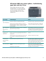
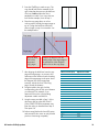
o
HP LaserJet printer product update
March 2005 • Volume 29
hp
It is now springtime, and business and support activities are picking
up! Customers are accepting the new strategies we have been
working on over the last few years, and are responding positively to
our new color and multi-function products.
New support and repair details for our introductory fall products are
available in this newsletter. We are sure you will find this information
invaluable! Please keep up the GREAT support.
Inside . . .
HP LaserJet 2400 series printer updates—troubleshooting paper jams and tray 2 issues.................... 2
HP LaserJet 4250/4350 series printer updates ............................................................................. 3
Fuser drive gears slip and grind .............................................................................................. 3
Print quality defects when printing envelopes ............................................................................ 4
HP LaserJet 4345mfp updates..................................................................................................... 5
Troubleshooting CHECK CABLES, CHECK SCANNER LOCK error message ................................. 5
Troubleshooting INITIALIZING SCANNER error message ........................................................... 7
Troubleshooting scan and copy print quality defects .................................................................. 9
Troubleshooting noise from the fusing assembly area ............................................................... 11
Troubleshooting CARD SLOT NOT INITIALIZED error message.................................................. 12
New firmware for the HP LaserJet 4345mfp............................................................................ 12
HP Color LaserJet 4600/4650/5500/5550 series printer updates .............................................. 13
Electro-Static Transfer Belt (ETB) cleaning cycle changes ........................................................... 13
Print quality optimization settings........................................................................................... 14
Print quality setting descriptions ............................................................................................. 15
How to recognize if a Download and Stay Resident (DLSR) color table is loaded ........................ 16
How to get temperature and humidity readings ....................................................................... 16
Troubleshooting CARDSLOT NOT INITIALIZED/49.4401 error messages................................... 18
Request for help in finding squeaky tray 2 problems ................................................................ 18
HP LaserJet 8100/8150 and 8150mfps—clearing a FUSER LOW TEMPERATURE message ............ 18
HP LaserJet 9040/9050mfps and HP Color LaserJet 9500mfp issues ............................................ 19
Troubleshooting OUTPUT DEVICE DISCONNECTED error message........................................... 19
Troubleshooting CHECK CABLES, CYCLE POWER error message.............................................. 19
Copy processor board EIO part issues ................................................................................... 19
New firmware for the HP Color LaserJet 9500mfp ................................................................... 20
HP Color LaserJet 9850mfp—cyan and/or magenta lines appear on color copies.......................... 22
HP Digital Sending Software (HP DSS 4.0) integration with FileNet............................................... 23
HP Restricted
HP LaserJet 2400 series printer updates—troubleshooting
paper jams and tray 2 issues
Some customers may report various paper
handling problems—for instance, paper jams,
no picks, or tray issues. Many of the problems
occur with units right out of the box. The
following table updates the issues we have
identified so far.
HP LaserJet 2420 printer
Error messages
Troubleshooting tips
Solution
13.01 Paper jam
or
Tray 2 Open/Empty
Check the pick-roller. Does it roll freely? If so, either the
pick-roller or the pick-up assembly shaft is broken.
If DOA, replace the unit.
If more than 30 days, replace the pick-up assembly.
Check the pick-up assembly paper flag. Is it broken or
stuck? Does toggling it trigger a control panel message? If
the paper flag sticks or is broken, the pick-up assembly
may be damaged.
Cause: Broken pick-up mechanisms, probably due
to removal of cardboard inserts during installation.
Tray 2 Open/Empty
or
Doesn’t pull from
Tray 2
Check the paper level indicator on tray 2, as it may have
slipped above the paper lift plate.
While holding the front of the tray in the left hand
and the rear of the tray in the right hand, twist the
tray slightly to allow the paper-level indicator to fall
back into place, clipping onto the paper lift plate.
13.20 error
message, but no
media found
Check the fuser delivery sensor. Is it stuck, missing, or
broken? Is the tension spring dislodged? Does the sensor
“spring-back”?
Fuser sensor: Replace the unit (if DOA) or replace
the fuser.
Check the paper access plate (duplex pan) and reseat it if
it is not hinged or seated properly (specifically the rear
hinges).
Duplex pan: Reseat the rear hinges.
Check the transfer roller. Reseat if necessary.
Use a letter opener to release the rear clip, and a
fingernail to release the front clip. Verify that the
spring is still attached to the transfer roller clip, and
there is space between the gear and the clip on the
left end of the transfer roller when inserting.
Cardboard inserts may be preventing the tray from
opening.
From the rear of the printer, compress and remove
the tray inserts, or push the duplex pan up far
enough to remove the tray. If necessary, remove the
rear guide to access the obstruction.
13.20 Paper jam
Paper found under
cartridge
Tray 2 will not open
The duplex pan may have fallen.
HP LaserJet 2400 series printer updates—troubleshooting paper jams and tray 2 issues
2
HP LaserJet 4250/4350 series printer updates
Fuser drive gears slip and grind
A grinding sound coming from the rear of some
HP LaserJet 4250/4350 series printers has
been noted. The sound disappears if the left
(gear) side of the fuser is pushed in while the
engine is printing.
Solution
Manufacturing has implemented the first of two
countermeasures to correct this problem. The
first countermeasure consists of adding an
alignment tool in the manufacturing process
which places the fuser cross-member in the
correct position. A second countermeasure is
forthcoming and will change the design of the
fuser drive gear so that it does not depend on
the placement of the fixing cross-member.
Series numbers for the first countermeasure
110V
220V
CNBXB 40880
CNBXC 50806
CNBXD 29918
CNBXF 15940
CNBXG 11558
CNBXH 4760
CNBXJ 913 26040
CNCXB 26040
CNCXC 25388
CNCXD 44977
CNCXF 50897
CNCXG 35087
CNCXH 4540
CNCXJ 565
HP LaserJet 4350n printer
Workaround
The following workaround procedure allows the
fuser drive gear to drop to a lower position,
increasing its engagement with the fuser.
1. Remove the left cover, following the
procedures in the service manual. This will
expose the three screws shown in the
photograph below. Loosen, but do not
remove these three screws.
Loosen the three screws indicated
HP LaserJet 4250/4350 series printer updates
3
2. Remove the formatter cover and formatter,
following the procedure described in the
service manual. This will expose the three
screws that hold the fuser cross-member on
the formatter side (see the photograph
below). Loosen, but do not remove these
three screws.
Print quality defects when printing
envelopes
Toner defects have been noted when printing
on heavy or textured envelopes. This rough
envelope media is usually outside of the printer
engine specifications, and is not supported as a
media solution for this printer family.
Workaround
1. Switch the fuser mode to High 1. This should
improve the print quality. (Go to Configure
Device, click Print Quality, click Fuser
Modes, click Plain, then click HIGH 1.)
OR
Loosen the three screws indicated
3. Rotate the fuser cross-member by pulling it
toward you and rotating the rear (inside) of
the cross member down. This will place all
six screws in the lower inside position of
their openings (see the photo below).
Rotate the fuser cross member
4. Re-tighten the six screws.
2. Switch the envelope printing option to
Rough. (In Microsoft® Windows®, click
Tools, click Letters and Mailings, click
Envelopes and Labels, click Options, then
select the Printing Options tab. From the
Feed from drop-down menu, click Rough.)
This setting will automatically change the
printer’s fuser mode setting to HIGH 1.
Switching the envelope option to Rough should
substantially improve print quality. If the
customer prints envelopes from tray 1, they can
also set the tray 1 Type to Rough (Go to Paper
Handling, click Tray 1 Type, then click Rough)
and couple it with the Microsoft Word
application setting of Rough. This will ensure
that all media fed from tray 1 will be in Rough
mode.
Workaround number 2 might be the best
approach, since workaround number 1 will
keep the fuser mode HIGH 1 setting for all other
medias from all other trays.
5. Install the formatter.
6. Replace the covers.
7. Test the printer by printing several test
pages to see if the fuser drive gear’s
slipping problem has been corrected.
8. If the fuser drive gear still slips, replace the
fuser and repeat the printing test.
9. If the fuser drive gear still slips, the engine
must be replaced.
HP LaserJet 4250/4350 series printer updates
4
HP LaserJet 4345mfp updates
Troubleshooting CHECK CABLES,
CHECK SCANNER LOCK error
message
A CHECK CABLES, CHECK SCANNER LOCK
error message may occur on the HP LaserJet
4345mfp. For troubleshooting purposes, it is
important to understand the different causes of
this message, which is usually a result of one
of the following issues:
•
The optical head in the scanner module is
unable to locate the home position within a
specified period of time.
•
The formatter PCA is unable to communicate
with the scanner module through the copy
processor board.
Optical head unable to locate home
position
If the optical head in the scanner module is
unable to locate the home position within a
specified period of time, troubleshoot the
following potential causes:
Scanner lock is NOT unlocked
Locking tab on
the optical
head
Ensure the scanner lock is unlocked. With early
MFPs, the locks required more force than one
would expect to unlock. Ensure the lock
mechanism is not binding (see the photo
below).
Optical head assembly is off the drive belt
A drive belt runs from the flatbed drive motor
to an idler pulley and through the optical head
assembly. If the drive belt has come off (usually
from the optical head assembly) no motion will
occur.
Scratches or dents in the guide rail
Since the carriage guide loop slides along the
guide rail, any dents or scratches on the guide
rail will contribute to erratic movement. This
defect typically results in intermittent CHECK
CABLES, CHECK SCANNER LOCK type
messages.
Excess weight or pressure on the flatbed glass
If too much weight or pressure is placed on the
glass, it could cause the glass to flex enough to
interfere with the movement of the optical
head. This has occurred when someone has
placed a book on the surface of the glass and
pressed down too hard on the ADF cover (for
example, with more than 33 pounds of
pressure).
Carriage guide loop is broken
Inspect the carriage guide loop. There have
been situations in which the product received
so much shipping damage that the guide loop
had broken. The carriage guide loop is
indicated by the top arrow in the photo below.
The bottom arrow indicates the guide rail.
Scanner
locking
mechanism
(ensure it is
not binding)
Ensure the scanner lock is unlocked
Carriage guide loop and guide rail
HP LaserJet 4345mfp updates
5
Scanner module base is warped
There have been isolated cases in which the
scanner module base was warped. In many of
these situations, you could easily scan from the
ADF assembly (where the optical head only
moved an inch), but you could not perform a
flatbed scan (where the optical head must
move the full length of the carriage). In these
situations the scanner module had to be
removed and we found that a clip on the
underside of the module was out of position,
causing the base of the module to flex, thus
hindering movement. In the example below an
out of position electrostatic discharge clip
distorted the base of the scanner module.
The graphic below shows the scanner module
removed from the MFP. You are looking at the
underside (bottom) of the scanner module.
Formatter not able to communicate
with the scanner module
There may be many different causes for these
types of errors. All communication between
these assemblies travel over ribbon cable
connected to CN101 of the
scanner/controller PCA to the top connector on
the formatter cage assembly. (When you
remove the formatter cage from the MFP there
are two connectors on the front edge of the
assembly.) Ensure the cables are seated
securely on the scanner/controller PCA, as
shown in the graphic at the bottom of this
page.
The photo below shows the connectors on the
chassis of the MFP with the formatter assembly.
A ribbon cable runs from the top connector in
the photo to CN101 on the scanner/controller
PCA. Ensure this ribbon cable is securely
seated on the scanner/controller PCA. The
ribbon cable installed in CN109 of the
scanner/controller PCA goes directly to the
optical head. It should also be securely seated.
Scanner module removed from the MFP
When troubleshooting the CHECK CABLES,
CHECK SCANNER LOCK errors, closely
inspect the preceding items. Note if the MFP is
able to scan from both the (1) Flatbed and (2)
ADF position, or from both positions.
Enable scanner diagnostics. (Press MENU,
Scroll down and touch DIAGNOSTICS, scroll
down and touch SCANNER TESTS, scroll
down and touch FLATBED MOTOR.) Observe
the optical head as it travels along the guide.
Note whether it is traveling the length of the
guide in a smooth and uniform motion.
Connectors on the MFP chassis
To ADF
Flatbed
motor
Formatter PCA
Inverter
PCA
Power
supply
Not used
Optical head
assembly
Scanner fan
Cover closed switch / Home position sensor
HP LaserJet 4345mfp updates
6
The photo below shows the inside of the
formatter cage. Inside the cage are two PCAs.
The top PCA is the copy processor PCA; the
bottom PCA is the formatter PCA. Connecting
these two PCAs is a daughter card. Ensure the
daughter card is securely seated on both the
formatter and copy processor PCAs.
Symptoms
•
The product boots-up to READY and can
print normally.
•
The amber LED under the START key is
illuminated, indicating an error condition.
•
The SCANNER INITIALIZING, PLEASE WAIT
message appears when you open the
Automatic Document Feeder (ADF) lid.
•
There is no response when you press the
START key to make a copy, or a SCANNER
INITIALIZING, PLEASE WAIT message
appears.
Background
Arrow points to the daughter card
1. Ensure the daughter card is securely seated
inside the formatter cage.
2. Ensure the formatter cage is securely
seated into the chassis of the MFP.
3. Ensure the ribbon cables are securely
seated onto CN101 and CN109 of the
scanner/controller PCA. Ensure the ribbon
cables are NOT damaged.
4. Ensure that the heartbeats of both the
formatter PCA and Copy Processor PCA
are functioning.
5. If the errors persist, replace the formatter
assembly.
During a scan operation, the optical unit reads
data during an ADF scan operation or from a
flatbed scan operation. This data is carried
from the optical unit through a ribbon cable to
connector CN109 of the Scanner/Controller
PCA. The data leaves the Scanner Controller
PCA via connector CN101 and goes to the
upper connector on the formatter cage
assembly and is fed to the Copy Processor
board. The copy processor board in connected
to the formatter PCA via a daughter card. Any
break along this communications path could
result in an error.
Prior to troubleshooting, it is always advisable
to observe if the heartbeat LEDs are blinking
indicating the system is functioning normally.
See the photo below.
Copy
Processor
heartbeat
LED
Troubleshooting INITIALIZING
SCANNER error message
If the scanner’s optical unit is not sending data
to the formatter PCA, you may get a
continuous INITIALIZING SCANNER error
message. Alternatively, the product may
power-up with no error message, yet the
Amber LED below the START key is illuminated,
indicating an error condition.
Formatter
heartbeat
LED
Observe blinking LEDs
HP LaserJet 4345mfp updates
7
Troubleshooting
Verify that all connections are good. Follow the
steps below.
1. Inside the formatter cage are two PCAs.
The top PCA is the copy processor PCA;
the bottom PCA is the formatter PCA. A
daughter card connects the two PCAs.
Ensure the daughter card is securely seated
on both the formatter and copy processor
PCAs. See the photo below.
3. Ensure the ribbon cables are securely
connected to CN101 and CN109 of the
scanner/controller PCA.
To ADF
Flatbed
motor
Formatter PCA
Inverter
PCA
Not used
Power Optical head
supply
assembly
Scanner fan
Cover closed switch / Home position sensor
The photo below is of the base of the
scanner module (with the glass removed).
Arrow points to the daughter card
2. Ensure the formatter cage is securely
seated to the two connectors on the
chassis. The photo below shows the two
connectors on the chassis of the MFP.
When you install the formatter cage onto
the MFP, the two connectors on the
formatter match up with these connectors.
The top connector shown in the photo
below connects into the copy processor
board inside the formatter cage. A ribbon
cable from this top connector goes to the
CN101 of the scanner controller PCA. The
scanner’s optical unit is connected by a
ribbon cable to CN109 on the scanner
controller PCA.
Optical unit
Ribbon cable
connects to
CN109 on the
scanner/
controller PCA
The base of the scanner module
4. Ensure the ribbon cable on the optical unit
is securely connected, and not damaged.
5. If the problem still persists after all the
connections have been verified, replace
the optical unit. There have been situations
in which excessive shock during shipment
misaligns the optical mirror within the
optical unit.
Connectors on the MFP chassis
HP LaserJet 4345mfp updates
8
Troubleshooting scan and copy
print quality defects
There have been situations where the MFP
scans or copies acceptably from the flatbed
glass, but does not scan or copy with
acceptable print quality from the ADF assembly
(please see the print quality defect examples
below). These defects are due to a
misalignment of the optical head. Use the
procedure in the next column to re-calibrate the
ADF scanning parameter.
Materials Needed
•
Target page (see the last page of this HP
LaserJet printer product update newsletter for
the target page).
•
Metric ruler.
•
HP LaserJet 4345mfp.
Procedure
1. Verify current setting as follows:
–
–
–
–
–
–
Press the MENU key.
Scroll and touch SERVICE. Enter the
service PIN (11434504).
Scroll to and touch SCANNER SETTINGS.
Scroll to and touch GLASS SETTING.
Touch ADF/GLASS SCAN START
POSITION.
Record the value in the field; press OK
and then EXIT.
2. Print a target page. Cut off the top portion
as indicated on the page.
Target page
3. After the top portion has been cut off,
place the target page on the flatbed glass
of the HP LaserJet 4345mfp. Place the
target face-down, with the cut edge
oriented to your left (as you face the MFP).
Ensure the paper is aligned squarely on the
flatbed, and the corner of the page is next
to the green home-position triangle on the
flatbed.
4. Place any paper in the ADF input guide to
ensure the ADF Paper Present indicator is
illuminated.
Examples of print quality defects
HP LaserJet 4345mfp updates
9
5. Press the START key to make a copy. The
copy should look like the example on the
right. Note that there are two parallel lines.
One line is bold and the other line is
standard line width. If your copy does not
look like the example, return to step 3.
6. Place the copy page down on a firm
working surface and lay the target page on
top of it. Align the bold lines from each
sheet of paper on top of one another. See
the example below.
Copy page
Copy page
Target page
Align the bold
lines of the
target and
copy pages.
Measure the distance from the
leading edge of the target page to
the intersection of the diagonal
and thin line on the copy page.
7. After aligning the bold lines from the copy
page and target page, use a metric ruler
and measure the distance from the leading
edge of the target page to the point where
the diagonal line of the target page
intersects with the fine line of the copy
page. Record this distance.
8. Using the table to the right, find the
corresponding value for the unit of distance
you measured. For example, if you
measured 20 mm, the corresponding
adjustment number would be 36.
9. Using the steps provided in Step 1 of this
document, and go to the ADF/GLASS
SCAN START POSITION parameter entry.
Enter the value you obtained from Step 8.
Then press OK.
10. Perform some black and white ADF copies,
and some ADF color scans to verify that the
product is functioning acceptably.
HP LaserJet 4345mfp updates
Measured value (mm)
Adjustment number
16.5
17
17.5
18
18.5
19
19.5
20
20.5
21
21.5
22
22.5
23
23.5
24
24.5
25
25.5
26
26.5
72
72
72
72
72
60
48
36
24
12
0
244
232
220
208
196
184
184
184
184
184
10
Troubleshooting noise from the
fusing assembly area
The MFP’s fusing assembly plugs directly into a
connector mounted on the product engine
power supply. There have been situations in
which the engine power supply appears to
have shifted downward during product
shipment. Even the most minimal downward
shift (1 to 2 mm) prevents the fusing assembly’s
drive gears from meshing properly with the
drive gears on the MFP’s chassis.
The photo below shows the engine power
supply positioned correctly, ensuring the
fusing assembly’s drive gears mesh
properly with the drive gears on the MFP’s
chassis.
Troubleshooting
If a grinding noise is coming from the fuser
area of your HP 4345mfp perform the
following:
1. Inspect the fusing assembly. Verify that the
gears are not excessively worn, the fuser is
seated properly into the chassis of the MFP,
and both latches are secure. Re-seat the
fusing assembly if necessary. Verify the
latches are not broken. If the latches are
broken, replace the fusing assembly and
return the broken fuser to the division for
analysis.
2. If the noise persists, remove the fusing
assembly and inspect the engine power
supply. In the photos below and top right,
a white ruler rests on the top of the engine
power supply. Notice in the photo below
that although slight, the engine power
supply has slipped down approximately
one millimeter.
The engine power supply in the correct
position
3. If the engine power supply has slipped,
you will need to reseat it. Remove the
fusing assembly, output bin, back cover,
DC controller shield, and the Power-FactorCorrection (PFC) power supply. Refer to the
service manual for instructions. Loosen the
three screws that secure the engine power
supply (see the photo below). Re-seat the
engine power supply (push it up as far as it
will go with the screws loosened) and then
re-tighten the screws.
The three screws that secure the engine
power supply
The engine power supply has slipped down
HP LaserJet 4345mfp updates
11
Troubleshooting CARD SLOT NOT
INITIALIZED error message
New firmware for the HP LaserJet
4345mfp
The error message CARD SLOT NOT
INITIALIZED may display on the HP LaserJet
4345mfp control panel. Investigation is under
way as to the root cause. Perform a disk
initializing (Disk Init) procedure as a
workaround to eliminate the error message.
Follow the steps below:
The new firmware revision 20050125
09.011.5 is now available at
www.hp.com/go/lj4345mfp_firmware
1. Power the MFP off, then on.
Note
This release incorporates all fixes previously
provided with 09.005.0, and is the supported
firmware for use with HP AutoStore.
2. During the memory count, press and hold
the right-hand side of the START key (the
big green key).
This new release includes new firmware for the
following devices:
• Stapler/Stacker accessory (Q5691A)
3. Hold the key until all three status LEDs are
illuminated.
•
3-Bin Mailbox accessory (Q5692A)
•
Scanner/controller PCA (Corrected the
situation where the premature ADF Output
Bin Full messages occurred.)
•
HP Embedded Jetdirect
4. Press the number 5 key until INITIALIZE
DISK displays.
5. Press the number 6 key one time and allow
the MFP to boot-up.
If performing a disk initialization procedure
does not clear the error, it may be necessary to
replace the flash memory card, part number
Q2635-67907.
Firmware revisions for all devices included in
this firmware bundle are listed in the table
below:
Device
Firmware revision
LaserJet 4345mfp series
printer
09.011.5
3 Bin mailbox
(Q5692A)
MP02.26
HP Stapler/Stacker
(Q5691A)
MP02.27
Analog Fax Accessory
(Q3701A)
2.32s
HP Embedded Jetdirect
V.28.47.FF
Copy processor board
0.190 (2.0)
Scanner/Controller PCA
26
For a detailed list of all improvements and
corrections included in this revision, please see
the readme file that comes with the firmware.
HP LaserJet 4345mfp updates
12
HP Color LaserJet 4600/4650/5500/5550 series printer
updates
Electro-Static Transfer Belt (ETB)
cleaning cycle changes
The ETB cleaning cycles in the HP Color LaserJet
4600/4650/5500/5550 series printers have
changed to reduce the risk for the following two
defects:
•
ETB streaks
•
Cleaning blade streaks
Normally an ETB cleaning cycle is performed at
the following times:
•
After every job printed from tray 1, when tray
1 is set to Any Paper Size/Any Paper Type
•
After every 90 pages of printing
•
After every calibration cycle
•
After opening and closing the top cover
(Checking Printer)
HP Color LaserJet 4650b printer
Side effects
To accommodate these customers, we have
implemented a switch in the control panel menu
that will turn the cleaning cycle on after a job
from tray 1. This option can be found under
CONFIGURE DEVICE/PRINT
QUALITY/OPTIMIZE/TRAY 1. The default
setting is AUTO 1 (which means a cleaning
cycle is not performed after every job printed
from tray 1, when tray 1 is set to Any Paper
Size/Any Paper Type). By setting the mode to
AUTO 2 the cleaning cycle is turned on again.
Accidental
Note
Toner transfers from the ETB to the media if the
orientation of the paper does not match the
default orientation when using the tray 1
setting, Any Paper Size/Any Paper Type. For
example, if the customer uses letter size paper
in Short Edge or Letter Rotated orientation, and
tries to print a configuration page, toner will be
transferred to the ETB, and then be deposited
on the back side of subsequent long edge fed
sheets. The default orientation is Long Edge.
The customer should only be instructed to use
the AUTO 2 setting in the Intentional case.
The ETB cleaning cycle is no longer performed
after every job printed from tray 1, when tray 1
is set to Any Paper Size/Any Paper Type. The
elimination of this cleaning cycle will help
eliminate ETB streaks and cleaning blade
streaks.
Intentional
If a customer purposely prints off the page, for
example, to print edge-to-edge on a slightly
smaller paper size, then toner will be
transferred to the ETB and will be deposited on
the backside of subsequent pages.
HP Color LaserJet 4600/4650/5500/5550 series printer updates
13
Print quality optimization settings
Adjust print quality settings
Overview
All optimization settings appear under the
CONFIGURE DEVICE menu. To access these
settings:
For most jobs on most media, the printer’s
default settings provide the best combination of
print quality and print speed. However, if you
experience print quality problems caused by
extreme environmental conditions (such as low
humidity or high temperature) or media type
(such as glossy or tough) or the use of special
media, you can optimize print quality settings
from the printer’s control panel.
Adjust print mode settings
In addition to normal print modes, you can
access print modes that apply to a single media
type. For example, if you wish to print a
transparency, you might choose
HUMID/TOUGH MODE or HUMID/OHT
MODE from a list of all of the print modes,
following the steps below:
1. Press MENU.
2. Press down () to highlight CONFIGURE
DEVICE and press select (D).
3. Press down () to highlight PRINT QUALITY
and press select (D).
4. Press down () to highlight PRINT MODE
and press select (D).
5. Press down () to highlight
HUMID/TOUGH MODE or HUMID/OHT
MODE and press select (D).
The table below depicts the print modes in the
left column as they appear in the control panel.
The right column identifies the corresponding
video interface command for the HP Color
LaserJet 4650 or 5500 series printer.
Print quality
mode
Video interface command
HUMID/TOUGH
MODE
HUMID/OHT
MODE
EEC94 bit 10—Listed as “high
humidity gloss film designation”
EEC94 bit 11—Listed as “high
humidity OHT designation.”
1. Press MENU.
2. Press down () to highlight CONFIGURE
DEVICE and press select (D).
3. Press down () to highlight PRINT QUALITY
and press select (D).
4. Press down () to highlight OPTIMIZE and
press select (D).
5. Press down () to highlight one of the
following fields:
–
–
–
–
–
REDUCE BACKGROUND
TRANSFER
OHT FLATNESS
FUSER ACOUSTIC NOISE
HOT OFFSET
6. Press select (D).
7. Press down () to highlight one of the
following fields (not all fields will be
available):
–
–
–
–
–
NORMAL
INCREASED
BEST
LIGHT
MIXED MEDIA
8. Press select (D).
The table below depicts the optimization modes
in the left column as they appear in the control
panel. The right column identifies the
corresponding video interface command.
Print quality
mode
Video interface command
REDUCE
BACKGROUND
EEC96 bit 14—Background Gray
Prevention Designation 1 (same as CLJ
4600)
EEC98 bit 11—OHT Flatness Priority
Designation (new for CLJ 4650/5500)
EEC98 bit 12—Fuser Noise Reduction
Designation (new for CLJ 4650/5500)
OHT FLATNESS
FUSER
ACOUSTIC
NOISE
HOT OFFSET
TRANSFER
N/A
HP Color LaserJet 4600/4650/5500/5550 series printer updates
EEC96 bit 10—Hot Offset Improvement
Mode (new for CLJ 4650/5500)
EEC96 bit 15—High resistive Paper
Designation (same as CLJ 4600)
EEC94 bit 15—This command is not
used for the CLJ 4650 printer.
14
Print quality setting descriptions
Transparency flatness
Reduce background
Adjusting the overhead transparency flatness
setting (OHT FLATNESS for the 4650, and
TRANSPARENCY for the 5500) increases print
speed from one-third to half engine speed to
minimize waviness. However, this setting may
result in reduced print quality in the form of
reduced image brightness when projected.
HP recommends this print mode only for
customers who are very sensitive to waviness.
Overhead transparency waviness has no
impact on the quality of the projected
transparency.
Background (stray toner) may appear when
printing on glossy or tough media. Adjusting
the REDUCE BACKGROUND setting may help
reduce background. However, if the
background is severe, this method may not be
sufficient to restore print quality to an
acceptable level.
How does it work?
When REDUCE BACKGROUND is set to LIGHT,
the developer bias voltage is reduced by -50
volts. This reduces the voltage difference
between the background area of the
photoconductor (~625 volts) and the developer
bias (~325 volts) from 300 to 250 volts. This
countermeasure assumes that the background
problem is due to the presence of wrong-signed
toner (positive toner) in the developer. The 250
volt difference develops less positive toner in the
background areas.
In addition to adjusting voltage, the glossy
mode print speed increases from one-third to
half engine speed. The increased print speed
reduces background by limiting background
particle spread during fusing. This results in a
reduction of the overall glossiness of the image.
Transfer
Although the printer is designed to
accommodate all supported media types,
adjusting the TRANSFER setting may resolve
transfer problems such as missing toner on a
printed page or print quality defects observed
only on the second side of a duplexed page.
These defects typically occur if the media type
has unusually high resistivity (such as extremely
rough media or media in Asian markets) or if
the ambient room humidity is known to be low.
How does it work?
The transfer voltage for each color is reduced
by 250 volts when printing the second side of a
duplexed job. This voltage reduction minimizes
the possibility of electrical discharge marks
during transfer. (When printing in Duplex
mode, the side facing down in the output tray is
the second printed side.)
HP Color LaserJet 4600/4650/5500/5550 series printer updates
Fuser acoustic noise/fuser warm up
Adjusting the FUSER ACOUSTIC NOISE (for the
4650) or FUSER WARM UP (for the 5500)
setting will eliminate a high-pitched ringing from
fuser vibration with some printers in certain
environments. The method used to heat the fuser
can instigate resonance that creates a highpitched sound audible to some people. The
solution slightly slows the heating process to
avoid exciting this resonance, and as a result,
customers may experience a slight reduction in
first-page-out times.
Hot offset/media type
Adjusting the HOT OFFSET (for the 4650) or
MEDIA TYPE (for the 5500) setting will
eliminate a possible ghosting or repeated
pattern on glossy media types under certain
conditions, which often include a hightemperature environment. The print problems
may occur if 20 or more pages are printed in
normal mode and then a page is immediately
printed in glossy mode (including
transparencies). In this situation, the fuser may
not cool sufficiently before printing the glossy
page. This may cause toner to stick to the fuser
and appear as a faded, repeated image
starting about four inches down the page.
Adjusting the HOT OFFSET/MEDIA TYPE setting
increases the wait time to ensure that the fuser
is at the proper temperature. The additional
time will range from a few seconds to three
minutes. The control panel will continue to
display the normal PROCESSING PAGE
message.
15
How to recognize if a Download
and Stay Resident (DLSR) color
table is loaded
Download and Stay Resident (DLSR) color
tables may be copied to HP Color LaserJet
4650, 5550, 9500hdn and 9500mfp
products, providing customers with custom color
tables to match their company colors, or to
emulate another HP printer or a competitive
printer model.
Note
The HP Color LaserJet 9500hdn requires
05.005.3 or later firmware.
How does it work?
The DLSR color table is a small file which the
customer can copy to the file system of their
printer to create a new color directory. (For
example, 0:\colorTable.) Copy this file the
same way you would send an rfu file. After the
file is sent, the printer reboots and the new
color tables go into effect.
To determine if a DLSR table is active on the
printer, it is necessary to print a File Directory
from the INFORMATION MENU. If there are
any files present in the 0:\colorTable directory,
the printer is using a DLSR color table.
The base set of color tables can be used again
if you delete the DLSR color table.
Flashing the firmware to an older or newer
version will not remove the DLSR color table.
This is one reason why using DLSR is a great
solution for customers that need to upgrade
firmware in the future and not worry about
losing their custom color tables.
Note
DLSR color tables will be built on an escalation
basis only.
How to get temperature and
humidity readings
The HP Color LaserJet 4650 and 5550 series
printers have a built in temperature and
humidity sensor. This sensor adjusts the printing
system, improving the printer’s color
consistency. The temperature and humidity
values are reported on the configuration page.
Finding temperature and humidity
values
The temperature and humidity values are
hidden in the block of numbers on the bottomright of the configuration page. See the graphic
on the next page.
Each printer has multiple color tables in which
the new custom color table can override, for
example, RGB, CMYK, Vivid, or Swop. The
new DLSR tables will not delete the older tables,
but will override them. When the printer is
turned on, the initialization process will look for
any color table in the new directory. If one is
found, the color table in the base firmware will
be ignored.
HP Color LaserJet 4600/4650/5500/5550 series printer updates
16
Configuration page
Three of the numbers on this page relate to
temperature and humidity:
1. The number circled in red at position M6 is
the temperature measured at the last
calibration cycle. The value is in
Hexadecimal format. Convert this number
from Hexadecimal to Decimal and the
Decimal value is the temperature in degrees
C. So in this case 19 in Hexadecimal is 25
Decimal, so this printer calibrated while it
was 25 degrees C. The printer is operating
within specifications if the temperature is
between 15 and 25 degrees C.
2. The number circled in orange at position L7
is the real time temperature (HP Color
LaserJet 5550 only). The value is in
Hexadecimal format. Convert this number
from Hexadecimal to Decimal and the
Decimal value is the temperature in degrees
C. So in this case 18 in Hex is 24 Decimal,
so when this Configuration page was
printed the environment was 25 degrees C.
The printer is operating within specifications
if the temperature is between 15 and 25
degrees.
HP Color LaserJet 4600/4650/5500/5550 series printer updates
3. The number circled in blue at position N6 is
the Relative Humidity. To look up the
approximate Relative Humidity, use the
table below. If the Relative Humidity is less
than 20% or more than 80% the customer is
printing in an unsupported environment. If
the number is not in the table, as in our
case of 3C for example, the Relative
Humidity is simply between the two closest
values. (In this case, between 3B and 4A.)
So 3C means the Relative Humidity is
between 20 and 25%.
N6 value (Hex)
14
29
3B
4A
56
5F
67
6E
75
7A
80
84
88
8C
90
94
98
% RH
10
15
20
25
30
35
40
45
50
55
60
65
70
75
80
85
90
17
Troubleshooting CARDSLOT NOT
INITIALIZED/49.4401 error
messages
A customer may receive one of the two
following error messages:
•
CARDSLOT NOT INITIALIZED
•
49.44 01 SERVICE ERROR
Both of these errors indicate that the user space
on the CompactFlash card is corrupted.
Solution
To resolve this issue it is necessary to perform a
Disk Init procedure.
Note
If a hard drive is installed in the printer, remove
the hard drive before executing the Disk Init
procedure, ensuring that all stored jobs are
preserved.
Disk Init procedure
1. Turn the printer off, then on.
2. When the memory count starts on the
control panel, press and hold the MENU
button until all three lights on the control
panel are lit.
3. Press the < button. The message INITIALIZE
DISK appears in the display.
4. Press the Check button. The printer will
initialize the user space on the
CompactFlash card and will continue its
power-on sequence.
Request for help in finding
squeaky tray 2 problems
The division is aware of an emerging issue with
the HP Color LaserJet 4650 series printer. An
unidentified squeak comes from the tray 2 area
of the printer.
The squeak starts as a very soft squeak, but gets
louder when the printer warms up or prints long
jobs. In our initial investigation we have found
that the squeak is very noticeable after
approximately 50 pages of continuous printing.
The squeaking occurs when printing from the
tray 2 area of the printer.
Solution
At this time, the only solution is to replace tray
2.
Feedback requested
Please send the defective trays to the following
address:
Hewlett-Packard Company
Attn : Frankwin Hooglander
11311 Chinden Blvd / MS327
Boise, ID 83714
Include the following information when you
return the trays:
•
Name
•
Case ID number
•
Contact information (address and telephone
number
HP LaserJet 8100/8150 and 8150mfps—clearing a FUSER
LOW TEMPERATURE message
HP has noted an increase of 50.1 FUSER LOW
TEMPERATURE error message issues. Our
evaluations show that most of the returned
fusers are not defective.
We have found that removing or replacing the
fuser assembly with the power ON to the printer
can prompt a 50.1 FUSER LOW TEMPERATURE
error.
HP Color LaserJet 4600/4650/5500/5550 series printer update
Solution
To clear a 50.1 FUSER LOW TEMPERATURE
error, turn the power off, reseat the fuser, wait
2 to 3 minutes to reset, then turn the printer
back on.
18
HP LaserJet 9040/9050mfps and HP Color LaserJet
9500mfp issues
Troubleshooting OUTPUT DEVICE
DISCONNECTED error message
HP has received calls about 65.12.99 OUTPUT
DEVICE DISCONNECTED error messages on
the HP LaserJet 9040/9050mfps. The error
appears to be related to how the printer and
output device wake up from PowerSave. We
have seen a few cases where the output device
was not fully attached to the engine or where
the JetLink connector was not fully seated.
1. Check all hardware connections first.
2. Turn off PowerSave. The lab is working on
a firmware change.
Troubleshooting CHECK CABLES,
CYCLE POWER error message
A CHECK CABLES, CYCLE POWER message
may be due to improper insertion of the
memory DIMM. It may appear to be seated
firmly into the connector, however, if you are
experiencing intermittent failures or a hard
failure, the DIMM may not be properly seated.
Reseating the DIMM
Insert the DIMM into the socket and push down
until the retention device is activated (often
sensed by an audible or tactile ‘click’). When
rotating the DIMM down into the locking
position, be sure to push into the socket, or the
DIMM may move out of the socket even though
it “clicked” in place.
The photo below shows a DIMM completely
inserted into the socket. Note the copper
contact exposed along the connector edge.
HP LaserJet 9050mfp
Copy processor board EIO part
issues
The copy processor board EIO (part number
Q2679-67901) was originally intended to
work on all three products—the HP LaserJet
9040mfp, the HP LaserJet 9050mfp and the
HP Color LaserJet 9500mfp. However, the
memory DIMM was not added to the part. We
also determined that the HP Color LaserJet
9500mfp used 512 MB of memory instead of
256 MB.
Temporary workaround
Move the memory DIMM from the failing copy
processor board EIO to a new copy processor
board.
•
We will be setting up another part number for
the HP Color LaserJet 9500mfp copy
processor board with 512 MB of memory.
•
We will add 256 MB of memory to the
existing copy processor board for the
HP LaserJet 9040mfp and the HP LaserJet
9050mfp.
Memory DIMM correctly seated
HP LaserJet 9040/9050mfps and HP Color LaserJet 9500mfp issues
19
New firmware for the HP Color
LaserJet 9500mfp
The following issues have been resolved with
the revision 08.011.5 firmware roll, now
available at the following URL:
www.hp.com/go/lj9500mfp_firmware
Note
This release incorporates all fixes previously
provided with 08.005.0, and is the official
support firmware for use with HP AutoStore.
HP Color LaserJet 9500mfp
•
When email is configured, but not connected,
the message is now “Not Available” instead
of “Not Configured”.
•
LDAP lookup would no longer function after
executing a Find Send Gateways without
network connectivity. An NVRAM INIT was
required to restore LDAP lookup functionality.
•
HP Web Jetadmin unable to complete a
remote firmware upgrade with the control
panel locked. This revision changes how
future upgrades will be handled, but
upgrading to this revision will still require a
manual reboot.
Resolved issues
You may see improvements for the issues below
by updating your printer’s firmware with
revision 20050105 08.011.5.
•
Truncated fax delivery emails in some
languages.
•
Under rare circumstances, SNMP status
reports Off-Line while the control panel reads
READY.
•
Processing Job hang on paper out when Input
Auto-Continue is set to No Timeout.
•
Security improvements implemented with MFP
is used with HP DSS 4.0 (HP Digital Sending
Software).
•
LDAP server hostname resolution only
happened at boot-up, rather than
dynamically.
•
Incorrect French localization of media sizes in
Copy Settings.
•
Fax that couldn’t print, caused by paper out
for example, was lost on power cycle.
•
Mixed letter and legal originals can now be
copied via the ADF.
•
Incorrect page counts in XML data.
•
Some output device configuration settings not
reflected in HP Embedded Web Server.
•
49.4C02 error when a null value is entered
for LDAP IP address.
•
ADF (Automatic Document Feeder) OUTPUT
BIN FULL was being triggered at the incorrect
number of pages.
•
Slow printing on certain jobs due to timing
issues.
•
Images are rotated 90 degrees when copying
small items from glass.
•
In some unique network environments, the
MFP sends multiple copies of the same email
message.
•
Pressing Reset in text entry mode results in a
blank menu.
•
Control panel may lock up when setting
custom paper sizes.
•
Fax country codes are added for Estonia,
Iceland, Japan, Latvia, Liechtenstein,
Lithuania, Morocco, and Slovenia.
•
Restore Factory Settings does not restore
Exclusive Tray settings.
•
EIO page is missing from printout when 3rdParty Configuration page is registered.
•
75 dpi emails are sent as 150 dpi.
•
The Fax Icon was not enabled on the HP DSS
4.0 machine after HP DSS 4.0 had been reinstalled.
HP LaserJet 9040/9050mfps and HP Color LaserJet 9500mfp issues
20
•
A Fax job would fail if the default resolution
was changed to Superfine after starting the
job.
Current firmware revisions for all devices
included in this firmware bundle are listed in the
table below:
•
Job Mode ON and Authentication ON
caused jobs to be canceled after inactivity
timeout.
Device
Firmware revision
•
Receive a 65.12.99 error when trying to
wake up the printer from HP Web Jetadmin.
LaserJet 9500MFP
Series Printers
08.011.5 (Datecode:
20050105 08.011.5)
2000 sheet input tray
(Q1891A)
0112
Stapler/Stacker
(C8085A)
040819
Stacker (C8084A)
040820
8-Bin Mailbox
(Q5693A)
040804
HP Multifunction
finisher “B” (C8088B)
040827
Copy processor board
0.188 (2.1)
Scanner Control
Board
MFP301 10
Fax Modem
2.32s
Enhancements provided with this firmware
revision
•
Exclusive tray settings now allow alternate
tray selection prompt to be disabled.
•
The Stop button can now be used to cancel a
fax.
•
The sender of an email can automatically be
copied on all messages. A configuration file,
available from HP support, enables this
behavior.
•
Device POP3 username size limit increased
from 16 characters to 256 characters.
•
Manual copy settings show two paper sizes
selected when copying Letter-R or A4-R.
•
Improvements were made in how the MFP
handles control panel messages from thirdparty solutions.
•
Simplex landscape images are rotated 180
degrees on any n-up copy job.
The following devices were NOT updated with
this firmware revision:
•
HP Multifunction finisher
•
Stapler/Stacker
•
Stacker
•
8-Bin Mailbox
•
2000 sheet input tray
HP LaserJet 9040/9050mfps and HP Color LaserJet 9500mfp issues
21
HP Color LaserJet 9850mfp—cyan and/or magenta lines
appear on color copies
For every new installation, you need to enter the
phone and fax number of the service office
where the customer will call for attention, as
well as the installation date. If this important
information is not entered, cyan and/or
magenta colored lines will appear in the
process direction every time a color copy is
made. See the sample pages below.
Solution
The lines will disappear when the installation
date, phone, and fax number are entered via
25 mode.
Leading edge
Cyan-colored
lines
Process direction
Magenta-colored
lines
HP Color LaserJet 9850mfp—cyan and/or magenta lines appear on color copies
22
HP Digital Sending Software (HP DSS 4.0) integration with
FileNet
This document provides an overview of how the
HP Digital Sending Software 4.0 (HP DSS 4.0)
integrates with the FileNet product.
The solution implements an integration of
HP DSS 4.0 with the FileNet system, allowing
MFPs and Digital Senders to become onramps
to FileNet’s document management system. This
document describes the simplest integration of
HP DSS 4.0 with FileNet that can occur,
utilizing Custom Keys to capture metadata and
route scanned documents to a shared folder
that is monitored by the FileNet system. The
document and metadata are imported into
FileNet using the Capture Professional
application, and further processed before being
committed into the FileNet repository.
How does it work?
HP DSS 4.0 can be configured to generate files
that are imported into FileNet Capture
Professional, with metadata automatically
assigned to index items appropriate for the
document class. Capture Professional can also
be used to do additional processing, such as
barcode/OCR, filtering, document splitting,
along with manual indexing, etc. Listed below
are important facts about how the integration
works.
1. To pass metadata the solution uses a file
with an .FNA file extension. The .FNA file is
a text file, with each metadata item on its
own line; no keywords, tags, or other
structures are used.
2. The creation of the “notify.dat” file, which
generally occurs whenever HP DSS 4.0
adds a new file to a directory, does not
occur when .FNA is chosen as the metadata
file format. It is removed because it confuses
the file import process of Capture
Professional, which expects to find only a
valid image and metadata file in the
directory. Capture Professional uses its own
method for detecting whether new files exist
in the directory.
HP Digital Sending Software (HP DSS 4.0) integration with FileNet
HP 9200c Digital Sender with HP Digital
Sending Software 4.0
3. HP DSS 4.0 creates additional built-in
metadata items, (also known as hidden
prompts) that an administrator can use in a
form. FileNet customers will be able to add
these items into the .FNA file. These items
are as follows:
•
HP DSS 4.0 Server Host Name
•
Form Path Name
•
Form Name
•
Windows NT® Authenticated username (NT
only)
•
NT Authenticated domain name (NT only)
•
NT Authenticated domain\username
(combines first two items) (NT only)
•
Novell Bindery server (Novell only)
•
Novell NDS Context (Novell only)
•
Novell NDS Tree (Novell only)
•
Authenticated user’s email address
(administrator’s email if GUEST)
•
MFP Name (IP address or hostname, as
configured in Config Utility)
•
Scan date (format according to control
panel’s Regional & Language Options)
•
Scan time (format according to control
panel’s Regional & Language Options)
•
Number of pages
•
Document file name root (e.g. s2d4555)
•
Document serial number (GUID)
23
•
File Path (FTP or network share only)
•
FTP Server name (FTP only)
Note
Because some items are inappropriate for
certain configurations, the configuration utility
will check for inappropriate selections when the
user clicks the Apply button for the
configuration. If it finds such a situation, it will
generate a warning, but will still allow the
configuration to be saved. If this occurs,
inappropriate prompt answers will be blank
when the job is processed.
4. To aid in document traceability, the
Document Serial Number is added to the
log entry of the document. This enables
FileNet customers to associate, with
absolute certainty, which documents were
created from a particular session of the MFP
and HP DSS 4.0.
The graphic below shows how data flows
within an HP DSS 4.0/FileNet integration. The
control panel screen shots shown on the next
page are from a sample configuration and will
vary dependent upon the specific
implementation used.
.FNA and image
files are stored in
Windows Share for
FileNet to retrieve
Pressing Start initiates job
HP DSS 4.0 then validates
metadata
FileNet imports files
and processes them
Configuring HP DSS 4.0 and FileNet for Integration
Follow the steps below to set up FileNet
Capture Professional with HP DSS 4.0 in order
to import documents from an MFP or Digital
Sender into FileNet.
FileNet content engine administrator
1. Create a new document class (if needed) to
represent the type of document to be
scanned. Select document properties for the
document class, which will be used to index
this type of document. The properties should
HP Digital Sending Software (HP DSS 4.0) integration with FileNet
include any items to be tracked with the
document, including any indexing
properties that that will be captured at the
control panel of the device, or provided by
HP DSS 4.0 as part of the standard built-in
metadata items (such as the authenticated
user’s name).
2. Create a folder that will contain the new
documents, or identify the location within
FileNet where documents should be
committed.
24
HP Digital Sending Software
1. Create a Windows Share Directory where
HP DSS 4.0 will drop documents. Capture
Professional will monitor this folder for such
documents. No other metadata forms
should share this directory, since all files
found in this directory are assumed to be of
the same document type.
3. Next, the newly created Windows Share
directory should be entered into the Folder
Path box as shown below.
2. Create a Custom Key Form for the above
document type by clicking Add Form (see
the screen capture below).
Add Form Configuration Tab
4. Next, create document metadata items. In
the Workflow Form window, select .FNA as
the File Format (see the Workflow Form
window above), and assemble a list of
indexing items, either to be prompted at the
control panel, or built-in metadata items
filled in by the HP DSS 4.0. To add
metadata items click Add.
DDS Configuration Utility
5. In the Add Prompts window (below) select
an item from the list and click Add. Click
New to create new metadata items.
Add Prompts Configuration Tab
HP Digital Sending Software (HP DSS 4.0) integration with FileNet
25
6. The configuration screen to add a new
metadata item is shown in the Workflow
Prompt window below. Once you have
added all the metadata indexing items
needed, click OK to store the list, click OK
to save the form, and finally, click Apply to
apply the changes to the service.
3. Select Auto Index, and check Process
documents using initial values above.
4. Select the Field tab.
5. Associate each prompt answer in the
sample document’s FNA file with the
metadata items in the new document class:
a. Select the document property to be
configured. Click Configure.
b. Select the Auto-Index tab field.
c. Select Source Group of User Defined.
d. Select from Value1 to Value32
depending upon which line item of the
.FNA file will contain the indexing data
for this property.
e. Click Append Auto Index String.
f.
New Prompt Configuration Tab
FileNet Capture Professional
1. Create a settings collection in Capture
Professional. This will allow the
configuration information to be stored and
used as a settings template for all users
importing this type of document.
2. Set document type to newly created
document class. (If New Document Class
does not appear in the drop down list,
make sure that the client was updated with
the server changes made above).
3. Configure import settings to look for
documents in the HP DSS 4.0 share created
in the previous step.
4. Turn on automatic import to capture the first
document.
At the MFP or Digital Sender
Select the new custom key created in the steps
under HP Digital Sending Software. Answer all
prompts, and scan a sample document (the
sample is used for future reference and is stored
in the FileNet system).
Return to FileNet Capture Professional
1. Stop the import step.
Repeat for each metadata item to be
auto-indexed.
6. Configure Commit settings to deposit the
document in the CE folder previously
created.
7. Create a template that uses the new settings
collection just created (contains the sample
document and all the configured settings).
8. Enable Automatic Import using the newly
created template.
Summary
The HP MFP Digital Sending Software can be
configured to integrate with FileNet. Once
integrated, HP DSS 4.0 creates a document
and an associated .FNA file that are placed in
a Windows Shared directory. FileNet Capture
Professional monitors this shared directory and
imports any new files that are placed within it.
Once FileNet imports the document and .FNA
file, it processes the files and places them in the
FileNet repository.
The above information is an example of
FileNet/HP DSS 4.0 integration and is not
intended as a complete description of all
possible ways to integrate FileNet with HP DSS
4.0. Please consult the documentation provided
with your FileNet system for more information.
2. Select Configure, then Index settings in the
settings collection.
HP Digital Sending Software (HP DSS 4.0) integration with FileNet
26
g
g
Microsoft, Windows NT, and Windows are U.S. registered trademarks of Microsoft Corporation.
© Copyright 2005 Hewlett-Packard Development Company, L.P. The information contained herein is subject to change without
notice. The only warranties for HP products and services are set forth in the express warranty statements accompanying such
products and services. Nothing herein should be construed as constituting an additional warranty. HP shall not be liable for
technical or editorial errors or omissions contained herein.