1
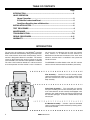
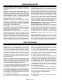
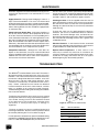
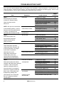
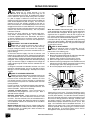
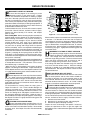
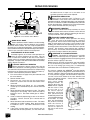
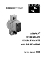
ROSS CONTROLS®
®
SERPAR
CROSSFLOW
DOUBLE VALVES
with E-P MONITOR
Service Manual
350D
TABLE OF CONTENTS
Page
INTRODUCTION..........................................................................................................2
VALVE OPERATION
Normal Operation...............................................................................................3
E-P Monitor Lockout and Reset.........................................................................4
Conditions Resulting from a Malfunction........................................................5
INSTALLATION NOTES...............................................................................................6
TEST PROCEDURE....................................................................................................6
MAINTENANCE...........................................................................................................7
TROUBLESHOOTING.............................................................................................7-8
REPAIR PROCEDURES.........................................................................................9-11
WARRANTY................................................................................................................12
INTRODUCTION
The two main valve elements in the SERPAR® Crossflow
double valve move simultaneously during normal operation.
If the valve elements fail to move simultaneously, the E-P
monitor is designed to detect this condition. The monitor
reacts by disconnecting the electrical supply to the pilot
valve solenoids, so that further valve operation is inhibited.
The valve is then said to be “locked out” and cannot return
to normal operation until the monitor is reset. A lockout is
not necessarily an indication that the valve has become
faulty. Rather, it is an indication that the monitor has
detected non-simultaneous movement of the main valve
elements, and that there is a condition in the system that
needs correction.
The SERPAR® Crossflow double valve with E-P monitor
consists of three interconnected assemblies (see below).
Pilot Assembly – Consists of two 3/2 normally closed,
solenoid controlled pilot valves in a single housing. Each
pilot valve controls one of the valve elements in the valve
body assembly.
Valve Body Assembly – The valve body has parallel
flow paths including two in-to-out crossflow paths. The two
main valve elements are 3/2 normally closed poppet valve
elements, plus spool elements that control air flow through
the crossflow passages. A silencer is bolted directly to the
exhaust port.
E-P Monitor Assembly – Contains a pressure controlled
spool, an electrical two-position momentary latching switch,
and a reset solenoid.
ROSS CONTROLS®
NORMAL VALVE OPERATION
Becoming thoroughly familiar with the functions of the
SERPAR® Crossflow double valve and its E-P monitor
will help in analyzing lockouts and finding their causes.
The next few pages should be studied carefully to get an
understanding of both the normal valve functioning and
what happens when a malfunction occurs.
F
F
B
CONDITIONS AT START
4
A
3
2
Inlet air is blocked from the outlet port by two normally
closed valve elements A and B (see Figure 1). The outlet
port 2 is connected to the exhaust port 3. Pilot supply air
comes from the inlet port 1, and is carried via passage
4 to the two 3/2 normally closed, solenoid controlled pilot
valves F.
1
SOLENOIDS ENERGIZED
Simultaneously energizing the two solenoids “a” and “b”
(Figure 2) causes the two pilot poppets E to shift. This
closes the pilot exhaust passages and opens the pilot
supply passages. Pilot air can then go to the main valve
pistons J via passages 5. Pressure on the pistons shifts the
main valve elements. This closes off the exhaust port 3, and
connects the inlet port 1 to the outlet port 2 via the crossflow
passages 10 and 11.
With the main valve inlet poppets U and V open, the
monitoring passages 6 are open to inlet pressure. This
pressure is directed to both ends of spool W. Because these
monitoring signal pressures are equal, spool W remains in
its center position. Note that the valve elements must move
simultaneously in order for the E-P spool to remain in its
pressure balanced center position.
Figure 1 – Solenoids Not Energized
b
a
E
5
E
5
J
J
3
2
SOLENOIDS DE-ENERGIZED
Simultaneously de-energizing solenoids “a” and “b” allows
the two pilot poppets E to return to their normally closed
positions. Pilot pressure on the main valve pistons J is
exhausted through exhaust port 3 via internal exhaust
passages (not shown). The main valve piston poppets J, and
inlet poppets U and V return to their normal de-actuated
positions. Inlet air is again blocked from outlet port 2
by poppets U and V. Pressure at outlet port 2, at the
ends of spool W, and in the monitoring passages 6 is
exhausted through exhaust port 3. This completes the
normal operating cycle, and the valve has returned to the
Conditions at Start described above.
1
11
V
6
6
10
U
W
Figure 2 – Solenoids Energized
www.rosscontrols.com
E-P MONITOR LOCKOUT AND RESET
C
K
W
M
T L
M
6
6
Figure 3 – Horizontal Cross Section of E-P Monitor
E-P MONITORING and LOCKOUT
the valve function) inlet pressure via passage 6 will be
applied to one end of the spool sooner than at the other
end. When the pressure differential exceeds 2 bar (30 psi)
the pressure imbalance causes the spool to shift, tripping
switch actuator pin K. This shifts switch L and breaks the
circuit to the pilot solenoids (see Figure 5 below). With the
pilot solenoids de-energized, the pilot valves close, and
air pressure on the pistons of the main valve elements is
exhausted. The main valve elements then return to their
de-actuated positions, and air pressure on the ends of the
E-P spool is exhausted.
When switch L is shifted, the valve is said to be “locked out,”
and operation cannot be resumed until the E-P monitor is
reset. Note also (Figure 5) that terminals 3 and 7 have been
connected. This allows a panel light, bell, or other electrical
device to be wired through terminals 3 and 7 to serve as a
lockout indicator.
GROUND HOT
The heart of the E-P monitor is its spool W and associated
switch L (see Figure 3). The spool is kept in its normal
position by centering springs M. Switch L is a two-position
momentary latching switch, wired as shown in Figure 4
below. In its normal position it completes the electrical
1 2 3 4 5 6 7 8 9
circuit to the pilot solenoids through terminals 3 and 4.
GROUND
a
b
HOT
L
1 2 3 4 5 6 7 8 9
C
Figure 5 – Wiring Diagram with Pilot Solenoid Circuit Open
a
b
RESETTING THE E-P MONITOR
L
C
Figure 4 – Wiring Diagram with Pilot Solenoid
Circuit Completed
When the valve is installed, the “hot” line is connected to
terminal 3, and the ground is connected to terminal 1. Pilot
solenoids “a” and “b” are factory wired in parallel through
switch L. With switch L in its normal position, the pilot
solenoids are energized when an external switch in the “hot”
line is closed.
The E-P monitor is designed to respond to nonsimultaneous movement of the main valve elements,
and to render the valve inoperable when such movement
occurs. Therefore, if one of the main valve elements
opens before the other (due to a malfunction within the
valve or some other element in the system which affects
Caution: To avoid the potential for injury and to ensure
that the equipment controlled by the valve does not begin
operating immediately after resetting the E-P monitor, the
electrical supply to the pilot solenoids must be turned off
during the resetting process. Otherwise, the energized
solenoids will actuate the valve as soon as the monitor is
reset.
After the pressure imbalance on the spool of the E-P monitor
has been removed, the spool is returned by springs M to
its normal center position. However, switch L remains in
its shifted position and the valve remains locked out. The
cause of the lockout must be corrected before resetting
switch L and thereby allowing the valve to be actuated. Reset
is accomplished by briefly energizing the reset solenoid C.
IMPORTANT: Energize the reset solenoid only briefly.
Prolonged energization of the reset solenoid can cause it to
burnout. Thus the monitor can no longer be reset and the
valve will remain locked out.
ROSS CONTROLS®
VALVE CONDITIONS RESULTING FROM A MALFUNCTION
DURING A MALFUNCTION
a
b
If conditions do not allow one of the main valve elements to
be shifted, or do not allow one of the elements to return to
its normally closed position upon de-actuation, we have the
condition depicted in Figure 6 — one valve element closed
and one open. Inlet air flowing past open poppet U and into
crossflow passage 10 is substantially blocked by spool SB
on valve element B. Although some air can pass around
the spool SB, the amount is so small, and the exhausting
capacity of the valve so large, that the pressure at outlet
port 2 does not exceed two per cent of inlet pressure.
At the same time, inlet air pressure to spool W via
passages 6 will be delivered only from the open valve
element A. The pressure delivered to the right end of the
spool will cause it to shift to the left. In so doing, the spool
will trip switch L. This will break the electrical circuit to
the pilot solenoids “a” and “b” so that the valve is locked
out. Further valve operation is inhibited, and normal valve
operation cannot be resumed until the E-P monitor is reset.
(See page 4 for important resetting procedures.)
A
B
3
2
1
10
U
SB
6
W
Figure 6 – Faulted Mode with One Valve
Element Open and One Closed
Note that the lockout described above also holds true
when spool W is shifted in the opposite direction because
of reversed positions of the main valve elements.
a
b
FOLLOWING LOCKOUT
E
F
E
With the electrical circuit to pilot solenoids “a” and “b” kept
open by switch L (see Figure 3), the pilot poppets E and the
main inlet poppets U and V return to their normally closed
positions (see Figure 7), and inlet pressure is completely
blocked from the outlet port. However, if a valve element
remains open or partially open, outlet pressure remains
at two per cent or less of inlet pressure. This small outlet
pressure is due to the blocking action of spools SA and SB
plus the large exhausting capacity of the valve.
When the inlet poppets U and V close after a lockout,
monitoring air pressure is removed from spool W so that
it is returned to its center position by springs M. However,
this does not affect the position of the momentary latching
switch L (see Figure 3). It keeps the electrical circuit to
the pilot solenoids open so that further valve operation is
inhibited.
B
A
3
2
1
SB
SA
V
W
M
U
M
Figure 7 – E-P Spool Returned to Center Position
After Breaking Circuit to Pilot Solenoids
www.rosscontrols.com
INSTALLATION NOTES
Pneumatic equipment should be installed only by persons
trained and experienced in the installation of pneumatic
equipment.
Air Lines. Before installing a ROSS double valve in an
existing system, the air lines must be blown clean of all
contaminants. Experience has shown that one of the leading
causes of lockouts is foreign material from the air lines which
becomes lodged in the valve. It is strongly recommended
that an air filter be installed ahead of and close to the valve.
ROSS recommends a 5-micron-rated filter.
Valve Inlet 1. (See Figure 8.) DO NOT RESTRICT THE AIR
SUPPLY. Any restriction of the air supply lines (for example,
sharp bends or undersize lines) will reduce the speed with
which the outlet volume is pressurized. See Inadequate Air
Supply, page 9, for further discussion.
Valve Outlet 2. For faster pressurizing and exhausting of
the outlet volume put the valve close to the mechanism being
operated. Also, any restriction in the outlet lines will reduce
pressurizing and exhausting speeds.
Valve Exhaust 3. DO NOT RESTRICT THE EXHAUST.
Limiting the exhausting speed decreases an important safety
feature of the double valve. During a malfunction in which
only one of the valve elements has shifted, air escaping past
the spool in the valve stem of the closed valve element (see
Figure 6) must be quickly exhausted to keep outlet pressure at
or below the design pressure of two per cent of inlet pressure.
Therefore, use only a properly sized and designed silencer.
Electrical Conduit Port 13. It is very important that the
electrical supply be of the correct voltage and frequency.
Solenoids are rated for continuous duty at 85% to 110 % of
the voltage shown on the pilot housing. A supply voltage that
does not fall within this range can cause nuisance lockouts
or premature solenoid burnout. If electrical power is supplied
by a transformer, it must be capable of handling the inrush
current of the solenoids without significant voltage drop.
When installing the valve, the “hot” wire for the pilot solenoid
supply is connected to terminal 3 and the ground wire to
terminal 1. Supply lines for the reset solenoid are connected
to terminals 8 and 9. See Figure 4 for wiring diagram.
Mounting Position. It is recommended that double valves
be mounted with the pilot assembly upward.
Pressure Range. ROSS double valves have an operating
pressure range of 30 to 125 psig (2 to 8.5 bar). Pressure
below this range can create the potential for injury by reducing
the speed with which the outlet volume is pressurized, or
by rendering the monitor inoperative. It can also cause
intermittent lockouts. Pressure above the specified range
causes excessive poppet impact and can shorten the life
of the valve.
Temperature Range. ROSS double valves have an operating
media temperature range of 40°F to 175°F (4° C to 80°C),
and an ambient temperature range of 40°F to 120°F (4°C to
50°C). Improper valve action and/or a shortening of valve life
can result if these temperature limits are not observed.
TEST PROCEDURE
ROSS valves are tested after assembly to assure proper
operation, but it is recommended that the following tests
be made when the valve is initially installed, or whenever
the valve has been disassembled. These tests should be
made at the repair bench and at the installation. At the
installation take normal press operation safety precautions
during these tests to avoid the potential for human injury
or damage to equipment. All tests should be performed
only by persons trained and experienced in the testing of
pneumatic equipment.
These tests call for the use of the manual overrides. If your
valve is not so equipped, use the corresponding solenoids
instead. This will require wiring the solenoids so that they
can be individually energized. If the valve fails any of these
tests refer to Troubleshooting beginning on page 7.
1. Remove the silencer. Apply compressed air in the 30 to
125 psig (2 to 8.5 bar) range to inlet port 1 (see Figure 8). There
should be no pressure at outlet port 2 or exhaust port 3.
2. Connect outlet port 2 to a small volume (25–50 cubic
inches) fitted with a damped pressure gauge. Simultaneously
energize both pilot solenoids. Inlet and outlet pressures
should be equal. There should be no leakage at the exhaust
port. De-energize both solenoids.
3. Simultaneously energize both pilot solenoids, then
depress manual override N (Figure 8). De-energize both
solenoids while holding override N depressed. There should
be only a small flow of exhaust air. Release the manual
override. Exhaust air flow should stop.
4. Try to energize both pilot solenoids. The procedure in
step 3 should have caused the E-P monitor to lock out so
that it is not possible to energize the solenoids. No pressure
should appear at either the outlet or exhaust port. Turn off
the electrical supply to the pilot solenoids.
5. Reset the monitor by briefly energizing the reset
solenoid. Simultaneously energize both pilot solenoids. Inlet
and outlet pressures should be equal. There should be no
leakage at the exhaust port. De-energize both solenoids.
6. Simultaneously energize both pilot solenoids, then
depress manual override P. De-energize both solenoids
while holding override P depressed. There should be only
a small flow of exhaust air. Release the manual override.
Exhaust airflow should stop.
7. Try to energize both pilot solenoids. The procedure in
step 6 should have caused the E-P monitor to lock out so
that it is not possible to energize the solenoid. No pressure
should appear at either the outlet or exhaust port. Turn off
the electrical supply to the pilot solenoids.
8. Repeat step 5.
9. Re-install the silencer. The valve is now ready for
normal operation.
ROSS CONTROLS®
MAINTENANCE
Pneumatic equipment should be maintained only by persons
trained and experienced in the maintenance of such
equipment.
The best oils to use are those specifically compounded for
air line service. These are generally petroleum base oils with
oxidation inhibitors, an aniline point between 180°F (82°C)
and 220°F (104°C), and an ISO 32 or lighter viscosity.
Supply Clean Air. Foreign material lodging in valves is a
major cause of breakdowns. The use of a 5-micron-rated
air filter located close to the valve is strongly recommended.
The filter bowl should be drained regularly, and if its location
makes draining difficult, the filter should be equipped with
an automatic drain.
Cleaning the Valve. If the air supplied to the valve has not
been well filtered, the interior of the valve may accumulate
dirt and varnish which can affect the valve’s performance.
Although very tolerant of dirty air, the valve may sometimes
need cleaning.
Check Lubricator Supply Rate. A lubricator should put a
fine oil mist into the air line in direct proportion to the rate
of air flow. Excessive lubrication can cause puddling in the
valve and lead to malfunctions. For most applications an oil
flow rate in the lubricator of one drop per minute is adequate.
(Note that the double valve does not itself require airline
lubrication.) See below for information about lubricants that
are compatible with the materials used in the double valve
and are suitable for use in compressed air systems.
Compatible Lubricants. Although this valve does not
require air line lubrication, it may be used with lubricated
air being supplied to other mechanisms. Some oils contain
additives that can harm seals or other valve components
and so cause the valve to malfunction.
To clean the valve use any good commercial solvent or
kerosene. Do not use a chlorinated solvent or abrasive
materials. The former damages seals, and abrasives can
do permanent damage to metal parts. Before reassembling
the valve lubricate all sliding surfaces with a grease such
as MobilGrease 28.
Electrical Contacts. In the electrical circuits associated
with the valve solenoids, keep all switches or relay contacts
in good condition to avoid solenoid malfunctions.
Replace Worn Components. In most cases it is not
necessary to remove the valve from its installation for
servicing. However, turn off the electrical power to the valve,
shutoff the air supply, and exhaust the air in the system
before beginning any disassembly operation.
TROUBLESHOOTING
The SERPAR® Crossflow double valve with E-P monitor is
designed to monitor the outlet pressures of the main valve
elements. If the valve elements fail to move simultaneously
the monitor is designed to detect this condition, act to shut
down the valve, and thus inhibit further operation. Such
a lockout is not necessarily an indication that the valve is
faulty. Rather, it indicates that the monitor has detected
incorrect movement of the main valve elements, and that
there is a condition in the system that needs correcting.
Troubleshooting involves finding and correcting the condition
that caused the lockout.
Troubleshooting should be done only by persons trained
and experienced in the servicing of pneumatic equipment.
If the trouble shooting is done at the installation instead
of the repair bench, take normal press operation safety
precautions to avoid possible injury or damage to
equipment.
P
N
1
2
3
13
C
Figure 8 – External Ports and Overrides
N, P
Manual overrides
The chart on page 8 can serve as a guide to locating and
correcting malfunctions. After the valve is repaired, it should
be tested by following the Test Procedure on page 6.
C
Reset Solenoid
1
Inlet Port
If valve operation is still abnormal, repeat the troubleshooting
procedure or call ROSS Technical Services department in the
U.S.A. at 1-888-TEK-ROSS(835-7677) for assistance.
2
Outlet Port
3
Exhaust Silencer
13
Electrical Conduit Port
www.rosscontrols.com
TROUBLESHOOTING CHART
If the valve fails to operate properly apply the Tests given in the chart below. Check for Symptoms. Possible Causes and
Repair Procedures are given for each symptom. The repair procedures are detailed on the following pages. After the valve
is repaired, follow the Test Procedure on page 6 before returning the valve to service.
Tests
Symptoms
Possible Causes
Repair
Procedures
TEST 1
No lockout
Electrical power to solenoids must be off. Remove silencer. Check for lockout and for
exhaust air.
NOTE: With just one valve element
Have both lockout and
in the actuated position, a small air
small exhaust air flow
flow past one of the spool elements
is normal, and should not be
Have lockout but
confused with full exhaust air flow.
no exhaust air
Inadequate air supply
Inadequate voltage at solenoids
Both pilot solenoids inoperative
Faulty sealing on monitor spool
Contaminants in monitor
Faulty lockout switch
Main inlet poppets not sealing
Pilot poppet not sealing
Faulty pilot solenoid
Proceed to TEST 2.
A
B
C
J, K
L
M
E
D
C
–
TEST 2
Will not reset
With electrical power still
off and silencer removed,
attempt to reset monitor. Check for lockout.
Resets correctly
Faulty reset solenoid
Incorrect voltage at reset solenoid
Faulty lockout switch
Contaminants in monitor
Proceed to TEST 3.
I
H
M
L
TEST 3
Locks out intermitently
Inadequate air supply
A
Take normal press operation
Incorrect voltage at pilot solenoids
B
safety precautions during this test
Varnish deposits in valve
F
to ensure that there is no danger
Excessive lubrication
N
to personnel or equipment
Excessive vibration
O
when the press cycles.
Valve performs normally
Transient foreign material
P
With silencer removed and
Dirty or undersize silencer
Q
monitor reset, cycle valve
Locks out on first cycle
Proceed to TEST 4.
–
several times by energizing the
solenoids in the normal manner.
TEST 4
Locks out as overrides
Inadequate air supply
A
With electrical power off, silencer
are depressed
Jammed pilot solenoid plunger
C
D
removed, and monitor reset, proceed
Pilot poppet not sealing
as follows: Take normal press
Varnish deposits in valve
F
operation safety precautions to
Excessive lubrication
N
ensure that there is no danger to
Leaking piston poppet seal
G
personnel or equipment when the
Locks out as overrides
Varnish deposits in valve
F
press cycles. Actuate the valve
are released
Main inlet poppet not sealing
E
by depressing, holding, then Excessive lubrication
N
releasing both manual overrides.
Operation normal
Faulty solenoid or loose pilot cover
C
with
overrides
Be sure to depress overrides
simultaneously.
ROSS CONTROLS®
REPAIR PROCEDURES
A
INADEQUATE AIR SUPPLY
Even though the air supply pressure is in the
correct 30 to 125 psig (2 to 8.5 bar) range, the air
volume supplied can be too small. An inadequate air volume
causes excessive pressure drop during valve actuation,
i.e., pilot air supply is sufficient to unseat the main valve
elements but the pressure drop which results from filling the
outlet volume depletes the pilot air supply. The main valve
elements may be only partially actuated so that inlet air
flows out the exhaust. The lowered pilot pressure can also
exaggerate the effects of small differences in the operating
characteristics of pilots and valve elements so that the valve
elements may not move simultaneously. This can produce
intermittent lockouts.
Check for very long, undersize, or pinched supply lines,
sharp bends, and restrictive fittings. All can reduce the
air volume supplied to the valve. Remember, too, that the
air volume supplied can be insufficient if more pneumatic
devices are connected to a circuit than the compressor is
designed to serve.
B
INCORRECT VOLTAGE AT SOLENOIDS
Solenoids are rated for continuous duty at 85% to
110% of the voltage shown on the pilot housing.
A supply voltage that does not fall within this range can
cause nuisance lockouts, premature solenoid burnout, or
impact damage.
To check the electrical supply, first shut off, exhaust, and
lockout the air supply to the valve. Remove the junction box
cover at the bottom of the valve. Attach voltmeter leads to the
supply terminals. Read the voltmeter while the solenoids are
energized. If the voltage falls below the allowable operating
range, the electrical supply is inadequate even though the
supply voltage might be correct when the solenoids are not
energized.
A voltage that exceeds the allowable maximum can cause
premature solenoid burnout, loss of air gap due to impact
damage, or a stuck solenoid plunger. See Repair Procedure
C below.
C
FAULTY SOLENOID OPERATION
Before removing solenoids for inspection check to see
if the pilot cover is loose. A loose cover can prevent
full travel of one or both pilot valves. However, the valve
can operate normally if manual actuation is used because
the manual pressure pushes the solenoids down into their
correct positions.
If cover is not loose, shut off electrical power to the solenoids,
remove pilot cover, slip wires off solenoid terminals, and
remove solenoids. Check for the following:
Jammed solenoid plunger. Great overheating or
delamination of the plunger can cause it to jam. Such a
solenoid must be replaced.
Defective solenoid coil. Check resistance of each coil
with an ohmmeter. The coil is defective if resistance is zero
or infinite. The most common cause of solenoid burnout is
incorrect supply voltage. See Repair Procedure B. If the coils
are not defective examine the solenoids for the conditions
described below.
Broken shading coil. See S, Figure 9. Copper shading coils
reduce the solenoid's tendency to buzz when operated on
alternating current. If a shading coil is loose or broken, the
solenoid must be replaced.
16
S
15
Figure 9 – Solenoid
Wear that causes a loss of air gap. There must be a
small gap between the solenoid plunger and the field frame
when the solenoid is energized. See air gap 15, Figure 9. If
significant wear is apparent in areas 16, the air gap can be
lost and the solenoid will buzz loudly when energized. With
this much wear the solenoid should be replaced.
Lubrication will help to prolong solenoid life by preventing
some of the above troubles. Solenoids should be lubricated
periodically with an NLGI 2 grease. Put grease on the plunger
and all impact surfaces.
D
FAULTY PILOT INSERT
Shut off electrical power to solenoids; shut off,
exhaust, and lock out the air supply. Disassemble
pilot section in the following way:
1. Remove pilot cover Q (Figure 10).
2. Slip leads off solenoid tab terminals and lift out solenoids.
To check solenoids see Repair Procedure C.
3. Remove rubber cushions CA from tops of inserts.
4. With Truarc type pliers remove retaining rings CB.
5. Remove inserts by grasping them at the shoulder area and
pulling with a circular motion. Removing inserts by pulling
on the spring or stem may damage the inserts.
6. Be sure that poppet return springs CC are removed.
Q
CA
CB
CA
CB
F
E
CC
9
5
F
E
CC
5
Figure 10 – Cross Section of Pilot Assembly
Check action of each insert. The stem should move easily
with light finger pressure, and should not jerk or grab during
its travel (about .03 inch). If a stem does not move smoothly
the insert should be replaced. Inspect the poppets E and
their seats for foreign particles or damage. Carefully clean
out foreign material. If the poppets are swollen or have
deteriorated, improper lubricants may be the cause. See
page 7 for information about compatible lubricants. If a
poppet or inlet (upper) seat is worn or damaged the insert
must be replaced. Blow out passages 5 and 9 to remove
loose dirt particles. If an exhaust (lower) seat is worn or
damaged the entire pilot must be replaced.
www.rosscontrols.com
REPAIR PROCEDURES
E
MAIN INLET POPPET NOT SEALING
If one of the inlet poppets is not sealing, air can be
detected escaping at the exhaust port. Foreign
particles are sometimes responsible for holding a poppet
off its seat. Manually cycle the valve several times to see if
the flow of air through the valve will flush out the particles.
Take normal press operation safety precautions during this
procedure in order to avoid injury or damage to equipment. If
cycling the valve does not clear the valve, it will be necessary
to disassemble and clean the valve.
To disassemble the valve, first turn off the electrical power
to the valve. Shut off, exhaust, and lock out the air supply.
Remove the pilot assembly, E-P monitor, and adaptor
plate (if used).
Disassembly Note. Before removing the pilot assembly the
solenoid leads must be slipped off the solenoid terminals.
When removing the monitor, it may also be necessary to
disconnect the wires brought in by the electrical conduit
and the conduit itself. Also, extra care is required when
removing the E-P monitor (or adaptor plate) because there
are parts such as springs and O-rings which can separate
from the valve body. Care is also required in withdrawing the
solenoid leads from the passage through the valve body. To
remove the valve elements, first remove the retaining rings H
(Figure11), end plugs W, and springs BA at the lower ends
of the bores. Pull inlet poppets U and V off the valve stems,
and remove the remaining parts of the valve elements through
the top of the valve body.
If the inlet poppets U and V are damaged or have deteriorated,
replace them. Deteriorated poppet material suggests the use
of incompatible lubricants. Only lubricants such as those
described on page 7 should be used.
While the valve is disassembled, also inspect the piston
poppets J for damage or deterioration. Inspect the bores for
varnish deposits or excess wear. See Repair Procedures F and
G. Lightly lubricate moving parts and reassemble the valve.
F
VARNISH DEPOSITS
Varnish deposits in the valve may affect the movement
of a piston and cause intermittent lockouts. Varnish
results from the action of oxygen on lubricating oil sand can
be aggravated by excess heat. Varnish can also come from
overheated compressor oil carried over into the airlines and
deposited in the valve.
To disassemble for cleaning follow the steps given in
Repair Procedure E. Use a water soluble detergent for
cleaning varnished areas. Avoid chlorinated solvents
(trichloroethylene, for example) and abrasive materials. The
former can damage seals and poppets, and abrasives can
do permanent damage to metal parts. While the valve is
disassembled, also inspect the piston poppets J for damage.
See Repair Procedure G. Lightly lubricate moving parts and
reassemble the valve.
G
LEAKING PISTON POPPET SEAL
A worn or damaged piston seal BB (Figure 11) can
allow pilot pressure to leak by the piston and cause
erratic valve action and intermittent lockouts. Disassemble
to inspect seals. See Repair Procedure E for disassembly
instructions.
10 BB
BB
J
J
Y
V
BA
W
H
U
BA
W
H
Figure 11 – Cross Section Valve Body Assembly
When installed, a piston seal should have some compression
in the bore. It is advisable at this time also to inspect for
varnish deposits and wear or damage to poppets and their
seats. Replace any worn or damaged parts. If any parts show
signs of deterioration, incompatible lubricants or solvents
may be the cause. See paragraphs on compatible lubricants
and cleaning on page 7. Lightly lubricate moving parts and
reassemble valve.
H
INCORRECT VOLTAGE AT RESET SOLENOID
The operating voltage range for the reset solenoid C
(Figure 12) appears on a label attached to the solenoid
cover. The voltage at the solenoid terminals should fall
within this range during actuation. To check, remove monitor
cover and attach voltmeter leads to terminals 8 and 9.
Note the voltage during actuation of the solenoid.
If the voltage falls below the allowable range, the solenoid
may fail to reset the lockout switch L. Excessive voltage,
especially if applied for an extended period, can lead to
solenoid burnout. See Repair Procedure I below to check
for solenoid burnout.
I
RESET SOLENOID WILL NOT RESET
A burned out reset solenoid cannot return the reset switch
to its normal position, and the valve remains locked out.
To check for burnout, turn off the electrical power to the
reset solenoid. Remove the cover of the monitor and attach
ohmmeter leads to terminals 8 and 9. An “infinite” reading
indicates a burned out solenoid which must be replaced.
J
FAULTY SEALS ON MONITOR SPOOL
Faulty seals D on spool W (Figure 12) can allow leakage
of monitoring air pressures. This can result in either
nuisance lockouts or failure of the E-P monitor to lockout
when it should, thus creating the potential for personal injury
or damage to equipment. To remove the spool for inspection,
first shut off electrical power to the solenoids. Then shut off,
exhaust, and lock out the air supply. Proceed as follows:
1. Remove cover from monitor.
2. Remove pin X, retaining ring RA, and end plug PA.
3. Remove the spool and spring assembly.
Inspect the seals for damage, and replace if necessary.
Inspect the spool bore for burrs or grit that might have
damaged the seals. Lubricate the bore lightly and reassemble
the monitor.
ROSS CONTROLS®
REPAIR PROCEDURES
K
W
C
the electrical tests in steps 5 or 7, the switch is not
functioning correctly and must be replaced.
N
EXCESSIVE LUBRICATION
Excess oil on the piston walls Y (Figure 11) can
sometimes cause erratic valve action and result in
intermittent lockouts. Although lubrication is not required for
this valve, if a lubricator is used it should deposit only a thin film
of oil on the piston walls. Remove excess oil and reassemble
valve. Check lubricator flow rate (see page 7).
L
PA
X
RA
D
D
Figure 12 – Cross Section of E-P Monitor
K
WORN SPOOL BORE
A worn spool bore in the E-P monitor can affect sealing,
which can result in nuisance lockouts, or the monitor
to lock out when it should. This can create the potential for
personal injury or damage to equipment. To check the bore,
disassemble the monitor as described in Repair Procedure J.
If bore is worn, entire E-P monitor must be replaced.
L
CONTAMINANTS IN SPOOL BORE
A buildup of grease, oil, or water in the spool bore can
restrict or prevent movement of the spool. This can
result in failure of the monitor to lock out or reset when it
should, and so can create the potential for injury or damage to
equipment. To inspect and clean the bore follow disassembly
steps in Repair Procedure J.
M
LOCKOUT SWITCH NOT WORKING
Before checking the lockout switch verify that the
reset solenoid is functioning properly (see Repair
Procedures H and I) and that contaminants are not preventing
movement of the monitor spool (see Repair Procedure L).
To check switch operation proceed as follows:
1.
2.
3.
4.
5.
6.
7.
8.
Turn off the electrical supply to the pilot solenoids and
the reset solenoid.
Remove monitor cover.
Disconnect any circuit that may be connected to
terminal 7, but leave the wire from the lockout switch
connected.
Observe actuator pin K (Figure 12). If it is extended,
use the tip of a screwdriver to push it into the retracted
position.
Attach ohmmeter leads to terminals 3 and 4. The meter
should give a low reading. Next, attach the leads to
terminals 3 and 7. The meter should give an “infinite”
reading.
Create a lockout by depressing just one of the manual
overrides. Switch actuator pin K should now be
extended.
Attach ohmmeter leads to terminals 3 and 4. The meter
should give an “infinite” reading. Next, attach the leads
to terminals 3 and 7. The meter should show a low
reading.
If the switch actuator does not fall securely into its
extended and retracted positions, or if the switch fails
O
P
EXCESSIVE VIBRATION
Excessive vibration from heavy machinery can cause
the lockout switch contacts to flutter or even shift and
produce a lockout. Shock absorbing mounting for the valve
can help to isolate it from such vibration.
TRANSIENT FOREIGN MATERIAL
If the valve resumes normal operation after being
reset, the cause of the lockout may be a transient
foreign particle. A bit of scale or other foreign material could
lodge at various points in the valve to cause a lockout. After
resetting, the air flow of the next operating cycle can “wash”
the foreign material out so that the valve continues to operate
normally. This situation is most common after a period of
press inactivity. An efficient and well maintained filter close
to the valve can help to eliminate this problem.
Q
UNDERSIZE or PLUGGED SILENCER
Caution: Restricting the exhaust port of a double
valve can adversely affect its operation. Silencers
must be resistant to clogging and have a flow capacity greater
than the exhaust capacity of the valve.
ROSS expressly disclaims all warranties and responsibility
for any unsatisfactory performance or injuries caused by
the use of the wrong type, wrong size, or inadequately
maintained silencer installed with a ROSS product.
The silencer supplied with SERPAR® Crossflow double
valves (see Figure 13) is designed to create minimum back
pressure. However, after long usage with contaminant laden
air it may become clogged. The increased back pressure
can then cause erratic motion of the valve elements and
lead to intermittent lockouts. A dirty silencer should be
removed and cleaned
with a water soluble
detergent solution. If a
silencer other than the
ROSS silencer supplied
with the valve is used,
be sure that it is of
the correct capacity.
Otherwise, excessive
back pressure may be
immediately present and
cause sluggish operation
of the valve. If a valve
locks out intermittently
but performs normally
when the silencer is
removed, clean the
silencer or replace it
with one of the correct
Figure 13 – Silencer
capacity.
www.rosscontrols.com
11
GLOBAL Reach with a LOCAL Touchsm
ROSS EUROPA® GmbH
ROSS CONTROLS®
Langen, Germany
Telephone: + 49-6103-7597-0
Fax: + 49-6103-74694
Email: [email protected]
www.rosseuropa.com
Troy, MI., U.S.A.
Telephone: + 1-248-764-1800
Fax: + 1-248-764-1850
In the United States:
Safety Department: 1-248-764-1816
Customer Service: 1-800-GET ROSS
(438-7677)
Technical Service: 1-888-TEK-ROSS
(835-7677)
www.rosscontrols.com
ROSS ASIA® K.K.
Kanagawa, Japan
Telephone: + 81-427-78-7251
Fax: + 81-427-78-7256
www.rossasia.co.jp
ROSS UK Ltd.
Birmingham, United Kingdom
Telephone: + 44-121-559-4900
Fax: + 44-121-559-5309
Email: [email protected]
ROSS CONTROLS (CHINA) Ltd
ROSS SOUTH AMERICA Ltda.
São Paulo, Brazil CEP 09725-020
Telephone: + 55-11-4335-2200
Fax: + 55-11-4335-3888
Email: [email protected]
Your local ROSS distributor is:
Shanghai, China
Telephone: + 86-21-6915-7951
Fax: + 86-21-6915-7960
Email: [email protected]
ROSS CONTROLS® INDIA Pvt. Ltd.
Chennai, India
Telephone: + 91-44-2624-9040
Fax: + 91-44-2625-8730
Email: [email protected]
DIMAFLUID s.a.s.
Saint Ouen, France
Telephone: + 33-01-49-45-65-65
Fax: + 33-01-49-45-65-30
Email: [email protected]
www.dimafluid.com
Warranty
Products manufactured by ROSS are warranted to be free of defects in material and workmanship for a period of one year
from the date of purchase. ROSS’ obligation under this warranty is limited to repair or replacement of the product or refund of
the purchase price paid solely at the discretion of ROSS and provided such product is returned to ROSS freight prepaid and
upon examination by ROSS such product is found to be defective. This warranty shall be void in the event that product has
been subject to misuse, misapplication, improper maintenance, modification or tampering. THE WARRANTY EXPRESSED
ABOVE IS IN LIEU OF AND EXCLUSIVE OF ALL OTHER WARRANTIES AND ROSS EXPRESSLY DISCLAIMS ALL
OTHER WARRANTIES EITHER EXPRESSED OR IMPLIED WITH RESPECT TO MERCHANTABILITY OR FITNESS
FOR A PARTICULAR PURPOSE. ROSS MAKES NO WARRANTY WITH RESPECT TO ITS PRODUCTS MEETING THE
PROVISIONS OF ANY GOVERNMENTAL OCCUPATIONAL SAFETY AND/OR HEALTH LAWS OR REGULATIONS. IN NO
EVENT SHALL ROSS BE LIABLE TO PURCHASER, USER, THEIR EMPLOYEES OR OTHERS FOR INCIDENTAL OR
CONSEQUENTIAL DAMAGES WHICH MAY RESULT FROM A BREACH OF THE WARRANTY DESCRIBED ABOVE OR
THE USE OR MISUSE OF THE PRODUCTS. NO STATEMENT OF ANY REPRESENTATIVE OR EMPLOYEE OF ROSS
SHALL EXTEND THE LIABILITY OF ROSS AS SET FORTH HEREIN.
Printed in the U.S.A. - Rev. 05/07
© 2007 ROSS CONTROLS®. All Rights Reserved.
Form A10043