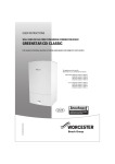
1
FLUE KIT INSTALLATION MANUAL
7 716 191 082 ROOM SEALED TELESCOPIC FLUE
7 716 191 171 ROOM SEALED LONGER TELESCOPIC FLUE
7 716 191 086 PLUME MANAGEMENT SYSTEM
GREENSTAR
60/100 HORIZONTAL FLUE
6 720 644 842b (2010/12)
6720644842-00.1Wo
FOR WORCESTER GREENSTAR CDi WALL HUNG, Si, i JUNIOR, i SYSTEM & Ri SERIES
OF GAS APPLIANCES INCLUDING BRITISH GAS VARIANTS
CONTENTS
CONTENTS
1
KEY TO SYMBOLS AND SAFETY PRECAUTIONS 3
1.1
Explanation of symbols . . . . . . . . . . . . . . . 3
1.2
Safety precautions . . . . . . . . . . . . . . . . . . 4
2
PRODUCT INFORMATION . . . . . . . . . . . . . . . . . 5
2.1
Telescopic flue components . . . . . . . . . . . 5
2.2
Flue extension components . . . . . . . . . . . 5
3
PRE-INSTALLATION . . . . . . . . . . . . . . . . . . . . . .
3.1
Flue terminal positions . . . . . . . . . . . . . . .
3.2
Flue measuring and cutting . . . . . . . . . . . .
3.2.1 Flue extension example . . . . . . . . . . . . . . .
3.2.2 Flue length guide . . . . . . . . . . . . . . . . . . . .
4
INSTALLATION . . . . . . . . . . . . . . . . . . . . . . . . .
4.1
Telescopic flue installation . . . . . . . . . . .
4.1.1 Installing the telescopic flue: . . . . . . . . .
4.1.2 Installing a high level telescopic flue: . . .
4.1.3 Flue terminal plume re-direction . . . . . . .
4.1.4 Extended flue installation . . . . . . . . . . . .
5
PRODUCT INFORMATION . . . . . . . . . . . . . . . . 14
5.1
Plume management system components 14
6
PRE-INSTALLATION . . . . . . . . . . . . . . . . . . . . . 15
6.1
Plume management terminal positions . . 15
6.2
Plume management options
& measurement . . . . . . . . . . . . . . . . . . . . 16
6.2.1 Determine the plume management
system length . . . . . . . . . . . . . . . . . . . . . . 17
6.2.2 Measuring for a plume management
system . . . . . . . . . . . . . . . . . . . . . . . . . . . 18
7
INSTALLATION . . . . . . . . . . . . . . . . . . . . . . . . . 19
7.1
Standard plume management installation 19
7.2
Extended plume management installation 20
7.3
Redirecting the flue discharge . . . . . . . . 21
7.4
Extended plume management installation
for a balcony / overhang . . . . . . . . . . . . . 22
8
SERVICE AND SPARES . . . . . . . . . . . . . . . . . . . 23
8.1
Servicing and maintenance . . . . . . . . . . . 23
8.2
Spare parts . . . . . . . . . . . . . . . . . . . . . . . 23
2
6
6
7
7
8
10
10
10
10
11
12
6 720 644 842b (2010/12)
KEY TO SYMBOLS AND SAFETY PRECAUTIONS
1
KEY TO SYMBOLS AND SAFETY PRECAUTIONS
1.1
EXPLANATION OF SYMBOLS
WARNING SYMBOLS
SYMBOLS
Cutting required
Safety instructions in this document are
framed and identified by a warning triangle
which is printed on a grey background.
Electrical hazards are identified by a
lightning symbol surrounded by a warning
triangle.
Signal words indicate the seriousness of the hazard in
terms of the consequences of not following the safety
instructions.
• NOTICE indicates possible damage to property or
equipment, but where there is no risk of injury.
Cutting not required
Table 3
Symbols
• CAUTION indicates possible injury.
• WARNING indicates possible severe injury.
• DANGER indicates possible risk to life.
IMPORTANT INFORMATION
Notes contain important information in
cases where there is no risk of personal
injury or material losses and are identified
by the symbol shown on the left. They are
bordered by horizontal lines above and
below the text.
ADDITIONAL SYMBOLS
Symbol
Meaning
B
a step in an action sequence
Æ
a reference to a related part in the
document or to other related documents
•
a list entry
–
Table 1
a list entry (second level)
Documentation symbols
ABBREVIATIONS
Ø
Diameter
RS
Room Sealed
Table 2
Abbreviations
6 720 644 842b (2010/12)
3
KEY TO SYMBOLS AND SAFETY PRECAUTIONS
1.2
SAFETY PRECAUTIONS
B DO NOT TURN ELECTRICAL SWITCHES ON OR OFF
Flue systems must not be modified in any way other than
as described in the fitting instructions. Any misuse or
unauthorised modifications to the appliance, flue or
associated components and systems could invalidate
the warranty. The manufacturer accepts no liability
arising from any such actions, excluding statutory rights.
B DO NOT STRIKE MATCHES OR SMOKE
SERVICING
B KEEP PEOPLE AWAY FROM THE AFFECTED AREA
Advise the user to have the system serviced annually by
a competent, qualified Gas Safe registered engineer.
Approved spares must be used to help maintain the
economy, safety and reliability of the appliance.
IF YOU SMELL GAS:
B CALL NATIONAL GAS EMERGENCY SERVICE ON
0800 111 999
B PUT OUT NAKED FLAMES
B OPEN DOORS AND WINDOWS
B TURN OFF THE CONTROL VALVE AT THE METER
IMPORTANT:
The service engineer must complete the Service Record
on the Benchmark Checklist after each service.
INSTALLATION REGULATIONS
Current Gas Safety (Installation & Use) Regulations:
Benchmark places responsibilities on both
manufacturers and installers. The purpose is to ensure
that customers are provided with the correct equipment
for their needs, that it is installed, commissioned and
serviced in accordance with the manufacturer's
instructions by competent persons and that it meets the
requirements of the appropriate Building Regulations.
The Benchmark Checklist can be used to demonstrate
compliance with Building Regulations and should be
provided to the customer for future reference.
Installers are required to carry out installation,
commissioning and servicing work in accordance with
the Benchmark Code of Practice which is available from
the Heating and Hotwater Industry Council who manage
and promote the scheme.
Visit centralheating.co.uk for more information.
HEALTH AND SAFETY
The appliance contains no asbestos and no substances
have been used in the construction process that
contravene the COSHH Regulations (Control of
Substances Hazardous to Health Regulations 1988).
COMBUSTION AND CORROSIVE MATERIALS
Do not store or use any combustible materials (paper,
thinners, paints etc.) inside or within the vicinity of the
appliance.
Chemically aggressive substances can corrode the
appliance and invalidate any warranty.
FITTING AND MODIFICATIONS
Fitting the appliance and any controls to the appliance
may only be carried out by a competent engineer in
accordance with the current Gas Safety (Installation and
Use) Regulations.
4
All gas appliances must be installed by a competent
person in accordance with the above regulations.
Failure to install appliances correctly could lead to
prosecution.
The appliance must be installed in accordance with, and
comply to, the current: Gas Safety Regulations, IEE
Regulations, Building Regulations, Building Standards
(Scotland) (Consolidation), Building Regulations
(Northern Ireland), local water by-laws, Health & Safety
Document 635 (The Electricity at Work Regulations
1989) and any other local requirements.
British Standards:
The relevant British Standards should be followed,
including:
BS5440:1
Flues and ventilation for gas appliances
of rated heating not exceeding 70kW
(net): Flues
BS5440:2
Flues and ventilation for gas appliances
of rated heating not exceeding 70kW
(net): Air Supply
BS6798:
Installation of gas fired boilers of rated
input up to 70kW (net)
Where no specific instruction is given, reference should
be made to the relevant British Standard codes of
Practice.
Timber framed building:
Where the boiler is to be fitted to a timber framed
building the guidelines laid down in BS5440: Part 1 and
IGE "Gas Installations in Timber Frame Buildings” should
be followed.
6 720 644 842b (2010/12)
PRODUCT INFORMATION
2
PRODUCT INFORMATION
2.1
TELESCOPIC FLUE COMPONENTS
2.2
FLUE EXTENSION COMPONENTS
60/100 mm TELESCOPIC FLUE KIT:
60/100mm - 220mm
Part No.: 7 716 191 082
1
60/100 mm LONGER TELESCOPIC FLUE KIT:
Part No.: 7 716 191 171
60/100mm - 1000mm
1
TELESCOPIC FLUE ASSEMBLY
2
WALL INNER SEAL
3
WALL OUTER SEAL
4
INSTALLATION MANUAL
5
ALUMINIUM TAPE
6
ACCESSORY PACK
Table 4
2
3
2
3
7
Part No.: 7 716 191 084
90° bend assembly plus: grease pack two No. 8 screws & grease sachet
60/100mm Support
bracket kit:
4
Part No.: 7 716 191 085
45° bend x 2 plus: grease pack two No. 8 screws & grease sachet
60/100mm 90° bend:
6
Part No.: 7 716 191 164
Flue connector, vertical plus: Screw pack
60/100mm 45° bend:
5
Part No.: 7 716 191 172
Extension tube assembly plus: grease pack two No. 8 screws & grease sachet
60/100 High level
horizontal flue adapter
4
Part No.: 7 716 191 083
Extension tube assembly plus: grease pack two No. 8 screws & grease sachet
60/100mm - 2000mm
Telescopic flue components
1
Part No.: 7 716 191 133
Extension tube assembly plus: grease pack two No. 8 screws & grease sachet
Part No.: 7 716 191 092
Wall bracket, swivel bracket, clamp, fixing
screws and wall plugs (6 in kit)
Table 5
Flue extension components
2
6
1
6720644842-01.2Wo
5
Telescopic flue components
5
4
7
6
6720644842-02.2Wo
Fig. 1
3
Fig. 2
6 720 644 842b (2010/12)
Flue extension components
5
PRE-INSTALLATION
3
PRE-INSTALLATION
3.1
FLUE TERMINAL POSITIONS
All measurements in millimetres
300
6
Dormer
Window
500
25
5
7
14
1,500
Velux Window
400
25
8
10
9
11
200
Drainpipe
25
4
3
500
600
500
300
1,200
300
12
13
1,500
300
2
Boundary
Window
300
15
600
1 300
Fig. 3
6720643895-13.1Wo
Flue terminal positions
NOTE:
B All measurements are the minimum clearances required.
B Terminals must be positioned so to avoid combustion products entering the building.
B Support the flue at approximately one metre intervals and at a change of direction, use suitable
brackets and fittings (Flue bracket part numbers.: 100mm - 7 716 191 092.
Key to illustration
1. Flue clearance must be at least 300mm from the
ground. Terminal guards must be fitted if the flue is
less than 2 metres from the ground or if a person
could come into contact with the flue terminal.
2. 600mm distance to a boundary, unless it will cause
a nuisance. BS 5440: Part 1 recommends that care is
taken when siting terminals in relation to
boundaries.
3. 600mm minimum clearance from a skylight to a
vertical flue.
4. Vertical flue clearance, 500mm to non-combustible
building material, and 1,500mm clearance to
combustible building material.
5. The dimension below eaves, gutters, pipes and
drains can be reduced to 25mm, as long as the flue
terminal is extended to clear any overhang. Any
external flue joints must be sealed with a suitable
silicon sealant.
6. 500mm clearance to any vertical structure on a roof,
600mm to room sealed flue or 1,500mm to an open
flue.
7. 1,500mm between a vertical flue terminal and a
window or dormer window.
6
8. 400mm from a pitched roof or in regions with heavy
snow fall 500mm.
9. The flue cannot be lower than 1,000mm from the top
of a light well due to the build up of combustion
products.
10. 2,000mm below a Velux window, 600mm above or
to either side of the Velux window.
11. 200mm below eaves and 75 mm below gutters,
pipes and drains.
12. 1,200mm between terminals facing each other.
13. 300mm to an internal or external corner.
Installations in car ports are not
recommended.
14. The dimension below eaves, balconies and car ports
can be reduced to 25 mm, as long as the flue
terminal is extended to clear any overhang.
Any external flue joints must be sealed with suitable
silicon sealant.
15. 300mm above, below and either side of an opening
door, air vent or opening window.
6 720 644 842b (2010/12)
PRE-INSTALLATION
3.2
FLUE SYSTEMS IN VOIDS
When installing a new flue system consider the following
information.
2
2
4
CAUTION: Flue systems in ceilings or roof
voids.
X
X
Where a flue system is not going to be
accessible, provision for access must be
made for service and inspection:
B Voids containing concealed flues must
have at least one inspection hatch no less
than 300mm square.
6
5
5
X
B Inspection hatches should be located at
changes of flue direction.
X
7
1
1
Boiler
B If this is not possible, bends should be
viewable from both directions.
X
FLUE SYSTEMS IN CEILINGS OR ROOF VOIDS
When installing a flue system in a ceiling or roof void, the
following points must be observed:
2. The flue system must not pass through a neighbouring
property, as access may not be possible at the time of
inspection.
6
X
B Flue joints within the void must not be
more than 1.5m from the edge of the
inspection hatch.
1. Access points for inspection of the flue system must
be sufficiently sized for visual inspection, particularly
at any joint in the flue system.
1
1
Boiler
3
6720645523-44.1Wo
Fig. 4
Flues in voids
X
This dimension must not be more than 1.5
metres
3. Any access must not contravene any other building
regulations or fire regulations. Refer to Building
Regulations Approved Documents B, L and E.
1
Inspection hatch
2
Flue terminal
4. The access panels must be no less than 300mm
square. Larger access panels can be considered if the
whole flue system needs to be viewed.
3
Concealed flue connection
4
External wall
5. The flue system must be adequately supported at
regular interval, approximately every 1.5 metres.
5
Internal wall
6
Any intervening joints must be visible within
1.5 metres of the inspection hatch
7
Accessible flue connection
Table 6
ANNUAL INSPECTION
When the flue system is inspected under the annual
service, the engineer must inspect and confirm that:
B the flue system is continuous without any breaks.
B all joints in the flue system are sound and correctly
assembled according to the manufacturers
instructions.
B the flue has a fall of 3° (52 millimetres per metre)
back to the boiler.
6 720 644 842b (2010/12)
7
PRE-INSTALLATION
3.3
FLUE MEASURING AND CUTTING
NOTE: FLUE LENGTH
B Do not exceed the maximum straight length for a horizontal 60/100mm flue or a 60mm plume
management system (if used) as stated in the relevant Installation, Commissioning & Servicing
Instructions manual or addendum.
Cutting the flue to an exact measurement is not normally required as the telescopic flue terminal can allow
for some adjustment.
3.3.1
FLUE EXTENSION EXAMPLE
Maximum effective flue lengths
The terminal end projects beyond the
outside wall by the distance shown in fig. 5
L max. (mm)
Greenstar Si, i Junior, i System & Ri
Series
4600
1. Measure the flue length L from the centre line of the
flue turret, along the route of the flue system, to the
face of the outside wall.
Greenstar 30CDi System & Regular
7900
Greenstar 27CDi
10000
2. Select the required number of extensions and bends
to achieve the require flue run.
Greenstar 30CDi
7000
Greenstar 37CDi
6500
3. If the flue requires cutting:
Greenstar 42CDi
6000
British Gas 430i
7900
British Gas 532i
7000
British Gas 537i
6500
British Gas 542i
6000
Greenstar 40CDi Regular
– Set the telescopic flue length to 400mm.
– Secure the joint with the screw and tape provided.
– Subtract 400mm from the measured flue length L
to determine the amount to be cut of an extension.
Table 7
6000
Maximum flue lengths
L
50
110
R
E
T
50
6720644842-03.1Wo
Fig. 5
Flue length determination
L
Effective length of the flue system
R
Actual length of the flue sections (L-50 = R)
E
Extension flue length
T
Telescopic flue length
Table 8
8
Key to figure 5
6 720 644 842b (2010/12)
PRE-INSTALLATION
3.3.2
FLUE LENGTH GUIDE
Flue length range (mm) Cut
45° BENDS
Number of extensions
130 - 265
YES
None
350 - 570
NO
None
570 - 790
NO
None
790 - 1300
YES
1
1300 - 1520
NO
1
1520 - 2250
YES
2
2250 - 2470
NO
2
2470 - 3200
YES
3
3200 - 3420
NO
3
3420 - 4150
YES
4
4150 - 4370
NO
4
4370 - 4600
YES
5
Table 9
This application can only be used with the
Si, i Junior and i System boilers.
Figure 7 shows a possible application for a 45° bend
that could be used if fluing from the right or left from the
boiler. In this application the flue would be 100mm
closer to the wall.
WALL
189 mm
100 mm
Flue extension guidance up to 4600mm
FLUE BENDS
1
NOTE: EFFECTIVE LENGTH
6720644842-06.1Wo
B Each flue bend is rated as a certain
straight length of flue, refer to table 10
below. The “effective length” of each
bend is added to the straight length of
flue. Adding bends to the flue system
reduces the actual flue length available.
The effective length of the flue must not
exceed that stated in the relevant
appliance Installation, commissioning
and service manual.
Fig. 7
45° Bend offset dimensions
ADJUSTING THE TELESCOPIC FLUE LENGTH,
STANDARD OR LONGER VERSION
L
570 mm
350 mm
Effective length in metres
Si, i junior,
i System & Ri
Bend
CDi
90°
2
1.5
45°
1
0.75
Table 10
90° BENDS
Figure 6 shows the actual length added by a 90° bend
when used in either orientation.
2
Fig. 8
1
6720643895-30.1Wo
Standard telescopic flue
Extend tube (1) by withdrawing from tube (2) to achieve
the flue length required, between 350- 570mm.
If using the “longer” telescopic flue, extend tube (1) by
withdrawing from tube (2) to achieve the flue length
required, between 570- 790mm.
L
111 mm
790 mm
570 mm
74 mm
960 mm
2
Fig. 9
6720644842-04.1Wo
Fig. 6
90° Bend offset dimensions
6 720 644 842b (2010/12)
1
6720644842-34.1Wo
Longer telescopic flue
Secure with screw provided and seal joint with the
aluminium tape supplied.
9
PRE-INSTALLATION
REDUCING THE TELESCOPIC FLUE LENGTH
Ensure that the TOP label of both sections
are aligned before securing the two parts at
the required length.
From standard telescopic flue
265 mm
1
The flue terminal MUST be fitted with the 'TOP' label
uppermost to allow the correct fit and use of the plume
management system.
B Remove securing screws (3) to detach the terminal
assembly from the turret.
B Slide terminal section (2) from the terminal assembly
and discard.
130 mm
MIN
4
6
5
From longer telescopic flue
485 mm
1
B To use terminal (1) without cutting remove the
location lug (4) on the inner flue tube (5) and remove
any burrs.
3
130 mm
MIN
4
6
6720644842-35.1Wo
5
Fig. 11
Further reduction
REDUCING EXTENSION FLUE TUBE LENGTH
A 220mm short extension is available
2
Fig. 10
1
6720643895-31.1Wo
Reducing the telescopic terminal
To reduce the telescopic flue length further:
B Mark the length required for the terminal as shown in
figure 11 (min. 130mm) and cut square, taking care
not to damage the tubes.
B Remove any burrs and chamfer the outer edge of the
tubes to assist ease of connection and prevent seal
damage.
B Mark the extension tube to the required distance,
measuring from the socket end and cut the tube
square, taking care not to damage the tubes.
B Remove any burrs and chamfer the outer edge of the
tubes to ease the connection and prevent damage to
the seals.
The aluminium tape is not required when
reducing the terminal.
2
1
6720644842-07.1Wo
Fig. 12
10
Cutting an extension tube
6 720 644 842b (2010/12)
INSTALLATION
4
INSTALLATION
4.1
TELESCOPIC FLUE INSTALLATION
4.1.1
INSTALLING THE TELESCOPIC FLUE:
B When using a 100 mm diameter flue, a 125mm
diameter hole through the wall is required.
However, if installing the flue from inside the property
and fitting the weather sealing collar before the flue is
pushed through the hole, then a 150 mm diameter
hole is required.
1.
1. 1.
4.
B The flue turret of the 100 mm flue has an in-built 3°
angle.
B If extensions are to be added then the complete flue
must rise at an angle of 3° or 52mm for every metre of
flue length.
3.
2.
110
B Drill the hole using a suitable core drill.
1. Referring to figure 13, set the flue length to the
distance required, secure with screws.
2. Seal the joint with the aluminium tape.
3. Slide the inner wall seal onto the terminal.
4. If fitting from inside the building; slide the outer wall
seal onto the terminal, locating the ridge on the seal
with the groove on the terminal.
Fig. 14
4.1.2
Telescopic flue installation
INSTALLING A HIGH LEVEL TELESCOPIC FLUE:
1. Referring to figure 15, remove and retain the screws
securing the telescopic flue to the turret. Disconnect
the flue from the turret and discard the turret.
2. Slide the inner wall seal on to the terminal.
3. Set the telescopic flue to the required length and
secure with the screws provided.
3.
2.
6720643895-33.1Wo
TOP
4. Seal the joint with the aluminium tape supplied.
5. If fitting the flue from inside the property, slide on the
outer wall seal, locating the ridge on the seal with the
groove on the terminal.
1.
1.
4.
1.
6720644842-08.1Wo
Fig. 13
Telescopic flue
4.
1. Referring to figure 14, remove the three screws
securing the flue outlet to the boiler.
3.
2. Check the boiler flue seal is correctly seated and
apply silicone grease.
2.
3. Position terminal through the flue opening in the wall
to the outside of the building by the distance shown.
4. Align the flue turret to the boiler flue outlet with flat
facing to the rear of the boiler. Push the flue turret
straight down into the boiler flue outlet.
5.
6720644842-31.1Wo
Fig. 15
Preparing the telescopic flue
B Fit the screws remove in step 1 to secure flue turret.
B If fitting the outer seal from outside the building, slide
the outer wall seal onto the terminal as shown,
locating the ridge on the seal with the groove on the
terminal.
6 720 644 842b (2010/12)
11
INSTALLATION
1. Referring to figure 16, fit the telescopic flue firmly
into the 90° bend.
2. Fit the 90° bend firmly into the extension piece.
3. Fit the vertical flue adapter to the end of the
extension.
4.1.3
FLUE TERMINAL PLUME RE-DIRECTION
The flue discharge can be re-directed to allow some
plume redirection control. Alternatively, a complete
plume management system can be fitted to the flue
terminal.
RE-DIRECTING THE FLUE DISCHARGE
NOTE: DO NOT ROTATE THE COMPLETE
FLUE TERMINAL ASSEMBLY.
1.
B The flue terminal outlet has built-in stops
to limit rotation for horizontal fluing.
This allows condensate to run back to the
boiler for safe disposal.
Do not attempt to force beyond the limit
stops.
2.
1. Using a suitable tool, unclip the end of the terminal.
2. Rotate the end by 180° and refit the terminal end,
ensuring to engage the clips to secure.
3.
6720644842-33.1Wo
Fig. 16
Assembling the extensions
3. Loosen the screws securing the entire outlet
assembly and rotate by ± 80° to the desired position
and re-secure the assembly.
1. Referring to figure 17, remove and discard the three
screws securing the flue outlet in the boiler.
2. Check the boiler flue seal is correctly seated and
apply silicone grease.
1.
3. Position terminal through the flue opening in the wall
to the outside of the building by the distance shown.
4. Align the vertical flue adapter to the boiler flue outlet
with flat facing to the rear of the boiler.
Push the adapter straight down into the boiler flue
outlet.
1
2
5. Secure the telescopic flue bends and extensions with
the screws provided.
2.
6. Secure the vertical flue adapter to the boiler with the
screws provide in the adapter kit.
180°
±80°
1.
3.
3 1
5.
6.
3.
6720643895-34.1Wo
110
Fig. 18
Plume redirection
4.
2.
Fig. 17
12
6720644842-32.1Wo
Fitting the high level horizontal flue
6 720 644 842b (2010/12)
INSTALLATION
4.1.4
NOTE: OUTLET POSITIONS
EXTENDED FLUE INSTALLATION
NOTE: CONDENSATE DISPOSAL
B The flue terminal outlet position must
follow those stated in figure 3.
When redirecting the flue discharge the
terminal end must be at least 1500mm
from any opening in the direction of the
discharge to prevent combustion
products from entering the building as
shown
B All horizontal flue sections must rise by at
least 52mm per metre away from the
boiler to ensure that the condensate
flows back into the boiler for safe
disposal via the condensate waste pipe.
2m
1m
1
52mm
Fig. 20
104mm
6720644842-10.1Wo
Slope for condensate disposal
To ease assembly of the flue components,
lightly grease the seals with the solvent-free
grease supplied.
Check all the seals are properly seated in
the grooves provided and are in good
condition.
All flue joints must be sealed to prevent
leakage of condensate and flue products.
4
2
3
6720643895-119.1Wo
Fig. 19
Plume distance to opening
1
Opening in building
2
Flue discharge
3
Terminal end
4
Minimum 1500mm from an opening in the
building
Table 11 Key to figure 19
6 720 644 842b (2010/12)
13
INSTALLATION
INSTALLING AN EXTENDED FLUE
The flue terminal MUST be fitted with the
“TOP” upper most to allow the correct fit
and use of the plume management system.
1. Remove the screws retaining the flue to the turret.
2. Disconnect the flue (1) from the turret (2).
B Refer to figure 23 and slide the support clamps (1)
onto the additional flue extensions (2).
1. Working from the boiler, fit the support clamps (1)
and extensions (2), to take the weight of the flue.
2. Drill two holes, 180° apart, through the outer flue
tube of each extension, take care not to drill into the
inner flue tube, and secure with the screws provided.
3. Slide the support clamp (optional item 3) onto the
flue extension as shown.
2.
1.
4. Push fit the extension (4) as far as possible into the
flue turret.
5. Drill through the turret screw holes into the flue outer
tube, take care not to drill into the inner tube.
Secure the extension to the turret with the screws
removed earlier.
Fig. 23
4
1.
1.
3
2
1
1
6720644842-12.1Wo
Extensions
1. Refer to figure 24 and slide the inner wall seal onto
the terminal.
– If fitting the flue from inside the building, slide the
outer wall seal onto the terminal, locating the ridge
on the seal with the groove on the terminal.
4.
3.
2. Position the terminal assembly through the opening in
the wall to the outside.
2.
5.
3. Push the flue into the extension as far as possible.
1
6720644842-09.1Wo
Fig. 21
2.
2
5.
2
1.
Flue extensions
1. Remove the three screws from around the flue outlet
on the boiler and retain.
For CDi models, the screw pack is in the boiler.
2. Ensure that the boiler flue seal is seated correctly,
and apply silicone grease to the seal.
3. Fit the flue turret to the boiler flue outlet and rotate
to the direction required, ensuring the flat on the
clamp ring is facing the rear of the boiler.
1.
4. Drill two holes, 180° apart, through the outer flue
tube of each extension, take care not to drill into the
inner flue tube, and secure with the screws provided.
5. If using the telescopic flue, slide the assembly until
the flue terminal projects out of the wall by 110mm.
– Secure the flue with the screw provide and seal the
joint with the tape provided.
B If fitting from outside the building, slide the outer wall
seal onto the terminal, locating the ridge on the seal
with the groove on the terminal.
4.
1.
TOP
1. 1.
3.
3.
4.
5.
2.
110
2.
6720644842-11.1Wo
Fig. 22
14
Extended flue turret fitting
6720644842-13.1Wo
Fig. 24
Extended flue
6 720 644 842b (2010/12)
PRODUCT INFORMATION
5
PRODUCT INFORMATION
5.1
PLUME MANAGEMENT SYSTEM COMPONENTS
PLUME MANAGEMENT COMPONENTS
Ø 60mm PLUME MANAGEMENT KIT comprising:
EXTENSION COMPONENTS
Ø 60mm EXTENSION comprising:
Part No.: 7 716 191 086
Part No.: 7 716 191 087
1
Terminal bend
5
Extension 1000mm
2
Extension 500mm
6
Clamp pack
3
Outlet assembly
90° BEND comprising:
4
Clamp pack
Part No.: 7 716 191 088
Table 12 60mm Plume management kit
7
90° Bend
45° BEND comprising:
Part No.: 7 716 191 089
8
1
45° Bend x 2
Terminal guard
Part No.: 7 716 191 176
2
9
Terminal guard
Table 13 60mm Extension
3
5
4
6
6720644842-14.1Wo
Fig. 25
Plume management kit components
7
8
9
6720644842-15.2Wo
Fig. 26
6 720 644 842b (2010/12)
Plume management extension components
15
PRE-INSTALLATION
6
PRE-INSTALLATION
6.1
PLUME MANAGEMENT TERMINAL POSITIONS
All measurements in millimetres
±45°
Plume management deflector:
Flue Exhaust
Outlet
8
180°
Air Intake
7
±80°
3
200
300
2
1,200
Balcony
4
150
600
100
200
200
200
1
25
300
150
Window
300
Window
300
200 5
Window
Door
Boundary
25
150
150
150
6720643895-14.1Wo
Drainpipe
Fig. 27
6
Plume terminal positions
NOTE:
B Refer to figure 3 for all concentric flue terminal positions unless the flue position is specified on the
figure above “Plume terminal positions”.
B All measurements are the minimum clearances required.
B Terminals must be positioned so to avoid combustion products entering the building.
B Support the flue at approximately one metre intervals and at a change of direction, use suitable
brackets and fittings.
Key to illustration
1. 600 mm distance to a boundary or surface facing a
boundary, unless it will cause a nuisance. BS 5440:
Part 1 recommends that care is taken when siting
terminals in relation to boundaries.
2. Internal/external corners. The air intake clearance
can be reduced to 150 mm providing the flue
exhaust outlet has a 300 mm clearance.
3. The flue cannot be lower than 1,000 mm from the
top of the light well due to the build up of
combustion products.
4. 1,200 mm between air intake and facing terminal.
5. Clearance no less than 200 mm from the lowest
point of the balcony or overhang.
Installations in car ports are not
recommended.
6. 1,200 mm from an opening in a car port on the same
wall i.e. door or window leading into dwelling.
16
7. Using a Plume Management Kit the air intake
measurement can be reduced to 150 mm providing
the flue exhaust outlet has a 300 mm clearance.
Plume kits running horizontally must have a 10° fall
back to the boiler for proper disposal of condensate.
For details on specific lengths see relevant boiler
Technical & Specification information.
8. This feature allows some basic plume re-direction
options on a standard telescopic horizontal flue
terminal.
300 mm minimum clearances to a opening e.g.
window.
However the minimum clearance to an opening in
direction that the plume management is facing, must
be increased to 1,500 mm.
Where the flue is less than 150 mm to a drain pipe
and plume re-direction is used the deflector should
not be directed towards the drainpipe.
6 720 644 842b (2010/12)
PRE-INSTALLATION
6.2
PLUME MANAGEMENT OPTIONS &
MEASUREMENT
1
3
NOTE: PLUME MANAGEMENT
B All plume management sections must rise
away from the terminal by a minimum of
173mm per metre (10°) to allow the
condensate to drain back to the boiler.
2
4
The figure 28 shows the components required for typical
plume management configurations.
5
PLUME MANAGEMENT KIT
7
6720644842-18.1Wo
1
3
4
Fig. 30
Plume management with bend
2
1
3
6720644842-16.1Wo
Fig. 28
Plume management components
1
Terminal bend
2
Extension 500mm
3
Outlet assembly
4
Clamp
2
4
5
5
Table 14 Key to figure 28
PLUME MANAGEMENT OPTIONAL KIT
1
3
2
4
5
6720644842-19.1Wo
6720644842-17.1Wo
Fig. 29
Fig. 31
Plume management with straight extension
Optional components
NOTE: PLUME MANAGEMENT LENGTH
5
Extension tube 100mm and Clamp
6
90° Bend
7
45° Bend
Table 15 Key to figure 29
6 720 644 842b (2010/12)
B Measurement M must be a minimum of
500mm and must not exceed the
maximum straight length for a horizontal
Ø 60/100mm flue or a 60mm plume
management system as stated in the
relevant appliance Installation,
commissioning and service manual or
addendum.
17
PRE-INSTALLATION
Fig. 32
DETERMINE THE PLUME MANAGEMENT SYSTEM LENGTH
Effective lengths L and M
8,000
Effective Flue length ‘L’ mm
Maximum Plume Length
for all boilers
MINIMUM PLUME KIT LENGTH 500 mm
6.2.1
7,000
6,000
5,000
4,000
3,000
2,000
1,000
27CDi
Si, i Junior, i System & Ri
30CDi Regular, System &
BG430/i
30CDi
BG532/i
37CDi & BG537/i
42CDi, 40CDi Regular &
BG542/i
0
0
Fig. 33
500
1,500
2,500
3,500
Plume management length allowed ‘M’ mm
4,500
Effective flue lengths versus plume management lengths
PLUME LENGTH
The minimum plume length for all boilers
stated on the front page of this manual is
500mm.
Refer to figure 33 to determine the appropriate plume
length versus the flue length (L).
For the CDi range of boilers, the available plume length
(M) is reduced as the flue length (L) increases. Any flue
must have a minimum of 500mm plume length.
The Si, i System, i Junior and Ri can use up
to 4,500mm of plume management
regardless of flue length.
The flue length is the effective length (L), which includes
the effective length of any bends plus the straight flue
lengths.
Once the length L is know, find that value on the vertical
scale of the graph and read that across to the line that
represents the installed boiler.
From that point read down to the horizontal scale to
determine the maximum plume length (M) allowed.
18
6 720 644 842b (2010/12)
PRE-INSTALLATION
6.2.2
MEASURING FOR A PLUME MANAGEMENT SYSTEM
All boilers have a maximum permissible
plume management length, refer to
figure 33.
1. Measure the plume management flue (M) from the
centre of terminal, along the required route to the
centre of the plume outlet.
1
6720644842-20.1Wo
Fig. 34
Plume management length M
ADDITIONAL BENDS:
2. Adding bends to the plume management system
reduces the actual plume management length. Each
bend has an equivalent straight length and must be
factored into the overall effective length.
– 90° bend is equivalent to 1500mm.
– 45° bend is equivalent to 750mm
2
6720644842-21.1Wo
Fig. 35
Plume management bends
EXAMPLE:
Using two 45° bends will reduce the permissible length
by 1500mm.
A Greenstar 28i junior has a maximum permissible plume
management length of 4500mm, so using two 45° bends
will reduce the straight length to 3000mm.
6 720 644 842b (2010/12)
19
INSTALLATION
7
INSTALLATION
7.1
STANDARD PLUME MANAGEMENT INSTALLATION
To ease assembly of the flue components,
lightly grease the seals with the solvent-free
grease supplied.
Check all the seals are properly seated in
the grooves provided and are in good
condition.
All flue joints must be sealed to prevent
leakage of condensate and flue products.
4.
65 mm
3.
NOTE: PLUME MANAGEMENT
B All plume management sections must rise
away from the terminal by a minimum of
173mm per metre (10°) to allow the
condensate to drain back to the boiler.
4.
±80°
FITTING THE STANDARD PLUME MANAGEMENT
SYSTEM:
2.
Refer to figure 36 for terminal bend installation.
1.
1. Remove and retain the screws and discard the
terminal end.
2. Fit the new terminal bend to the terminal outlet and
secure with the screws removed previously.
3. Mark the position for the wall clamp so that it
coincides with the extension tube just below the top
fitting (Refer to figure 37 point 2).
Drill a hole to suit the wall plug and fit the wall plug.
6720644842-22.1Wo
Fig. 36
Terminal bend installation
±45°
4. Screw the clamp into the wall plug to the distance
shown in figure 36.
3.
NOTE: DO NOT ROTATE THE COMPLETE
FLUE TERMINAL ASSEMBLY.
2.
4.
5.
B The flue terminal outlet has built-in stops
to limit rotation for horizontal fluing to
allow condensate to run back to the
boiler for safe disposal.
Do not attempt to force beyond the limit
stops.
2.
Refer to figure 37 plume management installation.
1. Push the extension tube fully into the terminal bend,
then withdraw the tube by approximately 10mm to
allow for expansion.
1.
2. Secure the extension to the wall with the clamp and
screws provided.
10 mm
1.
3. Push the outlet assembly fully into the extension tube.
4. Rotate the outlet assembly to the required direction.
5. Secure the outlet to the extension with the selftapping screw provided.
20
6720644842-23.1Wo
Fig. 37
Plume management installation
6 720 644 842b (2010/12)
INSTALLATION
7.2
EXTENDED PLUME MANAGEMENT
INSTALLATION
To ease assembly of the flue components,
lightly grease the seals with the solvent-free
grease supplied.
Check all the seals are properly seated in
the grooves provided and are in good
condition.
All flue joints must be sealed to prevent
leakage of condensate and flue products.
Refer to figure 38 and assemble the plume extensions.
1. Mark the position for the wall clamp that coincides
with the extension tube, as shown.
Drill a suitable hole and fit the wall plug.
Screw the clamp into the wall plug as shown.
2. Push the extension tube fully into the terminal bend,
then withdraw the tube by approximately 10mm to
allow for expansion.
3. Secure the extension to the wall with the clamp and
screws provided.
NOTE: PLUME MANAGEMENT
4. Mount the other extension tubes as before and secure
to the wall
B All plume management sections must rise
away from the terminal by a minimum of
173mm per metre (10°) to allow the
condensate to drain back to the boiler.
6. Rotate the outlet assembly to the required direction
and secure the outlet to the extension with the selftapping screw provided.
5. Push the outlet assembly fully into the extension tube.
FITTING THE EXTENDED PLUME MANAGEMENT:
±45°
1. Refer to figure 36 and remove and retain the screws
securing the terminal end and discard the terminal
end.
4.
2. Fit the terminal bend to the terminal outlet and secure
with the screws retained earlier.
5.
6.
3. If required, rotate the terminal bend for angled fluing.
3.
NOTE: DO NOT ROTATE THE COMPLETE
FLUE TERMINAL ASSEMBLY.
1.
3.
B The flue terminal outlet has built-in stops
to limit rotation for horizontal fluing to
allow condensate to run back to the
boiler for safe disposal.
Do not attempt to force beyond the limit
stops.
65 mm
2.
1.
2.
2.
1.
10 mm
3.
2.
±80°
6720644842-25.1Wo
Fig. 38
6 720 644 842b (2010/12)
Plume extensions
21
INSTALLATION
7.3
INSTALLING A TERMINAL GUARD
A Terminal guard must be fitted if the flue is less than
two metres from the ground or if a person could come
into contact with the flue terminal outlet.
NOTE: The terminal end must not be
swivelled inside the guard. The terminal end
must be mounted at right angles with
respect to the wall.
The terminal guard does not have to be
fitted over the flue inlet, but is
recommended to protect the flue from third
party damage.
B Fit the terminal guard centrally over the flue inlet or
outlet.
B Mount the terminal guard to the wall utilising the
three mounting points attached to the guard.
B Fold the gates in the order stated below or the gates
will not latch properly.
1. Fold the single pronged gate in and latch onto the
guard frame.
2. Fold the two pronged gate in and latch onto the guard
frame.
1.
2.
6720646219-31.1Wo
Fig. 39
Terminal guard - flue outlet
2.
1.
6720646219-32.1Wo
Fig. 40
22
Terminal guard - flue inlet
6 720 644 842b (2010/12)
INSTALLATION
7.4
REDIRECTING THE FLUE DISCHARGE
The plume deflector can be adjusted to redirect the flue discharge.
NOTE: FLUE DISCHARGE
B The Plume terminal outlet position must follow those stated in figure 27. When redirecting the flue
discharge the outlet must be at least 1500mm from and angle at least 45° away from any opening in the
direction of the discharge, as shown. This is to prevent combustion products from entering the building.
4
V
45°
2
1
3
6720644842-28.1Wo
Fig. 41
Plume direction conditions
1
Opening in the building i.e. air brick, window.
2
Direction of flue products, must be more than
45° from the wall or structure
3
Plume terminal
4
At least 1500mm from any opening in the
building
Table 16 Key to figure 41
6 720 644 842b (2010/12)
23
INSTALLATION
7.5
EXTENDED PLUME MANAGEMENT INSTALLATION FOR A BALCONY / OVERHANG
To ease assembly of the flue components,
lightly grease the seals with the solvent-free
grease supplied.
Check all the seals are properly seated in
the grooves provided and are in good
condition.
All flue joints must be sealed to prevent
leakage of condensate and flue products.
4.
100 mm
1. Refer to figure 36 and remove and retain the screws
and terminal end.
1.
5.
2. Fit the terminal bend to the terminal outlet and secure
with the screws removed earlier.
3. If required, rotate the terminal bend for angled fluing.
3.
2.
NOTE: DO NOT ROTATE THE COMPLETE
FLUE TERMINAL ASSEMBLY.
B The flue terminal outlet has built-in stops
to limit rotation for horizontal fluing to
allow condensate to run back to the
boiler for safe disposal.
Do not attempt to force beyond the limit
stops.
3.
2.
1.
3.
1. Refer to figure 42 and mark the position for the wall
clamp that coincides with the extension tube just
below the top fitting.
Drill a suitable hole and fit the wall plug.
Screw the clamp into the wall plug as shown.
65 mm
2. Push the extension tube fully into the terminal bend,
then withdraw the tube by approximately 10mm to
allow for expansion.
2.
1.
3. Secure the extension to the wall with the clamp and
screws provided.
2.
B Mount the other extension tubes as before and secure
to the wall.
10 mm
Ensure that the plume outlet, projects at
least 100mmpassed the balcony/overhang.
4. Remove the screw from the terminal end and remove
the grill.
5. Drill a hole through the plume outlet end and secure
the grill in place.
24
6720644842-26.1Wo
Fig. 42
Under balcony installation
6 720 644 842b (2010/12)
SERVICE AND SPARES
8
SERVICE AND SPARES
8.1
SERVICING AND MAINTENANCE
An annual visual check of the plume management kit
must be carried out.
NOTE: PAINTING
B DO NOT paint the plume management kit!
8.2
SPARE PARTS
Ø 60/100mm Telescopic horizontal flue
1
Collar - flue turret:
Part Number: 8 716 111 254 0
2
Air sample point plug - flue turret:
Part Number: 8 716 111253 0
3
Flue sample point cap with seal - flue turret:
Part Number: 8 716 111 252 0
4
Terminal outlet assembly:
Part Number: 8 716 111 209 0
5
Wall seal - Inner:
Part Number: 8 716 111 211 0
6
Wall seal - Outer:
Part Number: 8 716 111 212 0
Table 17 Key to figure 43
1
2
5
3
6
4
6720644842-27.1Wo
Fig. 43
Spare parts
6 720 644 842b (2010/12)
25
NOTES
26
6 720 644 842b (2010/12)
NOTES
6 720 644 842b (2010/12)
27
WORCESTER, BOSCH GROUP:
TECHNICAL SUPPORT:
0844 892 3366
APPOINTMENTS:
0844 892 3000
SPARES:
01905 752571
LITERATURE:
0844 892 9800
TRAINING:
01905 752526
SALES:
01905 752640
WEBSITE:
Worcester, Bosch Group
Cotswold Way, Warndon, Worcester WR4 9SW.
Tel. 0844 892 9900
Worcester, Bosch Group is a brand name of Bosch Thermotechnology Ltd.
6 720 644 842b (2010/12)
worcester-bosch.co.uk