1
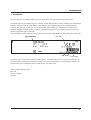
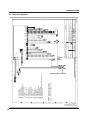
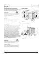
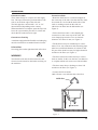
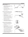
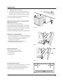
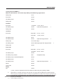
Service manual
Dishwasher
Type: DW20.1, DW20.2, DW20.3, DW20.4
Asko Cylinda AB/After Sales
Box 344
SE-532 24 Skara
Sweden
2
Contents
1. Introduction .............................................................................................................. 5
2. Technical data ........................................................................................................... 7
2.1 Technical information ....................................................................................... 7
2.2 Components and measured values ................................................................... 8
2.3 Connection diagram ....................................................................................... 10
2.4 Functional description of components ............................................................. 11
3. Installation.............................................................................................................. 14
4. Settings ................................................................................................................... 18
4.1 Programme .................................................................................................... 18
4.2 Time display ................................................................................................... 18
4.3 Options .......................................................................................................... 19
5. Service menu .......................................................................................................... 27
5.1 Activation of service menu ............................................................................. 27
5.2 Programme flow description .......................................................................... 29
6. Troubleshooting ...................................................................................................... 31
6.1 Most common faults ....................................................................................... 31
6.2 Fault indication .............................................................................................. 33
6.3 Fault codes ..................................................................................................... 34
7. Tools ....................................................................................................................... 35
7.1 Tools .............................................................................................................. 35
7.2 Special tools ................................................................................................... 35
Register ...................................................................................................................... 36
3
INTRODUCTION
1. Introduction
In your hand you are holding ASKO’s Service Manual for the new generation of dishwashers.
The dishwashers in the DW20 range are available in four different basic models with the type designations
DW20.1, DW20.2, DW20.3 and DW20.4. Presented on the following page are the different panels
available for each type, which lets you readily identify the machine type. The different variants have
different designations from market to market. The type designation is most important when you need to
identify a particular type of machine.
You can find this on the machine rating plate positioned on the right-hand side of the inner part of the door.
Type designation
Item number
Year Week
Serial number
It must be easy to carry out servicing on dishwashers. It is important for you, as a service technician, to
benefit from the conditions necessary to enable you to work in an effective and satisfactory fashion. We
hope that this Service Manual will be a useful tool in your daily work.
Asko Cylinda AB/After Sales
Box 344
SE-532 24 Skara
Sweden
5
INTRODUCTION
DW20.1
DW20.1 is available in two variants, either with none or with two options. Both have four set programmes
and operating controls on the front of the panel.
DW20.2
DW20.2 is a control unit with a large display on the front of the panel. It has six set programmes and none
or three or five options.
DW20.3
The buttons are on the top side of the control unit in the DW20.3. The unit has six set programmes and is
available in two models - with three or five options.
DW20.4
DW20.4 is a control unit with ten set programmes, a number of different options and with a single display
(LCD) on the top side of the panel.
The DW20.3 and DW20.4 control units are used both for fully integrated and standard models. The other
control units are used only on standard models.
6
TECHNICAL DA
ATT A
2. Technical data
2.1 Technical information
Height:
Width:
Depth:
Weight:
Capacity*:
Water pressure:
Connection:
Max connection power:
820 - 870 mm (860 - 870 mm)
596 mm
550 mm
42 kg/45 kg with water softener
12 place settings
0.03–1.0 MPa (0.3–10 kp/cm2)
1-phase, 230 V, 50 Hz 10 A**
1 900 W**
*According to standard EN 50242
**See rating plate
7
TECHNICAL DA
ATT A
2.2 Components and measured values
Indicated resistance values apply at room temperature (ca. 20°C/68°F)
Values within ±10% are regarded as normal
8
Item No.
Component
Measured value
Position
8073779
Radio interference suppression filter
680 kohm
8073780,81
Radio interference suppression filter
1 Mohm
8073784
Heating element 1800 W 230 V
30 ohm
8073785
Heating element 1400 W 120 V
12 ohm
8073788
Thermistor
25 kohm
8073801,02
Combined dispenser 230 V
1.3 kohm
8073803,04
Combined dispenser 120 V
0.3 kohm
8073811
Circulation pump 200-240 V 50 HZ
90 ohm
8073812
Circulation pump 200-220 V 60 HZ
56 ohm
8073813
Circulation pump 120 V 60 HZ
22 ohm
8073816
Drain pump 200-240 V 50 HZ, 16 l/m
150 ohm
8073817
Drain pump 200-220 V 60 HZ, 16 l/m
85 ohm
8073818
Drain pump 120V 60 HZ, 16 l/m
25 ohm
8073821
Spray arm divider 200-240 V 50/60 HZ
8,5 kohm
2-3
8073822
Spray arm divider 120 V 60 HZ
2.6 kohm
2-3
8073824
Inlet valve single incl. flow sensor 200-240 V, 4 l/m
3.8 kohm
coil
8073825
Inlet valve single incl. flow sensor 120 V, 4 l/m
0.95 kohm
”
8073826
Inlet valve safety incl. flow sensor 200-240 V, 4 l/m
2 kohm
”
8073827
Inlet valve safety incl. flow sensor 120 V, 4 l/m
0.5 kohm
”
8074337
Inlet valve water soft incl. flow sensor 200-240 V, 4 l/m 3.8 kohm
”
8074338
Inlet valve water softener incl. flow sensor 120 V, 4 l/m 0.95 kohm
”
8073830
Halogen lamp 5 W/12 V
<10 kohm
8052778
Wax motor
1.1 kohm
8073847
Fan motor 230 V
0.75 kohm
8073848
Fan motor 120 V
0.18 kohm
TECHNICAL DA
ATT A
Item No.
Component
8801222
Control unit Compl., DW20.1
EU, Asia, etc.
8801223
Control unit Compl., DW20.1
AU
8801224
Control unit Compl., DW20.1
USA
8801225
Control unit Compl., DW20.2
EU
8801226
Control unit Compl., DW20.2
AU
8801227
Control unit Compl., DW20.2
USA
8801228
Control unit Compl., DW20.3
EU
8801229
Control unit Compl., DW20.3
AU
8801230
Control unit Compl., DW20.3
USA
8801231
Control unit Compl., DW20.4
EU
8801232
Control unit Compl., DW20.4
AU
8801233
Control unit Compl., DW20.4
USA
9
S:\U\Dw20\1_Tryckunderlag\Kopplingsschema\8073809 Circuit diagram DW20.4_c.dft , mall , 2002-06-18 08:34:08
E
F
A
B
C
EL
6
8
7
WIRES IN ALL MACHINES
INTERNAL CONNECTION
WIRES IN SOME MACHINES
6
Rev ind Revision
CP
EL
LU
TB
AP: DRAIN PUMP
BB: ILLUM. SWITCH
BE: HALOGEN LAMP
CP: CIRCULATION PUMP
DIV: WATER DIVERTER VALVE
EL: HEATING ELEMENT
F: FILTER
FG: HUMIDITY SENSOR
FL: FAN
FM: FLOW METER
GS: TURBIDITY SENSOR
IV: INLET VALVE
KD: COMBI DISPENSER
LB: DOOR SWITCH
LU: DOOR
NTC: THERMISTOR
SG: SALT SENSOR
SV: SALT VALVE
TB: MAIN SWITCH
TS: PRESSURE SENSOR
VAX: VAX ACTUATOR
VMG: RINSE AID SENSOR
NET: INTERFACE TO HOME NET COMMUNICATION UNIT
ÖB: FLOAT SWITCH
7
5
N
F
L
5
FG
1
AP
AP
Appd Year Week
1/C
D
This document must not be copied without
our written pemission, and the contents
thereof must not be imparted to a third party
nor be used for any unauthorized purpose.
Contravention will be prosecuted.
Asko Cylinda AB
EL
3/4
LB
10
4
LB
3/4
KD
KD
2
NET
4
Released by
Designed by
Scale
M aterial
9
CP
CP IV
3
3
Issby Dept
Gen.tol.A ngle
3
IV
SV
SV
4
SG
SG
5
DIV M
DIV
2
BE
41
Year W eek
6
BE
7
8
GS
1/C
2
TS
1 23
Material
BB
FM
NTC
GS TS FM NTC
2
80 738 09 00
Re v Ind
Project
Replace
KOPPLINGSSCHEMA DW20.1, .2, .3, .4, .C
Description(SE )
CIRCUIT DIAGRAM DW20.1, .2, .3, .4, .C
Description(ENG)
e
Dens.Kg /dm 3 Dim ensions,Type, tc.
Name of item
VAX
VAX
Gen.tole rance
FL
FL
FG
UD
00
ASKOCYLINDA
ML
1:1
Pos. Qty Part No.
ÖB
VMG
VMG
TB
2
10
1/C
8
1FORMAT A3
1
A
B
C
D
E
F
TECHNICAL DA
ATT A
2.3 Connection diagram
TECHNICAL DA
ATT A
2.4 Functional description of components
A description of the function and specification of
the different electrical components is given here.
Certain components are only included in highly
specified machines or on individual markets.
Inlet valve/Flow valve
Available in single, safety and water softener
valve models.
A filter which traps particles is located in the
valve. Situated after this is a flow restrictor,
which maximizes the flow to 4 l/min. The valve
opens at water pressures exceeding 0.3 bar and
gives full flow at ca. 1 bar. The flow meter is
situated on the valve outlet, where it is secured
with a clip.
Single valve
The single valve consists of a draw magnet and a
valve seat.
Water softener valve
The water softener valve consists of two parallelconnected valve seats, each with a draw magnet.
One part is used for regeneration of the water
softener (salt intake). An additional flow restrictor,
which maximizes the flow to 0.5 l/minute, is
located in the outlet from the water softener valve.
The other part is used for the regular water intake,
with the flow sensor connected after it.
Circulation pump
The circulation pump consists of an asynchronous
motor, a pump part and a condenser.
Flow sensor
The flow sensor is used to regulate the water
intake so that the correct water volume is
admitted regardless of the water pressure. There
is also the possibility of switching the machine
over to time-controlled water intake.
The flow sensor consists of a rotor containing a
magnet and a counterweight, which are caused
to rotate by water flowing through. Situated
externally on the flow sensor housing is a sensor,
a so-called reed switch, of which the contact is
closed every time the magnet passes. The
number of pulses from the sensor is proportional
to the volume of water flowing through.
Output signal: 210 pulses/litre
Safety valve
The safety valve consists of two mutually independent valve seats, which are operated by two draw
magnets. The valve seats are connected in series.
This provides double reliability. The draw magnets
are also electrically connected in series, which
means that the magnet’s rated voltage is half the
mains voltage (e.g. 120 V valve = 2 x 60 V coils)
Spray arm divider
Certain machines are equipped with a spray arm
divider. The spray arm divider consists of a
synchronous motor that via a set of gears rotate a
valve-disc. A damper distributes the water from
the circulation pump to the upper and lower spray
arms in a different quantity and at a different
pressure. The motor/gearbox also causes a cam
with four different step times to rotate. A contact
detects the cam (step time) and provides the
control unit with feedback about the current
position when setting the desired spray arm status.
Note that the spray arms never rotate
simultaneously. The following spray arm statuses
are encountered:
•
Upper spray arm half or full pressure
•
Lower spray arm half or full pressure
Depending on the programmeme, items being
washed and options, the spray arms will be
regulated with a varying interval and spray
pressure.
Machines with no spray arm divider have a
water distributor instead. This directs the water
to both spray arms. The spray arms always
rotate simultaneously.
11
TECHNICAL DA
ATT A
Main switch
Heating element
The heating element is of the through-flow type
and is situated between the sump and the suction
sleeve of the circulation pump. It consists of a
pipe with a heating coil. On one side of the
heating element coil is an overheating safety
device with a breaking temperature of 97°C and
with automatic resetting. On the other side is a
fusible cut-out rated at 206°C.
Drain pump
The drain pump consists of a synchronous motor
with an output of ca. 30 W and a pump part. The
direction of rotation is random, which makes it
partially self-cleaning.
Fan
The fan evacuates the moist air from the
machine during the programme’s drying phase.
The fan system consists of a fan motor which
drives a double-sided impeller. Dry air is sucked
in from the opening on one side of the impeller.
Humid air flows in on the other side of the
impeller, when a wax motor opens a valve. This
takes place with a certain delay. Dry and moist
air are mixed in a channel leading to the under
part of the opening, where it is discharged.
The main switch is a 2-pole unit and switches
between phase and neutral. The filter, overflow
cut-out, drain pump and inlet valve are not
disconnected, however, when the main switch
shuts off the power supply.
Radio interference suppressor
The radio interference suppressor ensures that
the machine does not interfere with its
environment and protects the machine from
external incoming interference.
Door switch
A microswitch senses when the door has been
opened. There is a pause in the programme, and
the power supply to certain components (motor,
valves, etc.) is shut off. The programme
continues from the point at which it was
interrupted when the door is closed.
Overflow cut-out
The overflow cut-out consists of a float which
actuates a microswitch. This closes the inlet
valve electrically and starts the drain pump. The
cut-out function operates regardless of whether
the main switch is on or off.
Detergent and surfactant dispenser
Lighting
The detergent and surfactant dispenser is
equipped with a draw magnet which, on first
actuation, dispenses detergent and, on second
actuation, dispenses surfactant. The system is
reset when the dishwasher door is opened.
Inside the dispenser is an adjustable volume
chamber for setting the desired quantity of
surfactant.
The surfactant level can be checked in an optical
sight gauge located on the upper side of the
dispenser.
Certain models have a sensor for sensing the
surfactant level, a so-called reed switch, mounted
on the dispenser. This is indicated on the panel.
The lighting consists of a 5 W/12 V halogen
lamp, which is powered from the control unit via
a microswitch. It lights the lamp when the door
has been opened to an angle of more than 5
degrees. The lamp is dimmed when it is lit in
order to reduce the starting current and to extend
the service life of the lamp. There are protective
components on the control unit which limit the
power supply to the lamp in the event of a shortcircuit, or if a replacement lamp of excessively
high power is fitted. The lamp can be replaced
from inside the washing compartment.
12
TECHNICAL DA
ATT A
Wiring
Pressure sensor
The machine is provided with coded contacts to
prevent faulty connection. The wiring conforms
to the standard for Rast 2.5 and 5.
The pressure sensor is connected to the pressure
chamber in the sump. It measures the pressure
corresponding to the water level in the machine. In
the event of an excessively high water level in the
machine (continuously under 5 sec), the drain pump
starts and other components are switched off.
When right level is reached the programme will
continue. Is the level not reached within one
minute the programme completes.
Water softener
The water softener softens incoming water in order
to prevent lime scale deposits on items to be washed and the machine. The ion exchanger mass is
regenerated by opening the salt valve and admitting
salt-saturated water into the ion exchanger during
the main wash. The ion exchanger is flushed
through at the end of the main wash.
The quantity of salt, the interval (number of
programmes) between the regenerations and the
pre-wash volume are determined by the set
water hardness and the programmes that are
used. The higher the set water hardness and
programme length, the greater the quantity of
salt, the more frequent the regeneration and the
higher the pre-wash volume.
Certain models have a sensor, a so-called reed
switch, which senses when the salt has run out.
Other models have an optical indicator in the salt
filler cover.
Turbidity sensor
Located on the side of the machine is an antisiphonage device which prevents dirty water from
being sucked back into the water mains, for example
in the event of a vacuum in the water mains.
Machines with an automatic programme (Auto
wash, etc.) have a turbidity sensor which senses
the turbidity of the water. The sensor consists of
an LED and a phototransistor. The wash process
water is present between these. The smaller the
quantity of light reaching the phototransistor, the
more turbid the water. The sensor is calibrated in
the automatic programme’s final rinse. At different times during the automatic programme, the
turbidity sensor’s output signal provides the basis
for how the wash programme will proceed (with/
without prewash, temperature, cycle time,
number of rinses, etc.).
In the event of a fault in the turbidity sensor, the
machine assumes ”high turbidity”, which gives a
long cycle time with prewash and with extra
rinses, etc.
The turbidity sensor is situated on the front edge
of the sump.
Thermistor
Humidity sensor
The thermistor is situated on the inner door and
checks the water temperature so that the set
temperature is reached. If the thermistor is shortcircuited or if it becomes detached from the
circuit board, the element is switched off.
The humidity sensor is situated in the fan
housing. It is of the capacitive type and measures
the relative humidity. The humidity sensor
measures the ambient humidity before the start
of the drying process. The drying process then
continues until the humidity sensor senses a level
immediately above the ambient humidity. (Min.
time 30 minutes, max. time 70 minutes).
Airbreak
13
I N S TTA
ALLA
ATT I O N
3. Installation
Recommended position for the dishwasher
Built-in installation
The dishwasher can be installed as a built-in, fully
freestanding or half freestanding machine.
570
20
550
WARNING!
Connection to electricity, water and drains must
be carried out by a person with competence
within the respective area.
820-870
( 860-870 )
820-870
( 860-870 )
100150
570
600
A. Built-in
The dishwasher can be built in under a worktop
with a working height of 820 - 870 mm.
(860 - 870 mm) = tall tank.
The width dimension must be at least 600 mm (see
Figure 1).
0
-23
175
50
50-10
5
Figure 1.
Freestanding installation
B. Freestanding
A freestanding machine must be provided with tilt
prevention means. This consists of two metal
brackets, which are screwed in place according
to the illustration (see Figure 2). An alternative to
this type of tilt prevention is a counterweight
installed directly on the rear of the machine.
Slide in the machine so that the metal brackets
engage with the rear feet. The machine now
cannot tilt if a load is placed on the open door. If
the machine is installed as a fully freestanding
machine, both side panels and the worktop should
be installed. These accessories can be purchased
where you purchased the dishwasher.
413
45
5-
47
5
Figure 2.
WARNING!
A fully stand-alone machine must be provided
with tilt prevention/counterweight.
C. Half freestanding
If you position the machine so that one of the
sides is visible, you can install one side panel.
14
600
I N S TTA
ALLA
ATT I O N
Connection to water
Connection to drain
There must always be a stopcock in the supply
line. The stopcock must be positioned above the
sink or on the front edge of the sink unit.
The inlet pipe has a union with a 1/2” or 3/4”
internal thread, depending on the country.
When installation is complete, open the stopcock,
leave the system under pressure for a time and
check that all connections are tight.
• Route the drain hose to a connection nipple on
the water trap of the sink. Note that the hose must
be secured on a level with the under side of the
sink, as washing water from the sink can
otherwise run down into the dishwasher (see
Figure 3).
A machine equipped with a flexible cord and a plug
must be connected to an earthed electrical socket.
Technical data
See rating plate on the right-hand side of the door.
WARNING!
The flexible cord must be disconnected or the
electrical socket must be dead when working on
the machine!
• The drain hose may be extended up to a maximum of 3 m. Any connectors and connecting pipes
must have an internal diameter of at least 16 mm.
No part of the drain hose may lie higher than 950
mm above the floor (see Figure 3).
• The hose must not be taken directly to a floor
drain or similar. In this case the hose can function
as a siphon which suck water out of the machine.
• The hose must always discharge at least 350
mm above the floor (see Figure 3).
• Connect the Hose holder.
(Min 350 mm - max 950 mm above the floor.
Holder hose
Max 950 mm
Min 350 mm
Connection to electricity
• Fit the drain hose onto a cone-shaped pipe
connection on the water trap of the sink. The
cone-shaped pipe must be cut to an internal
diameter of at least 16 mm (see Figure 3).
Min 16 mm
Max 3 m
Figure 3.
15
I N S TTA
ALLA
ATT I O N
Adjustment of machine with six feet
(stand-alone dishwasher)
1.
2.
3.
Adjust the height of the machine with the
four steel feet. (see Figure 4)
NOTE! The machine must not be inclined
by more than 5 mm.
Lock the feet with the nuts.
After adjusting the steel feet, screw the two
rubber feet firmly to the floor.
The rubber feet now act as a tilt prevention
means. (see Figure 5)
Stålfötter
Steel
Steel feet
feet
Figure 4.
Adjustment of machine with three or four feet
1.
2.
3.
4.
5.
6.
7.
Begin by measuring the height from the
floor to the lower edge of the worktop.
Fit the sliding feet to the machine
(see Figure 6).
Measure the height from the floor to the top
edge of the machine.
Adjust all the feet by screwing them
clockwise to raise or anticlockwise to lower.
Check that the height of the machine
corresponds to the height from the floor to
the under side of the worktop. Tighten the
locking nuts on the rear feet.
Slide the machine into place.
Adjust the front feet accurately (the
machine must not be inclined by more than
5 mm) and tighten the locking nuts.
Figure 5.
Adjustment of machine with adjustable foot
1.
2.
3.
4.
5.
6.
16
Begin by measuring the height from the
floor to the lower edge of the worktop.
Fit the sliding feet to the machine
(see Figure 6).
Measure the height from the floor to the top
edge of the machine.
Incline the machine forwards slightly and
adjust the rear foot roughly by screwing the
adjuster screw on the front clockwise to
raise or anticlockwise to lower (see Figure
7). Use a broad-bladed screwdriver or a
screwdriver with a hexagonal grip.
Adjust the front feet by rotating them
clockwise to raise or anticlockwise to lower.
Check that the height of the machine
corresponds to the height from the floor to
the under side of the worktop.
Figure 6.
Figure 7.
I N S TTA
ALLA
ATT I O N
7.
8.
Slide the machine into place.
Adjust the feet accurately (the machine
must not be inclined by more than five mm)
and tighten the locking nuts on the front feet.
To prevent kinking, pull on the drain hose and
connection pipe (see Figure 8).
Adjustment of plinth (only for models with a kickplate as an accessory)
The machine has two kick-plates.
Use the higher plate if the machine will be 850 870 mm high and the plinth depth can be varied
between 45 - 105 mm. Use the lower plate if the
machine will be 820 - 845 mm high. .
Secure the insulating mat supplied to the kick-plate.
Figure 8.
Adjustment of right plinth depth
1. Move the grey hooks towards one another and
pull out the holders as far as required. Push in
the hooks so that they lock the holders
securely (see Figure 9).
2. Hang the kick-plate on the holders by
introducing it into the grooves.
1
2
Figure 9.
Fitting fixed kick-plate
The machine is delivered with:
1. A height adjustable kick-plate.
2. Two screws.
(see Figure 10)
Figure 10.
Screw the machine in place
If the machine is screwed on the sides, cover the
screw holes with the plastic plugs supplied.
Check after securing that the front feet are in
contact with the floor (see Figure 11).
Figure 11.
17
I N S TTA
ALLA
ATT I O N
4. Settings
4.1 Programme
Certain programmes are not included in all machines.
Intensive wash
Prewash (40 °C), prewash (cold), main wash
(basic temperature 60°C), pre-wash, two rinses,
final rinse (hot-temp. depending on drying
selection, with/without fan, etc.), drying.
Heavy wash
Basic temperature 55°C in main wash, otherwise
according to Intensive wash.
Lower basket wash
Main wash (incl. pre-soak, basic temperature
55°C), rinse (cold), final rinse (hot), drying. Items
to be washed are placed only in the lower basket.
Most of the process water is directed by the
spray arm divider to the lower spray arm.
Delicate wash
Main wash (incl. pre-soak, basic temperature
50°C), rinse (cold), final rinse (hot), drying.
The process water is directed by the spray arm
divider with a high proportion of low spray
pressure.
Quick wash
Normal wash
Main wash (incl. pre-soak, basic temperature
55°C), pre-wash, rinse, final rinse (hot), drying.
In certain markets a cold prewash is added.
Main wash (basic temperature 30°C), rinse
(cold), final rinse (cold for without drying).
Rinsing
One final rinse (50°C), drying.
Auto wash
The washing process is adapted automatically
according to the actual load, i.e. with/without
prewash, temperature and cycle time in main
wash, number of rinses, etc. In machines with a
humidity sensor, the drying process is also
controlled to give an optimal result.
Mixed wash
Main wash (incl. pre-soak, basic temperature
55°C), pre-wash, rinse, final rinse (hot), drying.
Programme adapted for lightly soiled/fragile items
to be washed in the upper basket and heavily
soiled/coarse items to be washed in the lower
basket. The spray arm divider directs a larger
proportion of the water through the lower spray
arm, with a high spray pressure in the lower spray
arm, and a low pressure in the upper spray arm.
Upper basket wash
Main wash (including pre-soak, basic temperature
55°C), rinse (cold), final rinse (hot), drying. Items
to be washed are placed only in the upper basket.
Most of the process water is directed by the
spray arm divider to the upper spray arm.
18
Rinsing
One rinse (cold).
4.2 Time display
DW20.2, DW20.4: For programme selection, the
display shows the time taken by the programme
on the previous occasion. After starting the
programme, the time is counted down in stages of
one minute (no conversion while the programme
is running). A new time is not stored if a fault has
occurred while the programme is running.
DW20.2, DW20.3: The start lamp flash if the
door is opened during the programme or is open
when the programme is started.
DW20.1: The programme sequence lamps flash if
the door is opened during the programme or is
open when the programme is started.
SETTINGS
4.3 Options
The machine stores the selected settings when
the start button is pressed, and these continue to
apply until new settings are made. A delayed
start and the upper/lower/mixed basket function
are not stored.
19
SETTINGS
DW20.1
L2
L3
L2
L12
L4
L1
PROGRAM
S1
L3
L7
L12
L1
L11
L4
PROGRAM
START
S2
S3
START
L11
S1
STOP
L7
S2
S4
L5
L6
L8
STOP
L10
L9
Panel type DW20.1, L = LED, S =Push-button
Water hardness setting
Temperature selection S3
L6 lights when High temperature is selected
Drying selection S4
Long (Extra) and Normal drying (Quick wash:
Long and Short drying).
(L5 lights when long/extra drying is selected)
Variant setting
If the control unit is replaced, the machine will
automatically be in the variant setting menu when
the power supply is switched on for the first time.
1. L1 flashes, continue with point 2.
If not the L1 flashes then press the
programme button (S1) repeatedly until L1
is flashing.
2. Confirm your choice by pressing Start (S2).
(The programme then reverts automatically
the main menu.)
If you wish to access the variant setting menu again:
1.
2.
3.
4.
5.
6.
7.
20
Turn off the main switch (1/0)
Wait for at least five seconds
Keep the Programme and Start button
depressed (S1&S2)
Turn on the main switch (1/0)
Release the Programme and Start button
(S1&S2). Proceed with point 6 within 5
sec!
Press Start (S2) three times in a rapid
succession
Confirm with Start (S2)
The programme then reverts automatically
to main menu.
Activation of setting menu
1. Turn off the main switch (1/0)
2. Wait for at least five seconds
3. Keep the Start button (S2) depressed
4. Turn on the main switch (1/0)
5. Release the Start button (S2) after 5 sec.
L7 starts to flash
6. Select desired water hardness with the
Programme button (S1)
Setting:
Water hardness
[°dH]
(German degrees of hardness)
All LEDs are
extinguished
L1 lit
L1-2 lit
L1-3 lit
L1-4
L1-5 +L11 lit
L1-6 +L12 lit
7.
0-5 (incl. machines
without water softener)
6-8
9-14
15-19
20-29
30-44
45+
Confirm your choice by pressing Start (S2).
The programme returns to the main menu.
Total reset
To reset the machine to its basic settings.
1.
2.
3.
4.
Turn off the main switch (1/0)
Keep the Programme button (S1) depressed
Turn on the main switch (1/0)
Release the Programme button (S1).
The machine now resets various settings, but not
the water hardness. The machine then reverts
automatically to the main menu.
SETTINGS
DW20.2
S7 Super rinsingAlt. 2 (certain markets)
Adds two rinses.
L1 L2 L3
L4
L5
Variant setting
L6
S1
S2
S3
S4
S5
S6
S7
If the control unit is replaced, the machine will
automatically be in the variant setting menu when
the power supply is switched on for the first time.
1.
Panel type DW20.2, L = LED, S =Push-button,
D= Display
S3a Washing in both baskets
Both-basket washing (basic setting). The
machine’s upper and lower baskets are loaded
with items to be washed.
2.
b Washing in the upper basket
Most of the process water is directed by the
spray arm divider to the upper spray arm.
c Washing in the lower basket
Most of the process water is directed by the
spray arm divider to the lower spray arm.
S4 Temperature
1.
2.
3.
4.
5.
S4 lights when High temperature is selected
S5 Delayed start
6.
Programme start delayed by 1-12 hours
S6 Drying selection
Long and Normal drying (Quick wash: Long and
Short drying).
LED lights when long drying is selected
7.
8.
Press the Programme button (S1),
repeatedly until the desired variant is
selected:
Display shows 1:
Variant Express (S7) also valid for 3
buttons.
Display shows 2:
Variant with Super rinse option (S7)
Confirm your choice by pressing Start (S2).
The machine senses the presence of the
turbidity and pressure sensors and the spray
arm divider. The programme then reverts to
the main menu.
If you wish access to the variant setting
again:
Turn off the main switch (1/0)
Wait for at least 5 seconds
Keep the Programme/Start buttons
(S1&S2) depressed
Turn on the main switch (1/0)
Release the Programme/Start buttons
(S1&S2) at once! Proceed with point 6
within 5 sec!
Press Start (S2) three times in a rapid
succession. Indication 1 or 2 flashes in the
display.
Select with S1
Confirm with S2
The programme then reverts automatically
to main menu.
S7 Express Alt. 1 (certain markets)
Reduces the main wash temperature by 10°C,
lowers the rinse temperature (to 45°C in machines
with a fan) and shortens the drying time.
For certain markets the Express function is
basically activated in Normal wash.
21
SETTINGS
Water hardness setting
Child lock
Activation of setting menu:
Activation of setting menu:
1.
2.
3.
4.
5.
6.
1.
2.
3.
Turn off the main switch (1/0)
Wait for at least 5 seconds
Keep the Start button (S2) depressed
Turn on the main switch (1/0)
Release the Start button (S2)
Select desired water hardness with the
Programme button (S1)
Setting:
Display shows: 0
Display shows: 1
Display shows: 2
Display shows: 3
Display shows: 4
Display shows: 5
Display shows: 6
Display shows: 7
Display shows: 8
Display shows: 9
7.
Water hardness [°dH]
0-5 (incl. machines
without water softener)
6-8
9-11
12-14
15-19
20-24
25-29
30-39
40-49
50+
Confirm your choice by pressing Start (S2).
The programme returns to the main menu.
Super rinse (only machines with Express; S7)
Adds two rinses at all programs, except Auto,
Quick and Rinse & Hold
Activation of setting menu:
1.
2.
3.
4.
4.
5.
6.
22
Turn off the main switch (1/0)
Wait for at least 5 seconds
Keep the Express button depressed (S7)
Turn on the main switch (1/0)
Release the Express button (S7)
Select desired status with the Programme
button (S1)
Display shows 0: Super rinse deactivated
Display shows 1: Super rinse activated
Confirm your choice by pressing Start
(S2). The programme returns to the main
menu.
4.
5.
6.
7.
Turn off the main switch (1/0)
Wait for at least 5 seconds
Keep the Temperature and Drying selection
buttons depressed (S4 & S6)
Turn on the main switch (1/0)
Release the Temperature and Drying
selection buttons (S4 & S6)
Select status with the Programme button (S1)
Display shows 0, key extinguished: Child
lock deactivated
Display shows 1, key lit: Child lock activated
Confirm your choice by pressing Start (S2).
The programme returns to the main menu.
To unlock the child lock temporarily, the Temperature (S4) and Drying selection (S6) buttons must
be pressed in simultaneously. The machine can
now be operated normally for three minutes.
1.
2.
3.
4.
5.
6.
Turn off the main switch (1/0)
Wait for at least 5 seconds
Keep the Programme and Sart buttons
depressed (S1 & S2)
Turn on the main switch (1/0)
Release the Programme and Start buttons
(S1 & S2)
Press Start (S2) three times within five
seconds
Total reset
To reset the machine to its basic settings.
1.
2.
3.
4.
5.
Turn off the main switch (1/0)
Wait for at least 5 seconds
Keep the Programme button depressed (S1)
Turn on the main switch (1/0)
Release the Programme button (S1).
The machine now resets various settings,
although not the water hardness and intake
volume, and senses the presence of the turbidity
and pressure sensors and the spray arm divider.
The machine then reverts automatically to the
main menu.
SETTINGS
DW20.3
S1
L1
L2
L3
L4
L5
L6
S3
S4
S5
S6
S7
S2
Panel type DW20.3, L = LED, S = Push-button
S3a Washing in both baskets
Both-basket washing (basic setting). The
machine’s upper and lower baskets are loaded
with items to be washed.
Super rinsing
Alt. 2 (certain markets)
Adds two rinses.
Variant setting
b Washing in the upper basket
Most of the process water is directed by the
spray arm divider to the upper spray arm.
c Washing in the lower basket
If the control unit is replaced, the machine will
automatically be in the variant setting menu when
the power supply is switched on for the first time.
1.
Press the Programme button (S1, repeatedly
until the desired variant is selected):
L1 lit: Variant Express option (S7) Also valid
for 3 buttons design.
L2 lit: Variant Super rinse option (S7)
2.
Confirm your choice by pressing Start (S2).
Most of the process water is directed by the
spray arm divider to the lower spray arm.
S4 Temperature selection
LED lights when high temperature is selected.
S5 Delayed start
Programme start delayed by five hours.
S6 Drying selection
(LED lights when long drying is selected)
Long and Normal drying (Quick wash: Long and
Short drying).
S7 Express
Alt. 1 (certain markets)
Reduces main wash and rinse temperature by
10°C, and shortens the drying time eight minutes.
For certain markets the Express function is
basically activated in Normal wash.
The machine senses the presence of the
turbidity and pressure sensors and the spray
arm divider. The programme returns to the
main menu.
If you wish to access the variant settings menu
again:
1. Turn off the main switch (1/0)
2. Wait for at least 5 seconds
3. Keep the Programme/Start buttons
(S1&S2) depressed
4. Turn on the main switch (1/0)
5. Release the Programme/Start buttons
(S1&S2) at once! Proceed with point 6
within 5 sec!
6. Press Start (S2) three times in a rapid
succession. L1 or L2 is flashing
7. Select with S1
8. Confirm with S2
The programme then reverts automatically
to main menu.
23
SETTINGS
Water hardness setting
Child lock
Activation of setting menu:
Activation of setting menu:
1.
2.
3.
4.
5.
6.
1.
2.
3.
Turn off the main switch (1/0)
Wait for at least 5 seconds
Keep the Start button depressed (S2)
Turn on the main switch (1/0)
Release the Start button (S2)
Select the desired water hardness with the
Programme button (S1)
4.
5.
6.
Setting:
All LEDs
extinguished
L1 lit
L1-2 lit
L1-3 lit
L1-4 lit
L1-5 lit
L1-6 lit
7.
Water hardness[°dH]
0-5 (incl. machines
without a water softener)
6-8
9-14
15-19
20-29
30-44
45+
Confirm your choice by pressing Start (S2).
The programme returns to the main menu.
Super rinse (only machines with Express; S7)
Turn off the main switch (1/0)
Wait for at least 5 seconds
Keep the Temperature and Drying selection
buttons depressed (S4 & S6)
Turn on the main switch (1/0)
Release the Temperature and Drying
selection buttons (S4 & S6)
Select the status with the Programme button
(S1)
L1 extinguished, Child lock deactivated
L1 lit, Child lock activated
7.
Confirm your choice by pressing Start (S2).
The programme returns to the main menu.
To unlock the child lock temporarily, the
Temperature (S4) and Drying selection (S6)
buttons must be pressed simultaneously. The
machine can now be operated normally for three
minutes.
Activation of setting menu:
Total reset
1.
2.
3.
4.
5.
6.
1.
2.
3.
4.
5.
7.
24
Turn off the main switch (1/0)
Wait for at least 5 seconds
Keep the Express button depressed (S7)
Turn on the main switch (1/0)
Release the Express button (S7)
Select the desired status with the
Programme button (S1)
L1 extinguished: Super rinse deactivated
L1 lit: Super rinse activated
Confirm your choice by pressing Start (S2).
The programme returns to the main menu.
To reset the machine to its basic settings.
Turn off the main switch (1/0)
Wait for at least 5 seconds
Keep the Programme button depressed (S1)
Turn on the main switch (1/0)
Release the Programme button (S1).
The machine now resets various settings,
although not the water hardness and intake
volume, and senses the presence of the turbidity
and pressure sensors and the spray arm divider.
The machine then reverts automatically to the
main menu.
SETTINGS
DW20.4
L8
S3
L9
S4
S1
S2
L1 L2
L3
L4
L5
L6
L7
Panel type DW20.4, L = LED, S = Push-button
Variant 1: S3 = Set, S4 = Menu
Variant 2: S3 = Temperature S4 = Drying
Express
Heavy, Normal, Mixed, Upper basket, Lower
basket wash: cold, 30, 40, 50, 55, 60, 70, 75°C
Delicate and Quick wash: Cold, 30, 40, 50, 55,
60°C
Variant 1
Temperature selection
Reduces main wash and rinse temperature 10°C, l
and shortens the drying time eight minutes
For certain markets the Express function is
basically activated in Normal wash.
Variant 2
Super rinsing
Drying selection
Adds two rinses.
Short, Normal and Long drying.
Cooling
Loaded baskets
Most of the process water is directed by the
spray arm divider to the upper spray arm.
Lower basket loaded
Variant 1 + Variant 2
Upper basket loaded
30 minutes’ fan time are added before the end of
the programme to cool down washed items.
Most of the process water is directed by the
spray arm divider to the lower spray arm.
Baskets combined loaded
The spray arm divider directs a larger proportion
of water through the lower spray arm (high spray
pressure lower spray arm).
Delayed start
Variant 1
Variant 1
Both-basket washing (basic setting). The
machine’s upper and lower baskets are loaded
with items to be washed.
Access to Special settings Menu
1.
2.
3.
4.
5.
6.
Turn off the main switch (1/0).
Wait for at least 5 seconds
Keep (S3) depressed.
Turn on the main switch (1/0).
Release (S3)
Select status with (S3). Proceed with (S4).
a) Language: English, Swedish, Norwegian, etc.
b) Child lock: on/off.
c) Acoustic signal volume at end of
programme: 0 (=off), 1, 2…9.
Alt 2. Machines with Menu/Set buttons
Turn on the Main Switch, step forward with
the Menu (S4) until Special Settings menu
appear.
Follow point 6. above
Programme start delayed by 0.5-24 hours
25
SETTINGS
Setting:
Display shows: 0
without
Display shows: 1
Display shows: 2
Display shows: 3
Display shows: 4
Display shows: 5
Display shows: 6
Display shows: 7
Display shows: 8
Display shows: 9
7.
Water hardness
[°dH]
0-5 (incl. machines
water softener)
6-8
9-11
12-14
15-19
20-24
25-29
30-39
40-49
50+
d) Temperature display in °C/°F.
e) Add programmes. Select desired
programmes with the Programme button
(S1). Confirm your choice with Temperature
select/Set (S3). A maximum of 10 programmes can be active simultaneously.
f) Delete programmes. Select desired
programmes with the Programme button
(S1). Confirm your choice with Temperature
select/Set (S3).
g) Machine information. Water consumption
for most recent programmes run, number of
programmes run. Toggle with S3.
Press (S4) or (S2). The programme stores
the settings and returns to the main menu.
Demo mode
Enter by pressing S4 and then turn the power
On (S1) or both at the same time
Scrolling arguments will appear :
“Turbo Drying ...Super Cleaning
System...Auto Wash...Flexi Racks...Power
Zone...8 Steel......Turbo Drying...
Exit by turning power Off (S1).
26
Variant setting
If the control unit is replaced, the machine will
automatically be in the variant setting menu when
the power supply is switched on for the first time.
1.
Press the Programme button (S1, repeatedly
until the desired variant is selected):
Variant 1: Variant with Menu/Set
Variant 2: Variant with Temperature /
Drying selection.
2.
Confirm your choice by pressing Start (S2),
or Drying selection/Menu S4). (The
machine senses the presence of the
turbidity, pressure and humidity sensors and
the spray arm divider. The programme
reverts to the main menu.)
If you wish to access the variant setting menu
again:
1. Turn off the main switch (1/0).
2. Wait for at least 5 seconds
3. Keep Programme and Start depressed. (S1
/ S2)
4. Turn on the main switch (1/0).
5. Release Programme and Start buttons (S1 /
S2) at once! Proceed with point 6 within 5
sec!
6. Press Start (S2) 3 times in a rapid succession
7. Press the Programme button (S1)
repeatedly until desired variant is selected.
8. Press Start (S2) to confirm.
The programme then reverts automatically
to main menu.
Total reset
To reset the machine to its basic settings.
1. Turn off the main switch (1/0)
2. Wait for at least 5 seconds
3. Keep the Programme button depressed (S1)
4. Turn on the main switch (1/0)
5. Release the Programme button (S1).
The machine now resets various settings,
although not the water hardness and intake
volume, and senses the presence of the turbidity,
pressure and humidity sensors and the spray arm
divider. The machine then reverts automatically
to the main menu.
SERVICE MENU
5. Service menu
5.1 Activation of service menu
DW20.1 (only water intake setting)
1.
2.
3.
4.
5.
Turn off the main switch (1/0)
Wait for at least 5 seconds
Keep the Programme and Start buttons
depressed (S1 & S2)
Turn on the main switch (1/0)
Release the Programme and Start buttons
(S1 & S2) L7 flashes
The water intake can now be adjusted by pressing S1 once again. L7 is flashing continuously
during the operation.
L1 extinguished: Volume-controlled water intake
(regulated via the flow sensor)
L1 lit: Time-controlled water intake
Confirm your choice by pressing Start (S2). The
programme returns to the main menu.
DW20.2
1.
2.
3.
4.
5.
Turn off the main switch (1/0)
Wait for at least 5 seconds
Keep the Programme and Start buttons
depressed (S1 & S2)
Turn on the main switch (1/0)
Release the Programme and Start buttons
(S1 & S2) at once! The display lights up
after 5 seconds.
The most recent fault to occur is indicated as F1,
F2 and so on on the display
Press the Programme button (S1) and index
through the following components:
1. Inlet valve
2. Salt valve (only machines with water softener)
3. Detergent and surfactant dispenser
4. Circulation pump
5. Heating element and circulation pump
(Max 75°C)
6. Fan
7. Drain pump
The water intake can be adjusted by keeping the
Programme button depressed until ”1” in the
display disappears.
Press the Programme button and index through
the following:
Display shows 0: Normal water intake volume
Display shows 1: Water intake volume is reduced
by 15 %
Display shows 2: Water intake volume is reduced
by 10 %
Display shows 3: Water intake volume is reduced
by 5 %
Display shows 4: Time-controlled water intake
Display shows 5: Water intake volume is increased
by 5 %
Display shows 6: Water intake volume is increased
by 10 %
Display shows 7: Water intake volume is increased
by 15 %
Confirm your choice by pressing Start (S2). The
programme returns to the main menu.
DW20.3
1.
2.
3.
Turn off the main switch (1/0)
Wait for at least 5 seconds
Keep the Programme and Start buttons
depressed (S1 & S2)
4. Turn on the main switch (1/0)
5. Release the Programme and Start buttons
(S1 & S2)
The most recent fault is indicated as L1-L6.
Press the Programme button (S1) and index
through the following components.
1. Inlet valve
2. Salt valve (only machines with water
softener)
3. Detergent and surfactant dispenser
4. Circulation pump
5. Heating element and circulation pump
(Max 75°C)
6. Fan
7. Drain pump
27
SERVICE MENU
Keep the Programme button depressed for three
seconds to adjust the water intake.
Press the Programme button and index through
the following:
L1-L6 extinguished: Normal water intake volume
L1 lit: Water intake volume is reduced by 10 %
L2 lit: Water intake volume is reduced by 5 %
L3 lit: Time-controlled water intake
L4 lit: Water intake volume is increased by 5 %
L5 lit: Water intake volume is increased by 10 %
L6 lit: Water intake volume is increased by 15 %
Confirm your choice by pressing Start (S2). The
programme returns to the main menu.
DW20.4
1.
2.
3.
4.
5.
Turn off the main switch (1/0)
Wait for at least 5 seconds
Keep the Temperature/Set and Drying/
Menu buttons depressed (S3 & S4)
Turn on the main switch (1/0)
Release the Temperature/Set and Drying/
Menu buttons (S3 & S4)
Press Temperature/Set (S3) for information about:
Date code (year/week) and serial number
Control unit date code
Software version
Most recent fault
Next most recent fault
(if different from the most recent fault)
Third most recent fault
°C
Display
°C
Display
0
32
40
111
5
40
45
123
10
49
50
134
15
60
55
146
20
71
60
156
25
80
65
167
30
90
70
177
35
101
75
188
The table shows the temperature and equivalent
display code
28
(if different from the two most recent faults)
Press Drying/Menu (S4) to access component
diagnostics.
Press Temperature/Set (S3) to activate the
following components:
1. Inlet valve (display shows water intake
volume)
2. Salt valve (only machines with water softener)
3. Detergent and surfactant dispenser
4. Circulation pump (display shows turbidity in
Volts)
5. Heating element and circulation pump (Max
75°C) (Display shows temperature, see table)
6. Fan (display shows humidity sensor value)
7. Drain pump (display shows pressure sensor
reading; 0.5-3.5 VDC)
Press Drying/Menu (S4) to access water intake
setting
Press Temperature/Set (S3) to adjust the water
intake.
Display 0: Normal water intake volume
Display –15 %: Water intake volume is reduced
by 15 %
Display –10 %: Water intake volume is reduced
by 10 %
Display –5 %: Water intake volume is reduced by
5%
Display Time: Time-controlled water intake
Display +5 %: Water intake volume is increased
by 5 %
Display +10 %: Water intake volume is increased
by 10 %
Display +15 %: Water intake volume is increased
by 15 %
Press Drying/Menu (S4) to access LCD contrast
setting.
Press Temperature/Set (S3 repeatedly) to adjust
the contrast 0, +1, +2, +3, -1, -2, -3.
Press Start (S2) to store the setting of the water
intake volume and LCD contrast.
The programme returns to the main menu.
SERVICE MENU
Programme flow description.2 Programme flow description
Illustrated below is a normal programme (for EU ) and the sequence in which the various components
arc connected.
Normal wash
Component
Commentary
Drain pump
25 sec
Inlet valve
605 pulse*, 47 sec, 3.1 lit***
Main wash
545 pulse* 43 sec, 2.8 lit**
Circulation pump
30 sec
Upper arm high pressure
**
Pause
1 sec
Circulation pump
60 sec
Upper arm high pressure
**
Pause
1 sec
Circulation pump
120 sec
Upper arm high pressure
**
Pause
1 sec
Circulation pump, Heater
32°C
Circulation pump
5 min
Pause
3 sec
Filter cleaning
Circulation pump
2 min
Upper arm high pressure.
Inlet valve, Circulation pump
75 pulse*, 6 sec, 0.4 lit
Circulation pump, Combined dispenser
3 sec
Circulation pump
3 min
Circulation pump, Heater
40°C
Circulation pump
3 min
Circulation pump, Heater
55°C
Circulation pump
39 min
Circulation pump
1 min
Upper arm high pressure
Drain pump
2 sec
SCS stage
Circulation pump
20 sec
SCS stage Upper arm high pressure**
Drain pump
25 sec
Temperature stop
**
Temperature stop
**
29
SERVICE MENU
Cooling down (not DW20.1)
Machines with softener : Cool down step is NOT performed during regeneration.
Drain pump
5 sec
Inlet valve
24 sec
Circulation pump
60 sec
Drain pump
25 sec
Pre-wash
Inlet valve
170 pulse* , 14 sec, 0.9 lit
Circulation pump
20 sec
Drain pump
25 sec
Lower arm low pressure
**
1st. Rinse
Inlet valve
605 pulse*, 47 sec, 3.1 lit***
545 pulse*
43 sec, 2.8 lit**
Circulation pump
9 min
Circulation pump
60 sec
Drain pump
2 sec SCS stage
Circulation pump
20 sec SCS stage Upper arm high pressure
Drain pump
25 sec
Upper arm high pressure
**
**
Final rinse
Inlet valve
605 pulse*, 47 sec, 3.1 lit***
545 pulse* 43 sec, 2.8 lit**
Circulation pump
60 sec
Circulation pump, Heater
60°C
Circulation pump, Combined dispenser
60 sec
Circulation pump
4 min
Circulation pump
50 sec
Pause
60 sec
Drain pump
25 sec
Drying
Fan
48 min
Temperature stop
Upper arm high pressure
**
* pulse = number of pulses from the flow sensor to obtain the given quantity of water
**
30
***
applicable to a machine with spray arm dividers. In stage (with an additional circulation pump)
where no spray arm divider status is indicated, sequential 30 seconds lower arm low pressure, 30
seconds lower arm high pressure, 30 seconds upper arm low pressure, 30 seconds upper arm high
pressure are intended.
without Spray arm dividers.
TROUBLESHOOTING
6. Troubleshooting
If there are problems with poor washing results, you
must observe the following rules in the first instance:
•
Use a suitable programme, such as Normal
programme 55°C/60°C for normally soiled
items.
Australia: 45°C/50°C
•
If more heavily soiled items are to be
washed, e.g. saucepans or gratin dishes,
select a stronger programme, such as
Heavy wash or Intensive wash.
•
It is important to use a suitable detergent,
preferably one which has produced good
results in tests.
•
Is the water tap open?
If you have answered “YES” to the above
questions, and if the machine appears to be
without a power supply, you should first check
that a power supply is present as far as the main
switch and as far as the control unit.
If the machine indicates that something is wrong,
e.g. “Open door” even though the door is closed,
check the door switch.
If the machine indicates “Overfilling”, check the
overfilling system (microswitch, hoses, etc.)
Water remains in the machine
•
You should not buy a bulk pack, because
detergent is a perishable product. The
detergent dose must also conform to the
recommendations on the pack. Above all,
avoid overdosing.
•
In machines fitted with a water softener, set
the dispenser for soft water.
•
The spray arms must not be obstructed and
they must rotate at the correct speed (12 25 r/min). Make sure that the machine takes
in the correct quantity of water; see the
user handbook.
6.1 Most common faults
•
Is there a blockage in the drain hose?
Check the connection at the union with the
building’s drains.
•
Is there a kink in the drain hose?
•
Are the filters blocked?
•
Is the drain pump blocked?
•
Is the gauge block on the left in the sump
next to the drain pump incorrectly seated?
If you have answered “NO” to the above questions,
first check that the drain pump has a power supply
and that it is working. The pump must be replaced if
it is faulty. If there is no power supply to the pump,
check the output from the control unit. Replace the
control unit if it is defective.
If the dishwasher does not work, you should first
check whether this may be due to a simple fault
which the customer himself can correct. Identify
the fault with the help of the following questions.
The dishwasher is not clean
Machine will not start
•
Are the spray arms able to move freely?
•
Are the holes in the spray arms free from dirt?
•
Is the detergent being dispensed correctly?
Check that you are dispensing according to
the hardness of the water.
•
Are the fuses intact?
•
Is the machine connected to the mains?
•
Is the fine filter securely attached?
•
Is the door properly closed?
•
Are you using the correct wash programme?
31
TROUBLESHOOTING
•
Is the machine correctly loaded?
If you have answered “YES” to the above
questions, you should check the following: that
the machine has the correct quantity of water,
that the spray arms are moving in the right
direction and are rotating at the correct speed
(minimum 12 r/min), that the circulation pump is
working as intended, that the spray arm divider is
working as intended and that the machine
empties the water properly (no residual water
present before refilling).
Cloudiness or stains on washed items
•
Is the lid on the water softener screwed
securely in place?
•
Is the rinse aid dispenser correctly set?
•
Is the water softener correctly set?
•
Is there salt in the salt container?
•
Are you using the correct type of salt?
•
Is the temperature correctly set?
If you have answered “YES” to the above
questions, you should check the following: spray
arms, circulation pump, element, combined
dispenser, spray arm divider. If the machine is
equipped with a water softener, the inlet valve for
the water softener, the airbreak and the function
of the water softeners must also be checked.
Does the machine stop at the beginning of the
wash programme?
•
Is the water tap fully open?
•
Is the filter at the screwed nipple of the
supply hose clean?
If you have answered “YES” to the above
questions, you should check the inlet valve + float
microswitch.
32
TROUBLESHOOTING
6.2 Fault indication
DW20.2
DW20.1
L2
L3
L12
L7
L1 L2
L4
L1
S2
L1
S2
S3
S4
S5
S6
S7
L7
L4
PROGRAM
START
L11
S1
L8
STOP
S2
S4
L10
L5
L6
L6
L3
L12
S3
L5
STOP
S1
L2
L4
S1
START
L11
PROGRAM
L3
L9
DW20.3
S1
L1
L2
L3
L4
L5
S3
L6
S4
S5
S6
S7
S2
DW20.4
L8
S3
L9
S4
S1
S2
L1 L2
L3
L4
L5
L6
L7
L - LED, S - Push-button, F - Fault code on the display
33
TROUBLESHOOTING
6.3 Fault codes
LED L12/Fault code F6, Pressure sensor fault
In the fault codes below, “L ” denotes LED and
“F” denotes fault code on the display.
Output signal > 4.8V. The programme continues.
Indication only in the service menu.
Check: Pressure sensor, control unit and wiring.
LED L1/Fault code F1, Temperature stop fault (not
DW20.1)
The temperature rise is less than 5°C in ten
minutes. The programme exits from the heating
stage and continues in the process. Indication
only in the service menu.
Check: Element, thermistor, water level,
circulation pump and control unit, wiring.
LED L2/Fault code F2, Overfilling
Too much water in the machine (pressure sensor) or float activated. If the water has not been
evacuated within 60 seconds, the programme will
be interrupted (drain pump activated).
Check: Drain pump (blockage in hoses), flow
sensor, inlet valve, leakage, wiring.
LED L3/Fault code F3, Thermistor fault
Interruption or >80°C. The programme exits
from the heating stage and continues in the
process. Indication only in the service menu.
Check: Thermistor, control unit.
LED L4/Fault code F4, Water intake fault
< 80 pulses within 60 seconds or correct number
of pulses is not achieved within 255 seconds.
Programme interrupted.
Check: Water supply, flow sensor, inlet valve,
wiring.
LED L5/Fault code F5, Valve leakage
> 80 pulses detected when the inlet valve is
deactivated. Certain models attempt to remedy
the leak first.
Any programme in progress is interrupted (drain
pump activated).
Check: Leakage through inlet valve, flow sensor.
LED L1+L2/Fault code F7, Pumping out fault
(machines with pressure sensor)
Water not evacuated after 120 seconds’ pumping
out. Programme interrupted.
Check: Drain pump, hoses, installation of drain
hose, control unit and wiring.
LED L1+L3/Fault code F8, Blocked filter
The pressure sensor senses excessively low
pressure during the final rinse. Indication after
end of programme.
Check: Filter, sump (pressure chamber),
pressure sensor.
LED L1+L4/Fault code F9, Circulation fault
The pressure sensor senses excessively low
pressure (e.g. no water in the machine) or
excessively high pressure (e.g. the circulation
pump is defective). The programme exits from
the heating stage and continues in the process.
Indication only in the service menu.
Check: Circulation pump, filter, water level,
pressure chamber and pressure sensor.
LED L1+L5/Fault code FA, Turbidity sensor fault
Indication only in the service menu. The machine
assumes high turbidity for “choice of route” in
the automatic programme.
Check: Water quality, filter, turbidity sensor,
drain system.
LED L1+L6/Fault code FB, Spray arm divider fault
Position contact is continuously closed or open.
The programme proceeds. Indication only in the
service menu.
Check: Spray arm divider (function of gearbox,
contacts and wiring).
LED L7/Fault code, Door open
LED L7/Fault code, Close door
34
SERVICE
7. Tools
7.1 Tools
The following tools are used for servicing
dishwasher model DW20:
Torx
T25
T20
T10
Ring spanner
10 mm
Box spanner
10 mm
7.2 SpecialTools
8801127
UniversalTools, dishwasher
7281370
Hose clip pliers, Oetiker
35
Register
A
N
adjustable foot 16
Airbreak 13
Auto wash 18
Normal wash 18
B
Blocked filter 34
Options 19
Overfilling 34
Overflow cut-out 12
C
P
Circulation fault 34
Circulation pump 11
Connection diagram 10
Connection to electricity 15
Connection to water 15
Pressure sensor 13
Pressure sensor fault 34
Programme 18
Programme flow description 29
Pumping out fault 34
D
Q
Delicate wash 18
Detergent and surfactant dispenser 12
Drain pump 12
Quick wash 18
E
Radio interference suppressor 12
Energy marking 7
O
R
S
Fan 12
Fault codes 34
Flow sensor 11
Flow valve 11
Safety valve 11
Screw the machine in place 17
Settings 18
Single valve 11
Spray arm divider 11
Spray arm divider fault 34
H
T
Heavy wash 18
Heating element 12
Technical information 7
Temperature stop fault 34
Thermistor 13
Thermistor fault 34
Time display 18
Tools 35
Troubleshooting 31
Turbidity sensor 13
Turbidity sensor fault 34
F
I
Inlet valve 11
Installation 14
Intensive wash 18
L
Lighting 12
Lower basket wash 18
M
Main switch 12
Mixed wash 18
36
U
Upper basket wash 18
V
Valve leakage 34
Variant setting DW20.1
Variant setting DW20.2
Variant setting DW20.3
Variant setting DW20.4
20
21
23
26
W
Water hardness setting DW20.1
Water hardness setting DW20.2
Water hardness setting DW20.3
Water hardness setting DW20.4
Water intake fault 34
Water softener 13
Wiring 13
20
21
23
26
37
Notes
38
39
Art. nr 80 755 33 rev 03