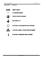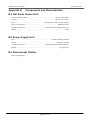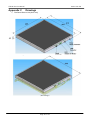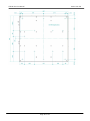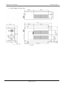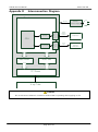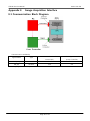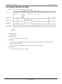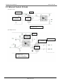
1
Digital Imaging System
TFlatXR
Service Manual
(For veterinary use)
Vieworks Co., Ltd.
2010/05/27
Manufacturer : Vieworks Co., Ltd.
#604, Suntechcity 2, 307-2, Sangdaewon-dong Jungwon-gu
Seongnam-city Gyeonggi-do, 462-806, South Korea
TEL : +82-70-7011-6161 FAX : +82-31-737-4954
[email protected] / www.vieworks.com
TFlatXR Service Manual
RA21-093-002
Revision History
Rev 0.0
27 Mar. 2010
first release (Draft)
Page 2 of 53
TFlatXR Service Manual
RA21-093-002
Accident Reporting
The FDA Medical Device Reporting regulation, 21, CFR 803 and the CE Council Directive 93/42/EEC
concerning Medical Devices require that “the manufacturer of medical devices submit a report to the
FDA or Local competent authorities whenever he becomes aware of information that reasonably
suggests that one of his installed devices:
● may have caused or contributed to a death or serious injury, or
● has malfunctioned and, if the malfunction recurs, is likely to cause or contribute to a death or serious
injury.
In order for Vieworks to comply with these requirements, all users of this equipment, operators and
service technicians, are required to provide the Quality Assurance Manager at Vieworks with the
following information regarding all reportable events as soon as possible:
1) Identification of the model and serial number.
2) Description of the event including whether any serious injury or death has been occurred.
3) Identification of the person who is submitting the information including phone number and fax
number if available.
Reference to standards
IEC/EN/UL 60601-1
Medical electrical equipment
CSA C22.2 No. 601.1
Part 1: general requirements for safety
KFDA No. 2009-1377
EN60601-1-1
Medical electrical equipment
Part 1: General requirement for the safety Collateral standard:
Safety requirement for medical electrical systems
IEC/EN 60601-1-2
Medical electrical equipment
Part 2: electromagnetic compatibility–requirements and tests
Authorized representatives
If you have any accident, please contact the authorized representatives
Page 3 of 53
TFlatXR Service Manual
RA21-093-002
Table of Contents
Revision History ............................................................................................................................................................ 2
Accident Reporting....................................................................................................................................................... 3
Reference to standards ............................................................................................................................................... 3
Authorized representatives ........................................................................................................................................ 3
Table of Contents .......................................................................................................................................................... 4
1. Safety ........................................................................................................................................................................... 7
1.1 Safety Guidelines ................................................................................................................................................... 7
1.2 General Hazards ..................................................................................................................................................... 8
1.2.1 Radiation hazards ....................................................................................................................................... 8
1.2.2 Electric shock hazard ................................................................................................................................. 8
1.2.3 Explosion Hazard ........................................................................................................................................ 8
1.2.4 Implosion Hazard ....................................................................................................................................... 8
1.3 Owner’s Responsibility ......................................................................................................................................... 8
1.4 System Diagnostic ................................................................................................................................................. 9
1.5 Calibration................................................................................................................................................................ 9
1.6 Distances measurements ..................................................................................................................................... 9
1.7 Left/Right Marker ................................................................................................................................................ 10
1.8 Images Back-up .................................................................................................................................................... 10
1.9 User Limitations ................................................................................................................................................... 10
1.10 Cleaning the system ......................................................................................................................................... 10
1.11 Overheating ......................................................................................................................................................... 10
1.12 Electrical fire ....................................................................................................................................................... 10
1.13 EMI/EMC Precaution ......................................................................................................................................... 11
1.14 EMC Information ............................................................................................................................................... 11
1.15 Maintenance precautions ................................................................................................................................ 15
1.16 Disposal ................................................................................................................................................................ 15
1.17 Changing Fuse .................................................................................................................................................... 15
1.18 Others ................................................................................................................................................................... 15
1.19 Appropriation ..................................................................................................................................................... 15
1.20 Using together with other equipment ........................................................................................................ 15
1.21 Classification (UL) .............................................................................................................................................. 15
1.22 Installation and Maintenance ......................................................................................................................... 16
2. System Description ................................................................................................................................................ 17
2.1 Intended use ......................................................................................................................................................... 17
2.2 System components ............................................................................................................................................ 17
2.3 Environment .......................................................................................................................................................... 18
Page 4 of 53
TFlatXR Service Manual
RA21-093-002
2.4 Component description ..................................................................................................................................... 18
2.5 Others ..................................................................................................................................................................... 18
3. System Specification ............................................................................................................................................. 19
3.1 Pixel Matrix ........................................................................................................................................................... 19
3.2 Effective field of view (FOV) size .................................................................................................................... 19
3.3 X-ray detection method ..................................................................................................................................... 19
3.4 Time of capture and transmission .................................................................................................................. 19
3.5 Image Specification ............................................................................................................................................. 19
3.6 Resolution .............................................................................................................................................................. 19
3.7 Electrical Specification ........................................................................................................................................ 19
3.7.1 Flat Panel Sensor Unit ............................................................................................................................. 19
3.7.2 Power Supply Unit .................................................................................................................................... 19
3.8 Interface ................................................................................................................................................................. 20
3.9 Image Acquisition Mode Table ........................................................................................................................ 20
4. System Installation................................................................................................................................................. 21
4.1. Introduction.......................................................................................................................................................... 21
4.1.1 Objective ..................................................................................................................................................... 21
4.1.2 Definitions, Abbreviations and Shortened Forms ........................................................................... 21
4.2 Before Getting Started ....................................................................................................................................... 21
4.2.1 Environmental conditions ...................................................................................................................... 21
4.2.2 Operating environments ......................................................................................................................... 21
4.2.3 Wiring for the D-Sub pin ....................................................................................................................... 21
4.2.4 Ethernet environments ............................................................................................................................ 21
4.3 Installing Housing in Apparatus ...................................................................................................................... 21
4.4 Sensor Unit Installation ...................................................................................................................................... 22
4.5 Dongle Key Installations .................................................................................................................................... 23
4.6 QXvue Installation ............................................................................................................................................... 23
4.7 Sensor unit specific files installation .............................................................................................................. 26
4.8 FPI Start .................................................................................................................................................................. 26
5. Preparation for operating TFlatXR system ..................................................................................................... 27
5.1 Select Number of Detector and Detector type ........................................................................................... 27
5.2 General Configuration of QXvue ..................................................................................................................... 28
5.3 Diagnosis and calibration .................................................................................................................................. 28
5.4 DICOM Configuration of QXvue ...................................................................................................................... 28
6. Calibration ................................................................................................................................................................ 29
6.1 Description of tabs and dialogs ...................................................................................................................... 29
6.1.1 Set configuration tab .............................................................................................................................. 29
6.1.2 Initialization tab ........................................................................................................................................ 30
6.2 Preparation for Calibration ............................................................................................................................... 32
Page 5 of 53
TFlatXR Service Manual
RA21-093-002
6.3 Configure ............................................................................................................................................................... 33
6.4 Initialization ........................................................................................................................................................... 33
6.5 Calibration.............................................................................................................................................................. 33
7. QXvue Configuration ............................................................................................................................................ 34
7.1 What is Configuration? ...................................................................................................................................... 34
7.2 General parameter setting ................................................................................................................................ 34
7.2.1 Hospital information ............................................................................................................................... 35
7.2.2 Number of Detector ................................................................................................................................ 35
7.2.3 Detector type ............................................................................................................................................. 35
7.2.4 TFlatXR Option(Dev0) .............................................................................................................................. 35
7.2.5 Detector direction compensation ........................................................................................................ 36
7.2.6 Thumbnail tab information.................................................................................................................... 36
7.2.7 Expansion setting ..................................................................................................................................... 36
7.2.8 DICOM header info .................................................................................................................................. 36
7.2.9 Dummy fields display name .................................................................................................................. 37
7.2.10 Patient comparison condition ............................................................................................................. 37
7.2.11 File-worklist location ............................................................................................................................. 37
7.3 DICOM parameter setting ................................................................................................................................. 38
7.3.1 Worklist & PACS ....................................................................................................................................... 38
7.3.2 File-worklist ................................................................................................................................................ 39
8. Trouble Shooting .................................................................................................................................................... 40
8.1 Failure Mode ......................................................................................................................................................... 40
8.2 Check the FPI Failure .......................................................................................................................................... 41
9. WARRANTY .............................................................................................................................................................. 42
Appendix A
Symbols ............................................................................................................................................. 43
Appendix B
Components and Characteristics ................................................................................................ 44
B.1 Flat Panel Sensor Unit ........................................................................................................................................ 44
B.2 Power Supply Unit ............................................................................................................................................... 44
B.3 Dimensional Outline ........................................................................................................................................... 44
Appendix C
Drawings ........................................................................................................................................... 45
Appendix D
Interconnection Diagram .............................................................................................................. 48
Appendix E
Image Acquisition Interface ......................................................................................................... 49
E.1 Communication Block Diagram ....................................................................................................................... 49
E.2 Control Interface (D-Sub) .................................................................................................................................. 50
E.3 External Control (D-Sub) .................................................................................................................................... 51
E.4 Control Interface (Ethernet) .............................................................................................................................. 52
Appendix F
Pin Assignment ................................................................................................................................ 53
F.1 D-Sub pin (Image Acquisition Control interface) ........................................................................................ 53
F.2 Power Supply Connector .................................................................................................................................... 53
Page 6 of 53
TFlatXR Service Manual
RA21-093-002
1. Safety
1.1 Safety Guidelines
Caution
Always be alert when operating this equipment. If a malfunction occurs, do not use this
equipment until qualified personnel correct the problem.
This Product was designed and manufactured to ensure maximum safety of operation and to meet all
the safety requirements applicable to electronic medical equipment. However, anyone attempting to
operate the system must be fully aware of potential safety hazards. It should be operated and
maintained in strict compliance with the following safety precautions and operating instruments
contained herein:
1) The product should be installed, maintained and serviced according to Vieworks maintenance
procedures and by Vieworks personnel or other qualified maintenance personnel approved in writing by
Vieworks. Operation and maintenance should be done in strict compliance with the operation
instructions contained in the maintenance manuals.
2) The system, in whole or in part, cannot be modified in any way without written approval from
Vieworks.
3) Before authorizing any person to operate the system, verify that the person has read and fully
understand the Service Manual. The owner should make certain that only properly trained and fully
qualified personnel are authorized to operate the equipment. An authorized operators list should be
maintained.
4) Prevent unauthorized personnel from access to the system.
5) It is important that this Service Manual be kept at hand, studied carefully and reviewed periodically
by the authorized operators.
6) The owner should ensure continuous power supply to the system, with voltage and current according
to the product specifications. If power failures are not infrequent, a UPS (Uninterrupted Power Supply)
should be installed to avoid loss of data.
7) If the product does not operate properly or if it fails to respond to the controls described in this
manual, the operator should immediately contact Vieworks field service representative, report the
incident and await further instructions.
8) The images and calculations provided by this system are intended to be used as tools for the
competent user. They are explicitly not to be regarded as a sole incontrovertible basis for clinical
diagnosis. Users are encouraged to study the literature and reach their own professional conclusions
regarding the clinical utility of the system.
9) The user should be aware of the product specifications and of the system‟s accuracy and stability
limitations. These limitations must be considered before making any decision based on quantitative
Page 7 of 53
TFlatXR Service Manual
RA21-093-002
values, in case of doubt, please consult a Vieworks representative.
10) This product must be used only in a shielded location with a minimum RF shielding effectiveness
and, for each cable that exits the shielded locations, a minimum RF filter attenuation of shielding
effectiveness.
11) This product is intended for use by healthcare professionals only. This product may cause radio
interference or may disrupt the operation of nearby equipment. It may be necessary equipment. It may
be necessary to take mitigation measures, such as reorienting or relocating the product or shielding the
location.
1.2 General Hazards
1.2.1 Radiation hazards
This system can be interfaced to x-ray generating equipment. Be certain to follow the safety instructions
and specifications for wearing proper lead shielding when in the presence of x-ray generating
equipment.
All personnel must wear dosimeters during all phases of installation, operation and maintenance of the
system and the equipment to which it is interfaced.
1.2.2 Electric shock hazard
A three conductor AC power is supplied with this system to provide the proper electrical grounding. To
minimize the shock hazard, the power cable must be plugged into a UL-approved three-contact
electrical outlet.
Do not remove or open system covers or plugs. The internal circuits of the system use high voltages
that can cause serious injury or death from electrical shock. The operator should never be allowed to
open the panels of the system.
1.2.3 Explosion Hazard
Do not operate the equipment in the presence of flammable or explosive liquids, vapors or gases. Do
not plug in or turns on the system in hazardous substances are detected in the environment.
If flammable substances are detected after the system has been turned on, do not attempt to turn off
the system or unplug it. Evacuate and ventilate the area before turning the system off.
1.2.4 Implosion Hazard
Do not subject the system to serious mechanical shocks, as the cathode ray tube (CRT) can explode if
struck or jarred. This may result in flying pieces of glass and coating that can cause serious injury.
1.3 Owner’s Responsibility
Page 8 of 53
TFlatXR Service Manual
RA21-093-002
Caution
Do not use the system if unsafe conditions are known to exist. In case of hardware failure
that could cause hazardous conditions (smoke, fire and etc), turn the power OFF and
unplug the power cords of all subsystems.
The owner is responsible for ensuring that anyone using the system reads and understand the Service
Manual and other relevant literature, and fully understands them. Vieworks makes no representation,
however, that the act of reading this manual renders the reader qualified to operate, test and calibrate
the system.
1.4 System Diagnostic
The TFlatXRCalibration software runs a system diagnostic. Run TFlatXRCalibration software when install
system or every 1 year after installation.
If an error is detected, report detailed error to Vieworks field service representative.
Caution
The owner is responsible for ensuring that diagnostic of system is performed every
year. Do not try to use the system if system diagnostic is fail.
1.5 Calibration
To ensure the optimal performances of the system it is important to verify that system is calibrated.
Caution
The owner is responsible for ensuring that the system calibration is performed at
installation time or if the system is repaired. Do not try to use the system if system
calibration is not performed.
1.6 Distances measurements
Distances measurements in millimeters are possible only after distance calibration has been performed
using a reference object (see operation manual).
Caution
The operator is responsible for performing distance calibration with a reference object
and verifying the results of the distance calibration before taking any distance
measurements on an image.
Page 9 of 53
TFlatXR Service Manual
RA21-093-002
1.7 Left/Right Marker
The operator is responsible for the correct and clear marking on the left or right side of the image to
eliminate possible errors.
The software includes an option to mark the image with L (left) or R (right) indicator from acquisition
phase through printing and archiving. If the operator chose, for any reason, not to use L/R markers, he
must use an alternative way to eliminate any possible mistake.
1.8 Images Back-up
To avoid the possibility of losing images, which might result in patient being exposed to additional
doses of radiation, it is important to back-up the images by filming or by using the CD or DVD option.
This should be done as a routine operation for every patient.
If the hard disk of workstation is about to full, the operator should back-up images and delete the
images to make room on hard disk for new patient.
Caution
The operator is responsible for backing-up images of each patient. Do not accumulate
images in the system without having a back-up.
1.9 User Limitations
The QXvue software has the technician mode, this mode could only be operated with the inputting
PASSWORD. The technician mode should be operated by the personnel who are qualified by Vieworks.
1.10 Cleaning the system
Use only isopropyl alcohol to clean surfaces of the system. Do not use detergents or organic solvents to
clean the system. Strong detergent, and organic cleaners may damage the finish and cause structural
weakening. Do not clean the system with turning the power on.
1.11 Overheating
Do not block the ventilation ports of the detector to prevent overheating of the detector. Overheating
can cause system malfunction and damages.
1.12 Electrical fire
● This equipment is not suitable for use in the presence of a flammable an aesthetic mixture with air or
with oxygen or nitrous oxide.
● Conductive fluids that drain into the active circuit components of the system may cause short circuits
that can result in electrical fire. Therefore, do not place fluids or food on any part of the system.
Page 10 of 53
TFlatXR Service Manual
RA21-093-002
● To avoid electric shocks and burns caused by use of the wrong type of fire extinguisher, make sure
that the fire extinguisher at the site has been approved for use on electrical fires.
1.13 EMI/EMC Precaution
During installation of the system, care must be taken to prevent the potential risk of electromagnetic
interference between this equipment and other devices. The device has been tested for EMI/EMC
compliance, but interference can still occur in an electromagnetically noisy environment.
Attempt to maintain a suitable distance between electrical devices to prevent cross-interference.
1.14 EMC Information
1.14.1 Guidance and manufacturer’s declaration - electromagnetic emissions
Page 11 of 53
TFlatXR Service Manual
RA21-093-002
1.14.2 Guidance and manufacturer’s declaration - electromagnetic immunity
Page 12 of 53
TFlatXR Service Manual
RA21-093-002
1.14.3 Guidance and manufacturer’s declaration – electromagnetic immunity
The EUT is intended for use in the electromagnetic environment specified below.
The customer or the user of the EUT should assure that it is used in such an environment.
Page 13 of 53
TFlatXR Service Manual
RA21-093-002
1.14.4 Recommended separation distances between portable and mobile RF
communications equipment and the EUT
The is intended for use in an electromagnetic environment in which radiated
RF disturbances are controlled. The customer or the user of the EUT can help
Prevent electromagnetic interference by maintaining a minimum distance between portable and
mobile RF communications equipment (transmitters) and the EUT as recommended below, according
to the maximum output power of the communications equipment.
Caution
DO NOT USE THE ELECTROMAGNETIC DEVICE, SUCH AS (CELLULAR/CORDLESS)
TELEPHONES AND RADIO CONTROLLED TOYS, CLOSE TO THIS SYSTEM. OTHERWISE,
IT MAY CAUSE MALFUNCTION OF THE SYSTEM.
Page 14 of 53
TFlatXR Service Manual
RA21-093-002
1.15 Maintenance precautions
Do not open enclosures, disconnect or connect any cables or accessories. Only qualified personnel
by Vieworks can do the maintenance.
1.16 Disposal
This product contains harmful materials such as lead. Improper disposal of this product may result in
environmental contamination.
When disposing of this equipment, contact Vieworks representative. Do not dispose of any part of
this equipment without consulting a Vieworks representative first.
Vieworks does not assume any responsibility for damage resulting from disposal of this equipment
without consulting Vieworks.
1.17 Changing Fuse
Caution
For Continued Protection Against Risk of Fire, Replace Only with Same Type and rating of
Fuse. Disconnect Power Before Changing Fuse.
Use only fuse to meet the specification of the system when you replace fuse with another one.
1.18 Others
Caution
No User- Serviceable Parts Inside.
1.19 Appropriation
Caution
Don‟t make operation except for the intended purpose
The system, in whole or in part, cannot be modified in any way without written approval from
Vieworks.
1.20 Using together with other equipment
Warning: When the unit is used together with other equipment in the patient area, the equipment
shall be connected according to Standard UL 60601-1 and IEC 60601-1.
1.21 Classification (UL)
1) CLASS I EQUIPMENT
2) NO APPLIED
3) NO protection against ingress of water
Page 15 of 53
TFlatXR Service Manual
RA21-093-002
4) NOT suitable for use in the presence of a flammable an aesthetic mixture with air or with Oxide
5) Continuous operation
1.22 Installation and Maintenance
Caution
Only qualified service personnel, who have received training from Vieworks should
perform this installation and troubling shooting.
Only qualified service personnel who have received training from Vieworks should perform this
installation and trouble shooting. Calibration procedures should be performed at the system
installation time or if the x-ray generator is changed otherwise the system quality is decreased.
Page 16 of 53
TFlatXR Service Manual
RA21-093-002
2. System Description
2.1 Intended use
TFlatXR system is indicated for digital imaging solution designed for general radiographic system
for human or veterinary anatomy. It is intended to replace film or screen based radiographic systems
in all general purpose diagnostic procedures.
It controls x-ray exposure and x-ray dosage by means of interfacing with x-ray generator.
Various features of this system enable the operator to diagnose easier and faster than conventional
non-digital techniques.
Computerized window, image inversion, image processing, zooming, panning, window level
adjustment, contrast adjustment, and various features enable the operator to view diagnostic details
difficult to see using conventional non-digital techniques.
2.2 System components
TFlatXR system consists of detector, power supply unit, software and its accessories.
TFlatXR system components
Sensor Unit
16kg×1
Power Supply Unit
1kg(approx.)×1
AC Cable
1.8m×1
DC Cable (Sensor Unit – Power Supply Unit)
10m×1
D-Sub Cable
10m×1
Ethernet Cable (Crossover, 1000BASE-TX)
15m×1
Ground (GND) Cable for Sensor Unit
3m×1
Ground (GND) Cable for Power Supply Unit
3m×1
Dongle Key
1
Software
Viewer
QXvue
Configuration
QXvue_Configure
QXvue_Configure_DICOM
Calibration and Diagnostic
TFlatXRCalibration
Workstation (option)
OS
Windows XP professional
CPU
Minimum Pentium 4, 3.0 GHz
Memory
Minimum 2G Byte
Hard Disk
Minimum 80G Byte
Ethernet
Minimum 1000 Mbit/s(2EA)
Monitor
1600x1200, Color
CD Rom
CD or DVD R/W
X-ray grid (option)
10:1, 215lines/inch
Page 17 of 53
TFlatXR Service Manual
RA21-093-002
Caution
Power Supply Unit & Sensor Unit – It should be used in the Patient Environment.
AC/DC Adapter – AC/DC Adapter connected to QXR should be tested by IEC 60950-1
Power Cord Set (for US) – Type SJT or SVT, 18AWG, 3-Conductor, VW-1 125V or 250V, 10A, max 3.0m long;
One end with Hospital Grade Type, MENA 5-15P or 6-15P. Other end with appliance coupler. “CAUTION
Grounding reliability can only be achieved when the equipment is connected to an equipment receptacle marked
“Hospital Only” or “Hospital Grade”
Power Cord Set (Other Countries) – For connection to supply not in USA, make sure the power cord is the
correct type that is required in your area
2.3 Environment
Temperature
Humidity
Pressure
Under delivery and stock
Under operating
-15 ~ 55 ℃
10 ~ 90 %
(Non-Condensing)
50 ~ 106 kPa
+10 ~ 35 ℃
30 ~ 85 %
(Non-Condensing)
70 ~ 106 kPa
2.4 Component description
1) Sensor Unit
Creates X-ray image by using flat panel detector.
2) Power supply unit
Supplies DC-power to sensor unit.
3) QXvue
Software to view X-ray image.
Get image from detector, process it to ease the diagnostic, save it in database and manage it.
4) TFlatXRCalibration
Diagnostic detector and report the result. Calibrate the system.
5) QXvue_Configure & QXvue_Configure_DICOM
Configure parameters for TFlatXR Digital Imaging System
2.5 Others
Caution
Accessories and Cables provided by Vieworks should be used.
Other cables and accessories may negatively affect EMC performance.
Accessory equipment connected to the analog and digital interfaces must be certified according to
the respective EN and IEC standards (for examples, EN 60950 and IEC 60950 for data processing
equipment and EN 60601-1 and IEC 60601-1 for medical equipment). Furthermore, all
configurations shall comply with the system standards EN 60601-1-1 and IEC 60601-1-1. Anyone
who connects additional equipment to any signal input or signal output ports configures a medical
system and is therefore responsible that the system complies with the requirements of the system
standards EN 60601-1-1 and IEC 60601-1-1.
Page 18 of 53
TFlatXR Service Manual
RA21-093-002
3. System Specification
3.1 Pixel Matrix
Effective Pixel Number
3008 × 3072
Pixel pitch
143 ㎛ ×143 ㎛
3.2 Effective field of view (FOV) size
Horizontal : 430 mm(16.9")
Vertical : 439 mm(17.2")
3.3 X-ray detection method
Cesium Iodide (CsI) scintillator + Amorphous Silicon (a-Si) Photodiode
3.4 Time of capture and transmission
Shorter than 6 second
3.5 Image Specification
1) Image Format
3072(W) X 3072(H)
2) Effective Field of View
Horizontal : 430 mm(16.9")
Vertical : 439 mm(17.2")
3.6 Resolution
It should be more than 3.5 LP at the center of the detector screen.
The measure resolution, follow the below procedure.
- Locate resolution chart (Nuclear Associates Model : 07-523 or the equivalent) at the center of
the detector screen with the diagonal position.
- Line pairs that could be separated by adjusting window level are the resolution.
3.7 Electrical Specification
3.7.1 Flat Panel Sensor Unit
1) Input Voltage
DC 24V
2) Power consumption
20W
3.7.2 Power Supply Unit
1) Input Voltage
AC 100 to 240V, Single phase 50/60Hz
Page 19 of 53
TFlatXR Service Manual
RA21-093-002
2) Maximum power
60VA
3) Output power standard
DC + 24 Vdc ± 10 %
3.8 Interface
1) Image data
16 bit Digital Output Ethernet (1000BASE-T)
2) System control
Ethernet (1000BASE-T)
3) X-ray sync signal
External
3.9 Image Acquisition Mode Table
Mode
Frame rate
Binning/Non-Binning
X-ray period (ms)
Non-binning
Standard: 500
(Frame/s)
3072 lines
1(approx)
Full Scan mode
(Variable between 50 to 500)
Optional: 1000, 2300, 3200 or 4000
Page 20 of 53
TFlatXR Service Manual
RA21-093-002
4. System Installation
4.1. Introduction
4.1.1 Objective
This document describes the connection method of the X-ray Flat Panel Imager (FPI) model
FDX4343R.
4.1.2 Definitions, Abbreviations and Shortened Forms
FPI
: Flat Panel Imager (X-ray flat surface detector)
EXP_REQ
: Image acquisition (X-ray exposure) request signal. Input from the user side to the
D-Sub connector on the FPI.
EXP_OK
: Exposure-OK. Image acquisition (X-ray exposure enabled) period signal.
Outputs the X-ray exposure enabled time from the FPI. Output from the D-Sub
connector on the FPI.
4.2 Before Getting Started
4.2.1 Environmental conditions
For the operating environment, the ambient temperature is +10oC to +35oC.
For the storage environment, the ambient temperature is -15oC to +55oC.
4.2.2 Operating environments
Windows XP SP2
4.2.3 Wiring for the D-Sub pin
Wiring is required for external control. D-Sub connector pin assignment and signal names on
the side of the FPI are described below. The EXP_OK signal notifies you of the X-ray exposure
enabled timing.
4.2.4 Ethernet environments
Although the FPI system can be remote-controlled from the user-created FPI system driving
software via Ethernet, it is limited to the communication between this FPI system and user
system on a 1:1 basis. The FPI system cannot be used in the universal network environment.
Do not connect it to the universal network environment.
Followings are requirement for Ethernet.
- Ether Crossover Cable
- Ethernet (1000BASE-TX)
4.3 Installing Housing in Apparatus
Use the screw holes 16-M4 (Depth 8).
The screws should be fixed all screw holes of each part. Also, the screw thread length entering the
screw holes should be each depth of holes.
Installation respect of the device that installs FPI should be smooth.
It is necessary to clean installation respect of the device before FPI is installed.
Page 21 of 53
TFlatXR Service Manual
RA21-093-002
Tightening torque of screw; 1.35 - 1.65 [Nm]
4.4 Sensor Unit Installation
For connection, connect according to this item as shown in a figure below.
1) Connect the Ethernet terminal on the FPI and User PC via the Ether Crossover Cable. This
system requires a dedicated local line. If Internet is in use on the user PC, two lines; the Global
Ethernet that goes through the DNS server and the Local Ethernet for connecting this system, are
required. For the Ethernet line with this system, please allocate a proper address for the user PC‟s
local IP address. The local IP address of this system is 192.168.95.30 or 192.168.95.31(TBD). The IP
address of this system can be selected.
2) Connect the FPI to the X-ray generator
Please refer to “OPERATION MANUAL OF FDX4343R” for more details
3) Connect the FPI to power supply (AC-DC) via the attached power cable
4) Connect the AC power cable to the power box and connect the terminal of the attached AC
power cable to the AC power supply
Page 22 of 53
TFlatXR Service Manual
RA21-093-002
Caution
Do not disconnect Ethernet connection while DC24V is operating and supplying to FPI.
4.5 Dongle Key Installations
QXvue software checks for USB-type dongle key to run. Please plug the dongle key into any free
USB port on PC.
4.6 QXvue Installation
1) Insert QXvue CD in CD Drive
2) Run “Setup.exe” program then InstallShield Wizard will be displayed, click “Next” button
3) Input User Name and Organization, and select user, then click “Next” button
Page 23 of 53
TFlatXR Service Manual
RA21-093-002
4) Select setup type as Complete then click “Next” button
5) “Ready to Install the Program” window will be displayed, press “Install” Button
Page 24 of 53
TFlatXR Service Manual
RA21-093-002
6) “Installing QXvue” will be displayed, now the InstallShield is installing QXvue.
7) After finishing installation of QXvue, “InstallShield Wizard Completed” window will be displayed,
Then press “Finish” button.
8) The following message box will be displayed, press “Yes” button to restart computer.
Page 25 of 53
TFlatXR Service Manual
RA21-093-002
Now the QXvue software is successfully installed to the following directory.
Software
C:\Program Files\QXvue
Data
D:\QXvueData
Executable File List
QXvue.exe
Viewer program
TFlatXRCalibration.exe
Calibration program
QXvue_Configure.exe
General Configure program
QXvue_Configure_DICOM.exe
DICOM Configure program
To run QXvue, “East Asian Language” option in windows should be selected, if not ,
"Selected collating sequence not supported by the operating system" or “the selected
order is not supported by this operating system” message will be displayed.
To select this option
1. Start->Control Panel-> Regional and Language…
2. Check “Install files for East Asian languages” option and click “OK” button to
install
4.7 Sensor unit specific files installation
1) Please check the following files are included in a separately provided CD-ROM disk.
Defective pixel map: “TETD_Defect_YYYYMMSNSNSN.map”
License key code file: “YYYYMMSNSNSN.key”
2) Copy “TETD_Defect_YYYYMMSNSNSN.map” into the folder “D:\QXvueData\Reference”
3) Copy “YYYYMMSNSNSN.key” into the folder “D:\QXvueData\Config”
4.8 FPI Start
(1) Power on and boot the user PC.
(2) Check the connection between units and input the AC power to the AC power supply.
DC24V is input to the FPI and the FPI is started.
(3) If the FPI starts successfully, LED1, 2, and 3 on the side of the FPI are lit in green.
For the LED‟s, refer to 8.2
If power is turned on for the first time, the FPI starts with the settings made upon shipping from
the factory. For the second time onward, the FPI starts with the settings saved by the setting
status save command. If the settings are not saved by the setting status save command, the FPI
starts with the most recently saved settings.
Page 26 of 53
TFlatXR Service Manual
RA21-093-002
5. Preparation for operating TFlatXR system
To operate TFlatXR system, following step should be executed
1) Run QXvue_Configure
2) Select Number of Detector with one Detector and Detector type with TFlatXR-9
Supporting “Two detector” is TBD.
3) Do Configuration of general
4) Exit QXvue_Configure
5) Run TFlatXRCalibration
6) Diagnosis and calibrate
7) Exit TFlatXRCalibration
8) Run QXvue_Configure_DICOM
9) Do Configuration of DICOM
10) Exit QXvue_Configure_DICOM
5.1 Select Number of Detector and Detector type
1) Run QXvue_Configure in “C:\program files\QXvue” folder
2) Select Number of Detector and Detector type
Page 27 of 53
TFlatXR Service Manual
RA21-093-002
5.2 General Configuration of QXvue
Refer to clause 7.2
5.3 Diagnosis and calibration
Refer to clause 6 for diagnosis and clause 6 for calibration
5.4 DICOM Configuration of QXvue
Refer to clause 7.3
Page 28 of 53
TFlatXR Service Manual
RA21-093-002
6. Calibration
Calibration procedure calibrates pixel gain using the installed x-ray generator and x-ray tube.
The calibration should be performed on the following case
Detector installation
X-ray generator replacement
X-ray tube replacement
6.1 Description of tabs and dialogs
6.1.1 Set configuration tab
1) When this tab is activated
The program reads current configuration from the XML file.
2) „Next‟ button
Saves any modified configurations to the XML file.
3) Other buttons
A.
Auto Pixel Map
B.
White Image Check
C.
Dark Image Check
D.
Buttons in „Reference Step‟ group
i.
Add – Adds a reference calibration step.
ii.
Delete – Deletes selected reference calibration steps.
iii.
Move up – Moves up selected reference calibration step.
iv.
Mode down – Moves down selected reference calibration steps.
Page 29 of 53
TFlatXR Service Manual
RA21-093-002
6.1.2 Initialization tab
1) „Initialize Detector‟ button
Initializes the detector.
It may take several seconds to initialize the detector.
2) „Enter Calibration Mode‟ button
Let the detector enter calibration mode. If the detector enters calibration mode successfully, a
dialog will pop up for calibration procedures.
Page 30 of 53
TFlatXR Service Manual
RA21-093-002
6.1.3 Calibration dialog
1) „Get Calibration Step‟ button
„GetCalibrationStep‟ command is sent to the detector.
2) „Confirm Calibration Step‟ button
Finishes the current step for the calibration. „ConfirmCalibrationStep‟ command is sent to the
detector.
3) „Complete Calibration‟ button
Completes the calibration procedures. „CompleteCalibrationStep‟ command is sent to the
detector. Also „ExitCalibrationMode‟ command is called. This command let the detector enter the
intial state. The dialog will be closed.
4) „Cancel Calibration‟ button
Cancels out whole calibration procedures. „AbortCalibration‟ is sent to the detector
Also „ExitCalibrationMode‟ command is called. This command let the detector enter the intial
state. The dialog will be closed.
5) Other buttons
A.
Select – Enters the region selection mode. To select region to see statistics of the rigion in
„Information‟ dialog, this mode should be selected.
B.
Fit – Adjust the size of image to fit in the image display area.
C.
ROI Pickup – If you select a region in this mode, W/L is adjusted according to the pixel
values in the region.
D.
PAN – Enters the mode adjusting the image position in the display area.
E.
ZOOM – Enters the mode enlarging or shrinking the image size.
F.
W/L – Enters the mode adjusting W/L(Window/Level). W/L can be adjusted by dragging the
mouse with right mouse button pressed at any time.
G.
100%, 200%, 400%, 800%, 1600% - Adjusts the image size as the selected ratio.
Page 31 of 53
TFlatXR Service Manual
H.
RA21-093-002
Open Information
The dialog displays statistics of the selected region or pixel level of the pixel where the cursor is
pointing. If you select the „Statistics‟ from the Combo box, the former is displayed. If you select
the „Pixel‟ from the Combo box, the latter is displayed.
To select a region by dragging the mouse, „Select‟ mode should be selected as current mode. Or
you can select a region by putting coordinates in the edit boxes and clicking „update button‟.
i.
Center 50X50 – displays statics of the 50 by 50 wide rectangular region located at the
center of the image.
ii.
Center 100X100 – displays statics of the 100 by 100 wide rectangular region located at
the center of the image.
iii.
Whole area – displays statistics of the whole image.
6.2 Preparation for Calibration
- Run Calibration software
- Set SID to 1.8m or 1m.
Caution
Do not use x-ray grid when do calibration.
Page 32 of 53
TFlatXR Service Manual
RA21-093-002
6.3 Configure
Select options referring to 6.1.1 clause and adds/removes/modifies calibration steps.
6.4 Initialization
Initialize the detector by clicking „Initialize Detector‟ button. It takes several seconds to initialize the
detector. If the initialization is done, „Enter Calibration Mode‟ button is enabled. By clicking „Enter
Calibration Mode‟ button, you can let the detector enter the calibration mode. If the detector
successfully enters the calibration mode, a „Calibration‟ dialog will pop up.
6.5 Calibration
If the „Calibration‟ dialog is displayed, this means that the detector successfully has entered the
calibration mode.
The procedures of calibration are as follows.
1) Get Calibration Step – gets information for current calibration step.
2) Exposure & Check real DV – After taking the image, you should adjust SID, KVP and mAs to make
the value „Current DV‟ close to the value „Target DV‟. A couple of more shots should be made to get
an appropriate „Current DV‟ value.
3) Confirm Calibration Step – If you succeeded in getting the desired „Current DV‟ value in step 0,
click „Confirm Calibration Step‟ to finish the current calibration step.
4) Repeat 1)~3) until the necessary number of calibration steps has been executed.
5) Complete Calibration – If the necessary number of calibration steps has been executed, „Complete
Calibration‟ button will be enabled. By clicking the „Complete Calibration‟ button, you can complete
the calibration process.
Page 33 of 53
TFlatXR Service Manual
RA21-093-002
7. QXvue Configuration
7.1 What is Configuration?
Using configuration software we can set the various parameters that are used in the QXvue, so the
proper setting of parameter is important.
Configuration of QXvue is needed when the TFlatXR is installed, and this job should be performed
before using QXvue.
Configuration of QXvue is consist of two parts
General parameter setting by QXvue_Configure : Basic information used by QXvue
DICOM parameter setting by QXvue_Configure_DICOM : Worklist related DICOM header setting
The configuration software is located at “C:\program files\QXvue” folder
7.2 General parameter setting
Page 34 of 53
TFlatXR Service Manual
RA21-093-002
7.2.1 Hospital information
- They are the name, address and telephone number of the hospital in which the QXR system is
installed.
- The values of the name field and address field is put into the „institution name‟ tag and „institution
address‟ tag respectively when creating DCM files.
7.2.2 Number of Detector
- Select “One Detector”
- Supporting “Two detector” is TBD.
7.2.3 Detector type
- Select TFlatXR-9
7.2.4 TFlatXR Option(Dev0)
- IP Address : The IP address of FPI
“192.168.95.30” or “192.168.95.31”(TBD)
Note
FPI address is fixed with “192.168.95.30”. “192.168.95.31” is not available now.
PC‟s network setting has to be changed with same class of FPI address for crossconnection.
Ex) IP Address : 192.168.95.10
Basic Gateway : 192.168.95.1
- Saturation Value :
The Saturation value for digital value
“11000”(default)
- XRay Appliable Time : “9” (default)
Note
0: 50ms, 1: 100ms, 2: 150ms, 3: 200ms, 4: 250ms, 5: 300ms, 6: 350ms,
7: 400ms, 8: 450ms, 9: 500ms, 19: 1000ms, 45: 2300ms, 63: 3200ms,
79: 4000ms ,others: 500 milli-second
- Correction Type : “7” (default)
Note
0:
1:
3:
7:
without any correction,
Only apply offset correction
apply offset and gain correction
Apply offset, gain, bad pixel correction
Page 35 of 53
TFlatXR Service Manual
RA21-093-002
7.2.5 Detector direction compensation
This is used to set the image direction
Set direction according to installed state of detector
CW : 0
CCW : 0
H-Mirror : 1
V-Mirror : 0
CW : 0
CCW : 0
H-Mirror : 0
V-Mirror : 1
CW : 1
CCW : 0
H-Mirror : 0
V-Mirror : 1
CW : 1
CCW : 0
H-Mirror : 1
V-Mirror : 0
7.2.6 Thumbnail tab information
- Select the item(s) to be displayed in the thumbnail tab.
- Patient ID and Patient name is default and the additional information can be displayed in the
thumbnail tab according to the setting
7.2.7 Expansion setting
If the Minimize Button check box is set, you will have the Minimize button above the „Exit‟ button.
7.2.8 DICOM header info
1) Detector Unique Number
- The 12-digit number unique for each detector which constitutes „Study Instance UID‟, „Series
Instance UID‟ and „SOP Instance UID‟
- If you run QXvueCalibration, the field is automatically filled in.
2) TAG_STATION_NAME
Page 36 of 53
TFlatXR Service Manual
RA21-093-002
- A string for „station name‟ tag
- This is used to distinguish the detectors if two or more detectors are installed in the same
hospital
7.2.9 Dummy fields display name
- Dummy field is used for the connection with the worklist server
- If the worklist server sends some information that is not mentioned in the DICOM standard, then
QXvue can receive that information using dummy fields
- Dummy field will be displayed as set name in the order list
7.2.10 Patient comparison condition
- QXvue distinguishes among patients by comparing the selected fields of patients when inserting
the patients from the worklist server into the local patient list database
- When we query study order from the worklist server, if all selected patient comparison field data is
equal to already registered order, QXvue ignore that study order
- If none of comparison field is select, then Patient ID will be used as comparison field
- If any comparison field is selected than only the selected field will be used as comparison field
7.2.11 File-worklist location
- If worklist server is not available and the PACS system is providing order using text file QXvue can
receive patients list from that file
- QXvue check assigned folder and if there is new order file QXvue will load study order from that
file and after loading, QXvue will delete that file
Page 37 of 53
TFlatXR Service Manual
RA21-093-002
7.3 DICOM parameter setting
QXvue use internally defined tag name related patient information for DICOM, this information will
be filled when we register patient or receive study order from the worklist server.
After x-ray exposure these information will be stored to the internal database and will be put to the
DICOM file as DICOM tag when we make DICOM file.
When QXvue receive order from the worklist server that might not be the standard DICOM tag, so
QXvue has DICOM tag converting function to make standard DICOM file.
7.3.1 Worklist & PACS
1) Definition
- Incoming : Receiving tag from the worklist server
- Internal
: Internally defined field name of the patient information and study order in QXvue
- Outgoing : DICOM tag that will be stored to DICOM file
2) Worklist Matching
- Select internal field name then currently matched tag will be displayed in the items table.
- Select incoming tag from the list and register it by clicking “<<” button
- Select outgoing tag from the list and register it by clicking “>>” button
Page 38 of 53
TFlatXR Service Manual
RA21-093-002
7.3.2 File-worklist
- The format of file worklist should be text file and the field should be separated by delimiter
- The delimiter is user-defined and should be registered in the “delimiter” table
- Internally defined fields for patient information and study order is listed in the “internal field” table
- Set the matching internal field name according to the text order in the worklist file
- Internal field will be translated to the DICOM tag set at 3.1.2
- The delimiter could be one or more characters.
- The date and time format used in worklist file can be selected, and all characters located in the
place of where star-closure (*) exists is ignored.
<Date format>
YYYY : Year represented by full four digits
MM : Month as digits with leading zero for single-digit months
DD : Day of month as digits with leading zero for single-digit days
<Time Format>
HH : Hours with leading zero for single-digit hours; 24-hour clock
MM : Minutes with leading zero for single-digit minutes
SS : Seconds with leading zero for single-digit seconds
Page 39 of 53
TFlatXR Service Manual
RA21-093-002
8. Trouble Shooting
Note :
Trouble shooting must be performed by technician who is trained by the Vieworks Co., Ltd or an
organization certified by Vieworks Co., Ltd.
If an unqualified person performs troubleshooting on the system resulting in damaging the
detector, software or hardware, then the Vieworks Co. or its representative is not responsible for
the detector repair even if the warranty is not expired.
* Please refer to the warranty section 9 of this manual for more details.
8.1 Failure Mode
Failure Mode
Repairing Procedure
LED is not lit
Refer to 8.2
Page 40 of 53
TFlatXR Service Manual
RA21-093-002
8.2 Check the FPI Failure
Explanation of details on LED‟s on the side of the FPI
<LED1 POWER – Green>
Lit in green: When +24V is input
<LED2 HEALTHY – Green>
Lit in green: FPI retains the normal status.
<LED3 NETWORK – Green>
Lit in green: Normal communication status
<LED4 IMAGING – Green>
Lit in green, Radiography status, EXP_OK output period
Lit in green: READOUT
Page 41 of 53
TFlatXR Service Manual
RA21-093-002
9. WARRANTY
Vieworks Co. warrants that this product will be free from defects in materials and workmanship for a
period of twelve (12) months from the date of delivery. If any such product proves defective during
this warranty period, Vieworks Co., at its option, either will repair the defective product without
charge for parts and labor, or will provide a replacement in exchange for the defective product. In
order to obtain service under this warranty, Customer must notify Vieworks Co. of the defect before
the expiration of the warranty period and make suitable arrangements for the performance of
service. Customer shall be responsible for packaging and shipping the defective product to the
service center designated by Vieworks Co. with shipping charges prepaid. Vieworks Co. shall pay for
the return of the product to Customer if the shipment is to a location within the country in which
the Vieworks Co. designated service center is located. Customer shall be responsible for paying all
shipping charges, duties, taxes, and any other charges for products returned to any other locations.
This warranty shall not apply to any defect, failure, or damage caused by improper or inadequate
maintenance and care. Vieworks shall not be obligated to furnish service under this warranty to
repair damage resulting from attempts by personnel other than Vieworks Co.; or its representatives
to install, repair, or service this product, to repair damage resulting from improper use or connection
to incompatible equipment or power source; or to service a product that has been modified or
integrated with other products when the effect of such modification or integration increases the
time or difficulty of servicing the product.
THIS WARRANTY IS GIVEN BY VIEWORKS CO. WITH RESPECT TO THIS PRODUCT IN
LIEU OF ANY OTHER WARRANTIES, EXPRESS OR IMPLIED. VIEWORKS CO. AND ITS
VENDOR DISCLAIM ANY IMPLIED WARRANTIES OF MERCHANTABLILITY OR
FITNESS FOR A PARTICULAR PURPOSE. VIEWORKS CO. RESPONSIBILITY TO REPAIR
OR REPLACE DEFECTIVE PRODUCTS IS THE SOLE REMEDY PROVIDED TO THE
CUSTOMER FOR BREACH OF THIS WARRANTY. VIEWORKS AND ITS VENDORS WILL
NOT BE LIABLE FOR ANY INDIRECT, SPECIAL, INCIDENTAL, OR CONSEQUENTIAL
DAMAGES IRRESPECTIVE OF WHETHER VIEWORKS CO. OR THE VENDOR HAS
ADVANCE NOTICE OF THE POSSIBILITY OF SUCH DAMAGES.
There are no warranties which extend beyond the description mentioned in this document.
Page 42 of 53
TFlatXR Service Manual
Appendix A
RA21-093-002
Symbols
DIRECT CURRENT
~
ALTERNATING CURRENT
PROTECTIVE EARTH (GROUND)
EQUIPOTENTIALITY
OFF (POWER : DISCONNECTION FROM THE MAINS)
ATTENTION, CONSULT ACCOMPANYING DOCUMENS
ON (POWER : CONNECTION FROM THE MAINS)
Page 43 of 53
TFlatXR Service Manual
Appendix B
RA21-093-002
Components and Characteristics
B.1 Flat Panel Sensor Unit
Sensor Protection Plate .................................................................................. Carbon Fiber Plate
Cooling ................................................................................................................. Natural Air Cooling
Input ...................................................................................... DC24V (from AC/DC Power Supply)
Power Consumption ................................................................................................ Maximum 20W
Overall Dimensions ............................................................ 512×495×43mm (W(H)×D(V)×H))
Weight ............................................................................................................................................... 16 kg
B.2 Power Supply Unit
Input ............................................................................................................. AC100 to 240V, 50/60Hz
Output ........................................................................................................................ DC24V 1.3A 60W
Overall Dimensions ............................................................ 126×200×60mm (W(H)×D(V)×H))
Weight .............................................................................................................................. 1 kg (approx.)
B.3 Dimensional Outline
Refer to Appendix C
Page 44 of 53
TFlatXR Service Manual
Appendix C
RA21-093-002
Drawings
1) Flat Panel Sensor Unit (Unit: mm)
(Wired Image)
Page 45 of 53
TFlatXR Service Manual
RA21-093-002
Page 46 of 53
TFlatXR Service Manual
RA21-093-002
2) Power Supply Unit (Unit: mm)
Page 47 of 53
TFlatXR Service Manual
Appendix D
RA21-093-002
Interconnection Diagram
Detector
Control Board
DC 24V
Ethernet
module
Ethernet
Connector
I/O module
D-Sub
connector
CPU
Gate Driver
Image
Data &
Control
X-ray
Sync
AC/DC
Power Supply
PC(User)
X-ray
Control
Unit(User)
ROIC Unit
TFT Panel
X-ray
X-ray Tube
Caution
Do not disconnect Ethernet connection while DC24V is operating and supplying to FPI.
Page 48 of 53
TFlatXR Service Manual
Appendix E
RA21-093-002
Image Acquisition Interface
E.1 Communication Block Diagram
Communication Availability
Ethernet Command
D-Sub Signal Control
Control (PC)
(X-ray Controller)
INPUT
OK
OK
OUTPUT
N.A
OK
Signal Name
Type
EXP_REQ
EXP_OK
*EXP_REQ Command Response
Page 49 of 53
TFlatXR Service Manual
RA21-093-002
E.2 Control Interface (D-Sub)
D-Sub Signal Control Interface Operation Sequence
A: EXP_REQ width
Minimum 1ms
B: Refresh period
For line drive (3072 Line scan), 36.9ms
C: EXP period
Set value: see the Image Acquisition mode table (50 to 500ms, 1000ms, 2300ms, 3200ms &
4000ms, Standard 500ms)
When you want to change EXP period, put in some period Command.
D: Read period
For line drive (3072 Line Scan) 1222ms
Page 50 of 53
TFlatXR Service Manual
RA21-093-002
E.3 External Control (D-Sub)
(1) Input circuit
User system side
High : 4.0V(min.)
Low : 0.8V(max.)
FPI side
D-Sub 9pin
connector
Z1 : EZJZ1V120KA, Matsushita
U1: PS2801-1, NEC
(2) Output circuit
FPI side
Isolated DC
–DC module
User system side
High : 4.0V(min.)
5mA(max.)
D-Sub 9pin
connector
Z1 : EZJZ1V120KA, Matsushita
UI : PS2801-1, NEC
Q1 : 2SC4081T106Q, ROHM
U2 : COSEL, SUCS1R50505BP
Page 51 of 53
TFlatXR Service Manual
RA21-093-002
E.4 Control Interface (Ethernet)
Ethernet Interface Command Control Operation Sequence
①:EXP_REQ-EXP_OK period Maximum 40ms
②:EXP_REQ-DATA STORAGE period Maximum 2,000ms (case EXPOSURE 500ms)
③:POWER ON-EXP_REQ period Minimum 520ms
Description of the sequence
■ By receiving “EXP_REQ” during “Refresh” status, proceeds to “Exposure” after completion of
“Refresh”.
■ Continues “EXP_OK” signal ON during “Exposure”. ON period is defined by Image Acquisition
mode table.
■ Proceeds to “Data Read” after completion of Exposure.
■ After “Read”, FPI proceeds to status of “Refresh”.
Page 52 of 53
TFlatXR Service Manual
Appendix F
RA21-093-002
Pin Assignment
F.1 D-Sub pin (Image Acquisition Control interface)
Number viewed from insertion port side
D-Sub connector pin assignment on the side of the FPI.
F.2 Power Supply Connector
Page 53 of 53