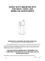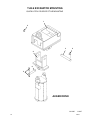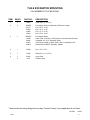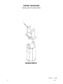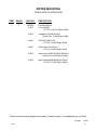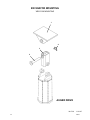
1
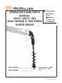
OPERATOR’S AND PARTS
MANUAL
X6075 / X8075 / 8K2
HIGH TORQUE & TWO SPEED
AUGER DRIVES
SERIAL NUMBER: ___________________
MODEL NUMBER: ___________________
800-456-7100 I www.paladinlcg.com
Manual Number: OM723
Part Number: 75623
Rev. 503 Gay Street, Delhi, IA 52223, United States of America
M-1644
1-25-10-2
TABLE OF CONTENTS
X6075, X8075 & 8K2 AUGER DRIVES
PREFACE...........................................................................................................................................................3
SAFETY PRECAUTIONS
SAFETY STATEMENTS............................................................................................................................ 5
GENERAL SAFETY PRECAUTIONS.....................................................................................................5-7
EQUIPMENT SAFETY PRECAUTIONS................................................................................................... 8
INSTALLATION........................................................................................................................................... 9-11
HYDRAULIC SYSTEM HOOK-UP INSTRUCTIONS.......................................................................... 12
OPERATING INSTRUCTIONS.............................................................................................................13-14
maintenance
lubrication......................................................................................................................................... 15
DAILY INSPECTION............................................................................................................................... 15
PLANETARY GEARBOX......................................................................................................................... 16
STORAGE PROCEDURE....................................................................................................................... 16
PLANETARY GEAR REDUCTION SERVICE PARTS............................................................................. 17
OPTIONS
AUGER OPTIONS..............................................................................................................................18-20
AUGER WEAR PARTS......................................................................................................................20-21
TROUBLESHOOTING................................................................................................................................. 22
specifications......................................................................................................................................... 23
limited warranty.................................................................................................................................. 25
PARTS
X6075 AUGER DRIVE ASSEMBLY....................................................................................................26-27
X8075 AUGER DRIVE ASSEMBLY....................................................................................................28-29
8K2 auger drive assembly........................................................................................................30-31
Replacement parts - 8k2 hydraulic valve........................................................................32-33
heavy duty mounting kits
TLB & EXCAVATOR MOUNTING - QUICK HITCH COUPLER STYLE.............................................36-37
SKID STEER LOADER MOUNTING..................................................................................................38-39
TLB & EXCAVATOR - PIN GRABBER/PIN ON STYLE - PIVOT MOUNTING...................................40-41
DIPPER MOUNTING - PENDULUM STYLE......................................................................................42-43
EXCAVATOR WELD ON MOUNTING................................................................................................44-45
M-1737
75623
2-21-08
1
THIS PAGE
IS INTENTIONALLY
BLANK
2
75623
PREFACE
GENERAL COMMENTS
Congratulations on the purchase of your new McMillen product! This product was carefully designed and manufactured to give you many years of dependable service. Only minor
maintenance (such as cleaning and lubricating) is required to keep it in top working condition.
Be sure to observe all maintenance procedures and safety precautions in this manual and on
any safety decals located on the product and on any equipment on which the attachment is
mounted.
This manual has been designed to help you do a better, safer job. Read this manual
carefully and become familiar with its contents. WARNING! Never let anyone operate this unit without reading the "Safety Precautions"
and "Operating Instructions" sections of this manual.
Always choose hard, level ground to park the vehicle on and set the brake
so the unit cannot roll.
Unless noted otherwise, right and left sides are determined from the operator’s control
position when facing the attachment.
NOTE: The illustrations and data used in this manual were current (according to the
information available to us) at the time of printing, however, we reserve the right to redesign and change the attachment as may be necessary without notification.
BEFORE OPERATION
The primary responsibility for safety with this equipment falls to the operator. Make
sure the equipment is operated only by trained individuals that have read and understand this
manual. If there is any portion of this manual or function you do not understand, contact your
local authorized dealer or the manufacturer.
SAFETY ALERT SYMBOL
This is the "Safety Alert Symbol" used by this industry. This symbol is used to
warn of possible injury. Be sure to read all warnings carefully. They are included
for your safety and for the safety of others working with you.
SERVICE
When servicing your product, remember to use only manufacturer replacement parts. Substitute parts may not meet the standards required for safe, dependable operation.
To facilitate parts ordering, record the model and serial number of your unit in the space
provided on the cover of this manual. This information may be obtained from the identification
plate located on the product.
The parts department needs this information to insure that you receive the correct parts
for your specific model.
M-1643 10-18-07
75623
3
THIS PAGE
IS INTENTIONALLY
BLANK
4
75623
SAFETY STATEMENTS
THIS SYMBOL BY ITSELF OR WITH A WARNING WORD THROUGHOUT THIS MANUAL IS USED TO CALL YOUR ATTENTION TO INSTRUCTIONS INVOLVING YOUR
PERSONAL SAFETY OR THE SAFETY OF OTHERS. FAILURE TO FOLLOW THESE
INSTRUCTIONS CAN RESULT IN INJURY OR DEATH.
DANGER
THIS SIGNAL WORD IS USED WHERE SERIOUS INJURY OR DEATH
WILL RESULT IF THE INSTRUCTIONS ARE NOT FOLLOWED PROPERLY.
WARNING
THIS SIGNAL WORD IS USED WHERE SERIOUS INJURY OR DEATH
COULD RESULT IF THE INSTRUCTIONS ARE NOT FOLLOWED PROPERLY.
CAUTION
THIS SIGNAL WORD IS USED WHERE MINOR INJURY COULD RESULT IF
THE INSTRUCTIONS ARE NOT FOLLOWED PROPERLY.
NOTICE
NOTICE INDICATES A PROPERTY DAMAGE MESSAGE.
GENERAL SAFETY PRECAUTIONS
WARNING!
READ MANUAL PRIOR TO INSTALLATION
Improper installation, operation, or maintenance of this equipment could result in serious injury or death. Operators and maintenance personnel should read this manual,
as well as all manuals related to this equipment and the prime mover thoroughly
before beginning installation, operation, or maintenance. FOLLOW ALL SAFETY
INSTRUCTIONS IN THIS MANUAL AND THE PRIME MOVER’S MANUAL(S).
READ AND UNDERSTAND ALL SAFETY STATEMENTS
Read all safety decals and safety statements in all manuals prior to operating or
working on this equipment. Know and obey all OSHA regulations, local laws, and
other professional guidelines for your operation. Know and follow good work practices when assembling, maintaining, repairing, mounting, removing, or operating this
equipment.
KNOW YOUR EQUIPMENT
Know your equipment’s capabilities, dimensions, and operations before operating.
Visually inspect your equipment before you start, and never operate equipment that
is not in proper working order with all safety devices intact. Check all hardware to
ensure it is tight. Make certain that all locking pins, latches, and connection devices
are properly installed and secured. Remove and replace any damaged, fatigued, or
excessively worn parts. Make certain all safety decals are in place and are legible.
Keep decals clean, and replace them if they become worn or hard to read.
M-806
75623
7-28-05-2
5
GENERAL SAFETY PRECAUTIONS
WARNING!
PROTECT AGAINST FLYING DEBRIS
Always wear proper safety glasses, goggles, or a face shield when driving pins in or
out, or when any operation causes dust, flying debris, or any other hazardous material.
WARNING!
LOWER OR SUPPORT RAISED EQUIPMENT
Do not work under raised booms without supporting them. Do not use support material made of concrete blocks, logs, buckets, barrels, or any other material that could
suddenly collapse or shift positions. Make sure support material is solid, not decayed, warped, twisted, or tapered. Lower booms to ground level or on blocks. Lower
booms and attachments to the ground before leaving the cab or operator’s station.
WARNING!
USE CARE WITH HYDRAULIC FLUID PRESSURE
Hydraulic fluid under pressure can penetrate the skin and cause serious injury or
death. Hydraulic leaks under pressure may not be visible. Before connecting or disconnecting hydraulic hoses, read your prime mover’s operator’s manual for detailed
instructions on connecting and disconnecting hydraulic hoses or fittings.
•
•
•
Keep unprotected body parts, such as face, eyes, and arms as far away as
possible from a suspected leak. Flesh injected with hydraulic fluid may develop
gangrene or other permanent disabilities.
If injured by injected fluid, see a doctor at once. If your doctor is not familiar with
this type of injury, ask him or her to research it immediately to determine proper
treatment.
Wear safety glasses, protective clothing, and use a piece of cardboard or wood
when searching for hydraulic leaks. DO NOT USE YOUR HANDS! SEE ILLUSTRATION.
CARDBOARD
HYDRAULIC HOSE
OR FITTING
MAGNIFYING GLASS
M-807 7-28-05-2
6
75623
GENERAL SAFETY PRECAUTIONS
WARNING!
DO NOT MODIFY MACHINE OR ATTACHMENTS
Modifications may weaken the integrity of the attachment and may impair the function, safety, life, and performance of the attachment. When making repairs, use only
the manufacturer’s genuine parts, following authorized instructions. Other parts may
be substandard in fit and quality. Never modify any ROPS (Roll Over Protection
Structure) or FOPS (Falling Object Protective Structure) equipment or device. Any
modifications must be authorized in writing by the manufacturer.
WARNING!
SAFELY MAINTAIN AND REPAIR EQUIPMENT
•
•
•
•
•
Do not wear loose clothing or any accessories that can catch in moving parts. If
you have long hair, cover or secure it so that it does not become entangled in the
equipment.
Work on a level surface in a well-lit area.
Use properly grounded electrical outlets and tools.
Use the correct tools for the job at hand. Make sure they are in good condition for
the task required.
Wear the protective equipment specified by the tool manufacturer.
SAFELY OPERATE EQUIPMENT
Do not operate equipment until you are completely trained by a qualified operator
in how to use the controls, know its capabilities, dimensions, and all safety requirements. See your machine’s manual for these instructions.
• Keep all step plates, grab bars, pedals, and controls free of dirt, grease, debris,
and oil.
• Never allow anyone to be around the equipment when it is operating.
• Do not allow riders on the attachment or the prime mover.
• Do not operate the equipment from anywhere other than the correct operator’s
position.
• Never leave equipment unattended with the engine running, or with this attachment in a raised position.
• Do not alter or remove any safety feature from the prime mover or this attachment.
• Know your work site safety rules as well as traffic rules and flow. When in doubt
on any safety issue, contact your supervisor or safety coordinator for an explanation.
M-808 7-28-05-2
75623
7
EQUIPMENT SAFETY PRECAUTIONS
WARNING! KNOW WHERE UTILITIES ARE
Observe overhead electrical and other utility lines. Be sure equipment will clear them.
When digging, call your local utilities for location of buried utility lines, gas, water, and
sewer, as well as any other hazard you may encounter.
OPERATING THE PRIME MOVER
Avoid steep hillside operation, which could cause the prime mover to overturn. Consult
your prime mover operator’s and safety manuals for maximum incline allowable.
EXPOSURE TO RESPIRABLE CRYSTALLINE SILICA DUST ALONG
WITH OTHER HAZARDOUS DUSTS MAY CAUSE SERIOUS OR
FATAL RESPIRATORY DISEASE.
It is recommended to use dust suppression, dust collection and if necessary, personal
protective equipment during the operation of any attachment that may cause high levels
of dust.
WORKING WITH THE AUGER
• All bystanders should be kept a minimum of 10 feet (3 meters) away from the working
area of the earth auger.
• An operator must not use drugs or alcohol, which can change his or her alertness or
coordination. An operator taking prescription or over-the-counter drugs should seek
medical advice on whether or not he or she can safely operate equipment.
• Before exiting the prime mover, lower the earth auger to the ground, turn off the prime
mover’s engine, and lock the prime mover’s brakes.
• Flow and pressure gauges, fittings, and hoses must have a continuous operating pressure rating of at least 25% higher than highest pressures of the system.
TRANSPORTING THE AUGER
• Travel only with the earth auger in a safe transport position to prevent uncontrolled
movement. Drive slowly over rough ground and on slopes.
• Tether the earth auger with a chain, if necessary, to prevent uncontrolled swinging of
the auger when moving from hole to hole.
• Remove the earth auger from the prime mover before transporting to and from the job
site.
MAINTAINING THE AUGER
• Never adjust a relief valve for pressure higher than recommended by the prime mover
manufacturer.
• Never perform any work on an earth auger unless you are authorized and qualified to
do so. Always read the operator service manual(s) before any repair is made. After
completing maintenance or repair, check for correct functioning of the earth auger. If
not functioning properly, always tag “DO NOT OPERATE” until all problems are corrected.
• Worn, damaged, or illegible safety decals must be replaced. New safety decals can be
ordered from McMillen®.
M-809 9-17-07-2
8
75623
INSTALLATION INSTRUCTIONS
GENERAL INFORMATION
Find the mounting kit diagram and parts list for the kit you have received. Study the
diagram and familiarize yourself with the names of the various parts. This knowledge will assist
you in understanding these instructions.
Read these instructions carefully before attempting to mount the auger.
READ AND UNDERSTAND ALL SAFETY INFORMATION PRIOR TO
MOUNTING YOUR AUGER.
QUICK ATTACH MOUNTING ASSEMBLIES
(Includes Skid Steer Loader Mounts.)
1.
Remove the bucket or other attachment from the prime mover quick attach mechanism.
2.
Attach the quick attach mounting bracket to the prime mover quick attach mechanism,
as per manufacturer’s recommendations.
3.
Attach the swivel (#23835) to the quick attach mounting bracket with pin (#23839) provided. Secure the pin in place with safety pin (#10040).
4.
If your mounting bracket is designed for the installation of a cradle, bolt the cradle to the
bracket using the .50” UNC X 2.00” capscrews, lock washers and hex nuts provided.
5.
Install the drive unit to the swivel using the pin provided with the drive unit assembly.
6.
Install the auger to the drive unit with the bolt and nut provided with the drive unit assembly.
7.
Refer to the “HYDRAULIC SYSTEM HOOK-UP” section in this manual for hydraulic
connection instructions and recommendations.
BACKHOE AND EXCAVATOR “PENDULUM” MOUNTING ASSEMBLIES
1.
Remove the bucket from the dipper arm and curl cylinder pin connections. The dipper
arm pin will be used to attach auger pendulum mounting to the dipper arm. Curl cylinder
pin will not be required for auger installation.
2.
Attach the pendulum mounting (all types) to the dipper using the dipper arm pin removed from the bucket in Step #1. Secure the bucket pin as per prime mover manufacturer’s recommendation.
M-1753
75623
11-21-07
9
INSTALLATION INSTRUCTIONS
4.
Install the auger drive unit to pendulum mount with pivot pin provided with the drive unit
assembly.
5.
Install the auger to the drive unit with the bolt and nut provided with the drive unit assembly.
6.
Refer to the “HYDRAULIC SYSTEM HOOK-UP” section in this manual for hydraulic
connection instructions and recommendations.
BACKHOE AND EXCAVATOR “PIN GRABBER” MOUNTING ASSEMBLIES
1.
Remove the bucket from the dipper arm and curl cylinder pin connections.
2.
Attach the pin grabber mounting (all types) to the dipper and curl cylinder using the pivot
pins and cotter pins provided.
3.
Attach the swivel (#23835) to the pin grabber mounting bracket with pivot pin provided.
Secure the pin in place with safety pin (#10040).
4.
If your mounting bracket is designed for the installation of a cradle, bolt the cradle to the
bracket using the .50” UNC X 2.00” capscrews, lock washers and hex nuts provided.
5.
Install the drive unit to the swivel using the pin provided with the drive unit assembly.
6.
Install the auger to the drive unit with the bolt and nut provided with the drive unit assembly.
7.
Refer to the “HYDRAULIC SYSTEM HOOK-UP” section in this manual for hydraulic
connection instructions and recommendations.
WELD-ON EXCAVATOR MOUNTING
McMillen offers a blank weld on plate with mounting ears and swivel for welding onto
your own excavator mounting bracket.
After securely welding the plate onto your bracket:
M-1754
10
11-21-07
75623
INSTALLATION INSTRUCTIONS
1.
Attach the swivel (#23835) to the mounting plate with pivot pin #23839 provided. Secure
the pin in place with safety pin #10040.
2.
Install the drive unit to the swivel using the pin provided with the drive unit assembly.
3.
Install the auger to the drive unit with the bolt and nut provided with the drive unit assembly.
4.
Refer to the “HYDRAULIC SYSTEM HOOK-UP” section in this manual for hydraulic
connection instructions and recommendations.
WARNING! REMOVE PAINT BEFORE WELDING OR HEATING.
Hazardous fumes/dust can be generated when paint is heated by welding,
soldering or using a torch. Do all work outside or in a well ventilated area
and dispose of paint and solvent properly. Remove paint before welding or
heating.
When sanding or grinding paint, avoid breathing the dust. Wear an approved respirator. If you use solvent or paint stripper, remove stripper with
soap and water before welding. Remove solvent or paint striper containers
and other flammable material from area. Allow fumes to disperse at least 15
minutes before welding or heating.
M-1755
75623
2-18-08
11
HYDRAULIC SYSTEM HOOK-UP INSTRUCTIONS
GENERAL INFORMATION
Once the installation instructions are complete, you are now ready to make the hydraulic connections necessary to operate your earth drill.
READ AND UNDERSTAND SAFETY INFORMATION PRIOR TO
MAKING HYDRAULIC CONNECTIONS.
Your equipment dealer is in the best position to advise you as to where the best place
on your machine is to make the hydraulic connections to power your earth drill drive unit. The
list below shows the most common places to “tap” into the hydraulic system on various types
of machines.
• SKID STEER LOADERS - Auxiliary hydraulic outlets.
• BACKHOES & EXCAVATORS - Auxiliary hydraulic outlets or bucket curl cylinder circuit.
• WHEEL LOADERS & TRACTOR LOADERS - Auxiliary hydraulic outlets or bucket tilt
(dump) cylinder circuit.
Determine the length of hydraulic hoses required to plumb drive unit into the place on
your machine where you will be “tapping” into the hydraulics. Be sure the two hydraulic hoses
are long enough to perform at the full range of the earth drill’s operating capacity. A case drain
line will also be required to operate your earth drill.
• Models X4075, X5075, X6075, X8075 & 8K2 - These models require two 3/4” (19mm) ID
hydraulic hoses, with #12 JIC Female fittings on one end of each hose, to connect hoses to
drive unit fittings. A case drain line is also required. The skid steer hydraulic kits for the high
torque auger drives include a case drain line. A universal excavator Drain Line Kit #21218 is
available through your local dealer.
NOTE: Fittings on the other end of each hydraulic hose should match the threads on the hydraulic quick couplers to be used.
WARNING! HOSES AND FITTINGS MUST HAVE A CONTINUOUS OPERATING PRESSURE RATING OF AT LEAST 25% HIGHER THAN THE HIGHEST PRESSURES OF THE SYSTEM YOU ARE “TAPPING” INTO.
Once all of the hydraulic connections have been made and checked for leaks, you are
now ready to operate your earth drill. READ AND UNDERSTAND OPERATING INSTRUCTIONS AND SAFETY INFORMATION PRIOR TO OPERATING YOUR EARTH DRILL.
M-1653
12
2-18-08
75623
OPERATING INSTRUCTIONS
All three auger drives dig the same except the 8K2 has an additional two speed “shift on
demand” feature.
8K2 TWO SPEED AUGER DRIVE:
An increased demand on the auger drive will cause the pressure of the operating vehicle to increase. When the pressure of the prime mover exceeds 2500 PSI (preset) the 8K2
motor will automatically shift to maximum displacement, which reduces the speed of the auger
and increases the torque. When the pressure decreases and goes below 1000 PSI the motor
will shift back to minimum displacement which will increase the speed of the auger and decrease the torque.
OPERATION
1.
After all installation instructions have been completed, safety information read and
understood, and the rest of this operator’s manual has been reviewed, your McMillen
Hydraulic Earth Drill is now ready for use.
2.
With the auger raised off the ground and the vehicle engine set at a low RPM, activate
the earth drill control valve to determine which position the control valve lever must be in
to turn auger in a forward (clockwise) rotation. This is the “digging” position.
3.
Before beginning to dig, experiment with auger speed to determine a suitable auger
RPM. Generally in light and sandy soil a high RPM is desirable. In hard, rocky, or frozen soils a slower RPM is desirable. To increase auger RPM, increase vehicle engine
RPM. To decrease auger RPM, decrease vehicle engine RPM.
4.
Return earth drill control valve to neutral position to stop the auger. Lower the auger to
the ground so that only the center point penetrates the ground about 2” (51mm).
5.
Activate the earth drill control valve so auger is turning in a forward (clockwise) rotation.
Use only enough down pressure to assure positive penetration of auger into the ground.
Ease up on down pressure if auger rotation slows down drastically or stalls.
NOTE: Excessive down pressure will cause the auger to stall frequently.
6.
When auger has penetrated the ground about 24” (610mm), raise the auger from the
hole to clean the dirt out. Repeat this procedure until the desired hole depth is obtained.
7.
Once the required hole depth is reached, allow the auger to turn a few seconds at this
depth to clean the hole.
8.
Return the earth drill control valve to the neutral position to stop the rotation of the auger. Raise the auger out of the hole, move away from the hole, then activate the earth
drill control valve to spin the loose soil off of the augers.
M-1735
75623
11-20-07
13
OPERATING INSTRUCTIONS
NOTE: Do not reverse the auger rotation to remove from the hole as loose soil on the
auger flights will fall back into the hole.
9.
If necessary, repeat steps 7 & 8 to obtain a cleaner hole.
10.
In some soil conditions or when excessive down pressure is applied, auger may “screw”
itself into the ground and become stuck causing earth drill to stall. If this happens,
reverse the auger rotation (counter-clockwise) by moving the control valve lever to the
reverse position and slowly raise the auger. Once unstuck, return the control valve lever
to the forward rotation position and continue digging.
11.
If the auger becomes lodged under rocks, roots, or other large obstructions, do not attempt to raise the auger out of the ground. See step 10 for proper procedure to relieve
the auger.
12.
Avoid excessive side loading to earth drill which can cause drive unit or auger damage.
13.
Keep auger teeth and points in good condition. Check frequently and always keep
spares on hand so they can be replaced as wear is detected to avoid damage to tooth
holders and auger flighting.
WARNING: To prevent possible injury or death, keep all bystanders 10 feet or more
away from rotating auger. Take extra precautions when digging in locations
where any type of landscape fabric may be present.
M-1736
14
11-20-07
75623
MAINTENANCE
GENERAL INFORMATION
Your McMillen earth drill was designed to be virtually maintenance free. Very little effort
is needed to keep it in top working condition. It is however, important to follow these procedures to get full performance and longevity out of the unit.
LUBRICATION
Change planetary gear reduction oil with API-GL-5, 80W or 90W lubricant after the first
50 hours of operation and then every 1000 hours or 12 months, whichever comes first.
DAILY INSPECTION
•
Check hydraulic oil for cleanliness and contamination. Change if necessary.
•
Check hydraulic hoses for damage, leaking and/or signed of excessive heat. Replace if
necessary.
•
Check auger point for excessive wear or loose fit. Replace if necessary.
•
Check auger teeth for excessive wear or loose fit. Replace if necessary.
•
Check output shaft for excessive wear, damage or leakage. Replace if necessary.
•
Check all bolts and pivot pins for damage, breaks or wear. Replace if necessary.
CAUTION! EXCESSIVE VENTING OF LUBRICANT FROM PLANETARY MAY INDICATE
THAT THE MOTOR SHAFT SEAL IS LEAKING. UNIT SHOULD BE REPAIRED
IMMEDIATELY.
PLANETARY SHAFT SEAL REPLACEMENT IS THE ONLY PLANETARY REPAIR THAT
CAN BE MADE WHILE THE UNIT IS UNDER WARRANTY. (SEE PARTS PAGES FOR
PLANETARY SEAL NUMBER.)
MOTOR SHAFT SEAL REPLACEMENT IS THE ONLY HYDRAULIC MOTOR REPAIR THAT
CAN BE MADE WHILE THE UNIT IS UNDER WARRANTY. (SEE PARTS PAGES FOR MOTOR SEAL NUMBER.)
M-1727
75623
2-18-08
15
MAINTENANCE
PLANETARY GEARBOX
Change gear box oil using API-GL-5, 80W or 90W lubricant after the first 50 hours of
operation and then every 1200 hours or 12 months, whichever comes first. Check oil level frequently to maintain proper lubrication.
CHECKING PLANETARY LUBRICANT
1.
Place the planetary in a horizontal position.
2.
Remove fill plug.
3.
Check the lubricant level. Gear lub level should be visible through the fill plug hole.
4.
To Fill: Tilt the planetary slightly (maximum 15°) and add lubricant up to fill plug location.
With the planetary in this position , lubricant should cover the internal gear and be visible through the fill hole when in a horizontal position. DRAIN PLUG
FILL PLUG
REMOVED
FILL PLUG
REMOVED
DRAIN PLUG
PLANETARY
PLANETARY - TILTED 15°
STORAGE PROCEDURE
1.
Check to ensure that hydraulic motor and hoses are full of clean oil.
2.
Be sure planetary is full of clean lubricant.
3.
Clean unit thoroughly, removing all mud, dirt, and grease.
4.
Tighten all loose hardware.
5.
Touch up unpainted and exposed areas with paint to prevent rust.
6.
Coat the drive unit output shaft, inside of auger collar, variable auger extension shaft
and inside of auger extension collar to prevent rust and reduce wear.
7.
Store the unit in a dry and protected place. Leaving the auger and drive unit outside,
exposed to the elements, will materially shorten its life.
8.
Inspect the unit for visible signs of wear, breakage or damage. Order any parts required
and make necessary repairs to avoid delays when starting next season.
9.
Replace decals if damaged or in unreadable condition.
M-1728
16
2-18-08
75623
MAINTENANCE
PLANETARY GEAR REDUCTION FOR X6075, X8075 & 8K2 AUGER DRIVES
ASSEMBLIES #104185 & #105219
warranty notice: aNY ATTEMPT TO
DISASSEMBLE OR MAKE FIELD REPAIRS TO THE
PLANETARY WILL VOID WARRANTY. CONTACT
YOUR DEALER/DISTRIBUTOR.
1
ITEM REQ’D PART NO. DESCRIPTION
2
1
2
8
1
111689
111696
M10 X 160mm Hex Capscrew - G8.8
Input Housing
3
4
2
1
15074
111685
Plug
Bearing
7
5
1
1
111697
111698
Spline Adapter 14-20 Tooth - 2” Hex
Spline Adapter 17-20 Tooth - 2.50” Hex
8
6
7
2
1
45950
111699
O-Ring
Gearset
8
9
1
1
111693
111700
Ring Gear
Spacer
10
11
1
1
111692
111691
Key
Lock Nut
12
13
2
1
111686
111690
Tapered Roller Bearing
Output Housing
14
15
8
1
31685
45988
M10 Nylock Nut
Seal 4.75 x 3.25 x .50 - 2” Hex
16
1
1
45985
46027
Seal 4.75 x 3.875 x .50 - 2.50” Hex
Seal Protector
17
4
111688
M8 X 30mm Sockethead Capscrew
18
1
1
111694
111695
2” Hex Shaft - 27 Spline (X6075 Only)
2.50” Hex Shaft - 27 Spline
3
4
5
6
9
6
10
12
11
13
3
14
12
15
16
17
18
M-1740
75623
2-18-07
17
AUGER OPTIONS
2” HEX AUGERS
HDF
HDC
HTF
HDR
(light to moderate
ground conditions)
(difficult ground
conditions)
(tree and shrub
planting)
(soid, fracturable rock
& frozen grount)
4” x 3’
6” x 3’
8” x 3’
9” x 3’
10” x 3’
12” x 3’
15” x 3’
16” x 3’
18” x 3’
20” x 3’
24” x 3’
30” x 3’
36” x 3’
20000
20018
20053
20092
20142
20180
20234
20266
20302
20347
20383
20426
20471
-20033
20068
20109
20157
20198
20251
20280
20318
20360
20397
20438
20483
--------------
--------------
4” x 4’
6” x 4’
8” x 4’
9” x 4’
10” x 4’
12” x 4’
15” x 4’
16” x 4’
18” x 4’
20” x 4’
24” x 4’
30” x 4’
36” x 4’
42” x 4’
48” x 4’
20003
20021
20056
20096
20145
20183
20237
20269
20306
20350
20386
20429
20474
---
-20036
20071
20113
20160
20201
20254
20283
20321
20363
20401
20441
20486
20512
20523
--------20334
-20414
20454
20499
20515
20525
-20046
-20124
20169
20214
-20293
20332
20372
20412
20451
20497
---
4” x 5’
6” x 5’
8” x 5’
9” x 5’
10” x 5’
12” x 5’
15” x 5’
16” x 5’
18” x 5’
20” x 5’
24” x 5’
30” x 5’
36” x 5’
20007
20027
20061
20103
20151
20190
20243
20274
20311
20354
20390
20432
20477
-20040
20075
20117
20163
20205
20257
20286
20325
20366
20404
20444
20489
--------------
--------------
4” x 6’
6” x 6’
8” x 6’
9” x 6’
10” x 6’
12” x 6’
15” x 6’
16” x 6’
18” x 6’
20” x 6’
24” x 6’
30” x 6’
36” x 6’
20010
20030
20064
20106
20154
20193
20246
20277
20314
20357
20393
20435
20480
-20043
20078
20120
20166
20208
20260
20289
20328
20369
20407
20447
20492
--------------
--------------
AUGER SIZE
M-1663
18
10-30-07
75623
AUGER OPTIONS
2.50” HEX AUGERS
AUGER SIZE
MDC
Standard
Teeth
MDC
Carbide
Teeth
8” x 103”
9” x 103”
10” x 103”
12” x 103”
14” x 103”
16” x 103”
18” x 103”
20” x 103”
24” x 103”
30” x 103”
36” x 103”
42” x 103”
48” x 103”
40” of Flighting
40” of Flighting
40” of Flighting
40” of Flighting
40” of Flighting
40” of Flighting
40” of Flighting
40” of Flighting
40” of Flighting
40” of Flighting
40” of Flighting
40” of Flighting
40” of Flighting
20084
20132
20173
20221
20230
20297
20340
20376
20420
20461
23311
20519
20530
20085
20133
20174
20222
20231
20298
20341
20377
20421
20462
20507
20520
20531
8” x 103”
9” x 103”
10” x 103”
12” x 103”
14” x 103”
16” x 103”
18” x 103”
20” x 103”
24” x 103”
30” x 103”
36” x 103”
42” x 103”
48” x 103”
60” of Flighting
60” of Flighting
60” of Flighting
60” of Flighting
60” of Flighting
60” of Flighting
60” of Flighting
60” of Flighting
60” of Flighting
60” of Flighting
60” of Flighting
60” of Flighting
60” of Flighting
20086
20134
20175
20223
20232
20299
20342
20378
20422
20463
20508
20521
20532
20087
20135
20176
20224
20233
20300
20344
20379
20423
20464
20509
20522
20533
M-1664
75623
11-27-07
19
AUGER OPTIONS
EXTENSIONS
ADAPTERS
VARIABLE
LENGTH
PART #
DESCRIPTION
FIXED
LENGTH
DRIVE
UNIT
AUGER
COLLAR
12” x 2” Hex
18” x 2” Hex
24” x 2” Hex
48” x 2” Hex
72” x 2” Hex
24” x 2” Hex HD Tube
48” x 2” Hex HD Tube
72” x 2” Hex HD Tube
72” x 2.50” Hex
22839
22845
22851
22858
22865
22852
22859
22866
22868
23105
23111
23117
23126
23135
---23137
21969
21987
21989
24546
2” HEX
2” HEX
2” HEX
2” HEX
2” ROUND
2.56” ROUND
2.50” HEX
2.62” HEX
WEAR PARTS
PART #
22190
22003
22169
22168
22306
1839
22154
22201
22176
22160
22158
22177
22163
22162
DESCRIPTION
Fishtail Point 3.50”
Fishtail Point 4.50”
Gage Tooth – Outside
Wisdom Tooth – Inside
.62” Bolt
.62” Nut
Rubber Lock
Rock Tooth
Dirt Pilot – Standard
Gage Tooth – Outside
Dirt Tooth – Inside
Carbide Pilot
Carbide Gage Tooth - Outside
Carbide Tooth – Inside
HDF
X
X
X
X
X
X
HDC
X
HTF
X
X
X
X
X
X
X
HDR
MDC
X
X
X
X
X
X
X
X
M-1665
20
2-19-08
75623
AUGER DIA.
Part #
Description(Standard Components)
22169
Hardened Drive-In Gage Tooth
22168
Hardened Drive-In Wisdom Tooth
22190
3.50” Hardened Fishtail Point (male shaft)
22154
Rubber Lock
Part # 22170
22186
22181
22183
22182
22190
22192
22191
22193
22003
22004
22005
22171
22172
22173
22174
QTY
4
3
1
7
7
Qty
2
2
1
4
Qty
2
2
1
4
305mm
12”
Qty
2
4
1
6
381mm
15”
Qty
2
4
1
6
406mm
16”
Qty
2
4
1
6
457mm
18”
Qty
2
-
1
-
2
2
203mm
8”
Qty
2
1
1
-
3
3
229mm
9”
Qty
2
1
1
-
3
3
254mm
10”
Qty
2
2
1
-
4
4
305mm
12”
Qty
2
3
1
-
5
5
381mm
15”
Qty
2
3
1
-
5
5
406mm
16”
21
NOTE: Contact your equipment dealer for wear components not listed above.
If you have any special auger needs or applications, feel free to contact
McMillen.
QTY
4
6
1
10
10
610mm
24”
QTY
4
9
1
13
13
914mm
36”
QTY
4
11
1
15
15
Qty
2
4
1
-
6
6
508mm
20”
Qty
2
6
1
8
610mm
24”
1067mm
42”
Qty
2
4
1
-
6
6
457mm
18”
Qty
2
4
1
6
508mm
20”
1219mm
QTY
4
13
1
17
17
48”
Qty
2
6
1
-
8
8
610mm
24”
Qty
2
8
1
10
762mm
30”
Qty
2
7
1
-
9
9
762mm
30”
Qty
2
10
1
12
914mm
36”
914mm
Qty
2
9
1
11
11
36”
Qty
2
14
1
16
Qty
2
18
1
20
48”
1067mm 1219mm
42”
Wisdom Tooth
Fishtail Point
Fishtail Point With Female Connector With Male Hub
Gage Tooth
Weld-on Drive Lug
For Male Hub
Chisel Tooth
M-118 4-27-05-3
Weld-on Drive Lug
For Female Connector
Carbide Wisdom Tooth
IMPORTANT: McMillen does not recommend augers exceeding 36” diameter for
C-Series Drive Units.
QTY
4
7
1
11
11
762mm
30”
HTF STYLE AUGER WEAR PARTS LIST
Qty
2
-
1
-
2
2
Qty
2
2
1
4
254mm
10”
HDF STYLE AUGER WEAR PARTS LIST
152mm
6”
Qty
2
2
1
4
229mm
9”
HDC STYLE AUGER WEAR PARTS LIST
203mm
8”
457mm
18”
Qty
-
-
-
1
-
-
102mm
4”
Qty
2
-
1
2
152mm
6”
Description
Hardfaced Wisdom Tooth
Carbide Wisdom Tooth
Hardened Chisel Tooth
Hardfaced Chisel Tooth
Carbide Chisel Tooth
3.50” Hardened Fishtail Point (Male Hub)
3.50” Hardfaced Fishtail Point (Male Hub)
3.50” Carbide Fishtail Point (Male Hub)
3.50” Hardfaced /Carbide Fishtail Point (Male Hub)
4.50” Hardened Fishtail Point (Female)
4.50” Hardfaced Fishtail Point (Female)
4.50” Hardfaced /Carbide Fishtail Point (Female)
3.50” Hardened Fishtail Point (Female)
3.50” Carbide Fishtail Point (Female)
3.50” Hardfaced Fishtail Point (Female)
3.50” Hardfaced /Carbide Fishtail Point (Female)
optional hardfaced & carbide wear components
AUGER DIA.
Part #
Description(Standard Components)
22169
Hardened Bolt-on Gage Tooth
22168
Hardened Bolt-on Wisdom Tooth
22190
3.50” Hardened Fishtail Point (male shaft)
22306
Carriage Bolt
1839
Nut
AUGER DIA.
Part #
Description(Standard Components)
22169
Hardened Bolt-on Gage Tooth
22168
Hardened Bolt-on Wisdom Tooth
22190
3.50” Hardened Fishtail Point (male shaft)
22003
4.50” Hardened Fishtail Point
22306
Carriage Bolt
1839
Nut
75623
TROUBLESHOOTING
PROBLEM POSSIBLE CAUSE
SOLUTION
Slow Speed
Low Flow
Check with flow meter. If low investigate cause.
Line restrictions
Clear lines
Fittings or connections too small Replace with proper sizes.
Oil filter dirty
Replace
Hydraulic pump worn or damaged
See Dealer for repair
Insufficient Digging Worn teeth or point
Power
Low system Pressure (PSI)
Replace
Adjust or replace as required.
Relief Valve damaged or setting wrong
Check with pressure gauge. If
low, investigate cause.
Excessive load
Reduce load to within machine specifications.
Reverse Direction
Hoses reversed
Re-install hoses correctly.
Excessive Oil Heating
Line restrictions
Clear lines
Fluid dirty
Replace hydraulic fluid and filter.
Insufficient quantity of hydraulic fluid
Fill reservoir to proper level. increase reservoir storage
capacity.
Oil Leaks
Hoses loose or damaged
Tighten or replace
Fittings loose or damaged
Tighten or replace
Hydraulic motor seals worn
or damaged
See Dealer for repair.
M-1659
22
10-26-07
75623
SPECIFICATIONS
GENERAL INFORMATION
The X6075, X8075 and 8K2 augers require a heavy duty mounting kit with a maximum auger diameter of 48”. A hydraulic motor drives the auger through a sealed planetary gear reduction. The heavy
duty gear design gives these units a long life with minimal maintenance and service costs. McMillen
planetary drives are completely sealed with all moving components running in oil for total lubrication on a
constant basis. All models feature reverse rotation for quick backout when obstructions are encountered.
The system’s hydraulic relief valve protects the units from damage when the auger hits large immovable
objects.
DRAIN LINE REQUIRED
DRAIN LINE REQUIRED
MODEL X6075
MODEL X8075
Maximum Auger Diameter:
Minimum Hydraulic Flow:
Maximum Hydraulic Flow:
Maximum Continuous Operating PSI:
Output shaft Options:
OUTPUT SPEED
FLOW
SPEED
GPM (LPM) = RPM
30 (114) = 51
32 (121) = 54
34 (129) = 57
36 (136) = 61
38 (144) = 64
40 (151) = 68
42 (159) = 72
44 (167) = 74
46 (174) = 78
48 (182) = 81
50 (189) = 85
52 (197) = 88
53 (201) = 90
48” (1219mm)
30 gpm (114 lpm) 53 gpm (201 lpm) 3500 psi (246 kg/cm2)
2” (51mm)Hexagon
2-1/2” (63.5mm) Hexagon
OUTPUT TORQUE
PRESSURE
TORQUE
PSI (kg/cm2) = Lb•Ft (N•m)
2000 (141)
= 3624 (4913)
2500 (176)
= 4531 (6143)
3000 (211)
= 5437 (7372)
3500 (241)
= 6343 (8600)
Maximum Auger Diameter:
Minimum Hydraulic Flow:
Maximum Hydraulic Flow:
Maximum Continuous Operating PSI:
Output shaft Options:
OUTPUT SPEED
FLOW
SPEED
GPM (LPM) = RPM
36 (136) = 42
38 (144) = 45
40 (151) = 47
42 (159) = 50
44 (167) = 52
46 (174) = 54
48 (182) = 57
50 (189) = 59
52 (197) = 61
54 (204) = 64
48” (1219mm)
36 gpm (136 lpm)
54 gpm (204 lpm)
3500 psi (246 kg/cm2)
2-1/2” (63.5mm)Hexagon
OUTPUT TORQUE
PRESSURE
TORQUE
PSI (kg/cm2) = Lb•Ft
(N•m)
2000 (141)
= 5194 (7042)
2500 (176)
= 6493 (8803)
3000 (211)
= 7791 (10563)
3500 (241)
= 9090 (12324)
DRAIN LINE REQUIRED
MODEL 8K2 (2-SPEED)
Maximum Auger Diameter:
Minimum Hydraulic Flow:
Maximum Hydraulic Flow:
Maximum Continuous Operating PSI:
Output shaft Options:
48” (1219mm)
30 gpm (136 lpm)
45 gpm (170 lpm)
4000 psi (281 kg/cm2)
2-1/2” (63.5mm)Hexagon
OUTPUT SPEED
OUTPUT TORQUE
FLOW
SPEEDPRESSURE TORQUE
LOW HIGH
HIGH
LOW
GPM (LPM) = RPM RPM
PSI (kg/cm2) =
Lb•Ft (N•m) Lb•Ft (N•m)
30 (136) = 33 49 3000 (211) =
8471 (11485) 5647 (7656)
35 (132) = 38 57 3500 (241) =
9882 (13398) 6588 (8932)
45 (170) = 49 73 4000 (276) =
11294 (15313) 7529(10208)
Output speed and torque specifications are based on theoretical values and are provided for
comparative purposes only.
McMillen is continually striving to improve its products. Specifications and design are subject to
change without notice and without liability therefor.
M-1733
75623
2-21-08
23
THIS PAGE
IS INTENTIONALLY
BLANK
24
75623
Limited Warranty
Except for the Excluded Products as described below, all new products are warranted to be free from defects
in material and/or workmanship during the Warranty Period, in accordance with and subject to the terms and
conditions of this Limited Warranty.
1.
Excluded Products. The following products are excluded from this Limited Warranty:
(a) Any cable, part that engages with the ground (i.e. sprockets), digging chain, bearing, teeth, tamping
and/or demolition head, blade cutting edge, pilot bit, auger teeth and broom brush that either constitutes or is part
of a product.
(b) Any product, merchandise or component that, in the opinion of Paladin Light Construction1, has been
(i) misused; (ii) modified in any unauthorized manner; (iii) altered; (iv) damaged; (v) involved in an accident; or (vi)
repaired using parts not obtained through Paladin Light Construction.
2.
Warranty Period. The Limited Warranty is provided only to those defects that occur during the Warranty
Period, which is the period that begins on the first to occur of: (i) the date of initial purchase by an end-user, (ii) the
date the product is first leased or rented, or (iii) the date that is six (6) months after the date of shipment by Paladin
Light Construction as evidenced by the invoiced shipment date (the “Commencement Date”) and ends on the date
that is twenty-four (24) months after the Commencement Date.
3.
Terms and Conditions of Limited Warranty. The following terms and conditions apply to the Limited Warranty
hereby provided:
(a)
the product.
Option to Repair or Replace. Paladin Light Construction shall have the option to repair or replace
(b)
Timely Repair and Notice. In order to obtain the Limited Warranty, (i) the product must be repaired
within thirty (30) days from the date of failure, and (ii) a claim under the warranty must be submitted to Paladin Light
Construction in writing within thirty (30) days from the date of repair.
(c)
Return of Defective Part or Product. If requested by Paladin Light Construction, the alleged
defective part or product shall be shipped to Paladin Light Construction at its manufacturing facility or other location
specified by Paladin Light Construction, with freight PRE-PAID by the claimant, to allow Paladin Light Construction
to inspect the part or product.
Claims that fail to comply with any of the above terms and conditions shall be denied.
LIMITATIONS AND EXCLUSIONS.
THIS LIMITED WARRANTY IS IN LIEU OF ALL OTHER WARRANTIES, EXPRESS OR IMPLIED, INCLUDING
WITHOUT LIMITATION THE WARRANTIES OF MERCHANTABILITY, FITNESS FOR A PARTICULAR PURPOSE
AND ANY WARRANTY BASED ON A COURSE OF DEALING OR USAGE OF TRADE.
IN NO EVENT SHALL PALADIN LIGHT CONSTRUCTION BE LIABLE FOR CONSEQUENTIAL OR SPECIAL
DAMAGES.
IN NO EVENT SHALL PALADIN LIGHT CONSTRUCTION BE LIABLE FOR ANY LOSS OR CLAIM IN AN
AMOUNT IN EXCESS OF THE PURCHASE PRICE, OR, AT THE OPTION OF PALADIN LIGHT CONSTRUCTION,
THE REPAIR OR REPLACEMENT, OF THE PARTICULAR PRODUCT ON WHICH ANY CLAIM OF LOSS OR
DAMAGE IS BASED. THIS LIMITATION OF LIABILITY APPLIES IRRESPECTIVE OF WHETHER THE CLAIM
IS BASED ON BREACH OF CONTRACT, BREACH OF WARRANTY, NEGLIGENCE OR OTHER CAUSE AND
WHETHER THE ALLEGED DEFECT IS DISCOVERABLE OR LATENT.
Attachment Technologies Inc., a subsidiary of Paladin Brands Holding, Inc. (PBHI) is referred to herein as Paladin Light
Construction.
February 10, 2010
1
75623
25
X6075 AUGER DRIVE ASSEMBLY
ASSEMBLY #24902
5
3
1
2
3
4
4
5
8
6
7
9
10
13
11
12
14
15
14
16
11
19
17
18
26
M-1603
11-15-07
75623
X6075 AUGER DRIVE ASSEMBLY
2” HEX ASSEMBLY #24902 & 2.50” HEX ASSEMBLY #24903
ITEM
REQ’D
PART NO.
DESCRIPTION
1
2
3
4
5
1
1
2
1
1
109881
----
22680
41079
41067
Planetary Housing
Serial Number Identification Tag Location
Danger Decal
Notice Decal
Model / Logo Decal
6
7
8
9
10
2
2
1
1
4
22600
30292
35754
30142
1092
90° Elbow 12MBo-12MJ
Straight Connector 16MBo-12FBo
Hose .25” X 24” 6FJX - 6MJ
90° Elbow 8MBo-6MJ
.50” UNC X 2.00” Hex Capscrew
11
12
13
14
15
4
4
1
-
1
-
1
1
1505
105803
102182
45897
107653
45897
101864
102882
.50” Lock Washer
Spacer
Hydraulic Motor 22.4 CID - 14 Tooth - 2” Hex Assembly
Replacement Shaft Seal
Hydraulic Motor 22.4 CID - 17 Tooth - 2.50” Hex Assembly
Replacement Shaft Seal
Gasket (Use Two with 2.50” Hex Assembly)
Spacer (Used with 2.50” Hex Assembly)
16
17
18
19
20
1
-
1
-
8
8
1
1
104185
45988
105219
45985
1505
1091
22263
21169
Planetary Gearbox - 2” Hex Assembly
Replacement Shaft Seal
Planetary Gearbox - 2.50” Hex Assembly
Replacement Shaft Seal
.50” Lock Washer
.50” UNC X 1.75” Hex Capscrew
Pivot Pin
Klik Pin
M-1604
75623
11-15-07
27
X8075 AUGER DRIVE ASSEMBLY
ASSEMBLY #24904
5
3
1
2
3
4
4
5
8
6
7
9
10
11
12
13
14
15
11
16
17
18
M-1605
28
11-15-07
75623
X8075 AUGER DRIVE ASSEMBLY
ASSEMBLY #24904
ITEM
REQ’D
PART NO.
DESCRIPTION
1
2
3
4
5
1
1
2
1
1
109881
----
22680
41079
41068
Planetary Housing
Serial Number Identification Tag Location
Danger Decal
Notice Decal
Model / Logo Decal
6
7
8
9
10
2
2
1
1
4
22600
30292
35754
30142
1092
90° Elbow 12MBo-12MJ
Straight Connector 16MBo-12FBo
Hose .25” X 24” 6FJX - 6MJ
90° Elbow 8MBo-6MJ
.50” UNC X 2.00” Hex Capscrew
11
12
13
14
12
4
1
1
1505
105803
107654
45897
101864
.50” Lock Washer
Spacer
Hydraulic Motor 32.1 CID
Replacement Shaft Seal
Gasket
15
16
17
18
1
8
1
1
105219
45985
1091
22263
21169
Planetary Gearbox
Replacement Shaft Seal
.50” UNC X 1.75” Hex Capscrew
Pivot Pin
Klik Pin
M-1606
75623
11-15-07
29
8K2 AUGER DRIVE ASSEMBLY
ASSEMBLY #24905
23
21
1
2
22
24
3
23
22
21
12
4
6
6
13
5
6
8
14
15
7
9
10
16
11
17
18
20
19
M-1639
30
11-27-07
75623
8K2 AUGER DRIVE ASSEMBLY
ASSEMBLY #24905
ITEM
REQ’D
PART NO.
DESCRIPTION
1
2
3
4
5
1
1
1
1
2
24860
107439
109881
106208
30002
Pivot Pin
Safety Snap Pin
Housing
Hydraulic Motor
Cap
6
7
8
9
10
3
2
1
2
1
3417
30098
38561
3346
3434
90° Elbow 4MBo-6MJ
90° Elbow - Long 12MBo-12MJ
Hose .25” X 7.75” 6FJX-6MJ
Tee 6MJ-6FJX-6MJ
90° Elbow 6MBo-6MJ
11
12
13
14
15
1
1
1
1
4
4
38560
38559
30267
38558
1091
1505
Hose .25” X 17.5” 6FJX-6FJX
Hose .25” X 9.5” 4FJX-6FJX
90° Elbow - Long 4MBo-4MJ
Hose .25” X 13” 6FJX 45°-6FJX
.50” UNC X 1.75” Hex Capscrew
.50” Lock Washer
16
1
17
1
18
8
8
19
1
20
1
101864
105219
45985
1092
1505
21169
22263
Motor Gasket
Planetary
Replacement Shaft Seal
.50” UNC X 2.00” Hex Capscrew
.50” Lock Washer
Klik Pin
Clevis Pin
41069
41079
22680
-----
Logo/Model Number Decal - 8K2
Notice Decal
Danger Decal
Serial Number Identification Tag Location
21
22
23
24
1
1
2
-
M-1640
75623
11-27-07
31
REPLACEMENT PARTS
HYDRAULIC MOTOR #106208
1
2
3
4
M-1922
32
2-18-08
75623
REPLACEMENT PARTS
HYDRAULIC MOTOR #106208
ITEM
1
2
3
4
REQ’D
PART NO.
1
1
1
1
46041
46036
46038
46037
2-Speed Valve
Replacement Shuttle Valve
Replacement Pressure Sequence Valve
Replacement Pressure Breaker Sequence Valve
Contact Factory Replacement Relief Valve (If so equipped)
46035*
*
DESCRIPTION
Replacement Seal Kit
(Includes all face seals and internal seals.)
Field replacement of internal motor seals will void warranty.
M-1923
75623
2-18-08
33
THIS PAGE
IS INTENTIONALLY
BLANK
34
75623
(HEAVY DUTY) MOUNTING KITS
FOR X6075/ / X8075 / 8K2
MCMILLEN AUGER DRIVES
NEW mounts are being designed every day.
Contact the factory if you do not find your application listed.
The mounting kids included in this section are for all drives that have a heavy duty “ear”
type mounting. Auger drive specifications will determine if your drive unit can be mounted to
any given host machine. The GPM and PSI of the host machine must be within the recommended range of the drive unit being installed.
DEALERS AND/OR OWNERS MUST DETERMINE THAT
COMPATIBILITY BETWEEN THE HOST MACHINE AND THE
AUGER DRIVE EXISTS.
Compatibility includes hydraulic flow and pressure along with structural integrity.
M-1762
75623
11-27-07
35
TLB & EXCAVATOR MOUNTING
QUICK HITCH COUPLER STYLE MOUNTING
1
2
3
2
4
6
5
AUGER DRIVE
M-1685
36
11-8-07
75623
TLB & EXCAVATOR MOUNTING
QUICK HITCH COUPLER STYLE MOUNTING
ITEM
REQ’D
1
1
PART NO.
VARIES*
23436
23437
DESCRIPTION
Quick Hitch Coupler Mount (Pendulum Style)
C & P #030 Quick Hitch - Assembly 23434
C & P #034 / #036 Quick Hitch - Assembly 23438
2
2
22269
Lynch Pin
3
1
23430
Pivot Pin 4
1
21292
Dipper Pivot
5
1
1
1074 or 1075
1227
1
24860
6
.44” UNC X 3.00 or 3.25 Hex Capscrew (boss is 2.75”)
.44” UNC Hex Nut
Swivel Pin
* New mounts are being designed every day. Contact Factory if your application is not listed.
M-1686
75623
11-8-07
37
SKID STEER LOADER MOUNTING
UNIVERSAL SKID STEER QUICK ATTACH
1
5
4
3
2
2
AUGER DRIVE
M-1681
38
11-8-07
75623
SKID STEER LOADER MOUNTING
UNIVERSAL SKID STEER QUICK ATTACH
REQ’D
PART NO.
1
1
23830
Heavy Duty Quick Attach Mount
2
4
4
4
1092
1505
1228
.50” UNC X 2.00” Hex Capscrew
.50” Lock Washer
.50” UNC Hex Nut
3
4
1
23839
Pin, 1.50” X 8.75
1
2
23835
6616
Auger Pivot
Grease Fitting
1
10040
Safety Pin (.31” X 2.50”)
ITEM
5
DESCRIPTION
M-1682
75623
11-8-07
39
TLB & EXCAVATOR MOUNTING
PIN GRABBER STYLE MOUNTING
3
1
5
2
4
6
2
AUGER DRIVE
M-1683
40
11-8-07
75623
TLB & EXCAVATOR MOUNTING
PIN GRABBER STYLE MOUNTING
ITEM
1
REQ’D
PART NO.
4
10050
DESCRIPTION
Cotter Pin (.31” X 4.00”)
2
2
VARIES
24737
23853
23854
24933
Pin Grabber Pivot Pin (Diameter X Effective Length)
Pin, 2.50” X 12.25”
Pin, 1.97” X 11.25”
Pin, 2.17” X 11.25”
Pin, 2.50” X 12.83”
3
1
VARIES*
111306
24932
23852
109910
Pin Grabber Mount
Case CX80 - Assembly 111305 (Does not include Items #1 & #2)
Caterpillar 311 / 312 - Assembly 24931
John Deere 310SE / 310SG / 410E / 410G - Assembly 23797
Kobelco SK115SRDZ - Assembly 109909
4
1
23839
Pin, 1.50” X 8.75”
5
1
10040
Safety Pin (.31” X 2.50”)
6
1
2
23835
6616
Auger Pivot
Grease Fitting
* New mounts are being designed every day. Contact Factory if your application is not listed.
M-1684
75623
11-8-07
41
DIPPER MOUNTING
PENDULUM STYLE MOUNTING
1
AUGER DRIVE
M-1687
42
11-8-07
75623
DIPPER MOUNTING
PENDULUM STYLE MOUNTING
ITEM
REQ’D
PART NO.
DESCRIPTION
1
1
VARIES*
Pendulum Mount
21291
Case 580/590
1.75” Pin X 10.125” Dipper Width
21293
Caterpillar 416/426/428/436
50mm Pin X 10.625 Dipper Width
21295
JCB 2214/1400/1700
1.75” Pin X 6.625 Dipper Width
21292
John Deere 310/410/510
1.75” Pin X 8.281 Dipper Width
21296
John Deere 310SE/310SG/410E/410G
50mm Pin X 8.281 Dipper Width
21294
New Holland 400/500/600/700 Series
1.75” Pin X 7.938” Dipper Width
* New mounts are being designed every day. Contact Factory if your application is not listed.
M-1688
75623
11-8-07
43
EXCAVATOR MOUNTING
WELD ON MOUNTING
1
4
3
2
AUGER DRIVE
M-1738
44
11-21-07
75623
EXCAVATOR MOUNTING
WELD ON MOUNTING
ITEM
REQ’D
PART NO.
DESCRIPTION
1
1
24090
Universal Weld-On Mounting Plate - Pivot
2
1
23839
Pin, 1.50” X 8.75” 3
1
10040
Safety Pin (.31” X 2.50”)
4
1
2
23835
6616
Auger Pivot
Grease Fitting
M-1739
75623
11-21-07
45