1
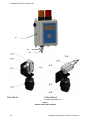
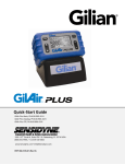
Remote Sensor Kits
Installation Manual
Document No. 360-0127-01
(Revision C)
Sensidyne, LP
1000 112th Circle N, Suite 100
St. Petersburg, Florida 33716 USA
800-451-9444 • +1 727-530-3602 • +1 727-539-0550 [fax]
web: www.sensidyne.com • e-mail: [email protected]
SensAlarm Plus Remote Sensor Kit
WARNINGS PAGE
WARNINGS
READ AND UNDERSTAND ALL WARNINGS BEFORE USE
Read and understand ALL warnings before using this product. Failure to read, understand, and comply
with ALL warnings could result in property damage, severe personal injury, or death.
Installation must be done in accordance with all local electrical codes. Follow standard grounding
procedures when wiring the Remote Sensor Kit. All warnings and installation instructions should be read
and understood as contained in the SensAlarm Plus Universal Gas Monitoring System User Manual
(P/N 360-0126-01).
Sensor Interface Assembly must be mounted such that condensation and dust does not collect on the
Sensor.
Read and understand ALL applicable federal, state, and local environmental health and safety laws and
regulations, including OSHA. Ensure complete compliance with ALL applicable laws and regulations
before and during use of this product.
The user/installer must understand the Hazardous Area Protection Concepts and Area Classifications
applicable to their operation.
UNDER NO CIRCUMSTANCES should this product be used except by qualified, trained, technically
competent personnel and not until the warnings, User Manual, labels, and other literature accompanying
this product have been read and understood.
Failure to read and understand the User Manual may result in preventable severe personal injury or
death.
DO NOT remove, cover, or alter any label or tag on this product, its accessories, or related products.
DO NOT operate this product should it malfunction or require repair. Operation of a malfunctioning
product, or a product requiring repair may result in serious personal injury or death.
DO NOT attempt to repair or modify instrument, except as specified in the Operation & Service Manual. If
repair is needed, contact the Sensidyne Service Dept. to arrange for a Returned Material Authorization
(RMA) (See Section in the SensAlarm Plus Universal Gas User Manual (P/N 360-0126-01) for details).
The SensAlarm Plus Universal Gas Monitoring System is an ambient air monitoring device. Restricting
the access of ambient air to the sensor may result in less than optimal monitoring performance.
Sensidyne Document No. 360-0127-01 (Rev C)
3
SensAlarm Plus Remote Sensor Kit
NOTES:
1. The sensor may be oriented from horizontal down to vertical. The surface of the
sensor must be protected from moisture (condensation) and dust.
4
Sensidyne Document No. 360-0127-01 (Rev C)
SensAlarm Plus Remote Sensor Kit
• 821-0301-01 Remote Sensor Kit
for use with
SenAlarm Plus Models
SensAlarm Plus Remote Sensor Kit (P/N 821-0301-01) contains the following items
(Note: References in brackets refer to letter/number references in Figure 1):
Ref No.............................Sensidyne.P/N
[A-2] ........................550-4003-01
[A-3] ........................522-0002-02
[A-3] ........................522-0002-03
[A-3] ........................522-0002-04
[A-4, A-6].................7017291
(Not shown) ............205-0081-01
[A-7] ........................380-0021-01
DESCRIPTION
Aluminum Condulet Nipple, ¾ NPT (Qty 1)
Cover, Condulet (Qty = 1) (Shown Assembled)
Gasket, Neoprene, (Qty = 1) (Shown Assembled)
Junction Condulet with two 90º ¾ NPT openings
Watertight Cable Entry / Cable Strain Relief (Qty = 2)
Splice 2 pos (Qty = 4)
Bracket Weld Assembly (Black Anodized) (Qty 1)
Cable Specification: 18AWG x 4 Conductor (Shielded) uH/ft < 0.2, pf/ft < 60, Max length 100ft/30m
Cable to be Customer Supplied. Belden 27326AS or equivalent.
Installation
Refer to Figure 1 and install the Remote Sensor Kit as follows:
1)
Fasten the Bracket [A-7] to the desired location. Sensor Interface Assembly must be mounted such
that condensation and dust does not collect on the Sensor. Thread the wires from the Sensor
Interface Assembly [A-8] through the Bracket [A-7] and Nipple [A-2], tighten to secure.
(Note: If you are using tools to tighten the Sensor Interface Assembly make certain you use them
ONLY on the Aluminum hex nut which came attached to the top of the Sensor Interface Assembly.)
2.)
Thread the wires from the Sensor Interface Assembly [A-8] into the lower opening of the Junction
Condulet [A-3]. Tighten the the Junction Condulet [A-3] to the Nipple [A-2]
(Note: If you are using tools to tighten the Sensor Interface Assembly make certain you use them
ONLY on the Aluminum hex nut which came attached to the top of the Sensor Interface Assembly.)
3)
Thread the customer-supplied remote cable [A-5] through the Watertight Strain Relief [A-6].and
tighten to secure remote cable.
4)
Wire the remote cable to the interface using 4 of the Splices provided.
Wire accordingly (R = Red, B = Black, O = Orange, Y = Yellow).
Install the Condulet Gasket and Cover.)
5)
Route and secure the customer-supplied remote cable [A-5] to the SensAlarm Plus Location [A-1].
7)
Thread the wires through the Watertight Strain Relief [A-4], and tighten to secure remote cable.
8)
Wire the remote cable to the SensAlarm [A-1]. Wire accordingly (R = Red, B = Black, O = Orange,
Y = Yellow). Connect the shield wire to the TB2 Pin 5 Barrier PCA in the SensAlarm Plus.
Sensidyne Document No. 360-0127-01 (Rev C)
5
SensAlarm Plus Remote Sensor Kit
A-1
A-4
A-5
Floor Mount
Ceiling Mount
Invert Mounting Bracket A-7
Figure 1
Remote Sensor Kit Installation
6
Sensidyne Document No. 360-0127-01 (Rev C)
Sensidyne, LP
1000 112th Circle N, Suite 100
St. Petersburg, Florida 33716 USA
800-451-9444 • +1 727-530-3602 • +1 727-539-0550 [fax]
web: www.sensidyne.com • e-mail: [email protected]
8
Sensidyne Document No. 360-0127-01 (Rev C)