1
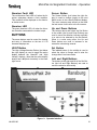
SERVICE MANUAL
LN-9625-00
August — 2014
MicroPak 2e
Single Bell Controller
MODEL:
A13613-XX
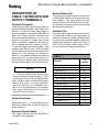
IMPORTANT: Before using this equipment, carefully read
SAFETY PRECAUTIONS, starting on page 1, and all instructions
in this manual. Keep this Service Manual for future reference.
Service Manual Price:
$50.00 (U.S.)
NOTE: This is the first release of this manual.
LN-9625-00
MicroPak 2e Single Bell Controller- Contents
CONTENTS
PAGE
SAFETY:
1-7
SAFETY PRECAUTIONS ......................................................................................................... 1
HAZARDS / SAFEGUARDS................................................................................................... 2-6
INTRODUCTION:
8-11
GENERAL DESCRIPTION ........................................................................................................ 8
SAFETY FEATURES ................................................................................................................ 8
DISPLAYS ................................................................................................................................ 8
SPECIFICATIONS .................................................................................................................... 9
INSTALLATION:
10-17
MICROPAK 2E INPUT POWER.............................................................................................. 10
SAFETY GROUND ................................................................................................................. 10
LOW VOLTAGE CABLES ....................................................................................................... 10
ETHERNET CABLES .............................................................................................................. 10
INTERLOCKS AND OUTPUTS ............................................................................................... 11
CONTROLLER CABINET, REAR VIEWS .......................................................................... 12-13
CONNECTOR P2, ASSEMBLY VIEW ..................................................................................... 14
DESCRIPTION OF TABLE 1 INTERLOCK AND OUTPUT TERMINALS ................................ 15
MICROPAK 2E BELL CONNECTIONS ................................................................................... 16
BELL INTERLOCKING............................................................................................................ 17
MICROPAK 2E GROUNDING THEORY ................................................................................. 18
OPERATION:
20-25
OPERATING CONTROLS ................................................................................................. 20-21
MENU OPERATIONS ........................................................................................................ 22-23
ETHERNET/IP NETWORK SETUP.................................................................................... 23-24
OPERATING PROCEDURES ............................................................................................ 24-25
MAINTENANCE:
26-31
TROUBLESHOOTING
26
TROUBLESHOOTING HIGH VOLTAGE / CABLE CONTINUITY TEST
26
TROUBLESHOOTING SPEED CONTROL ............................................................................. 27
TROUBLESHOOTING GUIDE ........................................................................................... 28-29
TABLE 2. OHMMETER MEASUREMENTS ............................................................................ 30
PARTS:
32-33
SINGLE BELL CONTROLLER PARTS DIAGRAM / PARTS LIST ........................................... 32
WARRANTY POLICIES:
34
LIMITED WARRANTY............................................................................................................. 34
LN-9625-00
MicroPak 2e Single Bell Controller- Contents
LN-9625-00
MicroPak 2e Single Bell Controller - Safety
SAFETY
SAFETY PRECAUTIONS
Before operating, maintaining or servicing any
Ransburg electrostatic coating system, read
and understand all of the technical and safety
literature for your Ransburg products. This
manual contains information that is important
for you to know and understand. This information relates to USER SAFETY and PREVENTING EQUIPMENT PROBLEMS. To help
you recognize this information, we use the following symbols. Please pay particular attention
to these sections.
A WARNING! states information to alert you
to a situation that might cause serious injury if instructions are not followed.
A CAUTION! states information that tells
how to prevent damage to equipment or
how to avoid a situation that might cause
minor injury.
!
The user MUST read and be familiar
with the Safety Section in this manual and
the Ransburg safety literature therein
identified.
This manual MUST be read and thoroughly understood by ALL personnel who
operate, clean or maintain this equipment!
Special care should be taken to ensure that
the WARNINGS and safety requirements
for operating and servicing the equipment
are followed. The user should be aware of
and adhere to ALL local building and fire
codes and ordinances as well as NFPA-33
SAFETY STANDARD, LATEST EDITION,
prior to installing, operating, and/or servicing this equipment.
!
A NOTE is information relevant to the procedure in progress.
While this manual lists standard specifications
and service procedures, some minor
deviations may be found between this literature
and your equipment. Differences in local codes
and plant requirements, material delivery
requirements, etc., make such variations
inevitable. Compare this manual with your
system installation drawings and appropriate
Ransburg equipment manuals to reconcile
such differences.
WARNING
WARNING
The hazards shown on the following
pages may occur during the normal use
of this equipment. Please read the hazard chart beginning on page 2.
Careful study and continued use of this manual
will provide a better understanding of the
equipment and process, resulting in more efficient operation, longer trouble-free service and
faster, easier troubleshooting. If you do not
have the manuals and safety literature for your
Ransburg system, contact your local
Ransburg representative or Ransburg.
LN-9625-00
1
MicroPak 2e Single Bell Controller - Safety
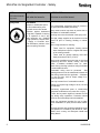
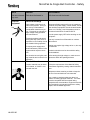
AREA
HAZARD
SAFEGUARDS
Tells where hazards
may occur.
Tells what the hazard is.
Tells how to avoid the hazard.
Spray Area
Fire Hazard
Improper or inadequate operation and maintenance procedures will cause a fire hazard.
Protection against inadvertent
arcing that is capable of causing
fire or explosion is lost if any
safety interlocks are disabled
during operation. Frequent Power Supply or Controller shutdown indicates a problem in the
system requiring correction.
Fire extinguishing equipment must be present in
the spray area and tested periodically.
Spray areas must be kept clean to prevent the accumulation of combustible residues.
Smoking must never be allowed in the spray area.
The high voltage supplied to the atomizer must be
turned off prior to cleaning, flushing or maintenance.
When using solvents for cleaning:
Those used for equipment flushing should
have flash points equal to or higher than those
of the coating material.
Those used for general cleaning must have
flash points above 100°F (37.8°C).
Spray booth ventilation must be kept at the rates
required by NFPA-33, OSHA, country, and local
codes. In addition, ventilation must be maintained during cleaning operations using flammable
or combustible solvents.
Electrostatic arcing must be prevented. Safe
sparking distance must be maintained between the
parts being coated and the applicator. A distance
of 1 inch for every 10KV of output voltage is required at all times.
Test only in areas free of combustible material.
Testing may require high voltage to be on, but only
as instructed.
Non-factory replacement parts or unauthorized
equipment modifications may cause fire or injury.
If used, the key switch bypass is intended for use
only during setup operations. Production should
never be done with safety interlocks disabled.
Never use equipment intended for use in waterborne installations to spray solvent based materials.
The paint process and equipment should be set up
and operated in accordance with NFPA-33, NEC,
OSHA, local, country, and European Health and
Safety Norms.
2
LN-9625-00
MicroPak 2e Single Bell Controller - Safety
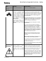
AREA
HAZARD
Tells where hazards Tells what the hazard is.
may occur.
Spray Area
SAFEGUARDS
Tells how to avoid the hazard.
Explosion Hazard
Improper or inadequate opera- Electrostatic arcing must be prevented. Safe
tion and maintenance proce- sparking distance must be maintained between the
dures will cause a fire hazard.
parts being coated and the applicator. A distance
of 1 inch for every 10KV of output voltage is reProtection against inadvertent
quired at all times.
arcing that is capable of causing
fire or explosion is lost if any
Unless specifically approved for use in hazardous
safety interlocks are disabled
locations, all electrical equipment must be located
during operation.
outside Class I or II, Division 1 or 2 hazardous
Frequent Power Supply or Con- areas, in accordance with NFPA-33.
troller shutdown indicates a
problem in the system requiring Test only in areas free of flammable or combuscorrection.
tible materials.
The current overload sensitivity (if equipped)
MUST be set as described in the corresponding
section of the equipment manual. Protection
against inadvertent arcing that is capable of
causing fire or explosion is lost if the current overload sensitivity is not properly set. Frequent
power supply shutdown indicates a problem in the
system which requires correction.
Always turn the control panel power off prior to
flushing, cleaning, or working on spray system
equipment.
Before turning high voltage on, make sure no objects are within the safe sparking distance.
Ensure that the control panel is interlocked with the
ventilation system and conveyor in accordance
with NFPA-33, EN 50176.
Have fire extinguishing equipment readily available
and tested periodically.
General Use and
Maintenance
Improper operation or mainte- Personnel must be given training in accordance
nance may create a hazard.
with the requirements of NFPA-33, EN 60079-0.
Personnel must be properly Instructions and safety precautions must be read
trained in the use of this equip- and understood prior to using this equipment.
ment.
Comply with appropriate local, state, and national
codes governing ventilation, fire protection, operation maintenance, and housekeeping. Reference
OSHA, NFPA-33, EN Norms and your insurance
company requirements.
LN-9625-00
3
MicroPak 2e Single Bell Controller - Safety
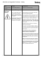
AREA
HAZARD
SAFEGUARDS
Tells where hazards
may occur.
Tells what the hazard is.
Tells how to avoid the hazard.
Spray Area /
High Voltage
Equipment
Electrical Discharge
There is a high voltage device
that can induce an electrical
charge on ungrounded objects
which is capable of igniting coating materials.
Parts being sprayed and operators in the spray
area must be properly grounded.
Parts being sprayed must be supported on conveyors or hangers that are properly grounded. The
resistance between the part and earth ground must
Inadequate grounding will cause not exceed 1 meg ohm. (Refer to NFPA-33.)
a spark hazard. A spark can
Operators must be grounded. Rubber soled insuignite many coating materials
lating shoes should not be worn. Grounding straps
and cause a fire or explosion.
on wrists or legs may be used to assure adequate
ground contact.
Operators must not be wearing or carrying any
ungrounded metal objects.
When using an electrostatic handgun, operators
must assure contact with the handle of the applicator via conductive gloves or gloves with the palm
section cut out.
NOTE: REFER TO NFPA-33 OR SPECIFIC
COUNTRY SAFETY CODES REGARDING
PROPER OPERATOR GROUNDING.
All electrically conductive objects in the spray area,
with the exception of those objects required by the
process to be at high voltage, must be grounded.
Grounded conductive flooring must be provided in
the spray area.
Always turn off the power supply prior to flushing,
cleaning, or working on spray system equipment.
Unless specifically approved for use in hazardous
locations, all electrical equipment must be located
outside Class I or II, Division 1 or 2 hazardous
areas, in accordance with NFPA-33.
4
LN-9625-00
MicroPak 2e Single Bell Controller - Safety
AREA
HAZARD
SAFEGUARDS
Tells where hazards
may occur.
Tells what the hazard is.
Tells how to avoid the hazard.
Electrical
Equipment
Electrical Discharge
High voltage equipment is utilized in the process. Arcing in
the vicinity of flammable or
combustible materials may occur. Personnel are exposed to
high voltage during operation
and maintenance.
Unless specifically approved for use in hazardous
locations, the power supply, control cabinet, and all
other electrical equipment must be located outside
Class I or II, Division 1 and 2 hazardous areas in
accordance with NFPA-33 and EN 50176.
Turn the power supply OFF before working on the
equipment.
Protection against inadvertent
arcing that may cause a fire or
Test only in areas free of flammable or combusexplosion is lost if safety circuits tible material.
are disabled during operation.
Testing may require high voltage to be on, but only
Frequent power supply shutas instructed.
down indicates a problem in the
system which requires correcProduction should never be done with the safety
tion.
circuits disabled.
An electrical arc can ignite coat- Before turning the high voltage on, make sure no
ing materials and cause a fire or objects are within the sparking distance.
explosion.
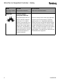
Toxic Substances
Chemical Hazard
Certain materials may be harmful if inhaled, or if there is contact with the skin.
Follow the requirements of the Material Safety
Data Sheet supplied by coating material manufacturer.
Adequate exhaust must be provided to keep the
air free of accumulations of toxic materials.
Use a mask or respirator whenever there is a
chance of inhaling sprayed materials. The mask
must be compatible with the material being
sprayed and its concentration. Equipment must be
as prescribed by an industrial hygienist or safety
expert, and be NIOSH approved.
LN-9625-00
5
MicroPak 2e Single Bell Controller - Safety
AREA
HAZARD
SAFEGUARDS
Tells where hazards
may occur.
Tells what the hazard is.
Tells how to avoid the hazard.
Spray Area
Explosion Hazard—
Incompatible Materials
Halogenated hydrocarbon solvents for example: methylene
chloride and 1,1,1,Trichloroethane are not chemically compatible with the aluminum that
might be used in many system
components. The chemical reaction caused by these solvents
reacting with aluminum can become violent and lead to an
equipment explosion.
6
Aluminum is widely used in other spray application
equipment such as material pumps, regulators,
triggering valves, etc. Halogenated hydrocarbon
solvents must never be used with aluminum equipment during spraying, flushing, or cleaning. Read
the label or data sheet for the material you intend
to spray. If in doubt as to whether or not a coating
or cleaning material is compatible, contact your
coating supplier. Any other type of solvent may be
used with aluminum equipment.
LN-9625-00
MicroPak 2e Single Bell Controller - Safety
NOTES
LN-9625-00
7
MicroPak 2e Single Bell Controller - Introduction
INTRODUCTION
GENERAL DESCRIPTION
The Ransburg MicroPak 2e Single Bell
Controller (A13613-XX), is a free standing
unit which provides voltage to a remotely
located cascade and closed loop speed
control for Ransburg atomizer units.
The Ransburg MicroPak 2e High Voltage
Controller uses a combination of proven high
voltage generation technology including
microprocessor-based control with diagnostic
and communication functions.
A variable
voltage output is used to supply a cascade
that amplifies the voltage to a high value. It
also uses both current and voltage feedback
information to maintain the desired set point.
The processor circuitry provides the maximum
in applicator transfer efficiency, while
maintaining the maximum safety
The Ransburg MicroPak 2e Atomizer
Controller builds upon previous Ransburg
control technology and tightly integrates the
MicroPak 2e Atomizer Controller with the
MicroPak 2e High Voltage Controller.
SAFETY FEATURES
When used with the appropriate applicators
and cascades, the Ransburg MicroPak 2e
Single Bell Controller provides the ultimate in
operational safety.
The high voltage
protections include Overvoltage, Overcurrent,
Di/Dt, Dv/Dt and Interlock Open. In addition,
the microprocessor circuits allow the use of
output load curve control, which limits the high
voltage output to safe levels when the controls
are set responsibly and safe distances are
observed and followed.
The protections
provided by the atomizer control include
Overspeed, Underspeed, Loss of Bearing Air,
Loss of Feedback and Interlock Open. These
safety checks assure that the Atomizer is run
within its safe operational limits. And finally,
8
since the high voltage and atomizer
controllers are tightly integrated, the
operational status of each unit can be
communicated to the other unit.
This
provides added benefits such as forcing a
brake assisted stop of the Atomizer when an
interlock opens.
DISPLAYS
The front panel contains two LCD displays
each containing four lines of 20 characters.
These allow real-time monitoring of cascade
voltage and current as well as bell speed
and bearing air pressure. All readings are
true values derived from feedback signals
originating in the cascade and atomizer
units.
In addition to providing a continuous display
of operating parameters, the front panel
display also provides a means to display
and change user adjustable operating
parameters such as Overcurrent, Overvoltage, Di/Dt and Dv/Dt.
The Ransburg MicroPak 2e Single Bell
Controller (A13613-XX), is available as
follows:
Part #
Description
A13613-00
Bell Control, HP404/RP404
A13613-01
Bell Control, RP1000
A13613-02
AutoGun, HP404/HP505
LN-9625-00
MicroPak 2e Single Bell Controller - Introduction
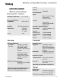
SPECIFICATIONS
(At Sea-Level Conditions)
Environmental / Physical
Operating Temperature:
0°C to +55°C
Storage and Shipping
Temperature:
-40°C to +85°C
Humidity:
Cabinet Size:
Weight:
95% Non-Condensing
13.0" Wide
18.0” Deep
7.0” Height
23 lbs.
EtherNet/IP
Discrete Signals:
Inputs:
Misc IO Interlock/Trigger
Door Interlock
Booth Air Interlock
Outputs:
Interlock Out
External Power Enable
System Alarm
Controller Operating Range
High Voltage:
0-100kV, settable in 1kV
increments
Current:
HP404/RP404
A12760/A12761
HP505
RP1000
0-125 microamps
0-150 microamps
0-240 microamps
0-1000 microamps
Pneumatic
Electrical
DC Power Required: *
Controller :
24V DC @ 0.5 Amps
Cascade:
Controls
Network:
24V DC @ 6.0 Amps
(fully loaded output),
RansPak 1000 (RP1000)
Cascade
24V DC @ 2.0 Amps
(fully loaded output),
HP404, RP404, HP505,
A12760 and A12761
Cascades
AC Electrical Requirements:
90-264 VAC @ 1.5 Amps
47/63 Hertz
* DC power supplied from 24VDC built-in, regulated power supply which has overcurrent
(40%) and overvoltage (20%) protection.
Pneumatic Inputs
Supply Air:
0-100 psi (0-6.9 bar)
filtered to 40 microns
80 psi (5.5 bar) minimum
required for specified performance
Bearing Air:
Feedback of actual rotator bearing air pressure
Pneumatic Outputs
Turbine Pilot Air: Zero to input pressure
(variable)
Brake Air:
Zero to input pressure
(On or Off)
These I/Os are not present on A13613-02
Optical
Optical Input
Bell Speed:
Feedback of actual bell
speed up to 99K RPM
This input is not present on A13613-02
LN-9625-00
9
MicroPak 2e Single Bell Controller - Installation
INSTALLATION
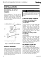
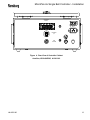
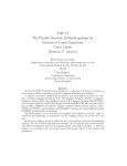
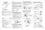
MICROPAK 2E INPUT
POWER
Plug the detachable AC line cord into the
receptacle on the rear of the MicroPak 2e
Single Bell Controller Cabinet. Plug the other
end into a properly grounded 110/230 Volt
AC, 50/60 Hz. outlet. See Figure 1 below for
location on the cabinet.
!
CAUTION
The ground wire assembly MUST be connected from the MicroPak 2e Single Bell Controller Cabinet ground stud to a true earth
ground.
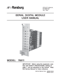
LOW VOLTAGE CABLES
Standard Low Voltage Cable
For HP404/RP404/HP505
(A11353-XX)
Plug the connector of the low voltage cable
assembly into the “LOW VOLTAGE”
receptacle on the rear of the controller (see
Figure 2). When making the connection, line
the red dot on the connector with the red mark
on the receptacle and push in until it clicks. To
remove, simply pull back on the knurled
portion of the connector.
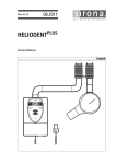
Standard Low Voltage Cable
For RP1000
(A13745-XX)
Figure 1: Partial Rear View of Cabinet
SAFETY GROUND
Install the ground wire assembly supplied with
the MicroPak 2e Single Bell Controller Cabinet
from the ground stud on the rear of the cabinet
to a true earth ground. For maximum noise
immunity, cut the ground wire assembly to the
shortest length required and reinstall the end
lug before making connections.
10
Plug the connector of the low voltage cable
assembly into the “LOW VOLTAGE”
receptacle on the rear of the controller (see
Figure 3). When making the connection, align
the inner portion of the connector before
screwing the connector firmly into place. To
remove, reverse the operation.
ETHERNET CABLES
CAT 5 CABLE WITH RJ45
If the user plans to utilize the MicroPak 2e
Single Bell Controller’s EtherNet/IP interface
for remote control, they must provide a
network connection for the Controller. This is
done by plugging a standard CAT 5 cable into
the RJ45 socket labeled “ETHERNET I/P” on
the rear of the controller (see Figure 2).
LN-9625-00
MicroPak 2e Single Bell Controller - Installation
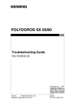
INTERLOCKS AND
OUTPUTS
Interlock and output connections are made to
connector P2 on the rear of the controller. P2
consists of three, 8 position terminal blocks A,
B, and C (see Figure 5). To wire these
terminal blocks, perform the following (see
Figure 5):
1. Loosen the 2 screws of P2’s connector
housing and remove P2 from the controller.
2. Loosen the 4 screws holding the terminal
block assembly to the inside of the connector housing and remove the terminal
block assembly from the housing.
3. Feed the Output / Interlock cable(s)
through the cable grommet attached to the
connector housing and pull out the other
side. It may be necessary to remove the
cable grommet to fit the cable(s) through.
If so, slide the grommet connections onto
the cable(s) in the order shown in Figure 5
before pulling the cable through the connector housing.
NOTE
NOTE
If multiple Output / Interlock cables are
used, connect the exposed 1.5” cable
braids together using copper tape.
6. Rotate the connector housing to achieve
desired routing of the cable bundle (right
or left), then reinstall the terminal block
assembly into the connector housing.
7. Tighten the connector grommet ensuring
the grommet spring makes 360° contact
with the exposed cable braid/copper tape
for maximum noise immunity.
For maximum noise immunity, the shields of
the output and interlock cables should also be
connected to earth ground at the end opposite
to the MicroPak 2e Single Bell Controller
connections.
If it is necessary or desired to run the interlock
and Output cable(s) through conduit, an
adapter can be readily purchased that
converts the PG21 male threads of the P2
connector housing to 3/4” NPT male threads.
This adapter is available through McMasterCarr as their Part Number 7842K7.
For maximum noise immunity, all wiring
should be run in cables having a foil shield
with an overall braided shield. The foil shield
provides 100% shielding, while the braid
provides a means of making proper 360°
shield terminations at the cable ends.
4. Strip the jacket off the cable(s) 3” from the
end and remove the braid 1.5” from the
end (see Figure 6).
5. Strip the individual cable wires, install appropriate wire ferrules, and connect to the
terminal blocks according to Table 1.
LN-9625-00
11
MicroPak 2e Single Bell Controller - Installation
INTERLOCK
INPUTS
AIR IN
EXHAUST
OUT
100 - 240 VAC
50 - 60 Hz
FIBER
OPTIC
ETHERNET
I/P
TURBINE
PILOT
LOW
VOLTAGE
BRAKE
PILOT
BEARING
AIR
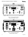
Figure 2: Rear View of Controller Cabinet
Bell Control, HP404/RP404, A13613-00
INTERLOCK
INPUTS
AIR IN
EXHAUST
OUT
100 - 240 VAC
50 - 60 Hz
FIBER
OPTIC
ETHERNET
I/P
TURBINE
PILOT
RP-1000
LOW
VOLTAGE
BRAKE
PILOT
BEARING
AIR
Figure 3: Rear View of Controller Cabinet
Bell Control, RP1000, A13613-01
12
LN-9625-00
MicroPak 2e Single Bell Controller - Installation
INTERLOCK
INPUTS
100 - 240 VAC
50 - 60 Hz
ETHERNET
I/P
LOW
VOLTAGE
Figure 4: Rear View of Controller Cabinet
AutoGun, HP404/HP505, A13613-02
LN-9625-00
13
MicroPak 2e Single Bell Controller - Installation
Figure 5: Assembly of Connector P2
Figure 6: Stripping of I/O Cables
14
LN-9625-00
MicroPak 2e Single Bell Controller - Installation
DESCRIPTION OF
TABLE 1 INTERLOCK AND
OUTPUT TERMINALS
Interlock Terminals
These terminals allow interlocking of high voltage and atomizer operation with safety components. In order to obtain high voltage or
atomizer operation, the enabled MicroPak 2e
Single Bell Control interlock terminals must
have a connection between the (+) and (-) terminals by a jumper or voltage free contact.
When an interlock is enabled, if the high voltage is activated without the interlock (+) and () terminals being connected together, high
voltage output will not occur. These terminals
are provided to interlock the controller with the
exhaust fan and conveyor as required by
NFPA-33. If an enabled interlock connection is
momentarily lost, the connection must be restored and the controller fault cleared before
the high voltage output can be turned back on.
NOTE
The fourth interlock input Remote Stop
cannot be disabled through software. If the
user does not wish to use the Remote Stop
input, a jumper must be installed to close the
Remote Stop circuit. It can be placed between A4 and A8 of P2, or between J5-13
and J5-14 of the MicroPak 2e HV Controller
(See current “MicroPak 2e HV & Atomizer
Controller” service manual.).
Output Terminals
Each output pair (+,-) is connected to an isolated relay contact which is rated 30 VDC @ 2
amps, maximum.
System Alarm Out
This relay output signal indicates the MicroPak
2e Single Bell Controller is shutdown due to a
fault condition. This signal reflects the fault
status of both the HV controller and the Atomizer controller, such that if either unit is faulted
the alarm will be activated.
Interlock Out
This relay output signal indicates the MicroPak
2e Single Bell Controller has determined all
enabled interlocks are closed, cascade power
is present and cascade feedback signals are
operating as expected. When this output is
active and the System Alarm output is inactive, the controller is ready to be activated.
TABLE 1
Interlocks:
P2
Terminal
Door (+)
Door (-)
Booth Air (+)
Booth Air (-)
Misc Interlock / Trigger (+)
Misc Interlock / Trigger (-)
Remote Stop (+)
Remote Stop (-)
A1
A5
A2
A6
A3
A7
A4
A8
Outputs:
External Power Enable (+)
External Power Enable (-)
System Alarm Out (+)
System Alarm Out (-)
Interlock Out (+)
Interlock Out (-)
C3
C7
C2
C6
C1
C5
External Power Enable
This signal indicates that the MicroPak 2e
has power and is operating.
LN-9625-00
15
MicroPak 2e Single Bell Controller - Installation
NOTE
The following sections which describe
Bell Connections and Operations do not apply to AutoGun controllers (i.e. A13613-02)
MICROPAK 2e
BELL CONNECTIONS
PNEUMATICS
Air Supply
The air needed to control a Ransburg Atomizer unit is provided through the AIR IN connector shown in Figures 2 and 3. This is a standard push to connect air fitting which accepts
5/16“ (8 mm) OD pneumatic tubing.
Exhaust Out
This fitting is used to discharge any waste air
from the speed control regulator and brake
valve. It is a standard push to connect air fitting which accepts 5/16“ (8 mm) OD pneumatic tubing. The location of the Exhaust Out
connector is shown in Figures 2 and 3.
Turbine Pilot
Bearing Air
This input is used to monitor the pressure of
the bearing air being supplied to the atomizer.
It connects directly to a 0-100 psi P-to-E sensor which the MP2e controller continuously
monitors. The low pressure fault setting defaults to 80 psi for all Ransburg atomizers.
The connection is a standard push to connect
air fitting which accepts 5/32“ (4mm) OD pneumatic tubing. The location of the Bearing Air
connector is shown in Figures 2 and 3.
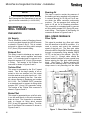
BELL SPEED FEEDBACK
Fiber Optic
This signal is provided via a fiber optic cable
from the atomizer to the MP2e controller. It is
used to monitor and control the rotational
speed of the bell unit. The fiber optic cable
enters the MP2e Single Bell Controller cabinet
through a compression fitting labeled FIBER
OPTIC, on the rear of the cabinet. (See Figures 2 and 3.) Enough cable should be
placed inside the cabinet to have a gentle loop
before entering the fiber optic cable retaining
block. (See Figure 7) Before inserting the
cable into the retaining block, verify the nylon
clamp screw is not protruding into the cable
This output is generated by the E to P speed
control. Due to the large quantity of air required to drive an atomizer unit, this output
must be used as an air pilot signal to a 1:1 volume booster provided by the user. One suitable volume booster is Ransburg part number
A11111-00. The TURBINE PILOT connection
is a standard push to connect air fitting which
accepts 5/32“ (4 mm) OD pneumatic tubing.
The location of the Turbine Pilot connector is
shown in Figures 2 and 3.
Brake Pilot
This output is generated by an on/off air valve.
It can be used directly to drive the atomizer’s
brake air input. The connection is a standard
push to connect air fitting which accepts
5/32“ (4 mm) OD pneumatic tubing. The location of the Brake Pilot connector is shown in
Figures 2 and 3.
16
Figure 7: Fiber Cable Position
LN-9625-00
MicroPak 2e Single Bell Controller - Installation
hole. Once the hole is clear insert the fiber
cable into the hole until it is fully seated. Then
tighten the nylon screw to hold the cable in
place and tighten the compression fitting to
retain the looped cable.
BELL INTERLOCKING
The following system interlocks are required to
prevent equipment damage.
Bearing air should remain on at all times
and only shut-off by turning off the main air
to the pneumatic control cabinet.
Turbine air must be removed if bearing air
falls below 80 psi (551.6 kPa) at the atomizer. To facilitate this, Ransburg atomizers
provide two interconnected bearing air
ports, one for supply air and the other to
be used as a return signal for measuring
bearing air pressure at the atomizer. If
bearing air falls below 80 psi (551.6 kPa)
at the atomizer, the turbine air should be
automatically interlocked to shut off. This
interlock is provided by the MicroPak
2e Atomizer Controller. (See current MicroPak 2e HV & Atomizer Controller service manual.)
Turbine air and brake air must be interlocked to prevent both from being used
simultaneously. This interlock is provided by the MicroPak 2e Atomizer Controller. (See current MicroPak 2e HV &
Atomizer Controller service manual.)
It should not be possible for the coating
material to be sprayed unless the turbine is
spinning. It is the user’s responsibility
to implement this interlock.
!
CAUTION
When the turbine air is turned off, the
turbine will continue to operate or “coast
down” for about two minutes. Provisions
should be made to assure that the operator
waits at least three minutes, after shutting
off the turbine air and before shutting off the
main air supply.
The bell cup must be removed when
making flow checks. If the paint is turned
on when the bell cup is mounted and the
turbine shaft is not rotating, paint will enter
the shaft and possibly damage the air bearing. Material flow checks (flow rate verification) must be made with the bell cup off and
the turbine not rotating. This is a special
maintenance condition and not for normal
operation. Normally pneumatic interlocks
will not allow the paint to trigger on when
the turbine air is off.
!
WARNING
The high voltage and/or coating material must never be turned on unless the
bell cup is mounted on the motor shaft
and the turbine is rotating.
Pneumatic input to the turbine air inlet
must be controlled to prevent the turbine
from exceeding the maximum rated speed
of the configured atomizer. (See
“Specifications” in the “Introduction” section.) This behavior is provided by the
MicroPak 2e Atomizer Controller (See
current MicroPak 2e HV & Atomizer Controller service manual).
High voltage must be interlocked with the
solvent valve pilot signal to prevent solvent
flow while high voltage is energized (direct
charge only). It is the user’s responsibility to implement this interlock.
High voltage must never be turned on
while cleaning solvent is being sprayed either through the applicator supply or the
cup wash line. High voltage and both solvent triggers must be interlocked (direct
charge only).
Any other interlocks required by local, national code or international code.
Never spray solvent with
high voltage on.
LN-9625-00
17
MicroPak 2e Single Bell Controller - Installation
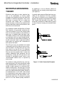
MICROPAK GROUNDING
THEORY
Electrical noise refers to stray electrical signals in the atmosphere at various signal
strengths and frequencies that can affect the
operation of electrical equipment. One of the
best ways to prevent this is to shield the
equipment and cables with a continuous
ground envelope, such that any incident noise
will be conducted to earth ground before it can
affect the circuit conductors.
as pigtailing) is not an effective method of
shielding and can actually make things worse
(see Figure 6).
A special cable grommet fitting has been provided for I/O connector P2 of the controller
(see Figure 3). When the nut is tightened, the
spring in the grommet compresses and makes
360° contact with the braid of the cable. This
electrically connects the cable braid to ground
via the connector housing and controller back
panel.
For conductors inside the MicroPak 2e Single
Bell Controller, the grounded enclosure provides this envelope. For the low voltage cable
that run from the controller to the atomizer or
spray gun, a shielded cable has been used.
The shield consists of an overall foiled shield
in combination with an overall braided shield.
This provides the most effective shielding, as
the foil covers the “holes” in the braid, and the
braid allows for practical 360° termination at
both ends of the cable.
The AC input cord is not shielded, but instead
is directed to an AC line filter as soon as it enters the cabinet. This filter filters out any noise
that comes in on the AC line. For maximum
noise immunity the AC line is connected to the
filter as soon as possible after it enters the
cabinet. Additional noise protection can be
provided by running the AC input line to the
controller in grounded conduit, which is the
recommended method and is required by
some codes.
For maximum noise protection any user supplied input/output (I/O) wiring should be made
using shielded cable or conduit which is connected to earth ground in a continuous 360°
fashion at both ends. The best way to do this
is to use a conductive connector/fitting at each
end of the cable/conduit that makes contact to
the shield/conduit in a full 360° circle around
the shield/conduit and makes contact to the
grounded enclosure in the same fashion. Connecting the drain wire of a shield to a ground
point on or in the cabinet (usually referred to
18
Figure 8: Cable Connection Examples
LN-9625-00
MicroPak 2e Single Bell Controller - Installation
NOTE REGARDING DIP SWITCHES
Unlike previous MicroPak controllers, the new
MicroPak 2e does not use dipswitches to control hardware configuration. Configuring the
system is now done entirely through configuration menus which are accessible through the
front panel display and interface.
However, there is one set of “factory-only”
dipswitches on each of the MicroPak 2e
boards. These switches are used to set the
internal board address and to configure a
watchdog timer which aids in detecting software malfunctions. Therefore they are not to
be changed by the user as they are reserved
for factory use only.
NOTES
LN-9625-00
19
MicroPak 2e Single Bell Controller - Operation
OPERATION
OPERATING CONTROLS
HV On / Off Switch
AC Power ON/OFF Switch
(Figure 1)
This is a return-to-center momentary toggle
switch. It is only active when the Local/
Remote mode switch is set to Local. It is used
to enable or disable the High Voltage output
and also to clear system faults. When the
System Checks and Current Status are OK,
flipping the switch to the up position (HV On)
will enable the high voltage output. Flipping it
to the down position (HV Off) will disable the
High Voltage Output. If there is a system
fault, flipping this switch to the down position
(also known as the Reset position) will reset
(clear) any faults currently detected by the
system.
Turns AC Power to the MicroPak 2e Single
Bell Controller On or Off.
NOTE
This switch is located on the rear of
the controller.
(Remaining Controls—Figure 9)
MicroPak 2e ON/OFF Switch
The rocker switch at the left edge of the Front
Panel is for power On/Off selection. The
switch controls the application of 24V DC to
the MicroPak 2e HV Controller.
Local / Remote Switch
This is a two position toggle switch used to
determine if the Local (Front Panel) controls
are active or if the Remote EtherNet/IP controls are active. If the switch is up (Local
Mode) the Front Panel controls can change
parameters, enable or disable the high voltage, and clear faults. The Remote EtherNet/
IP connection can look at parameters and values, but cannot change them or enable/
disable the high voltage output. If the switch
is down (Remote Mode) the opposite is true
except that the Front Panel switch may be
changed to local Mode at any time to disable
the Remote Controls and to enable the Local
Controls. Note that if the switch is set to Remote when power is applied, the unit will automatically switch to RUN mode after 3 seconds.
20
Atomizer On / Off Switch
This is a two position toggle switch. When in
LOCAL mode, it enables or disables an attached atomizer (i.e. run or stop). When the
controller is in REMOTE mode this switch is
ignored.
LED'S
Power LED
The Green Power LED is located directly
above the ON/OFF rocker switch, It is on
whenever controller 24 VDC power is On.
HV Fault LED
The red HV Fault LED is lit when the system
detects a fault condition When operating in
"Local Mode", it is cleared by flipping the HV
On/Off switch to the OFF (Reset) position. If
the system is still in a fault condition, it will immediately be lit as the system detects the
fault.
High Voltage LED
The green High Voltage LED displays the current state of the High Voltage Output. This
LED is illuminated whenever High Voltage is
being supplied.
LN-9625-00
MicroPak 2e Single Bell Controller - Operation
Atomizer Fault LED
Screen Button
The red Atomizer Fault LED is lit when the Atomizer subsystem detects a fault condition.
This condition will be displayed on the Atomizer status screen.
The Screen Button (just below the right display) is used to change (toggle) to the next
Menu screen in the currently selected display.
The menu screens wrap around so that after
the last screen it will return to the first screen.
Atomizer LED
The green Atomizer LED is lit when the Atomizer controller commands the turbine to spin.
Up and Down Buttons
The seven buttons used to control the viewing
and entry of information on the two 4 X 20
character displays are:
The buttons above and below the Set Button
in the middle (the Up and Down Buttons) are
used to move the selection indicator vertically
to a value to be selected by the Set Button.
When in a value entry menu, the Up and
Down buttons are used to increase or decrease the value being entered.
HV/AT Button
Set Button
The High Voltage/Atomizer Button (just below
the right display) is used to toggle the active
display between the “Atomizer” and “High
Voltage” displays. Note that the active display
always has a (block character) in the lower
right corner.
This labeled button (in the middle) is used to
select the value to change and to enter the
change after it has been made.
BUTTONS
Left and Right Buttons
The buttons to the right and left of the Set Button (the Left and Right Buttons) are used to
move the selection horizontally.
Figure 9: Operator Interface
LN-9625-00
21
MicroPak 2e Single Bell Controller - Operation
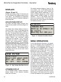
DISPLAYS
(Figure 10 and 11)
As seen previously in Figure 9, there are two
4 X 20 character LCD displays located on the
Front Panel. All modification of parameters
and real-time display of feedback readings is
done using them.
HIGH VOLTAGE DISPLAY
The HIGH VOLTAGE display contains information directly related to the high voltage controller.
The default High Voltage display is shown in
Figure 10 below. Line 1 of the display shows
the current high voltage setpoint (KVSet) in
kilo volts. The arrows which enclose the value
(000) indicate that it may be changed. Line 2
of the display shows the current high voltage
reading (KVAct) and microAmp reading
(uAAct) from the cascade. Line 3 of the display shows the status of cascade feedback
(CHecK) and communications (COMmunications) as both being OK. Line 4 of the display shows that high voltage (HV) is Off and
controller STatuS (Sts) is STPD (Stopped, i.e.
not active). Note at the end of line 4, there is
a (block character). This indicates the active display, that is the one the menu control
buttons will act on.
HIGH VOLTAGE
KVSet000
KVAct 000 uAAct 0000
Chk: OK
Com: OK
HV: Off
Sts: STPD
Figure 10: High Voltage Run Menu Screen
ATOMIZER DISPLAY
The ATOMIZER display contains information
directly related to the atomizer controller
when one is included.
22
The default Atomizer display is shown in Figure 11 below. Line 1 of the display shows the
configured atomizer type. Line 2 shows the
turbine speed setpoint (KRPM-Sp) in thousands of RPMs, followed by current turbine
speed reading (RPMAct) based on turbine
feedback. Line 3 of the display shows that
there are no atomizer faults. Line 4 of the display shows the current reading of the Bearing
Air feedback pressure, in psi.
ATOMIZER
RMA300-500
KRPM-Sp 00 RPMAct 00
No Faults
Bearing Air 000 psi
Figure 11: Atomizer Run Menu Screen
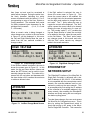
MENU OPERATIONS
On all of the MicroPak 2e menus, if a parameter can be changed it will be proceeded by a
blinking ““ and followed by a blinking “” to
show that it is a changeable value. If there is
more than one changeable value on a screen,
pressing the Up or Down and Left or Right
Buttons will move the selection " "s to the
next value. If there are no changeable values
on a screen then the “Active Screen Indicator”
in the lower right corner will blink. When the
selection " "s surround the value you wish
to change, press the Set Button. If the value
to be changed requires a password, either the
User, System or Config Password Menu will
be displayed allowing you to enter the required
password. After entering the Password, you
are returned to the originally selected value. If
the password was entered correctly, the value
may now be changed. If the entry was incorrect, the password screen will again be displayed. Once a password has been successfully entered, it will remain active for a period
of time that depends on the password type. It
LN-9625-00
MicroPak 2e Single Bell Controller - Operation
then times out and must be re-entered to
make further changes. During the active time,
the block character indicating the active
screen will alternate with the letters U, S or C
corresponding to entry of the User, System or
Config password. The activated time period
for these password types decreases as the
privilege level increases
(U = 4, S = 3 and
C = 2 minutes).
When a numeric value is being changed, a
value change menu, similar to the one shown
in Figure 12, will be displayed. In this menu
the Left and Right Buttons allow the user to
select from the two methods available to
change a value.
HIGH VOLTAGE
Value=0000
Range 0000 to 9999
Inc/DecDigitQuit
Figure 12: Value Change Screen
If the Inc/Dec method is selected, the user is
shown the screen seen in Figure 13. In this
mode, the Up and Down buttons (above and
below the SET Button) can be used to incrementally change the value. The value will increase with the up button and decrease with
the down button until it reaches the maximum
or minimum allowed value.
ATOMIZER
Value000
Range 000 to 100
Inc/Dec Mode
Figure 13: Inc/Dec Change Mode Screen
LN-9625-00
If the Digit method is selected, the user is
shown the screen seen in Figure 14. This
shows the current value to be modified, the
low and high limits for the selected parameter
and the digit mode options to change the current value. The "-" option allows the user to
negate the current value displayed. The “Null”
option causes the current value to be cleared
allowing the user to begin entry of a new value. The ‘number’ option ("0") enables the
Up and Down Buttons to select the next digit
to be added to the value when the user presses the Set Button. The “Save” option saves
any changes made in this screen and exits.
And the “Quit” option cancels any changed
made in the screen and exits.
ATOMIZER
Value=0000
Range 000 to 100
- Null0Save Quit
Digit Mode
Figure 14: Digit Mode Change Screen
ETHERNET/IP
NETWORK SETUP
The EtherNet/IP interface of the MicroPak 2e
Single Bell Controller is delivered with a default IP address of 192.168.0.3. If this address
is not compatible with the users private control
network, the controller address must be customized to reside on the users network. This
is accomplished by first setting the IP address
of the controller to an available address in the
users network, then enabling the EtherNet/IP
interface and finally saving the new configuration before cycling power.
To make these changes, the user must access
the MicroPak 2e Configuration menus. This is
done by setting the Remote/Local switch to
Local and turning on AC power to the MicroPak 2e Single Bell Controller. This causes the
23
MicroPak 2e Single Bell Controller - Operation
controller to boot-up and pause, waiting for
the user to select either Run, Configuration or
Diagnostics on the ATOMIZER display. Use
the Up and Down Arrow pushbuttons to move
the selection arrows to enclose
Configuration and then pressing the SET
pushbutton to enter Configuration Mode. Input focus then shifts to the HIGH VOLTAGE
display where the user can use the Up and
Down arrow and the SET pushbuttons to
modify the IP address, enable the EtherNet/IP
interface and save the new configuration.
5. Turn the AC Power ON/OFF switch (see
Figure 1) to the ON position.
Refer to the “MicroPak 2e HV & Atomizer
Controller” manual, Ransburg number LN9624-00 for further details.
8. Ensure the over-current setpoint (Max uA
Limit) is set above the maximum expected
current, or an overload fault will occur.
The over-current setpoint can be adjusted
using the front panel operator interface
described in the previous section titled
MENU OPERATIONS.
OPERATING
PROCEDURES
(See Figure 1 and 9 for Operating
Controls)
Typical Local Mode
1. Ensure the AC power, safety ground, low
voltage cable, and interlock connections
are made. Ensure the pneumatic connections for supply air, turbine pilot, bearing air
feedback and brake air (if used) are made.
Also ensure that the fiber optic cable which
provides bell speed feedback is installed.
Refer to the “Installation” section of this
manual for descriptions of the above connections.
2. Enable the main turbine air supply. Failure
to do this will cause the Atomizer controller
to detect a Bearing Air Fault, which will
prevent all operation.
3. Set the Local/Remote switch to LOCAL.
4. Set the Atomizer On/Off switch to OFF.
24
6. Turn the MicroPak 2e ON/OFF switch to
the ON position. The HIGH VOLTAGE
and ATOMIZER displays will become active along with the green MicroPak 2e
Power Indicator located above the switch.
7. Press the Set Button to place the controller
into RUN mode. The two display screens
will now look like figures 10 and 11.
9. Move the Atomizer On/Off Switch to the
ON position. The green Atomizer On Indicator should be lit.
10. Adjust
the
bell
speed
setpoint
(TurbnSpdSet) to the desired value.
11. Momentarily push the High Voltage On/Off
Switch to the ON position. The green High
Voltage On Indicator should turn on.
12. Using the front panel operator interface ,
adjust the KV Setpoint (KVSet) to the desired value.
13. To turn high voltage off, momentarily move
the High Voltage On/Off Switch to the OFF
position.
14. To turn the atomizer off, move the Atomizer On/Off Switch to the OFF position.
15. When finished spraying, turn the AC Power ON/OFF Switch (see Figure 1) to the
OFF position to prolong the life of the internal fan.
LN-9625-00
MicroPak 2e Single Bell Controller - Operation
Typical Remote Mode
1. Ensure the AC power, safety ground, low
voltage cable, interlock and Ethernet connections are made. Ensure the pneumatic
connections for supply air, turbine pilot,
bearing air feedback and brake pilot (if
used) are made. Also ensure that the fiber
optic cable which provides bell speed feedback is installed. Refer to the “Installation”
section of this manual for descriptions of
the above connections.
2. Enable the main turbine air supply. Failure
to do this will cause the Atomizer controller
to detect a Bearing Air Fault, which will
prevent operation.
8. From the remote controller, set an appropriate value for Max uA Limit based on the
expected load and the cascade being
used.
9. From the remote controller, set the desired
bell speed and enable the atomizer.
10. From the remote controller, set the desired
KV setpoint and enable high voltage.
11. Disable the high voltage from the remote
controller.
12. Disable the Atomizer from the remote controller.
13. When finished spraying, turn the AC Pow-
3. Set the Local/Remote switch to REMOTE.
4. Set the Atomizer On/Off switch to OFF.
er ON/OFF Switch (see Figure 1) to the
OFF position to prolong the life of the internal fan.
5. Turn the AC Power ON/OFF switch (see
Figure 1) to the ON position.
6. Turn the MicroPak 2e ON/OFF switch to
the ON position. The HIGH VOLTAGE
and ATOMIZER displays will become active along with the green MicroPak 2e
Power Indicator located above the switch.
7. Ensure the remote controller (e.g. PLC) is
able to establish EtherNet/IP communications with the MicroPak 2e Single Bell
controller. The state of communications
can easily be verified on the High Voltage
Display Fault Screen. When a connection
is active, the status line will display “HVC
EIP AT”. When no connection is active
the status line will display “HVC eip AT”.
Notice that the case of “eip” is used to distinguish whether or not a connection exists.
Since a description of using EtherNet/IP is
beyond the scope of this manual, the user
is directed to the “MicroPak 2e HV & Atomizer Controller” manual for further details,
Ransburg number LN-9624-00.
LN-9625-00
25
MicroPak 2e Single Bell Controller - Maintenance
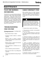
MAINTENANCE
FAULT AND WARNING
INFORMATION
The MicroPak 2e controller has been designed
to detect a number of high voltage and speed
related faults. These faults cause brief fault
descriptions (14 characters or less) to be displayed on either the High Voltage or Atomizer
display screen. If the reader requires further
clarification regarding a particular fault they
should refer to the “MicroPak 2e HV & Atomizer Controller” manual, Ransburg number LN9624-00 for further details.
TROUBLESHOOTING
HIGH VOLTAGE
Following are some areas to investigate when
high voltage faults occur:
Dirty atomizer interior or exterior.
CABLE CONTINUITY TEST
When problems arise, the Cable Continuity
Test can be performed to help determine
whether the problem is with the MicroPak 2e
HV controller or the cable and/or cascade assembly
!
WARNING
Because this test involves access to
the interior of the MicroPak 2e Single Bell
controller cabinet, where hazardous voltages may be present, it should only be performed by qualified electronics technicians.
To conduct the test, perform the following:
1. Ensure that the controller is disconnected
from the AC source.
2. Using the supplied cabinet key, unlock and
open top panel of the controller cabinet (see
Figure 15).
Conductive solvent residue on atomizer
assembly.
Moisture inside or outside of atomizer
body, causing continuity or partial continuity back to ground.
Moisture inside or outside of air lines back
to ground (high humidity).
Loose connections or defective low volt-
age cable.
Loose or defective ground connections.
Dump lines not clean or dry leading back
3. Disconnect connector J7 (see Figure 16)
from the rear of the problem MicroPak 2e HV
controller. Leave the other end of the Low
Voltage Cable connected to the atomizer being used.
4. Using an ohmmeter, measure the resistance values between the wires of MicroPak
connector J7. The readings should be as
shown in Table 2. If any of the readings are
significantly outside the values listed in Table
2, the low voltage cable and/or cascade
should be checked for the cause of the problem. Otherwise, the cause of the problem is
most likely the controller.
to ground.
Target not grounded and causing arcing to
5. Reconnect connector J7 and close and relock the cover of the controller cabinet.
ground.
26
LN-9625-00
MicroPak 2e Single Bell Controller - Maintenance
CABINET
KEY LOCK
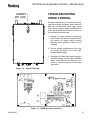
TROUBLESHOOTING
SPEED CONTROL
During troubleshooting it is important to recognize the automatic shutdown modes and consider the circumstances which might cause
them. Some common system problems which
cause the MicroPak 2e Atomizer Controller to
go to automatic shutdown are:
1. Bearing air supply pressure momentarily
drops below the required threshold when
the system air supply cannot maintain
pressure during periods of high air consumption.
2. Paint or solvent contamination in the rotator causing blockage of the fiber optic
speed feedback signal.
3. Damage to the fiber optic cable causing a
reduced intensity of the speed feedback
signal at the MicroPak 2e Atomizer Controller, i.e. reduced intensity from the fiber
optic cable.
Figure 15: Cabinet Top View
Figure 16: MP2E Connector Locations
LN-9625-00
27
MicroPak 2e Single Bell Controller - Maintenance
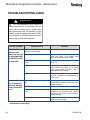
TROUBLESHOOTING GUIDE
!
WARNING
The “Troubleshooting Guide” below requires measurement of potentials that can
cause serious bodily injury if proper measuring procedures are not followed. For this
reason, proper troubleshooting should ONLY
be conducted by qualified electronics technicians using specific test equipment.
General Problem
MicroPak Power
Indicator and
Meters do not light
up when MicroPak
2e ON/OFF Switch
is turned ON
No or Low kV Output at Spray Gun
when HV ON Indicator (green LED)
is Lit
Possible Cause
Solution
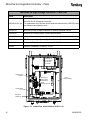
AC Power ON/OFF switch on rear of Turn AC power ON/OFF switch ON.
controller not turned ON.
Improper input line voltage.
Ensure voltage across terminals 2 and 3 of
CON1 (see Figure 17) of 24VDC power
supply is between 90 and 264 VAC.
Fuse of 24VDC power supply is de- Check fuse and replace if defective (see
fective.
Figure 17).
Defective 24VDC power supply.
Voltage across terminals 1 and 8 of connector CON2 (see Figure 17) of 24VDC
power supply should be 24VDC. If not replace 24VDC power supply.
Defective MicroPak 2e Control Unit.
If none of the suggestions above resolves
the issue, replace the A13338 MicroPak 2e
Control Unit.
High voltage is not set to proper val- Set the high voltage setpoint using either
ue.
the EtherNet/IP interface or the front panel
operator interface.
Local/remote switch in wrong position. Put local/remote switch in proper position.
Defective atomizer or low voltage
cable.
Perform a Cable Continuity Test. If proper
readings are not obtained, check cable or
atomizer for cause (see current “Atomizer”
Service Manual).
Loose or broken wire in power supply. Check all wiring connections for integrity.
Repair wiring as needed.
(Continued On Next Page)
28
LN-9625-00
MicroPak 2e Single Bell Controller - Maintenance
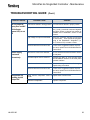
TROUBLESHOOTING GUIDE
General Problem
No kV Output at
Spray Gun and HV
ON Indicator
(green LED) is not
Lit
Power Supply
Overloads
Excessively
Component not
working, but kV
Output OK
LN-9625-00
(Cont.)
Possible Cause
Solution
Local/remote switch in wrong position. Put local/remote switch in proper position.
Improper interlock connection.
Ensure enabled interlock connections have
the (+) and (-) terminals connected together
through a jumper or voltage free contact as
detailed in the “Installation” section of this
manual.
High Voltage On input not activated.
Verify the controller operates as expected
in local mode. Then review the programming of the EtherNet/IP “Originator” (i.e.
PLC, Robot or PC) to locate a cause.
Defective MicroPak 2e Control Unit.
If none of the suggestions above resolves
the issue, replace the A13338 MicroPak 2e
Control Unit.
Parts are too close to the atomizer.
Ensure sufficient distance between atomizer and parts.
Overload setpoint set too sensitive.
Increase the Max uA Limit through either
the EtherNet/IP interface or the front panel
operator interface.
Defective atomizer or cable.
Check all wiring connections for integrity.
Repair wiring as needed.
Defective MicroPak 2e Control Unit.
If none of the suggestions above resolves
the issue, replace the A13338 MicroPak 2e
Control Unit.
Wiring to/from component loose or Repair loose or broken wire.
broken.
Defective component.
Replace component.
29
MicroPak 2e Single Bell Controller - Maintenance
TROUBLESHOOTING GUIDE
(Cont.)
Table 2. Ohm meter Measurements in Ohms from MicroPak 2e
Connector J7 through the Low Voltage Cable to the HP404 Cascade.
Signal
From Wire
IFB
2 (white)
Vct
3 (red)
Vct
4 (black)
HP_DrB
5 (green)
HP_DrA
6 (blue)
SigGnd
kVFB
VctRet
9 (grn/yel)
10 (gray)
16 (bare)
To Wire
2 (white)
3 (red)
4 (black)
5 (green)
6 (blue)
9 (grn/yel)
XX
open ckt.
open ckt
open ckt
open ckt
19K - 21K
400K-600K
open ckt
XX
0-3
0-3
0-3
open ckt
open ckt
open ckt *
XX
0-3
0-3
open ckt
open ckt
open ckt *
XX
0-3
open ckt
open ckt
open ckt *
XX
open ckt
open ckt
open ckt *
XX
400K-600K
open ckt
XX
open ckt
10 (gray)
16 (bare)
XX
* - Meter reading may vary in the megohms range due to capacitance across pins.
Figure 17: View of CON1, CON2 and Fuse
30
LN-9625-00
MicroPak 2e Single Bell Controller - Maintenance
LN-9625-00
31
MicroPak 2e Single Bell Controller - Parts
MicroPak 2e High Voltage Controller - Parts List
Part #
Description
A13338-XX XX XX
MicroPak 2e HV & Atomizer Controller
For replacement use, the user should order the same model (-XXXXXX) that
was listed on the original invoice.
A13245-00
MicroPak 2e High Voltage Controller PC Board—Atomizer Control
A13248-00
MicroPak 2e Analog Output, 4-20mA add-on board
A11111-00
Volume Booster, 1:1
78643-00
E/P Transducer, High Speed, High Flow, DIN Rail Mount, 0-10V : 0-100PSI
A11485-00
Pneumatic Solenoid, minimum 4mm bore, 0-120 PSI
A13596
Pressure Transducer, 0-100 PSI : 0-10V
MicroPak 2e
High Voltage
& Atomizer
Controller
Brake Control
Solenoid
MicroPak 2e
High Voltage
Controller PC
Board
Atomizer Control
24 DC
Power Supply
Turbine Speed
E-to-P
Bearing Air
Transducer
Figure 18: Inside View A13613-00 and A13613-–01
32
LN-9625-00
MicroPak 2e Single Bell Controller - Parts
MicroPak 2e
High Voltage
& Atomizer
Controller
24 DC
Power Supply
Figure 19: Inside View A13613-02
NOTES
LN-9625-00
33
MicroPak 2e Single Bell Controller - Warranty Policies
WARRANTY POLICIES
LIMITED WARRANTY
Ransburg will replace or repair without charge
any part and/or equipment that falls within the
specified time (see below) because of faulty
workmanship or material, provided that the
equipment has been used and maintained in
accordance with Ransburg's written safety and
operating instructions, and has been used
under normal operating conditions. Normal
wear items are excluded.
THE USE OF OTHER THAN RANSBURG
APPROVED PARTS, VOID ALL WARRANTIES.
SPARE PARTS: One hundred and eighty (180)
days from date of purchase, except for rebuilt
parts (any part number ending in "R") for which
the warranty period is ninety (90) days.
EQUIPMENT: When purchased as a complete
unit, (i.e., guns, power supplies, control units,
etc.), is one (1) year from date of purchase.
RANSBURG'S ONLY OBLIGATION UNDER THIS WARRANTY IS TO REPLACE
PARTS THAT HAVE FAILED BECAUSE
OF FAULTY WORKMANSHIP OR MATERIALS. THERE ARE NO IMPLIED WARRANTIES NOR WARRANTIES OF EITHER
MERCHANTABILITY OR FITNESS FOR A
PARTICULAR PURPOSE.
RANSBURG
ASSUMES NO LIABILITY FOR INJURY,
DAMAGE TO PROPERTY OR FOR CONSEQUENTIAL DAMAGES FOR LOSS OF
GOODWILL OR PRODUCTION OR INCOME, WHICH RESULT FROM USE OR
MISUSE OF THE EQUIPMENT BY PURCHASER OR OTHERS.
EXCLUSIONS:
If, in Ransburg's opinion the warranty item in
question, or other items damaged by this
part was improperly installed, operated or
maintained, Ransburg will assume no
responsibility for repair or replacement of the
item or items. The purchaser, therefore will
assume all responsibility for any cost of
repair or replacement and service related
costs if applicable.
WRAPPING THE APPLICATOR, ASSOCIATED VALVES AND TUBING, AND SUPPORTING HARDWARE IN PLASTIC, SHRINK
-WRAP, OR ANY OTHER NON-APPROVED
COVERING, WILL VOID THIS WARRANTY.
34
LN-9625-00
MicroPak 2e Single Bell Controller - Warranty Policies
LN-9625-00
35
Manufacturing
1910 North Wayne Street
Angola, Indiana 46703-9100
Telephone: 260-665-8800
Fax: 260-665-8516
Technical Service — Assistance
320 Philips Ave.
Toledo, Ohio 43612-1493
Telephone (toll free): 800-233-3366
Fax: 419-470-2233
Technical Support Representative will direct you to the appropriate telephone number for
ordering Spare Parts.
© 2014 Ransburg. All rights reserved.
Models and specifications subject to change without notice.
Form No. LN-9625-00
Litho in U.S.A.
03/14