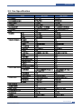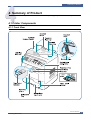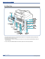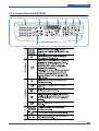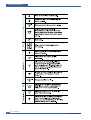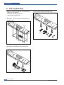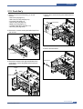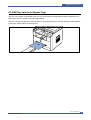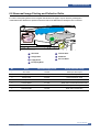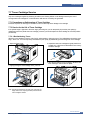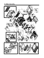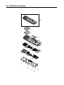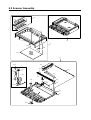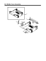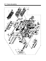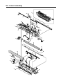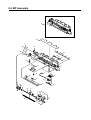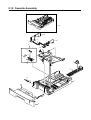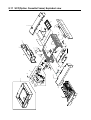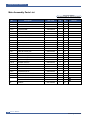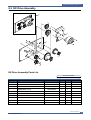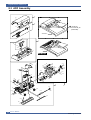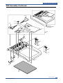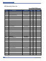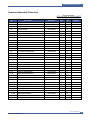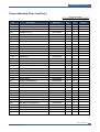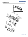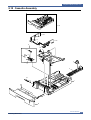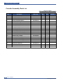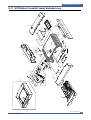
1
DIGITAL LASER MFP SCX-4720F Series SCX-4720FN/XAA Basic Model : SCX-4720F SERVICE Manual DIGITAL LASER MFP CONTENTS [ Key Features] - Network Standard (Network Printing, Network Scanning) - Direct USB Features ( Print from USB device, Scan to USB device) - 20 ppm Print/Copy Speed (14 ppm MDSP) - 1200 dpi Print Resolution - PCL6 - 64 MB System Memory - 50 ADF - 250 sh Paper Input (additional 250x1 Tray) - 50 sh MP Tray - 150 sh Paper Output - 33.6 Kbps Fax Modem - 200 Speed Dial Precautions 1 1. Precautions In order to prevent accidents and to prevent damage to the equipment please read the precautions listed below carefully before servicing the printer and follow them closely. 1.1 Safety Warning (1) Only to be serviced by appropriately qualified service engineers. High voltages and lasers inside this product are dangerous. This printer should only be serviced by a suitably trained and qualified service engineer. (2) Use only Samsung replacement parts There are no user serviceable parts inside the printer. Do not make any unauthorized changes or additions to the printer, these could cause the printer to malfunction and create electric shock or fire hazards. (3) Laser Safety Statement The Printer is certified in the U.S. to conform to the requirements of DHHS 21 CFR, chapter 1 Subchapter J for Class 1(1) laser products, and elsewhere, it is certified as a Class I laser product conforming to the requirements of IEC 825. Class I laser products are not considered to be hazardous. The laser system and printer are designed so there is never any human access to laser radiation above a Class I level during normal operation, user maintenance, or prescribed service condition. Warning >> Never operate or service the printer with the protective cover removed from Laser/Scanner assembly. The reflected beam, although invisible, can damage your eyes. When using this product, these basic safety pre-cautions should always be followed to reduce risk of fire, electric shock, and injury to persons. CAUTION - INVISIBLE LASER RADIATION WHEN THIS COVER OPEN. DO NOT OPEN THIS COVER. VORSICHT - UNSICHTBARE LASERSTRAHLUNG, WENN ABDECKUNG GE FFNET. NICHT DEM STRAHL AUSSETZEN. ATTENTION - RAYONNEMENT LASER INVISIBLE EN CAS D OUVERTURE. EXPOSITION DANGEREUSE AU FAISCEAU. ATTENZIONE - RADIAZIONE LASER INVISIBILE IN CASO DI APERTURA. EVITARE L ESPOSIZIONE AL FASCIO. PRECAUCION - RADIACION LASER IVISIBLE CUANDO SE ABRE. EVITAR EXPONERSE AL RAYO. ADVARSEL. - USYNLIG LASERSTR LNING VED BNING, N R SIKKERHEDSBRYDERE ER UDE AF FUNKTION. UNDG UDSAETTELSE FOR STR LNING. ADVARSEL. - USYNLIG LASERSTR LNING N R DEKSEL PNES. STIRR IKKE INN I STR LEN. UNNG EKSPONERING FOR STR LEN. VARNING - OSYNLIG LASERSTR LNING N R DENNA DEL R PPNAD OCH SP RREN R URKOPPLAD. BETRAKTA EJ STR LEN. STR LEN R FARLIG. VARO! - AVATTAESSA JA SUOJALUKITUS OHITETTAESSA OLET ALTTIINA N KYM TT M LLE LASERS TEILYLLE L KATSO S TEESEEN. Service Manual Samsung Electronics 1-1 Precautions 1.2 Caution for safety 1.2.1 Toxic material This product contains toxic materials that could cause illness if ingested. (1) If the LCD control panel is damaged it is possible for the liquid inside to leak. This liquid is toxic. Contact with the skin should be avoided, wash any splashes from eyes or skin immediately and contact your doctor. If the liquid gets into the mouth or is swallowed see a doctor immediately. (2) Please keep toner cartridges away from children. The toner powder contained in the toner cartridge may be harmful and if swallowed you should contact a doctor. 1.2.2 Electric Shock and Fire Safety Precautions Failure to follow the following instructions could cause electric shock or potentially cause a fire. (1) Use only the correct voltage, failure to do so could damage the printer and potentially cause a fire or electric shock. (2) Use only the power cable supplied with the printer. Use of an incorrectly specified cable could cause the cable to overheat and potentially cause a fire. (3) Do not overload the power socket, this could lead to overheating of the cables inside the wall and could lead to a fire. (4) Do not allow water or other liquids to spill into the printer, this can cause electric shock. Do not allow paper clips, pins or other foreign objects to fall into the printer these could cause a short circuit leading to an electric shock or fire hazard.. (5) Never touch the plugs on either end of the power cable with wet hands, this can cause electric shock. When servicing the printer remove the power plug from the wall socket. (6) Use caution when inserting or removing the power connector. The power connector must be inserted completely otherwise a poor contact could cause overheating possibly leading to a fire. When removing the power connector grip it firmly and pull. (7) Take care of the power cable. Do not allow it to become twisted, bent sharply round corners or otherwise damaged. Do not place objects on top of the power cable. If the power cable is damaged it could overheat and cause a fire or exposed cables could cause an electric shock. Replace a damaged power cable immediately, do not reuse or repair the damaged cable. Some chemicals can attack the coating on the power cable, weakening the cover or exposing cables causing fire and shock risks. (8) Ensure that the power sockets and plugs are not cracked or broken in any way. Any such defects should be repaired immediately. Take care not to cut or damage the power cable or plugs when moving the machine. (9) Use caution during thunder or lightening storms. Samsung recommend that this machine be disconnected from the power source when such weather conditions are expected. Do not touch the machine or the power cord if it is still connected to the wall socket in these weather conditions. (10) Avoid damp or dusty areas, install the printer in a clean well ventilated location. Do not position the machine near a humidifier. Damp and dust build up inside the machine can lead to overheating and cause a fire. (11) Do not position the printer in direct sunlight. This will cause the temperature inside the printer to rise possibly leading to the printer failing to work properly and in extreme conditions could lead to a fire. (12) Do not insert any metal objects into the machine through the ventilator fan or other part of the casing, it could make contact with a high voltage conductor inside the machine and cause an electric shock. 1-2 Service Manual Samsung Electronics Precautions 1.2.3 Handling Precautions The following instructions are for your own personal safety, to avoid injury and so as not to damage the printer (1) Ensure the printer is installed on a level surface, capable of supporting its weight. Failure to do so could cause the printer to tip or fall. (2) The printer contains many rollers, gears and fans. Take great care to ensure that you do not catch your fingers, hair or clothing in any of these rotating devices. (3) Do not place any small metal objects, containers of water, chemicals or other liquids close to the printer which if spilled could get into the machine and cause damage or a shock or fire hazard. (4) Do not install the machine in areas with high dust or moisture levels, beside on open window or close to a humidifier or heater. Damage could be caused to the printer in such areas. (5) Do not place candles, burning cigarettes, etc. on the printer, these could cause a fire. 1.2.4 Assembly / Disassembly Precautions Replace parts carefully, always use Samsung parts. Take care to note the exact location of parts and also cable routing before dismantling any part of the machine. Ensure all parts and cables are replaced correctly. Please carry out the following procedures before dismantling the printer or replacing any parts. (1) Check the contents of the machine memory and make a note of any user settings. These will be erased if the mainboard or network card is replaced. (2) Ensure that power is disconnected before servicing or replacing any electrical parts. (3) Disconnect printer interface cables and power cables. (4) Only use approved spare parts. Ensure that part number, product name, any voltage, current or temperature rating are correct. (5) When removing or re-fitting any parts do not use excessive force, especially when fitting screws into plastic. (6) Take care not to drop any small parts into the machine. (7) Handling of the OPC Drum - The OPC Drum can be irreparably damaged if it exposed to light. Take care not to expose the OPC Drum either to direct sunlight or to fluorescent or incandescent room lighting. Exposure for as little as 5 mins can damage the surface’s photoconductive properties and will result in print quality degradation. Take extra care when servicing the printer. Remove the OPC Drum and store it in a black bag or other lightproof container. Take care when working with the covers(especially the top cover) open as light is admitted to the OPC area and can damage the OPC Drum. - Take care not to scratch the green surface of OPC Drum Unit. If the green surface of the Drum Cartridge is scratched or touched the print quality will be compromised. Service Manual Samsung Electronics 1-3 Precautions 1.2.5 Disregarding this warning may cause bodily injury (1) Be careful with the high temperature part. The fuser unit works at a high temperature. Use caution when working on the printer. Wait for the fuser to cool down before disassembly. (2) Do not put finger or hair into the rotating parts. When operating a printer, do not put hand or hair into the rotating parts (Paper feeding entrance, motor, fan, etc.). If do, you can get harm. (3) When you move the printer. This printer weighs 17kg including toner cartridge and cassette. Use safe lifting and handling techniques. Use the lifting handles located on each side of the machine. Back injury could be caused if you do not lift carefully. (4) Ensure the printer is installed safely. The printer weighs 17Kg, ensure the printer is installed on a level surface, capable of supporting its weight. Failure to do so could cause the printer to tip or fall possibly causing personal injury or damaging the printer. (5) Do not install the printer on a sloping or unstable surface. After installation, double check that the printer is stable. 1-4 Service Manual Samsung Electronics Precautions 1.3 ESD Precautions Certain semiconductor devices can be easily damaged by static electricity. Such components are commonly called “Electrostatically Sensitive (ES) Devices”, or ESDs. Examples of typical ESDs are: integrated circuits, some field effect transistors, and semiconductor “chip” components. The techniques outlined below should be followed to help reduce the incidence of component damage caused by static electricity. Caution >>Be sure no power is applied to the chassis or circuit, and observe all other safety precautions. 1. Immediately before handling a semiconductor component or semiconductor-equipped assembly, drain off any electrostatic charge on your body by touching a known earth ground. Alternatively, employ a commercially available wrist strap device, which should be removed for your personal safety reasons prior to applying power to the unit under test. 2. After removing an electrical assembly equipped with ESDs, place the assembly on a conductive surface, such as aluminum or copper foil, or conductive foam, to prevent electrostatic charge buildup in the vicinity of the assembly. 3. Use only a grounded tip soldering iron to solder or desolder ESDs. 4. Use only an “anti-static” solder removal device. Some solder removal devices not classified as “anti-static” can generate electrical charges sufficient to damage ESDs. 5. Do not use Freon-propelled chemicals. When sprayed, these can generate electrical charges sufficient to damage ESDs. 6. Do not remove a replacement ESD from its protective packaging until immediately before installing it. Most replacement ESDs are packaged with all leads shorted together by conductive foam, aluminum foil, or a comparable conductive material. 7. Immediately before removing the protective shorting material from the leads of a replacement ESD, touch the protective material to the chassis or circuit assembly into which the device will be installed. 8. Maintain continuous electrical contact between the ESD and the assembly into which it will be installed, until completely plugged or soldered into the circuit. 9. Minimize bodily motions when handling unpackaged replacement ESDs. Normal motions, such as the brushing together of clothing fabric and lifting one’s foot from a carpeted floor, can generate static electricity sufficient to damage an ESD. 1.4 Super Capacitor or Lithium Battery Precautions 1. Exercise caution when replacing a super capacitor or Lithium battery. There could be a danger of explosion and subsequent operator injury and/or equipment damage if incorrectly installed. 3. Super capacitor or Lithium batteries contain toxic substances and should not be opened, crushed, or burned for disposal. 2. Be sure to replace the battery with the same or equivalent type recommended by the manufacturer. 4. Dispose of used batteries according to the manufacture’s instructions. Service Manual Samsung Electronics 1-5 Reference Information 2 2. Reference Information This chapter contains the tools list, list of abbreviations used in this manual, and a guide to the location space required when installing the printer. A definition of test pages and Wireless Network information definition is also included. 2.1 Tool for Troubleshooting The following tools are recommended safe and easy troubleshooting as described in this service manual. • DVM (Digital Volt Meter) Standard : Indicates more than 3 digits. • Driver Standard : "-" type, "+" type (M3 long, M3 short, M2 long, M2 short). • Cleaning Equipments Standard : An IPA (Isopropyl Alcohol) dry wipe tissue or a gentle neutral detergent and lint-free cloth. • Vacuum Cleaner • Spring Hook Standard : For general use • Tweezers Standard : For general home use, small type. • Cotton Swab Standard : For general home use, for medical service. • Software (Driver) installation CD ROM Service Manual Samsung Electronics 2-1 Reference Information 2.2 Acronyms and Abbreviations The table in the below explains abbreviations used in this service manual. The contents of this service manual are declared with abbreviations in many parts. Please refer to the table. AC Alternating Current IC integrated circuit ADF Automatic Document Feeder IDE ASIC Application Specific Integrated Circuit Intelligent Drive electronics or Imbedded Drive Electronics ASSY assembly IEEE Institute of Electrical and Electronics Engineers. Inc BIOS Basic Input Output System IPA Isopropy Alcohol CCD Charge Coupled Device IPM Images Per Minute CMOS Complementary Metal Oxide Semiconductor LAN local area network CN connector lb pound(s) CON connector LBP Laser Beam Printer CPU Central Processing Unit LCD Liquid Crystal Display CRUM Customer Replaceable Unit Memory LED Light Emitting Diode dB decibel LSU Laser Scanning Unit dbA decibelampere MB Megabyte dBM decibel milliwatt MFP Multi-Functional Product DC direct current MHz Megahertz DCU Diagnostic Control Unit NVRAM Nonvolatile random access memory DPI Dot Per Inch OPC Organic Photo Conductor DRAM Dynamic Random Access Memory PBA Printed Board Assembly DVM Digital Voltmeter PCL ECP Enhanced Capability Port Printer Command Language , Printer Control Language PDL Page Discription Language PPM Page Per Minute PTL Pre-Transfer Lamp Q’ty Quantity RAM Random Access Memory ROM Read Only Memory SCF Second Cassette Feeder SMPS Switching Mode Power Supply SPGP Samsung Printer Graphic Processor SPL Samsung Printer Language Spool Simultaneous Peripheral Operation Online SW Switch Sync Synchronous or synchronization TBD To Be Determined USB Universal Serial Bus EEPROM Electronically Erasable Programmable Read Only Memory 2-2 EMI Electro Magnetic Interference EP electrophotographic EPP Enhanced Parallel Port FCOT First Copy Out Time F/W firmware GDI graphics device interface GND ground HBP Host Based Printing HDD Hard Disk Drive HV high voltage HVPS High Voltage Power Supply I/F interface I/O Input and Output Service Manual Samsung Electronics Reference Information 2.3 The Sample Pattern for the Test The sample pattern shown in below is the standard pattern used in the factory. The life of the toner cartridge and the printing speed are measured using the pattern shown below. (The image is 70% of the actual A4 size). 2.3.1 A4 ISO 19752 Standard Pattern This test page is reproduced at 70% of the normal A4 size Service Manual Samsung Electronics 2-3 Reference Information 2.4 Wireless LAN • This product uses a printing function with a wireless LAN, which is an option. - The wireless LAN function uses a frequency instead of connecting LAN cable to connect data to an access point for print. - For a wireless LAN connection, an AP is needed, It is possible to use wireless LAN onnection with wired LAN. Also, if AP is installed in an office or at home, the wireless LAN function can be simply used. • Types of desk top PC (or Lap top) that uses the wireless LAN. Division Basic type Recommend type CPU Over PENTIUM 233M PENTIUM 300MHz MEMORY Over 64MB Over 128MB VIDEO CARD Over 800X600 Over 1024X768 OS Over WINDOWS 98 Over WINDOWS ME INTERFACE CARD A product has a certificated mark of Wi-FiTM • About the certificated mark of Wi-FiTM - The Wi-FiTM is a registered trademark of WECA (Wireless Ethernet Compatibility Alliance). Over 50 of a wireless LAN companies are member of it. The most of main wireless networking companies are attending and the main companies are Lucent technologies, Cisco, Intel/Symbol, 3Com, Enterasys (Cabletron), Compaq, IBM, Nokia, Dell, Philips, Samsung electronic, Sony, Intersil, and so on. This mark certifies mutual compatibility among product has Wi-FiTM (IEEE 802.1) and it is certified as a standard of a wireless LAN market. 2-4 Service Manual Samsung Electronics Specifications 3 3. Specifications Specfications are correct at the time of printing. Product specifications are subject to change without notice. See below for product specifications. 3.1 General Specifications Items SCX-4720F SCX-4720FN Service Manual Samsung Electronics 3-1 Specifications 3.2 Print Specification Items 3-2 SCX-4720F SCX-4720FN Service Manual Samsung Electronics Specifications 3.3 Scan Specification Items SCX-4720F SCX-4720FN Service Manual Samsung Electronics 3-3 Specifications 3.4 Copy Specification Items 3-4 SCX-4720F SCX-4720FN Service Manual Samsung Electronics Specifications 3.5 Fax Specification Items SCX-4720F SCX-4720FN Service Manual Samsung Electronics 3-5 Specifications (Continued) Items SCX-4720F SCX-4720FN SCX-4720F SCX-4720FN 3.6 Paper Handling Items 3-6 Service Manual Samsung Electronics Specifications 3.7 Software Items SCX-4720F SCX-4720FN Items SCX-4720F SCX-4720FN 3.8 Options Service Manual Samsung Electronics 3-7 Specifications 3.9 Consumables Items 3-8 SCX-4720F SCX-4720FN Service Manual Samsung Electronics Summary of Product 4 4. Summary of Product This chapter describes the functions and operating principal of the main components. 4.1 Printer Components 4.1.1 Front View Service Manual Samsung Electronics 4-1 Summary of Product 4.1.2 Rear View * This wireless network antenna is not supplied with the machine. It is an option that must be purchased and installed separately. (Option Function) ** The network port is not fitted as standard on the machine. You can purchase an optional Network Card and install it separately. *** If your country has a different telephone connection system, this socket may be blocked. 4-2 Service Manual Samsung Electronics Summary of Product 4.1.3 Control Panel (SCX-4720FN) Service Manual Samsung Electronics 4-3 Summary of Product 4-4 Service Manual Samsung Electronics Summary of Product 4.2 System Layout The SCX-4720F/4520 is roughly made up Main Control part, Operation Panel part, Scanner part, Line Interface part and Power part. Each Part is separated Module which focus on common and standard design of different kind products. main control part adopting Fax & LBP Printer exclusive Controller is composed of 2 CPU and 1 Board. Scanner part is composed of ADF and Platen and is connected with Main by Harness. 4.2.1 Feeding section There is a universal cassette which automatically loads paper and the manual feed which supplies paper single sheet at a time. The cassette has a friction pad which separates paper to ensure single sheet feeding, and it has a sensor, which checks when the paper tray is empty. - Feeding Method: Universal Cassette Type - Feeding Standard: Center Loading - Feeding Capacity: Cassette-250 sheets (75g/m2, 20lb paper standard) Manual 1 sheet (Paper, OHP, Envelop, etc.) - Paper detecting sensor: Photo sensor - Paper size sensor: None 4.2.2 Transfer Ass’y This consists of the PTL (pre-transfer lamp) and the Transfer Roller. The PTL shines a light onto the OPC drum. This lowers the charge on the drum’s surface and improves transfer efficiency. The transfer roller transfers toner from the OPC drum surface to the paper. - Life expectancy: Over 60,000 sheets (at 15~30°C) 4.2.3 Driver Ass’y - Gear driven power unit. The motor supplies power to the paper feed unit, the fuser unit, and the toner cartridge. 4.2.4 Fixing Part(Fuser) - The fuser consists of the Heat Lamp, Heat Roller, Pressure Roller, Thermistor, and Thermostat. It fixes toner to the paper using pressure and heat to complete the printing job. 4.2.4.1 Temperature-Intercepting Device (Thermostat) The thermostat is a temperature sensing device, which cuts off the power to the heat lamp to prevent overheating fire when the heat lamp or heat roller overheats. 4.2.4.2 Temperature Detecting Sensor (Thermistor) The Thermistor detects the surface temperature of the heat roller, this information is sent to the main processor which uses this information to regulate the temperature of the heat roller. 4.2.4.3 Heat Roller The surface of the Heat Roller is heated by the Heat Lamp. As the paper passes between the Heat and Pressure rollers the toner is melted and fixed permanently to the paper. The surface of the roller is coated with Teflon. This ensures that toner does not adhere to the roller surface. Service Manual Samsung Electronics 4-5 Summary of Product 4.2.4.4 Pressure roller The Pressure Roller mounted under the heat roller, it is made of a silicon resin, and the surface of the roller is coated with Teflon. This ensures that toner does not adhere to the roller surface. 4.2.4.5 Safety Features • To prevent overheating - 1st protection device: Hardware cuts off when overheated - 2nd protection device: Software cuts off when overheated - 3rd protection device: Thermostat cuts off mains power to the lamp. • Safety device - Fuser power is cut off when the front cover is opened - LSU power is cut off when the front cover is opened - The temperature of the fuser cover's surface is maintained at less than 80ºC to protect the user and a caution label is attached where the customer can see it easily when the rear cover is opened. 4.2.5 Scanner This image is read using a photosensitive sensor. It consists of a CCD module, Connection board, ADF board, AFE (Analog Front End), Image Processor (Located in CPU), platen glass and ADF mechanism. • CCD Module Specification 1.Resolution: 600dpi/A4 2.Maximum scan wide: 8.5” 3.Color filter: Red, Green, Blue 4.Output channel: 3 channels (R, G, B) 5.Effective pixel: 5,400 pixel *3 6.Voltage: 24V & 5V 7.Pre-heating time: Maximum 30 seconds (70% of light output reached) 8.The life span of a lamp: 30,000 hours (25oC) • Image Processor Specification 1.Operating frequency: 66MHz 2.Image sensor interface: 200/300/600 dpi CIS or CCD 3.Line time: Copy, FAX, Binary (Lineart, Halftone) PC Scan: 1.5ms/Line Color PC Scan (Grey, 256 Color, True Color): 4.5ms/Line 4.A/D conversion: 10bit conversion 4-6 Service Manual Samsung Electronics Summary of Product 4.2.6 LSU (Laser Scanner Unit) This is the core of the laser printer. It converts the video data received from the computer into an electrostatic latent image on the surface of the OPC drum. This is achieved by controlling the laser beam and exposing the surface of the OPC drum to the laser light. A rotating polygon mirror reflects the laser light onto the OPC and each side of the mirror is one scan line. The OPC drum turns as the paper feeds to scan the image down the page. The /HSYNC signal is created when the laser beam from LSU reaches the end of the polygon mirror and this signal is sent to the controller. The controller detects the /HSYNC signal to adjust the vertical line of the image on paper. In other words after the /HSYNC signal is detected the image data is sent to the LSU to adjust the left margin on the paper. Service Manual Samsung Electronics 4-7 Summary of Product 4.2.7 Toner Cartridge The toner cartridge is an integral unit containing the OPC unit and toner unit. The OPC unit consists of the OPC drum and charging roller, and the toner cartridge unit consists of the toner, supply roller, developing roller, and blade (Doctor blade) - Developing Method: Non magnetic 1 element contacting method - Toner: Non magnetic 1 element shatter type toner - The life span of toner: 3,000 sheets (ISO 19752) - Toner remaining amount detecting sensor: Yes - OPC Cleaning: Electrostatic process - Management of waste toner: Collect the toner using a Cleaning Blade - OPC Drum protecting Shutter: Yes - Classifying device for toner cartridge: ID is classified by interruption of the frame channel -430V -950V -580V 4-8 Service Manual Samsung Electronics Summary of Product 4.3 System Description 4.3.1 Overview SCX-4720FN is roughly made up Main Control part, Operation Panel part, Scanner part, Line Interface part and Power part. Each Part is separated Module which focus on common and standard design of different kind products. main control part adopting Fax & LBP Printer exclusive Controller is composed of 2 CPU and 1 Board. Scanner part is composed of ADF and Platen and is connected with Main by Harness . Line Interface part is designed to apply TBR21 standard(Domestic,Europe,etc..) 4.3.2 CPU Part 1) CPU : Use 32Bit RISC Processor, ARM946ES,which is exclusive controller to execute Printer FAX Function and to execute operation block by flash memory within system program, and to control whole system. - Main function block - Completely Integrated System for Embedded Applications, - 32 Bit Risc Architecture, Efficient and Powerful ARM9 Core. - LSU Interface Module for Interfacing PVC or HPVC with LSU - 2 Channel General Purpose DMA Controller for High Speed I/O - Dual Memory Bus Architecture - Operation Frequency : AHB Bus: 60MHz, Internal System Bus: 120MHz - Operation Voltage : 3.3V - POWER ON RESET TIME : Below 5.6ms 2) Flash Memory : Record System Program, and download System Program by PC INTERFACE. - FAX for Journal List, and Memory for One Touch Dial, Speed Dial List. - size : 4M Byte - Access Time : 70 nsec 3) SDRAM : is used as Swath Buffer in Printing, Scan Buffer in Scanning, ECM Buffer in FAX receiving, and System Working Memory Area - size 64MB : 64Mbyte(Basic). TBD MB : System Working Memory Area and Scan Buffer TBD MB : FAX Memory Receive Area TBD MB : Printing System Working Memory Area - Max Frequency : 133MHz - store Fax Receive Memory Data by using Battery Service Manual Samsung Electronics 4-9 Summary of Product 4.3.3 Fax Part 1) Modem Part <BLOCK DIAGRAM> DSP SSD System Side Transfrom CX20493 LSD Line Side Ext Line Capacito Primary Parts Implemented by based on Conexant DAA (Data Access Arrangement) Solution , and is roughly composed of two kinds Chip Solution - CX82500(SFM336) : Existing Modem Chip which adds SSD (System Side Device) for interfacing between - LSD and DIB of FM336Plus Core - CX20493(LSD) : LIU (Line Interface Unit) Chip which is controlled by SSD and satisfies each PSTN requirements by modulating internal Configuration with connecting Tel Line. Parallel synchronous data TTL and CMOS compatible DTE interface ITU-T V.24 (EIA/TIA-232-E) (data/control) Microprocessor bus (data/configuration/control) 2) there is A/D, D/A Converter in LSD, so Analog Signal from Tel Line is transited in Digital through A/D Converter in DAA and transfer to SSD by DIB Capacitor Digital Signal from SSD is converted to Analog by D/A Converter in DAA and transfer to Tel Line DSP SSD System Side Transfrom CX20493 LSD Line Side Ext Line Capacito Primary Parts 4-10 Service Manual Samsung Electronics Summary of Product 4.3.4 Scan Part Scan Part Pictorial signal input part : output signal of CCD passes through Bypass_Cap change to ADC at AFE_CIP4 , and defined signal between AFE_CIP4 and CIP4 processes the Image signal. When AFE accept each pixel, CDS(Correlated Double Sampling ) technique which samples arm-level twice is used on each pixel by using CIP4 signal. 1) Pictorial image processing part : read CCD Pixel data in terms of 600dpi Line and process LAT algorithm on Text mode, Error Diffusion Algorithm on Mixed mode, and store Data at Scan Buffer on PC Scan mode without algorithm. on every mode Shading Correction and Gamma Correction are executed ahead, then processing is executed later. * Scan Image Control Specification Minimum Scan Line Time : 0.72ms Scan Resolution : Max. 600DPI Scan Width : 216mm main function - Internal 12bit ADC - White Shading Correction - Gamma Correction - CCD Interface - 256 Gray Scale 2) CCD Operating Part : CCD Image sensor use +5V and Inverter uses +24V - CCD Maximum Operating Frequency : 10MHz - CCD Line time : 0.72ms - White Data output Voltage : 0.7V 0.5V (Mono Copy, 0.72ms/line) - Maximum Inverter Current : 600 mA Max.( +24V) Service Manual Samsung Electronics 4-11 Summary of Product 4.3.5 Printer Part Printer is consisted of the Engine parts and F/W, and said engine parts is consisted of the mechanical parts comprising Frame, Feeding, Developing, Driving, Transferring, Fusing, Cabinet and H/W comprising the main control board, power board, operation panel, PC Interface. The main controller is consisted of Asic(SPGPm) parts, Memory parts, Engine Interface parts and it functions as Bus Control, I/O Handling, drivers & PC Interface by CPU. Memory Access supports 16bit Operation, and Program Memory 2MB and Working Memory as well. The Engine Board and the Controller Board are in one united board, and it is consisted of CPU part and print part in functional aspect. The CPU is functioned as the bus control, I/O handling, drivers, and PC interface. The main board sends the Current Image, Video data to the LSU and manages the conduct of Electrophotography for printing. It is consisted of the circuits of the motor (paper feed, pass) driving, clutch driving, pre-transfer lamp driving, current driving, and fan driving. The signals from the paper feed jam sensor and paper empty sensor are directly inputted to the main board. 4.3.6 ASIC ASIC ARM946ES 32-bit RISC embedded processor core 16KB instruction cache and 16KB data cache No Tightly Coupled Memory Memory Protection Unit & CP15 control program Dual bus architecture for bus traffic distribution AMBA High performance Bus (AHB) System Bus with SDRAM Printer Video Controller for LBP engines Graphic Execution Unit for banding support of Printer Languages Printer Video Controller for LBP engines PVC : Printer Video Controller without RET Algorithm HPVC : Printer Video Controller with RET algorithm (Line Memory & Lookup Table Memory : 512 x 8 , 4096 x 16) Engine Controller Motor Control Unit Motor Speed Lookup Table Memory (128 x 16 x 2) Pulse Width Modulation Unit 4 Channels are supported ADC Interface Unit 3 ADC Channels are available ADC Core (ADC8MUX8) maximum clock frequency : 3 MHz USB 2.0 Interface Package : 272 pins PBGA Power : 1.8V(Core), 3.3V(IO) power operation 4-12 Service Manual Samsung Electronics Summary of Product Speed : 166MHz core(ARM946ES) operation, 60MHz bus operation Service Manual Samsung Electronics 4-13 Summary of Product 4.3.7 Sensor input circuit 1) Paper Empty Sensor The Paper Empty sensor (Photo Interrupter) on the SMPS/HVPS PBA (CON2-2) is monitored by the CPU on signal (nP_EMPTY). When the cassette is empty the printer displays a message on the LCD panel. 2) MP Sensing Presence of paper in the MP tray is detected by operation of the MP Sensor (Photo Interrupter) on the SMPS/HVPS PBA (CON2-14). The CPU monitors signal(MP_EMPTY) to recognize paper in the MP, and paper is fed from MP if there is paper present. 3) Paper Feed Sensor, (Toner Cartridge Sensor) When paper passes the actuator on the feed sensor (CON2-1), it is detected by the Photo interrupter. signal(nP_FEED) monitored by the CPU and this signal starts the process of creating the image after certain delay time If the feed sensor is not detected within 1 sec. after paper is fed, a paper Jam0 occurs. (Displayed on the LCD panel). When a toner cartridge is inserted it also operates the Paper Feed sensor. A message is displayed on the LCD if no cartridge is detected. 4) Paper Exit Sensor This detects that paper exits cleanly from the Machine using an exit sensor (CON2-24) on the engine board and actuator on the frame. The monitors signal (P_EXIT) and detects the on/off time of the exit sensor and if jam status is detected then JAM2 is displayed the on the LCD panel. 5) Cover Open Senser The Cover open sensor actuator is located on the front cover and the senor is in the main frame. When the front cover is opened the +24V supplies to the DC fan, solenoid, main motor, polygon motor part of LSU, HVPS that are cut off. The CPU monitors signal (COVER_OPEN) to recognize when the cover is opened. 6) DC FAN / SOLENOID Driving It is driven by a transistor and controlled by signal (FAN (SMPS, CON2-23)) bit of the CPU. When it is high the fan is activated by turning on the TR, and it is off when the sleep mode is selected. There are two solenoids and these are driven by the Paper Pick-up and MP signals. The drive time is 300ms. The diode protects the driving TR from the Back-EMF pulse which is generated when the solenoid is de-energized. 7) Motor Driving The motor driving circuit is activated when the Driver IC is enabled. An A3977 (Motor driver IC) is used in this case. The resistance Rs value of sensing and the voltage value of the V reference can be changed by the motor driving voltage value. 4-14 Service Manual Samsung Electronics Summary of Product 4.4 SMPS & HVPS The SMPS and HVPS are on one integrated board. The SMPS supplies the DC power to the system. It takes either 110V or 220V and outputs the +5V, +12V and +24V supplies to the main and other PBAs. The HVPS creates the high voltage of THV/MHV/Supply/Dev and supplies it to the toner cartridge. The CPU is used to modify some of these voltage settings to provide the ideal voltages to create the image. The HVPS part uses the 24V and outputs the high voltage for THV/MHV/BIAS and the outputted high voltage is supplied to the toner, OPC cartridge and transfer roller. Service Manual Samsung Electronics 4-15 Summary of Product 4.4.1 HVPS(High Voltage Power Supply) 1) Transfer High Voltage (THV+) - Function : It is this voltage that transfers toner from the OPC Drum to the paper. - Output voltage : +1300V DC±20V - Error : IF THV (+) is not present, low density printing occurs due to toner on the OPC Drum not being transferred to the paper. It is possible that waste toner over-flow can occur if this condition persists. Ghost images may appear which repeat at 76mm intervals. 2) Charge Voltage (MHV) - Function : It is this voltage that charges the surface of the OPC to -900V ~ -1000V. - Output voltage : -1550V DC ± 50V - Error : IF MHV is not present toner then since the OPC drum surface has no charge toner is attracted to the whole OPC surface. A black page is printed out when this happens. 3)Cleaning Voltage (THV-) - Function : It removes toner contamination from the rear side of the paper by sending (-) polarity to the transfer roller forcing toner to transfer back to the to OPC drum. - Output Voltage : -1200V, +300V/-150V - Error : Smudges and toner contamination on the reverse side of the printed page. 4) Developing Voltage (DEV) - Function: It is this voltage that develops toner with on to the section of the OPC drum surface exposed by the LSU (Laser Scanning Unit). * When printing the exposed voltage on the OPC is -180V, unexposed is -900~-1000V, and the exposing voltage on the DEV is -430V. Therefore toner with (-) polarity is developed onto an exposed section of the OPC. - Output voltage: -430V DC ± 20V - Error: a) If DEV is GND, print density gets extremely low. b) When DEV is floating due to poor connection between the frame and cartridge contacts etc., print density gets extremely high. 5) Supply Voltage (SUP) - Function: It is this voltage that supplies toner to the developing roller. - Output voltage: : -580V DC ± 50V (Use ZENER, DEV Gear) - Error: a) When SUP is GND print density gets extremely low. b) If SUP is floating due to poor connection between the frame and cartridge contacts etc. density gets extremely low such that it is hard to see toner with the eyes 6) OPC Ground ZENER Voltage - Function: It is this voltage that prevents image contamination under low temperature and low humidity environment conditions. - When a set prints without an output voltage, -130V DC ± 15V is maintained on OPC ground. (-103V ZENER diode is connected to OPC ground) - Error type: a) When the ZENER diode is - 0V there is no serious image problem in general environment, but in low temperature and low humidity environments it is possible that contamination can occur on the entire image b) When the ZENER diode is disconnected a blank page is printed out. (It is the same when a ZENER diode is disconnected from OPC ground.) 4-16 Service Manual Samsung Electronics Summary of Product 4.4.2 SMPS (Switching Mode Power Supply) This is the power source for the whole system. It is an independent module so that it is possible to use it for common use. It is mounted at the bottom of the set. It consists of the SMPS section, which supplies the DC power to drive the system, and the AC heater control part, which supplies the power to the fuser. The SMPS has four output channels (+5V, +24V and 24VS). There are three kinds of power, 120V exclusive (America), 220V exclusive (Europe), and 220V for China (nations with unstable power supply). 1) AC Input > Input Rated Voltage : AC 220V ~ 240V AC 120V / AC 220V(EXP version) > Input Voltage fluctuating range : AC 198V ~ 264V AC 90V ~ 135V / AC 198V ~ 264V > Rated Frequency : 50/60 Hz > Frequency Fluctuating range : 47 ~ 63 Hz > Input Current : Under 5.0Arms / 2.5Arms (When the fuser lamp is off and input / output voltages are in range) 2) Rated Output Power NO ITEM CH2 CH3 1 CHANNEL NAME +5V +24.0V 2 CONNECTOR PIN CON 3 CON 3 5V PIN: 8 24V PIN: 11,12,13 GND PIN: 7 GND PIN: 9,10 +5V & 5% +24V & 10% (4.75 to 5.25V) (21.6 to 26.4V) 3 Rated Output 4 Max. Output Current 0.14 A 2.0 A 5 Peak Loading Current 0.14 A 2.5 A 6 RIPPLE NOISE Voltage 100mVp-p Under 500mVp-p 7 Maximum Output Power 0.35W 48W 8 Peak Output Power 0.7W 60W 9 Protection for short circuit and current overload Remark 1ms 1ms - 3) Power Consumption NO ITEM CH2 (+5V) CH3 (+24V) Remark 1 Stand-By 0.07A 0.4 A AVG:55 Wh 2 PRINTING 0.14A 2.0 A AVG 350 Wh 3 Sleep-Mode 0.01A 0.4A AVG : 20 Wh 4) Length of Power Cord : 1830 ± 50mm 5) Power Switch : Fitted Service Manual Samsung Electronics 4-17 Summary of Product 6) Feature - Summary of Product Insulation resistance : over 50M Ω (at DC500V) Insulating retest pressure : Must be no problem within 1min. (at 1500Vzc, 10mA) Leakage current : under 3.5mA Operating current : under 40A peak (at 25°c, Cold start) Under 60A peak (in other conditions) Rise Time : Within 2Sec Fall Time : Over 20ms Surge : Ring Wave 6KV-500A (Normal, Common) 7) Environment Condition - Operating temperature range : 0°C ~ 40°C Storage temperature range : -25°C ~ 85°C Storage humidity range : 30% ~ 90% RH Operating atmospheric pressure range : 1 8) EMI Requirement : CISPR ,FCC, CE, MIC, C-Tick, 9) Safety Requirement - IEC950, C-UL, TUV,Semko,iK,CB, CCC, EPA, 4.4.3 Fuser AC Power Control The Fuser (HEAT LAMP) is heated using AC power. The AC power is controlled by a Triac (THY1), a semiconductor switch. 'On/Off control' is achieved when the gate of the Triac is turned on/off by a Photo triac (PC1), this is an insulting part. In the other words the AC control part is a passive circuit. It turns the heat lamp on/off by taking a signal from the engine control section. When the 'HEATER ON' signal is activated by the engine the LED of PC1 (Photo Triac) flashes. The flashing light causes the Triac (PC1) to switch and a voltage is supplied to the gate of Triac THY1. As a result AC current flows in the heat lamp, and heat is produced. On the other hand, when the signal is off, PC1 is off, the voltage is cut off at the gate of Triac THY1, this Triac is therefore off, and thus the heat lamp is turned off. 1) Triac (THY1) feature - 12A, 600V SWITCHING 2) Phototriac Coupler (PC3) - Turn On If Current : 15mA ~ 50mA(Design: 16mA) - High Repetive Peak Off State Voltage : Min 600V 4-18 Service Manual Samsung Electronics Summary of Product 4.5 Engine F/W 4.5.1 Feeding If feeding from the cassette the drive of the pickup roller is controlled by controlling the pick-up solenoid. The on/off of the solenoid is controlled by controlling the general output port or the external output port. If feeding from the manual feeder the set decides to feed the paper according to the operation of the manual sensor, and by driving the main motor, insert the paper in front of the feed sensor. When paper moves the occurrence of a paper jam is judged as below. 4.5.1.1 Jam 0 – Jam in Feed area • After a page was picked up, paper did not enter the unit due to a paper misfeed. • After a page was picked up, paper entered but it did not reach the feed sensor in certain time due to slip, etc. • After a page was picked up, if the feed sensor is not on try to pick up again. After retrying if the feed sensor is still not on after certain time, it is Jam 0. - this indicates that the leading edge of the paper doesn't pass the feed sensor within a certain time. • Even though the paper reaches the feed sensor, the feed sensor does not turn on. - this indicates that the leading edge of the paper already passed the feed sensor or that the sensor is fauty. 4.5.1.2 Jam 1 – Jam inside the print engine • After the leading edge of the paper passes the feed sensor, the trailing edge of the paper does not pass the feed sensor within certain time. (During this time the feed sensor cannot be Off) • After the leading edge of the paper passes the feed sensor, the paper does not reach the exit sensor within certain time. (The exit sensor cannot be On during this time) - There is already paper between the feed sensor and the exit sensor. 4.5.1.3 Jam 2 – Jam in the Exit area • After the trailing edge of the paper passes the feed sensor the trailing edge of the paper does not pass the exit sensor within certain time. 4.5.2 Drive The main motor drives the paper feed, developing unit and the Fuser It is driven by software which controls the acceleration, constant speed and deceleration profiles. The Motor is managed with an A3977 driver IC and controlled by step and enable signals from the CPU. 4.5.3 Transfer The charging voltage, developing voltage and the transfer voltage are controlled by PWM (Pulse Width Modulation). Each output voltage is changeable according to the PWM duty cycle. The transfer voltage used when the paper passes the transfer roller is decided by environment recognition. The resistance value of the transfer roller changes due to the surrounding environment in the room or within the set, this change in resistance in turn changes the value of the voltage due to loading. This voltage is fed back into the set through the A/D converter. Based on this fed back value the PWM cycle is changed to maintain the required transfer voltage Service Manual Samsung Electronics 4-19 Summary of Product 4.5.4 Fusing The temperature of the heat roller's surface is detected according to the resistance value of the thermistor. The thermistor resistance is measured using the A/D converter and thus the CPU can determine the temperature of the heat roller. The AC power is controlled by comparing the target temperature to the value from the thermistor. If the value from the thermistor is out of the controlling range while controlling the fusing process, the error stated in the table occurs. (For the domestic model, the Q-PID method has been applied.) 4.5.4.1 Error Type Error Open heat error Description When warming up, it has been lower than 68 °C over 25 sec Lower heat error • Standby: It has been lower than 100°C over 25 sec • Printing: - 2 consecutive pages: it has been lower than 145°C over 5 sec - 3 consecutive page: it has been 40°C lower than the fixed fusing temperature over 4 seconds. Over heat error It has been higher than 220°C over 3 seconds 4.5.5 LSU The LSU consists of the LD (Laser Diode) and the polygon motor control. When the printing signal occurs, the LD is turned on and the polygon motor is enabled. When the light sensor detects the beam, Hsync occurs. When the polygon motor speed becomes a normal, LReady occurs. If these two conditions are satisfied, the status bit of the LSU controller register becomes 1 ant the LSU is judged to be ready. If the two conditions are not satisfied, the error shown in the table below occurs. Error Polygon motor error Description When the polygon motor’s speed doesn’t become a normal Hsync error The polygon motor’s speed is normal, but the Hsync signal is not created. 4-20 Service Manual Samsung Electronics Summary of Product 4.6 OPE PBA The OPE board consists of various function keys and an LCD to display set status and operator messages. A MICOM (HOLTEC HT48R50) drives the LEDs and LCD. Communication between the OPE and the CPU on the main board is serial (related signals are /Reset, TXD, and RXD). 4.7 USB Host The USB Host PBA provides power to the USB connector to enable a USB Memory drive to be used in conjunction with the USB Direct printing and Scan to USB functions. Service Manual Samsung Electronics 4-21 Summary of Product 4.8 Fax Section 4.8.1 Modem • Group3 Facsimile Modem (Entire FM336/314 Family) • External Handset Support (not implemented on SCX4720F) • Requires Discrete Line Interface Unit (LIU ) • V.34 Half-Duplex Mode • V.90 PCM/V.34 Duplex Data Modes /RTS XTLI /CTS XTLO TXD OR TDCUK CLKIN Oscillator XTCLK V24 Interface Crystal /RLSD RXD RIN /RDCLK TXA1 /DTR TXA2 /DSR** DH /RI* RINGD telephone line TIP Line Interface RING /TALK /RD Host Processor FM336 Modem /WR EYEXY /CS EYESYNC /D[x:0] EY RCLK Optional Eye Pattern Generator RS[4:0] IRQ /RESET TXRQ* SPKR RXRQ** Speaker Amplifier +SV +3.3V AGND Power Supply DGND 4-22 Service Manual Samsung Electronics Summary of Product 4.8.2 LIU PBA The LIU board is the Line interface unit. It consists of a Tel_line Interface circuit and Telephone circuit. The Tel_Line circuit consists of a matching transfer to conform to the impedance of the receiving telephone line and a circuit to isolate the fax machine from the PSTN, and a surge absorber to protect against lighting strike surges on the incoming line. The Telephone circuit is consists of ring detection circuit, speech circuit, external hook detection circuit, and recall circuit. 4 1 5 3 1 TRANS MATCHING T1 2 TRANS MATCHING T2 3 RELAY RE1 4 VARISTOR VAR1/VAR2 5 JACK MODULAR(TEL) MJ1 6 JACK MODULAR(EXT) MJ2 6 2 Service Manual Samsung Electronics 4-23 Summary of Product 4.8.3 Tel-Line Connection Circuit • The Tel-Line Connection Circuit connects the fax machine to the PSTN using Tip and Ring terminals. • Use Modular Plug : RJ-11C • Arr1, Arr2 and Arr3 are protection components to prevent damage due to overvoltage surges, e.g. lightening. 4.8.4 Transformer Circuit • The Transformer circuit is a line impedance matching circuit which matches the internal impedance of the fax machine to the external -48Volt DC impedance of the PSTN system. • The Transformer circuit insolates the fax machine electrically from the PSTN. 4-24 Service Manual Samsung Electronics Summary of Product 4.8.5 On Hook State • DC10V ~ DC100V, DC Resistance : 5MΩ and over • DC150V ~ DC200V, DC Resistance : 30KΩ and over • Ring Sensitivity - Ring detection voltage : 40Vrms ~ 150Vrms - Ring detection frequency : 15.3Hz ~ 68Hz - Ring detection current : 20mA ~ 100mA • Pseudo Ring Sound - Ring frequency : 750Hz + 1020Hz - Ring Interrupt period : Mark/Space controlled by CPU/Modem 4.8.6 Off Hook State • DC Resistance - DP Dial Mode (DC 30mA) : 50 ~ 220 Ω - DTMF Dial Mode (DC 20mA) : 50 ~ 300 Ω - DTMF Dialing (DC 20mA) : 50 ~ 540 Ω • Matching (Input AC Impedance) : 600 Ω±30% for 300Hz ~ 3.4KHz • Minimum Line Current detecting Off Hook : 20mA(Handset Hook Off) 15mA(external Handset Hook Off) • Minimum Line Current for DP Dial transmission : 20mA ~ 120mA Product Margin : 20mA and over Service Manual Samsung Electronics 4-25 Summary of Product 4.8.7 Signal • Input Signal Level Range : - 0dBm ~ - 48dBm • DP (Dial Pulse) Dial - Make / Brake Ratio : 40 : 60 - Pulse Speed : 10 ± 0.8 pps, Minimum Pause : above 60 msec • DTMF Signal - Coding Format - Transmission Level 4-26 Service Manual Samsung Electronics Precautions 5 5. Disassembly and Reassembly 5.1 General Precautions on Disassembly When you disassemble and reassemble components, you must use extreme caution. The close proximity of cables to moving parts makes proper routing a must. If components are removed, any cables disturbed by the procedure must be restored as close as possible to their original positions. Before removing any component from the machine, note the cable routing that will be affected. Releasing Plastic Latches Many of the parts are held in place with plastic latches. The latches break easily; release them carefully. To remove such parts, press the hook end of the latch away from the part to which it is latched. Whenever servicing the machine, you must perform as follows: 1. Check to verify that documents are not stored in memory. 2. Be sure to remove the toner cartridge before you disassemble any parts. 3. Unplug the power cord. 4. Use a flat and clean surface. 5. Replace only with authorized components. 6. Do not excessive force on components made of plastic, they may break. 7. Make sure all components are in their proper position. Service Manual Samsung Electronics 5-1 Precautions 5.2 Rear Cover 1. Remove the four screws securing the Rear Cover. 3. Unclip the Face Up Cover from the Rear cover, as shown below. Then lift the Face Up Cover out. Face Up Cover 2. Remove the Rear Cover from the Frame Ass'y and Scanner Ass'y. Rear Cover 5-2 Service Manual Samsung Electronics Precautions 5.3 Side Cover (LH, RH) 1. Before you remove the Side Cover (LH, RH), you should remove: - Rear Cover (see page 5-2) 2. Take out the Cassette. 4. Open the front cover and remove 2 screws on the front. Release 3 clips underneath and pull the LH side cover to the left, taking care not to damage the clips, to remove it from the Frame Assembly. Take care to disconnect the loudspeaker harness if fitted. Side Cover (LH) Cassette 3. Open the front cover and remove 2 screws on the front and 1 screw on the back. Release 3 clips underneath, ease the rear screw bracket over its locating pin and pull the RH side cover to the right, taking care not to damage the clips, to remove it from the Frame Assembly. Side Cover (RH) Service Manual Samsung Electronics 5-3 Precautions 5.4 Front Cover 1. Open the Front Cover. 3. Unclip the Front Cover from the Frame Ass'y. Then remove the Front Cover, as shown below. Front Cover 2. Remove the Toner Cartridge. 5-4 Service Manual Samsung Electronics Precautions 5.5 Scanner Ass'y 1. Before you remove the Scanner Ass'y, you should remove: - Rear Cover (see page 5-2) - Side Cover (LH, RH) (see page 5-3) 4. Pull up the Scanner Ass'y, as shown below. Scanner Ass'y 2. Remove the 2 screws securing the Scanner Ass'y, as shown below. 5. SCX4520 only. Lift the Platen Cover upward to remove it. 1 3. Remove the 5 connectors and the ground wire screw from the main PBA as shown below. 3 2 Service Manual Samsung Electronics 5-5 Precautions 6. SCX4720F. Free the Scanner Cable Harness from the clips underneath the scanner and release it from the frame. 8. Release the 3 clips on the front of the OPE unit and remove the OPE unit as shown below, taking care to thread the cable harness through the frame CBF-HARNESS-OPE Clips 7. Lift the front part of the COVER-OPE FRONT to release the hook connecting the cover with the scan assembly. <SCX-4520> Clips COVER-OPE FRONT <SCX-4520> <SCX-4720F> COVER-OPE FRONT <SCX-4720F> 5-6 Service Manual Samsung Electronics Precautions 9. Remove the 4 screws securing the Scan Upper. 12. Pull up the CCD Shaft and take out the Scanner Module. Scanner Module CCD Shaft 10. Unclip the Scan Upper from the Scan Ass'y by releasing 2 clips on each side then pull the Scan Upper upward and remove it. Scan Upper 13. Squeeze the spring to release the tension in the Belt and lift from the pulleys as shown below. Spring Belt 11. Remove the CCD Cable, as shown below. CCD Cable Service Manual Samsung Electronics 5-7 Precautions 14. Remove the Reduction Gear and Idle Gear, as shown below. Gear-Reduction Gear-Timing Caution. Reassembling Scanner Module 1. When re-fitting the scanner belt and belt spring take care to relocate the tension spring as close to the right hand side of the scanner module as is possible, as shown on the right. 2. When refitting the Scan Upper cover take care to ensure that the cover open switch is not trapped. Caution Assembling Scanner Module When re-assembling the scanner module, belt and belt spring take care to relocate the tension spring as close to the right hand side of the scanner module as is possible, as shown on the right. 5-8 Service Manual Samsung Electronics Precautions 15. Remove the 3 screws and take out the Motor Bracket. 17. Unlatch the Open Sensor and remove it, as shown below. Motor Bracket Open Sensor 16. Unplug the connector from the Open Sensor Ass'y. 18. Remove the CCD lock Lock CCD Lock Unlock Service Manual Samsung Electronics 5-9 Precautions 5.6 ADF Motor Ass'y 1. Before you remove the ADF Motor Ass'y, you should remove: - Rear Cover (see page 5-2) - Side Cover (LH, RH) (see page 5-3) - Scanner Ass’y (see page 5-5) 4. Release the Bush and rotate it until it reaches the slot, as shown below. Then lift the Pick-Up Ass'y out. Pick up Ass y 2. Unclip the harness from the platen cover. Remove the 2 screws securing the ADF Ass'y and remove it, taking care to thread the harness through the frame. Bushing ADF Ass y 5. Remove the 2 screws securing the Upper Cover and remove it, as shown below. 3. Remove the Open Cover, as shown below. Upper Cover Open Cover Caution. When working on the ADF Motor Ass’y take care not to contaminate any of the rubber surfaces with grease. 5-10 Caution. Before removing the ADF Motor Ass’y take great care to note the position of the ferrite core and the motor harness routing. When refitting the ADF Motor Ass’y ensure that the harness and ferrite are properly located and are clear of the motor fan and white bar clip. Service Manual Samsung Electronics Precautions 6. Unplug the one connector and remove 5 screws securing the ADF Motor Ass'y. Then take out the ADF Motor Ass'y. ADF Motor Ass y ADF Lower Ass y Note. It is not necessary to disassemble the ADF unit in order to change the ADF separator pad. Simply open the ADF cover and remove the Pickup Ass’y (step 4 page 5.10). Then, using a pair of tweezers or a small flat-bladed screwdriver, release the clips on each side of the ADF Separator Pad Ass’y. Service Manual Samsung Electronics 5-11 Precautions 5.7 OPE Unit(SCX-4520) 1. Before you remove the OPE Unit, you should remove: - Rear Cover (see page 5-2) - Side Cover (LH, RH) (see page 5-3) - Scanner Ass’y (see page 5-5) 4. Remove the Key Pad from the OPE Cover. 2. Remove the 7 screws securing the OPE PBA from to the OPE Cover. OPE Cover Key Pad OPE PBA 3. Remove the Contact Rubber from the OPE Cover. Contact Rubber 5-12 Service Manual Samsung Electronics Precautions OPE Unit(SCX-4720F) 1. Before you remove the OPE Unit, you should remove: - Rear Cover (see page 5-2) - Side Cover (LH, RH) (see page 5-3) - Scanner Ass’y (see page 5-5) 4. Remove the Key Pad from the OPE Cover. 2. Remove the 10 screws securing the OPE PBA from to the OPE Cover. OPE Cover Key Pad OPE PBA 3. Remove the Contact Rubber from the OPE Cover. Contact Rubber Service Manual Samsung Electronics 5-13 Precautions 5.8 Middle Cover & Exit Roller 1. Before you remove the Middle Cover and Exit Roller, you should remove: - Rear Cover (see page 5-2) - Side Cover (LH, RH) (see page 5-3) - Scanner Ass'y (see page 5-5) 4. Remove the Exit Gear and Bearing, as shown below. 2. Remove the 4 screws securing the Middle Cover and remove it. 3. Remove 2 screws securing the Controller Shield Ass’y to the Middle Cover. Unclip the Middle Cover from the Frame Ass'y, as shown below. Take care to release the Shield Ass’y locating pegs and lift the Top Cover out. Middle Cover 5-14 Service Manual Samsung Electronics Precautions 5.9 Controller Shield Ass’y 1. Before you remove the Main PBA, you should remove: - Rear Cover (see page 5-2) - Side Cover(LH, RH) (see page 5-3) 2. Remove all of the connectors and the 5 screws connecting the Controller Shield Assembly to the Middle Cover and frame and remove the assembly. 4. Remove 3 screws to remove the bracket from the main board. Main Board Controller Shield Ass y Bracket 3. If fitted remove the 2 screws connecting the NIC card to the Controller Shield Assembly and remove the card. NIC Card Service Manual Samsung Electronics 5-15 Precautions 5.10 Engine Shield Ass’y & Exit Board 1. Before you remove the Engine Shield Ass'y, you should remove: - Rear Cover (see page 5-2) - Side Cover(LH, RH) (see page 5-3) - Scanner (see page 5-5) 3. Remove the 11 screws securing the Engine Shield Ass'y and tilt to one side. Then unplug the all the HVPS/SMPS harness before removing the ass’y. 2. Unplug the Exit, AC and Fan connectors. Unplug the LIU connector if fitted. Thermistor Main Connector AC Connector Fan Connector Engine shild Ass y 4. Remove the 2 screws to remove the exit board. Exit Board 5-16 Service Manual Samsung Electronics Precautions 5.11 SMPS and LIU 1. Before you remove the SMPS, you should remove: - Rear Cover (see page 5-2) - Side Cover(LH, RH) (see page 5-3) - Scanner Ass’y (see page 5-5) - Engine Shield Ass’y(see page 5-16) 4. Remove the 3 screws securing the SMPS. Then lift the SMPS out, as shown below. SMPS 2. Remove the 2 screws securing the Inlet Bracket and remove it Inlet Bracket 3. Remove the one screw securing the Engine Shield ground wire 5. Remove the 3 screws securing the LIU. Then lift the LIU out, as shown below. Service Manual Samsung Electronics 5-17 Precautions 5.12 Fuser Ass'y 1. Before you remove the Fuser Ass'y, you should remove: - Rear Cover (see page 5-2) 4. Remove the 2 screws securing the Halogen Lamp. Then take out the Halogen Lamp from the Heat Roller 2. Unplug the two connectors from the Main PBA and SMPS, as shown below. Then remove the 4 screws securing the Fuser Ass'y and remove it. Heat Roller Fuser Ass y Halogen Lamp 5. Remove 4 screws to remove the fuser cover as below. Remove 2 screws to remove the guide input. 3. Remove the 2 bolts securing the Thermostat. Then lift the Thermostat out taking care not to loose the 2 nuts. Claw Fuser Cover Bolts Thermostat Nuts guide Input 5-18 Service Manual Samsung Electronics Precautions 6. Unwrap the Thermistor Harness, as shown below. 7. Remove the one screw securing the Thermister and remove it, as shown below. Thermistor Thermistor 5.13 Fan 1. Before you remove the Fan, you should remove: - Rear Cover (see page 5-2) - Side Cover (RH) (see page 5-3) 2. Unplug the connector from the SMPS and remove the one screw. Then take out the Fan. DC Fan Service Manual Samsung Electronics 5-19 Precautions 5.14 LSU 1. Before you remove the LSU, you should remove: - Rear Cover (see page 5-2) - Side Cover (LH, RH) (see page 5-3) - Scanner Ass’y (see page 5-5) - Front Cover (see page 5-4) - Middle Cover (see page 5-14) 3. Unplug the two connectors. 2. Remove the 4 screws securing the LSU and remove it. 5.15 CRUM Board 1. Before you remove the CRUM Board, you should remove: - Rear Cover (see page 5-2) - Side Cover (LH, RH) (see page 5-3) - Scanner Ass’y (see page 5-5) - Front Cover (see page 5-4) - Middle Cover (see page 5-14) - LSU (see page 5-20) 5-20 2. Remove the 4 screws to separate the CRUM board from the main frame as below, taking care not to loose the springs. CRUM Board Service Manual Samsung Electronics Precautions 5.16 Drive Ass'y 1. Before you remove the Drive Ass'y, you should remove: - Rear Cover (see page 5-2) - Side Cover (LH) (see page 5-3) - Shield Controller Ass’y (see page 5-9) 3. Take out the Drive Ass'y, then unplug the connector from the Motor PBA, as shown below. Drive Ass y 2. Remove the 5 screws securing the Drive Ass'y. Drive Ass y Caution. The six screws have numbers stamped. into the Drive Ass’y base plate. When refitting the Drive Ass’y tighten the screws the order they are numbered. Only screw s numbered 1 to 5 are fitted at this stage. Screw 6 is fitted when the Shield Controller Ass’y is refitted 5.17 Cover Mid Front 1. Before you remove the Cover Mid Front, you should remove: - Rear Cover (see page 5-2) - Side Cover (LH, RH) (see page 5-3) - Middle Cover (see page 5-14) 2. Remove the 4 screws securing the Cover Mid Front and release 2 clips in the center. This cover is fragile take care when removing it. clips Cover Mid Front Service Manual Samsung Electronics 5-21 Precautions 5.18 Transfer Ass'y 1. Before you remove the Transfer Ass'y, you should remove: - Rear Cover (see page 5-2) - Side Cover (LH, RH) (see page 5-3) - Scanner Ass’y (see page 5-5) - Front Cover (see page 5-4) - Middle Cover (see page 5-14) - LSU (see page 5-20) - Cover Mid Front (see page 5-22) 4. Remove the transfer roller by pressing the hook securing the roller to the right using a tool. 2. Remove the 3 screws securing the Transfer Earth and remove it. Hook Transfer Earth 5. Unlatch the Bushing and remove it. Then lift the Transfer Roller out, as shown below. Transfer Roller Bushing 3. Unplug the PTL Holder connector, then remove the PTL Holder and PTL Lens, as shown below. PTL Lens PTL Holder 5-22 Service Manual Samsung Electronics Precautions 5.19 Feed Ass'y 1. Before you remove the Feed Ass'y, you should remove: - Rear Cover (see page 5-2) - Side Cover (LH, RH) (see page 5-3) - Front Cover (see page 5-4) - Scanner Ass’y (see page 5-5) - Middle Cover (see page 5-14) - Controller Shield Ass’y (see page 5-15) - Drive Ass’y (see page 5-20) 4. Remove the 3 screws securing the Feed Bracket and remove it. Feed Bracket 2. Remove the 4 screws securing the Guide Paper Front and remove it. 5. Remove the Feed Gear2. ELA UNIT-MP 3. Remove the screws on the right and left sides of the guide paper to remove the guides and the spring as shown below. Feed Gear2 Screw Spring Guide Paper Service Manual Samsung Electronics 5-23 Precautions 6. Remove the Feed Gear1 Ass'y. 7. Pull up the Feed Roller and Feed Roller1. Feed Roller Feed Gear1 Ass y Feed Roller1 5-24 Service Manual Samsung Electronics Precautions 5.20 Pick-Up Ass'y & Solenoid 1. Before you remove the Pick-Up Ass'y, you should remove: - Rear Cover (see page 5-2) - Side Cover (LH, RH) (see page 5-3) - Front Cover (see page 5-4) - Scanner Ass’y (see page 5-5) - Middle Cover (see page 5-14) - Controller Shield Ass,y (see page 5-15) - Engine Shield Ass,y (see page 5-16) - Drive Ass'y (see page 5-20) - Feed Ass’y (see page 5-23) 4. Remove the 2 screws securing the Manual Solenoid and Pick-Up Solenoid. Then remove Manual Solenoid and Pick-Up Solenoid. Pick Up Solenoid 2. Remove the Pick-Up Gear Ass,y. Manual Solenoid Pick up Gear Ass y 5. To replace the pick up roller, move the stopper securing the sponge-roller to the right and then turn the sponge-roller to remove it from the shaft. Stopper Sponge Roller Shaft 3. Take out the Pick-Up Ass'y, as shown below. When replacing either the MP pick up roller or main cassette pick up roller only, it is possible to do this by turning the set over after removing the cassette and the processor. See page 5-26 Bush 1 2 Service Manual Samsung Electronics 5-25 Precautions 6. It is a simple matter to replace the MP Pickup Roller and the main cassette Pickup Roller without dismantling the set. In both cases first remove the main paper cassette, toner cartridge and front cover. a) In order to replace the main cassette Pickup Roller 1) Turn the set upside down 2) Release the white catch and slide the locking piece as far to the side as possible. 3) Slide the white collar as far to the side as possible. 4) Slide the Pickup Roller as far as possible to the side, until it is free from the white collar on the other end. 5) Rotate the Pickup Roller around the drive shaft until it can be removed. 5-26 b) In order to replace the MP Pickup Roller 1) Release the white catch and slide the locking piece as far to the side as possible. 2) Slide the white collar as far to the side as possible. 3) Slide the Pickup Roller as far as possible to the side, until it is free from the white collar on the other end. 4) Rotate the Pickup Roller around the drive shaft until it can be removed. Service Manual Samsung Electronics Alignment & Adjustments 6 6. Alignment and Adjustments This chapter describes some of the main service procedures including: Using the EDC mode; Clearing paper jam and test patterns. Much of this chapter is also included in the user's guide. 6.1 Paper path Scanner Part ADF-Roller Pickup-Roller Doc-Paper(30Sheets) ADF-Idle Roller Sensor-R gi Sensor-Regi Sensor-Doc Exit-Roller Feed-Roller Sensor-Scan Sensor-Scan White-Sheet hite-Sheet CCD-Module Engine Part 3 4 L S U Fuser Toner Cartridge CR DR PR PTL TR 5 2 SR 6 FR 8 K /R 7 OPC P IC 1 Service Manual Samsung Electronics 6-1 Alignment & Adjustments 6.1.1 Copy & Scan Document Path Scanner Part 3 2 1 2 3 4 5 6 7 8 1 4 5 6 7 8 White-Sheet CCD-Module Doc. Paper (50 Sheets) Pickup Roller ADF Roller Sensor - Doc. Sensor - Regi Sensor - Scan Feed Roller Exit Roller 6.1.2 Printer Paper Path 1) After receiving a print command, the printer feeds paper from the main cassette or manual feeder as required. 2) The paper being fed passes the paper feed sensor. (Jam 0 occurs if the sensor is not operated within a certain time) 3) Having passed the paper feed sensor the paper moves to the paper exit sensor via printing process. (Jam 1 occurs if the sensor is not operated within a certain time) 4) The paper then passes through the paper exit sensor and out of the set. (Jam 2 occurs if the trailing edge of the paper does not pass the exit sensor within a certain time of the paper leading edge activating the exit sensor) Engine Part 3 L S U Fuser Toner Cartridge CR DR 7 OPC PR 5 6 FR 4 K /R TR 2 SR PTL P IC 1 1 2 3 4 6-2 Paper Input (Cassette) Paper Input (Manual Feeder) Paper Out (Face Down) 5 6 7 Paper Empty Sensor (Cassette) Paper Feeding Sensor Paper Exit Sensor Paper Empty Sensor (Manual) Service Manual Samsung Electronics Alignment & Adjustments 6.2 Clearing Paper Jams Occasionally, paper can be jammed during a print job. Some of the causes include: • The tray is loaded improperly or overfilled. • The tray has been pulled out during a print job. • The front cover has been opened during a print job. • Paper was used that does not meet paper specifications. • Paper that is outside of the supported size range was used. If a paper jam occurs an error message appears in the LCD display. Find and remove the jammed paper. If you don't see the paper, open the covers. Do not use a tweezers, pincers or other metal tools when clearing a paper jam. This could damage the internal mechanism causing print quality problems or possibly electrical shock. L S U ADF-Roller Pickup-Roller Doc-Paper(30Sheets) Fuser Toner Cartridge CR DR EXIT Sensor ADF-Idle Roller OPC PR SR PTL TR Sensor-Regi MP Sensor Feed Sensor FR K /R Sensor-Doc Exit-Roller Feed-Roller P IC Sensor-Scan Sensor-Scan Empty Sensor White-Sheet Document Jam (in the ADF area) Paper Jam0 (in the paper feed area) L S U L S U Fuser Toner Cartridge CR Fuser DR EXIT Sensor OPC PR Toner Cartridge CR SR DR PTL TR EXIT Sensor MP Sensor Feed Sensor FR PR OPC SR PTL MP Sensor Feed Sensor FR K /R TR P IC K /R Empty Sensor P IC Empty Sensor Paper Jam1 (in the fuser area or around the toner cartridge) Paper Jam2 (in the paper exit area) L S U Fuser Toner Cartridge CR DR EXIT Sensor OPC PR SR PTL MP Sensor Feed Sensor FR K /R TR P IC Empty Sensor MP Tray Jam (in the manual feed area) Service Manual Samsung Electronics 6-3 Alignment & Adjustments 6.2.1 Clearing Document Jams If a document jams while it is feeding through the ADF (Automatic Document Feeder),“DOCUMENT JAM ” appears on the display. 6.2.1.1 ADF Input Misfeed 1) Open the ADF top cover. 3) Close the ADF top cover. Then load the documents back into the ADF. NOTE : To prevent document jams, use the document glass for the thick, thin or mixed documents. 2) Pull the document gently to the right and out of the ADF. 6-4 Service Manual Samsung Electronics Alignment & Adjustments 6.2.1.2 ADF Exit Misfeed 1) Open the document cover and turn the release knob to remove the misfed documents from the exit area. 2) Close the document cover.Then load the documents back into the ADF. 6.2.1.3 ADF Roller Misfeed 1) Open the document cover. 2) Turn the release knob so that you can easily remove the misfed document, and remove the document from the ADF or the feed area by carefully pulling it towards the right by using both hands. 3) Close the document cover. Then load the documents back into the ADF. Service Manual Samsung Electronics 6-5 Alignment & Adjustments 6.2.2 JAM0 (In the Paper Feed Area) 1) Open and close the front cover.The jammed paper automatically exits the machine. If the paper does not exit,continue to Step 2. 4) Insert the paper tray into the machine until it snaps into place. 2 Pull the paper tray open. 5) Open and close the front cover to resume printing. 3) Remove the jammed paper by gently pulling it straight out. If there is any resistance and the paper does not move when you pull or if you cannot see the paper in this area, skip to the fuser area around the toner cartridge. 6-6 Service Manual Samsung Electronics Alignment & Adjustments 6.2.3 JAM1 (In the Fuser Area or Around the Toner Cartridge Area) NOTE : The fuser area is hot. Be careful when removing paper from the machine. 1) Open the front cover and remove the toner cartridge. 3) Replace the toner cartridge and close the front cover. Printing automatically resumes. 2) Remove the jammed paper by gently pulling it straight out. Service Manual Samsung Electronics 6-7 Alignment & Adjustments 6.2.4 JAM 2 (In the Paper Exit Area) 1) Open and close the front cover. The jammed paper automatically exits the machine. If the paper does not exit, continue to Step 2. 4) Remove the jammed paper by gently pulling it straight out.. 2) Gently pull the paper out of the front output tray. 5) Close the rear cover. 3) If there is any resistance when you pull the paper or the paper is not seen in the front output tray, open the rear cover. 6-8 6) Open and close the front cover to resume printing. Service Manual Samsung Electronics Alignment & Adjustments 6.2.5 MP-Tray Jam (In the Bypass Tray) “MP Tray Jam” appears on the display when you try to print using the manual feeder and the machine does not detect paper, due to no paper or improper paper loading. The error message may also occur when the paper is not properly fed into the machine through the manual feeder. In that case, pull the paper out of the machine. Service Manual Samsung Electronics 6-9 Alignment & Adjustments 6.3 User Mode(SCX-4520) The table below shows the map of User settings available in User Mode. These are fully described in the User Guide and are not included here. 1.Paper Setting Paper Tray Paper Size 2.Copy Setup Change Default Timeout System Data 9.Maintenance 8.Machine Setup Clean Drum Clear Memory 6-10 6.Reports Language Power Save CCD Power Save USB Mode Service Manual Samsung Electronics Alignment & Adjustments 6.3 User Mode(SCX-4720F) The table below shows the map of User settings available in User Mode. These are fully described in the User Guide and are not included here. 1.Paper Setting Paper Tray Paper Size 4.Fax Feature Delay Fax Priority Fax Add / Cancel 7.Sound/Volume Speaker Ringer Key Sound Alarm sound 2.Copy Setup Change Default Timeout 5.Advanced Fax 3.Fax Setup Receive Mode Ring to Answer Contrast Redial Term Redials MSG Confirm. Auto Report Auto Reduction Discard Size 6.Reports Send Forward RCV Forward Toll Save Junk Fax Setup Secure Receive Prefix Dial No Stamp RCV Name ECM Mode Phone Book Send Report RCV Report System Data Scheduled Jobs Tx Confirm. Junk Fax List 8.Machine Setup 9.Maintenance Machine ID Date&Time Clock Mode Dial Mode Language Power Save CCD Power Save USB Mode Clean Drum Notify toner Clear Memory Service Manual Samsung Electronics 6-11 Alignment & Adjustments 6.4 Tech Mode 6.4.1 How to Enter Tech Mode In service (tech) mode the technician can check the machine and perform various tests to help with failure diagnosis. When in Tech mode the machine still performs all normal operations. While in Tech mode the machine still performs all normal operations. To enter the Tech mode (SCX-4720F) To enter the Tech mode press in sequence and the LCD briefly displays ‘TECH’, the machine has entered service (tech) mode. To enter the Tech mode (SCX-4520) To enter the Tech mode press in sequence and the LCD briefly displays ‘TECH’, the machine has entered service (tech) mode. 6.4.2 Setting-up System in Tech Mode SCX-4720F SCX-4520 6-12 Service Manual Samsung Electronics Alignment & Adjustments 6.4.3 Data Setup SEND LEVEL You can set the level of the transmission signal. Typically, the Tx level should be under -12 dBm. Caution : The Send Fax Level is set to the best condition during manufacture. Never change settings arbitrarily. DIAL MODE This function can choose the dialing method. *Default : Dial (Dial/Pulse) MODEM SPEED You can set the maximum modem speed. When the fax establishes communication with a remote set the value of the maximum modem speed is checked for both transmitter and receiver. The lowest value is used. It is best set at 33.6Kbps, the default setting. ERROR RATE When the error rate is about exceed the set value, the Baud rate automatically adjusts to 2400 bps. This ensures that the error rate remains below the set value. You can select the rate between 5% and 10%. CLEAR ALL MEMORY The function resets the system to factory default settings. This function is used to reset the system to the initial value when the product is functioning abnormally. All the values are returned to the default values, and all the information which was set by the user will be erased. < Method > 1. 2. 3. 4. Select the [MEMORY CLEAR] in TECH MODE. Push the ENTER button. Select your country. (There are four country groups. Refer to the table below.) Push the ENTER button then it will clear all memory. NOTICE : Always perform a memory clear after replacing the main board, otherwise the system may not operate properly. Country Group USA/Canada USA/Canada Mexico Brazil Country UK Russia UK Germany France Italy Spain Austria Netherlands Belgium Portugal Sweden Norway Denmark Finland Switzerland Greece Ireland Turkey Russia India Oman Poland Bangladesh Kuwait Moroco Algeria Pakistan UAE Bahrain Srilanka Saudi Arabia Chile Peru Argentina Hungary Romania Bulgaria Czech Southafrica South Africa Service Manual Samsung Electronics 6-13 Alignment & Adjustments FLASH UPGRADE There are 2 methods to update the Flash Rom, Local and Remote. (1) Local Machine • RCP (Remote Control Panel) mode This method is for Parallel Port or USB Port. Connect the PC and activate the RCP (Remote Control Panel) to upgrade the Firmware. < Method > How to Update Firmware using RCP 1. Connect PC and Printer with a Parallel Cable or a USB Cable. 2. Run the RCP utility and select Firmware Update. 3. Search for the Firmware file to be used to update the set using the Browse Icon. 4. Click the Update icon. The firmware file is transmitted to the Printer automatically and the printer is initialized when the download completes. 5. Click the Refresh icon and check that the updated version numbers are displayed. • DOS Command mode This method is ONLY for Parallel Port. Connect the PC to the set using a Parallel Cable and enter the DOS Command to upgrade the firmware. < Method > 1. First of all you need the following files : down.bat, down_com.bin, fprt.exe, and Rom File: (file name for upgrade). Ensure you save ALL of these files in the same folder. 2. At the DOS prompt enter the correct command (as shown below) and push the enter key. Then the upgrade will automatically take place.. 3. There are two commands use the correct one depending on the condition of the set.. * When the product is in the idle condition down "rom file" * When the product is in Ready condition (TECH MODE --> DATA SETUP --> FLASH UPGRADE --> LOCAL) fprt "rom file" 4. Do not turn off the power during the upgrade process. (2) Remote FAX It is possible to use a set that already has the latest firmware to upgrade a remote set remotely using the telephone system. < Method > 1. On the set that has the latest firmware set it toi transmit the upgrade:(TECH MODE •DATA SETUP•••• FLASH UPGRADE•••• REMOTE) 2. Enter the telephone number of the set that needs to be upgraded. (Several faxes can be upgrade at the same time. In this case, enter each fax number.) 3. When the enter button is pressed the set sends the firmware file by calling designated fax number. (Around 10~15 minutes are needed to send the file.) < Caution > 1. The Sending and Receiving fax machines MUST be the same model. 2. The sending fax must be set up in ECM mode and the Receiving fax memory must be 100%. If not the function will not work. 6-14 Service Manual Samsung Electronics Alignment & Adjustments 6.4.4 Machine Test SWITCH TEST Use this feature to test all keys on the operation control panel. The result is displayed on the LCD window each time you press a key. MODEM TEST Use this feature to hear various transmission signals to the telephone line from the modem and to check the modem, amplifier and speaker. If no transmission signal sound is heard, it means the modem part of the main board, amplifier, speaker or speaker harness is faulty. DRAM TEST Use this feature to test the machine's DRAM. The result appears in the LCD display. If all memory is working normally, the LCD shows << O K >> ROM TEST Use this feature to test the machine's ROM. The result and the software version appear in the LCD display. • FLASH VER : 1.00 V • ENGINE VER :1.00V PATTERN TEST Using this pattern printout you can check that the printer mechanism is functioning properly. This function is for factory manufacturing use only. SHADING TEST The function is used to set the optimum scan quality determined by the specific characteristics of the CCD (Charge Coupled Device). If copy image quality is poor perform this function to check the condition of the CCD unit. < Method > 1. Select the [Shading Test] in TECH MODE (Menu, #, 1934). 2. Push the ENTER button and an image will be scanned. 3. After scanning the CCD SHADING PROFILE will be print out. 4. If the printed image is different to the sample image shown the CCD is defective. NOTICE : When you test the CCD, make sure that the cover is closed. Service Manual Samsung Electronics 6-15 Alignment & Adjustments 6.4.5 Report PROTOCOL LIST This list shows the sequence of the CCITT group 3 T.30 protocol during the most recent sending or receiving operation. Use this list to check for send and receive errors. If SYSTEM DATA This list provides a list of the user system data settings and tech mode settings. 6-16 Service Manual Samsung Electronics Alignment & Adjustments 6.5 Engine Test Mode The Engine Test Mode supplies useful functions to check the condition of the print engine. It tests the condition of each device and displays the result of the test on the LCD. It is divided into 5 functions (0~4), and these are shown below. 6.5.1 To enter the Engine Test Mode To enter the Engine Test mode (SCX-4720F) Press in sequence, and the LCD briefly displays ‘Engine Test’, the machine has entered Engine Test Mode. Press “0”, “1”, “2”, “3” or “4” to select the Test No. (see list below – left hand column) To enter the Engine Test mode (SCX-4520) Press in sequence, and the LCD briefly displays ‘Engine Test’, the machine has entered Engine Test Mode. Press “0”, “1”, “2”, “3” or “4” to select the Test No. (see list below – left hand column) 6.5.2 Diagnostic NO. 0 1 2 3 4 Sub No. 1 2 3 4 5 1 2 3 1 Engine test Motor Test Pick Up Test Fan Test Manual Clt Test PTL Test LSU Motor Test LSU Hsync Test LD Test Feed Sensor Test 2 Exit Sensor Test 3 Cover Sensor Test 4 Empty Sensor Test 5 Manual Sensor Text 1 2 3 4 1 2 3 4 5 6 Therm ADC 180 Therm ADC 140 Therm ADC 120 Therm ADC 100 MHV Test Dev Bias Test THV EN/NEG Test THV ON (1300V) THV ADC 1300V THV ADC 600V~3500V Remark 1 : On, 2 : Off – next test selected 1 : On, 2 : Off – next test selected 1 : On, 2 : Off – next test selected 1 : On, 2 : Off – next test selected 1 : On, 2 : Off – next test selected 1 : On, 2 : Off – next test selected 1 : On, 2 : Off – next test selected 1 : On, 2 : Off – next test selected 1. Check : read the sensor 2. Next : Next Sensor test 1. Check : read the sensor 2. Next : Next Sensor test 1. Check : read the sensor 2. Next : Next Sensor test 1. Check : read the sensor 2. Next : Next Sensor test 1. Check : read the sensor 2. Next : Next Sensor test 1 : On, 2 : Off (maintain the fusing temp. 80˚C) 1 : On, 2 : Off (maintain the fusing temp. 135˚C) 1 : On, 2 : Off (maintain the fusing temp. 160˚C) 1 : On, 2 : Off (maintain the fusing temp. 191˚C) 1 : On, 2 : Off (-1550V ± 50V) 1 : On, 2 : Off (-430V ± 20V) 1 : On, 2 : Off (-1200V +300V/-150V) 1 : On, 2 : Off (+1300V ± 20V) 1 : On, 2 : Off (ADC Value : 101 ± 5) 1 : On, 2 : Off (Compare each ADC Value) Service Manual Samsung Electronics 6-17 Alignment & Adjustments 6.5.3 Detail Description (Engine Test Mode) Function Name 01.Motor Test 02.Pick Up Test 03.Fan Test 04.Manual Clutch Test 05.PTL Test 11.LSU Motor 12.LSU Hsync Test 13.LD Test 21.Feed Sen Test 22.Exit Sen Test 23.Cover Sen Test 24.Empty Sen Test 25.Manual Sen Test 31.Them ADC 180 32.Them ADC 140 33.Them ADC 120 34.Them ADC 100 41.MHV Test 42.Dev Bias Test 43.THV EN/NEG Test 44.THV ON(1300V) 45.THV ADC 1300V 46.THV ADC 600V~3500 6-18 Description The main motor starts when the execution key is pressed and stops when the stop key is pressed. Automatically stops, when the execution is chosen. stops, when the execution is chosen. The fan starts when the execution key is pressed and stops when the stop key is pressed. The tray2,3 clutch is on for 1sec and then it automatically stops, when the execution is chosen.On this function, the main motor runs before 2sec from the point of the clutch on in order to check the clutch state. PTL(Pre-Transfer Lamp) is lights when the execution key chosen and it stops when the stop key is chosen. The laser motor starts when the execution key is pressed and stops when the stop key is pressed. The LSU motor starts and "Laser Ready" is displayed if the motor spins at the correct speed, otherwise "Laser Error" is displayed. "Diode On" is displayed, when the laser diode is on. Otherwise "Diode Off" is displayed. These functions allow the current state of the sensor to be displayed. This function allows the current state of the Cover sensor to be displayed. Touch the sensor and confirm that the message changes: "Cover Open" to " Cover Close" These functions allow the current state of the sensor to be displayed. "Current value" is displayed on the upper line of the LCD, and "Target value" on the bottom line. Target value is limited from "191°C" to "80°C" These Functions are provided to check whether the control of the HVPS is functioning correctly. Display Main Motor On/Off Tray 1,2 Solenoid On/Off Fan On/Off Tray 2,3 Clutch On/Off PTL On/Off Laser Motor On/Off Laser Leady On/Off Diode On/Off "Sensor Off" or “ Sensor On ” "Cover Open" or "Cover Close" "Sensor Off" or “ Sensor On ” Target temperature and output temperature from thermistor and ADC. MHV On/Off Dev Bias On/Off THV EN/NEG On/Off THV On/Off ADC value displayed. ADC value displayed. Service Manual Samsung Electronics Alignment & Adjustments 6.6 Identify Sale Date (SCX-4720F Only) This function confirms the date that the consumer bought the product and used the product for the first time. When the consumer first operates the machine, it will start the scan and page counters. The time the machine was first used is also displayed. These settings are remembered after memory delete (Clear All Memory). < Method > Press MENU, #, 1, 9, 3, # in sequence. The Firmware version is displayed on the LCD. Press 1( in the number keypad) : The LCD display shows "Updated date" Press 2( in the number keypad) : The LCD display shows "Product first use date" Service Manual Samsung Electronics 6-19 Alignment & Adjustments 6.7 Consumables and Replacement Parts The life cycle outlined below is a general guideline for maintenance purposes and is for reference only. Environmental conditions (temperature, humidity, dust etc.) and actual use can cause these figures to vary. 6-20 COMPONENT REPLACEMENT CYCLE ADF Rubber 20,000 Pages Pick-up Roller 150,000 Pages Friction Pad 60,000 Pages Transfer Roller 60,000 Pages Fuser Unit 80,000 Pages Toner Cartridge 3,000 Pages (A4 ISO 5% Pattern) Service Manual Samsung Electronics Alignment & Adjustments 6.8 Abnormal Image Printing and Defective Roller If a mark or other printing defect occurs at regular intervals down the page it may be caused by a damaged or contaminated roller. Measure the repetition interval and refer to the table below to identify the roller concerned. L S U Fuser Toner Cartridge CR DR OPC PR SR PTL MP Sensor FR K/ R TR P IC 1 2 3 4 5 6 7 OPC Drum Charge Roller Supply Roller Transfer Roller Heat Roller Pressure Roller Developing Roller No Roller Abnormal image period Kind of abnormal image 1 OPC Drum 75.5mm White spot, Block spot 2 Charge Roller 37.7mm Black spot 3 Supply Roller 44.9mm Horizontal density band 4 Develop Roller 35.2mm Horizontal density band 5 Transfer Roller 47.1mm Black side contamination/transfer fault 6 Heat Roller 77.8mm Black spot and fuser ghost 7 Pressure Roller 75.4mm Black side contamination Service Manual Samsung Electronics 6-21 Alignment & Adjustments 6.9 Error Messages The front panel displays the printer's status or error messages. Refer to the list below for an explanation of these messages and how to clear problems. The messages and their meanings are listed in alphabetical order, with numbered messages following. MP Tray Jam [Door Open] Meaning: A paper jam has occurred in the manual feeder or the multi-function printer detects improper feeding from the manual feeder. Solution: Clear the paper jam. Load paper in the manual feeder correctly. Cancel ? 1. Yes 2. No (Only SCX-4720F) Meaning: While storing the document in memory the memory has become full. Solution: To cancel the fax job, press the ‘1’ button to accept “Yes.” If you want to send the pages that were stored press the ‘2’ button to accept “No.” This will send ONLY the pages stored. The remaining pages should be sent later when more memory becomes available. [COMM. Error] (Only SCX-4720F) Meaning: The multi-function printer has a communication problem. Solution: Ask the sender to try again. Low Heat Error / Open Heat Error Meaning: There is a problem in the fuser unit. Solution: Check thermostat, thermister contact point & Heating Lamp. [Over Heat] Meaning: The printer has overheated. Solution: Your unit will automatically return to the standby mode when it cools down to normal operating temperature. If failure persists,check the ELA HOU-FUSER. Delayed Function Full (Only SCX-4720F) Meaning: The delayed fax job list or memory space is full. Solution: Cancel any unnecessary delayed fax jobs. Document Jam Meaning: The loaded document has jammed in the Automatic Document Feeder (ADF). Solution: Clear the document jam. [Door Open] Meaning: The front or rear cover is not securely latched. Solution: Close the cover until it locks into place. Enter Again Meaning: You entered an unavailable item. Solution: Enter the correct item again. Function Impossible Meaning: You have tried to use a combination of printer functions that can not be used at the same time. Solution: Reduce the number of selected functions or use only one function at a time. Group Not Available (Only SCX-4720F) Meaning: You have tried to select a group location number where only a single location number can be used, such as when adding locations for a broadcasting operation. Solution: Use a speed dial number or dial the number manually using the number keypad. 6-22 Service Manual Samsung Electronics Alignment & Adjustments [LSU Error] Meaning: A problem has occurred in the Laser Scanning Unit (LSU). Solution: Use TECH mode to test LSU. Replace the LSU Invalid Cartridge or No Cartridge Meaning: You have used an unauthorized cartridge. Solution: You must use a Samsung approved cartridge. [Line Error] (Only SCX-4720F) Meaning: Your machine cannot connect with the remote machine or has lost contact because of a problem with the phone line. Solution: Try again. If the problem persists, wait an hour or so for the line to clear and try again. Or, turn the ECM on. Memory Full (Only SCX-4720F) Meaning: The memory is full. Solution: Delete any unnecessary documents (delayed transmission, broadcast or polling jobs) or retransmit after more memory becomes available. This can also be caused when a large complex document with many pages is being sent, try splitting the job into more than one operation. [No Answer] (Only SCX-4720F) Meaning: The remote fax machine has not answered after several redial attempts. Solution: Try again. Verify the number to make sure a fax can be received. No. Not Assigned (Only SCX-4720F) Meaning: YThe speed dial location you tried to use has no number assigned to it. Solution: Dial the number manually using the number keypad or assign the number. No. Not Available (Only SCX-4720F) Meaning: You have tried to delete the number for a delayed fax job. Solution: Verify the number to be deleted and try again. Or Delete the number after the delayed fax job is completed or deleted. [No Paper] Add Paper Meaning: The paper in the paper tray has run out. Solution: Load paper in the paper tray. Operation Not Assigned (Only SCX-4720F) Meaning: You are performing an Add / Cancel operation, but there are no jobs waiting. Solution: Check the display to see if there are any scheduled jobs. The display should indicate if any scheduled jobs are in Standby mode, for example, Delay Fax. [Paper Jam 0] Open/Close Door Meaning: Paper has jammed in the feeding area of the paper tray. Solution: Clear the jam. [Paper Jam 2] Check Inside Meaning: Paper has jammed in the paper exit area. Solution: Clear the jam. [Power Failure] Meaning: The power has been turned off and then on and the printer’s memory has not been saved. Solution: The printer’s memory was not saved due to a power failure. The job will need to be started over. Service Manual Samsung Electronics 6-23 Alignment & Adjustments Registered Meaning: The group dial location is already registered with another speed dial number. Solution: Select another group dial location. [Retry Redial?] (Only SCX-4720F) Meaning: The multi-function printer is waiting for a specified time interval to redial a previously busy station. Solution: You can press <Select>to immediately redial, or <Cancel>to cancel the redial operation. [Toner Low] Meaning: The toner is almost empty. Solution: Take out the toner cartridge and gently shake it. By doing this, you can temporarily reestablish printing operations. Or Replace the toner cartridge with a new one for the best print quality. Priority Fax Function Full (Only SCX-4720F) Meaning: The priority fax job queue is full. Solution: Cancel any unnecessary priority fax jobs. [Incompatible] (Only SCX-4720F) Meaning: The remote machine did not have the requested feature, such as a sending a color fax. This message also occurs if the remote machine does not have enough memory space to complete the operation you are attempting. Solution: Reconfirm the remote machine’s features. [Jam 1] or [No Cartridge] Meaning: Paper has jammed in the paper exit area. Or, the toner cartridge is not installed. Solution: Clear the jam. Or, install the toner cartridge. [Line Busy] (Only SCX-4720F) Meaning: The receiving party did not answer or the line is already engaged. Solution: Try again after a few minutes. Load Document Meaning: You have attempted to set up a copy or fax operation with no document loaded into the ADF. Solution: Load a document into the ADF and try again. Scanner Locked Meaning: The scanner module is locked Solution: Unlock the scanner and press Stop/Clear. [Stop Pressed] Meaning: The Stop/Clear button has been pressed during a copy or fax operation. Solution: Try again. [Toner Empty] Replace Toner Meaning: The toner cartridge has run out. The machine stops printing. Solution: Replace the toner cartridge with a new one. [Retry Redial?] (Only SCX-4720F) Meaning: The machine is waiting for a specified time interval to redial a previously busy station. Solution: You can press Enter to immediately redial, or Stop/Clear to cancel the redial operation. 6-24 Service Manual Samsung Electronics Troubleshooting 7 7. Troubleshooting 7.1 Paper Feed problems – Causes and Solutions 7.1.1 Wrong Print Position • Description Printing begins when the paper is in the wrong position. Check and Cause Solution A defective feed sensor actuator can cause incorrect timing. Replace the defective actuator 7.1.2 JAM 0 1. Paper does not exit from the cassette. 2. Jam-0 occurs when the paper feeds into the printer. • Description Check and Cause L S U Fuser Toner Cartridge CR DR EXIT Sensor OPC PR 1. Check the Solenoid by using Tech Mode. 1. Replace the solenoid. 2. Check cassette/MP knock-up plate and springs. 2. Repair / replace as required 3. Check paper separator pad 3 Clean with soft cloth dampened with IPA (Isopropyl Alcohol) or water. Replace if required. 4. Check the pick up roller for contamination and correct assembly. 4. Clean with soft cloth dampened with IPA (Isopropyl Alcohol) or water. Replace if required 5. If continuous clusters occur, check all rollers between pickup and registration sensor. 5. Ensure all rollers are clean and free to operate correctly. 6 If the paper feeds into the printer and Jam 0 occurs, perform Tech Mode to check feed sensor. 6. Check the SMPS PBA, Main PBA and all connections. Replace any faulty parts or the Main PBA and/or Sensor. SR PTL MP Sensor Feed Sensor FR K /R TR Solution P IC Empty Sensor Service Manual Samsung Electronics 7-1 Troubleshooting 7.1.3 JAM 1 1. Recording paper is jammed in front of or inside the fuser. 2. Recording paper is stuck in the discharge roller and in the fuser just after passing through the Actuator-Feed. • Description Check and Cause Solution L S U Fuser Toner Cartridge CR DR EXIT Sensor OPC PR SR PTL 1. Replace the SMPS. 2. If the recording paper is stuck in the discharge roller and the fuser just after passing through the ActuatorFeed, Feed Actuator may be defec tive. 2. Reassemble the Actuator-Feed and Spring-Actuator if the return is bad. MP Sensor Feed Sensor FR K /R TR 1. If the recording paper is jammed in front of or inside the fuser. P IC Empty Sensor 7.1.4 JAM 2 1. Recording paper is jammed in front of or inside the fuser. 2. Recording paper is stuck in the discharge roller and in the fuser just after passing through the Actuator-Feed. • Description L S U Fuser Toner Cartridge CR DR EXIT Sensor OPC PR SR PTL MP Sensor Feed Sensor FR K /R TR P IC Empty Sensor 7-2 Check and Cause Solution 1. If the paper is completely fed out of the printer, but Jam 2 occurs: The Exit sensor may be defective. • After the paper is completely discharged the Exit sensor actuator should return to its original position to shut the photo-sensor. It may stick open or return only slowly due to contamination be paper debris or foreign objects. 1. Check if the exit sensor actuator is defective. • Check if the actuator exit is deformed (Check if the lever part is deformed). • Check whether burrs occur in the assembly part of the exit actuator and if the actuator operates smoothly. • Check if foreign objects or paper debris are preventing the correct operation of the actuator. 2. If the paper is rolled in the Fuser Roller: • This occurs when a Guide claw is broken away, damaged or deformed. • It occurs when the Spring of a Guide claw is broken or damaged. • It occurs when the Heat-Roller or Pressure-Roller is seriously contaminated with toner. 2. If the paper is stuck in the fuser : disassemble the fuser and remove the jammed paper, and clean the surface of the pressure roller with dry gauze. Check all ribs, claws and springs. Service Manual Samsung Electronics Troubleshooting 7.1.5 Multi-Feeding • Description Multiple sheets of paper are fed at once. Check and Cause Solution 1. Check that the paper size guides are set correctly (cassette and MPF tray). 1. Adjust paper guides. 2. Solenoid malfunction (the solenoid does not work properly). 2. Replace the solenoids or PBA as appropriate. 3. Friction Pad is contaminated. 3. Clean the friction pad rubber with a soft cloth dampened with IPA (Isopropyl Alcohol) or water. 4. Paper has a rough surface texture. 4. Use paper with a smother surface finish. 7.1.6 Paper rolled in the fuser • Description Paper rolled around fuser rollers or ‘Concertina’ jam Check and Cause Solution 1. Contamination of the pressure roller or heat roller. 1. After disassembling the fuser, clean contamination from between the heat roller and the thermistor and also clean contamination from the pressure roller. Clean the surface of the rollers with IPA or water 2. Damaged or deformed ribs, claws or springs. 2. Check for damage or deformation of the print claws and the holder plate claws, and repair or replace as appropriate. Service Manual Samsung Electronics 7-3 Troubleshooting 7.1.7 Paper rolled on the OPC Drum • Description Paper is rolled up in the OPC. Check and Cause Solution 1. Paper is too thin. 1. Use paper that conforms to the printer specification. 2. The face of paper is curled. 2. Ensure paper is stored properly to prevent curl. Note. To remove paper rolled in the OPC. • Remove the toner cartridge from the set, taking care not to touch the green surface. Use the gearwheel at the side to rotate the OPC drum and pull the paper from the cassette. • Clean fingerprints on the OPC gently with soft tissue, taking care not to scratch the surface. 7.1.8 Defective ADF • Description ADF (Automatic document Feeder) does not operate correctly. Check and Cause Solution 1. Check if the ADF rubber or HOLDER rubber are damaged or contaminated. 1. Replace the contaminated or damaged part. 2. Check if the ADF Ass'y document sensors (3 paper sensors) are working correctly. 2. If you cannot confirm the damaged part with the 7-4 Service Manual Samsung Electronics Troubleshooting 7.2 Set Malfunction – Causes and Solutions 7.2.1 LCD Display Defect ( • Description in LCD Display) Strange characters are displayed in the LCD Window and OPE Panel buttons do not work. Check and Cause Solution 1. Clear the memory. (see page 6-18) 1. Try again after clearing the memory. 2. Check that the OPE HARNESS is connected to the Connection Board correctly. 2. If re-connecting the harness does not correct the fault replace the OPE Ass’y and the main Board in sequence. 7.2.2 Defective OPE Keypad • Description Pressing keys does not cause the set to respond correctly Check and Cause Solution 1. Clear the memory. (See page 6-18). 1. Check that the keypad is assembled correctly and the membrane is not damaged, replace the membrane or whole keypad assembly if necessary. 2. Check that there is an audible key click when a key is pressed. 2. If the fault remains replace the OPE Ass’y and the Main board in sequence. Service Manual Samsung Electronics 7-5 Troubleshooting 7.2.3 Fuser gear melts due to overheating causing Paper Jam. • Description Constant Jam where paper is entering Fuser unit. Fuser rollers do not turn Check and Cause 1. Check the Heat Lamp, thermostat and thermistor Solution 1. Use EDC Mode to test the fuser. Replace Fuser unit Replace SMPS or Main PBA as appropriate. 7.2.4 Paper Empty • Description Paper Empty is displayed in the LCD panel even when paper is loaded in the cassette. Check and Cause Solution 1. Deformed paper sensor actuator or faulty sensor. 1. Replace the defective actuator or sensor. 2. SMPS PBA or Main PBA is defective 2. Replace the SMPS PBA or MAIN PBA as appropriate. 3. Faulty cables or connectors. 7.2.5 Paper Empty without indication • Description The paper empty message does not appear in the LCD when the paper cassette is empty. Check and Cause Solution 1. Deformed paper sensor actuator or faulty sensor. 1. Replace the defective actuator. 2. SMPS PBA or Main PBA is defective . 2. Replace the SMPS PBA or MAIN PBA as appropriate 7-6 Service Manual Samsung Electronics Troubleshooting 7.2.6 Cover Open • Description The Cover Open message appears on the LCD even when the print cover is closed. Check and Cause Solution 1. The ‘Open Cover’ microswitch may be stuck or faulty 1. Use TECH mode(“cover sensor test”) to check cover switch operation. Check and replace switch if necessary. 2. The tab on the front cover may be damaged or broken 2. Replace the front cover. 3. Check the connector and cables between Switch and main PBA. 3. Replace the Main Control board or Cover Open S/W as necessary. 7.2.7 No error message when the cover is open • Description The Cover Open message does not appears on the LCD even when the print cover is open. Check and Cause 1. The ‘Open Cover’ microswitch may be stuck or faulty 2. Check the connector and cables between Switch and main PBA. Solution 1. Use TECH mode(“cover sensor test”) to check cover switch operation. Check and replace switch if necessary. 2. Replace the Main Control board or Cover Open S/W as necessary. Service Manual Samsung Electronics 7-7 Troubleshooting 7.2.8 Defective motor operation • Description Main motor is faulty and paper does not feed into the printer, resulting in Jam 0' Check and Cause 1. The main motor harness or Motor PCB may be faulty. Solution 1. Check the motor harnesses and connectors, replace if defective.. If the problem persists replace the main PBA. Note Check motor operation using EDC Mode. 7.2.9 No Power • Description When system power is turned on the LCD panel does not come on. Check and Cause Solution 1. Check if the power input and SMPS output are normal. 1. Replace the power supply cord or SMPS. Check power fuse and SMPS fuses replace if necessary. 2. LCD panel does not come on but normal start up sounds are heard. 2. Replace the OP panel. 3. After replacing SMPS display does not come on and no start up sounds are heard. 3. Replace the main PBA panel. 7.2.10 Printed Vertical Lines become curved • Description When printing, vertical lines are not straight. Check and Cause 1. Check stability of 24V supply to LSU. 7-8 Solution 1. 24V stable - Replace LSU. 24V unstable replace SMPS, if the problem persists replace the main PBA. Service Manual Samsung Electronics Troubleshooting 7.3 Paper Feed Problems – Causes and Solutions 7.3.1 Wrong Print Position • Description Printing begins when the paper is in the wrong position. Check and Cause Digital Printer Digital Printer Digital Printer Digital Printer Digital Printer A defective feed sensor actuator can cause incorrect timing. Solution Replace the defective actuator 7.3.2 Vertical White Line • Description White vertical voids in the image. Check and Cause Digital Printer Digital Printer Digital Printer Digital Printer Digital Printer Solution 1. 1. Contamination of the window or internal lenses of LSU mirror. 1. Clean the LSU window with recommended cleaner (IPA) Clean the window with a clean cotton swab. If dirt is inside the LSU – replace LSU. 2. Foreign object inside the toner cartridge or low toner. 2. Replace the toner cartridge. 3. Foreign object, contamination or burr on the edge of the toner cartridge window. 3. Clean the exposure window. 4. If the fuser is defective, voids occur periodically at the top of a black image. 4. Open the front cover and check the ribs that correspond to the position of the voids. Remove if found. 5. Contamination of the OPC drum. 5. If the problems are not solved, replace the toner cartridge. 6. Depression or deformation of the surface of the transfer roller 6. Replace the transfer roller. Service Manual Samsung Electronics 7-9 Troubleshooting 7.3.3 Horizontal Black Bands • Description 1. Dark or blurry horizontal stripes occur in the printing periodically. (These may occur at regular intervals down the page.) Check and Cause Digital Printer Digital Printer Digital Printer Digital Printer Digital Printer Solution 1. Bad contacts on the toner cartridge high voltage terminals. 1. Clean all HV terminals on the cartridge and on the set frame. Ensure all toner or paper dust particles are removed. 2. The rollers in the toner cartridge may be contaminated. Charge roller = 37.7 mm Supply roller = 44.9 mm Develop roller = 35.2 mm Transfer roller = 47.1 mm 2. Clean the right Gear that has relatively small tooth gap on the OPC. 3. If the problem persists replace the toner cartridge. 7.3.4 Black/White Spot • Description Digital Printer Digital Printer Digital Printer Digital Printer Digital Printer 1. Dark or blurry black spots occur periodically in the printing. 2. White spots occur periodically in the printing. Check and Cause Solution 1. If dark or blurry black spots occur periodically, the rollers in the Developer may be contaminated with foreign matte or paper particles. ( Charge roller : 37.7 mm interval OPC drum : 75.5 mm interval) 1. Print several OPC cleaning Mode Prints and then run the Self-test 2 or 3 times. 2. If faded areas or voids occur in a black image at intervals of 75.5 mm, or black spots occur elsewhere, the OPC drum surface is damaged. 2. 75.5 mm repetition: Examine the surface of the OPC drum and carefully clean with a soft, lint free cloth. If unsuccessful replace the cartridge. 37.7mm repetition: Replace the toner cartridge 3. If a black image is partially broken, the transfer voltage is abnormal or the transfer roller's life has expired. 3. The transfer roller guarantees 60,000 sheets printing. If the roller's life is expired, replace it. Note. Cleaning the inside of the set to remove excess toner particles or paper dust will reduce the occurrence of this problem.. 7-10 Service Manual Samsung Electronics Troubleshooting 7.3.5 Light Image • Description The printed image is light, with no ghost. Check and Cause Digital Printer Digital Printer Digital Printer Digital Printer Digital Printer Solution 1. Toner Save mode enabled 1. Ensure the Toner Save mode is off. Check set and driver settings. 2. Develop roller is contaminated or the toner cartridge is almost empty. 2. Replace the toner cartridge and try to print out again. 3. Ambient temperature is below than 10°C. 3. Wait 30 minutes after printer is powered on before you start printing. 4. Bad contact caused by dirty terminals on the toner cartridge or set. 4. Clean the cartridge and set contacts. Generally clean dirt from inside the set. 5. Abnormal output from the HVPS. (Run EDC mode – see sections 6.5.1 and 6.5.3) 5. Replace the HVPS if the problems are not solved by the above four instructions. 7.3.6 Dark Image or a Black • Description The printed image is dark. Check and Cause Digital Printer Digital Printer Digital Printer Digital Printer Digital Printer Solution 1. No charge voltage in the engine board. 1. Check the state of the connector which connects the engine board and HVPS. 2. Charge voltage fault due to bad contact between toner cartridge and set contacts. 2. Clean the high voltage charge terminals. Note if 1 and 2 do not resolve the problem and the problem persists replace the HVPS. 3. VD0 signal of the Main PBA is Low state. 3. Replace the LSU Unit or Main PBA. Service Manual Samsung Electronics 7-11 Troubleshooting 7.3.7 Uneven Density • Description Print density is uneven between left and right. Check and Cause Solution 1. The pressure force on the left and right springs of the transfer roller is not even, the springs are damaged, the transfer roller is improperly installed, or the transfer roller bushing or holders are damaged. 1. Replace both the left and right bush and spring assemblies. 2. The life of the Toner cartridge has expired. 2. Replace the toner cartridge and try to print out 3. The toner level is not even on the toner cartridge roller due to the damaged blade or low toner. 3. Gently shake the toner cartridge and try printing again. If the problem persists replace the toner cartridge. 7.3.8 Background • Description Light dark background appears in whole area of the printing. Check and Cause Digital Printer Digital Printer Digital Printer Digital Printer Digital Printer Solution 1. Printing large quantities of low coverage (2%) pages or the printer has not been used for a long time. 1. The toner cartridge is basically designed to print 3,000 sheets with 5% image. If it prints more than 3,600 sheets with 2% coverage, a background can occur. 2. Is a recycled toner cartridge be used? 2. The A/S is not guaranteed if using a recycled toner cartridge. Note try shaking the toner cartridge gently from side to side. If the problem persists replace the toner cartridge. 7-12 3. Has the life span of the toner cartridge ended? 3. Replace the toner cartridge when its life is expired. 4. Is the movement(Up and Down) of the transfer roller smooth? 4. Clean the transfer roller bushes. 5. Is the HVPS normal? 5. Clean the high voltage charge terminals. If this does not resolve the problem replace the HVPS. Service Manual Samsung Electronics Troubleshooting 7.3.9 Ghost (1) • Description Check and Cause 75.5 mm Digital Printer Digital Printer Digital Printer Digital Printer Digital Printer Digital Printer Ghost occurs at 75.5 mm intervals of the OPC drum in the whole printing. 1. Bad contacts caused by contamination from toner particles between high voltage terminal in the main body and the electrode of the Toner cartridge. Solution 1 and 2. Clean all HV contacts, If problem persists replace the HVPS. If problem still persists replace the Main PBA 2. Bad contacts caused by contamination from toner particles between high voltage terminal in the main body and the one in the HVPS board. 3. The life of toner cartridge is expired. 4. Transfer roller life (60,000 sheets) has expired. 5. Low ambient temperature (below 10°C). 6. Damaged cleaning blade in the toner cartridge. 3. Replace the toner cartridge and try to print out. 4. Check the transfer roller lifetime and replace it. 5. Wait about 30 minutes after power on before using printer. 6. Replace the toner cartridge and try to print out again 7.3.10 Ghost (2) • Description Ghost occurs at 75 mm intervals of the OPC drum in the whole printing. (When printing on card stock or transparencies using manual feeder) 75 mm Digital Printer Digital Printer Digital Printer Digital Printer Digital Printer Digital Printer Check and Cause When printing on card stock, thicker than normal paper or transparencies, such as OHP, a higher transfer voltage is required. Solution Ensure that the correct paper type is selected in the printer driver or application software. Remember to set back to normal paper after use. Service Manual Samsung Electronics 7-13 Troubleshooting 7.3.11 Ghost (3) • Description Digital Digital Printer Printer Check and Cause Fuser contamination. 75.4 or 77.8mm Digital Digital Printer Printer Digital Digital Printer Printer Ghost occurs at 75.4 or 77.8 mm intervals. Solution 1. Disassemble the fuser and remove any contamination on the rollers. Clean any contamination from between the Thermistor and the Heat roller. (Caution: Take care not to deform the rollers.) 7.3.12 Ghost (4) • Description Digital Digital Printer Printer 75.4 or 77.8mm Digital Digital Printer Printer Digital Digital Printer Printer A White ghost occurs in a black image printing at 32 mm intervals. Check and Cause Solution 1. The life of the developer may be expired. 1. Problem in the toner cartridge, replace the toner cartridge and try to print out again. 2. Abnormal output from the HVPS. (Run EDC mode – see sections 6.5.1 and 6.5.3) 2. Check the HVPS supply voltage. Clean all HV terminals on the cartridge and on the set. Replace the HVPS if the problem persists. 7.3.13 Stains on the Face of the Page • Description The background on the face of the printed page is stained. Check and Cause Digital Printer Digital Printer Digital Printer Digital Printer Digital Printer 7-14 Solution 1. Toner leakage due to improperly sealed toner cartridge. 1. Replace the toner cartridge. 2. If the transfer roller is contaminated, stains on the face of page will occur. 2. If the transfer roller is contaminated, run PC Cleaning Mode Print 2 or 3 times and then perform Self-Test 2 or 3 times to remove contamination. Service Manual Samsung Electronics Troubleshooting 7.3.14 Stains on Back of Page • Description The back of the page is stained at 47.1 or 75.4 mm intervals. Digital Digital Pri Digital Printer Digital Printer Digital Printer Check and Cause Solution 1. 47.1mm : Transfer roller is contaminated. 1. Perform the OPC Cleaning Mode Print 2 or 3 times. Run Self-Test to remove the contamination from the transfer roller. Note. Replace the transfer roller if contaminated severely. 2. 75.4mm : Pressure roller is contaminated. 2. Disassemble the fuser and clean the H/R(Heat Roller) and P/R(Pressure roller). Check and clean the area between the H/R and the Thermistor. (Caution: Take care not to deform the rollers.) 7.3.15 Blank Page Print out (1) • Description Blank page is printed. Check and Cause Bad ground contacts in OPC and/or toner cartridge. Solution 1. Check if the Ground-OPC or the OPC Ground Zener diode are defective or open circuit. (set inside left side). 2. Remove contamination of the terminals on the toner cartridge and the unit. 7.3.16 Blank Page Print out (2) • Description 1. Blank page is printed. 2. One or several blank pages are printed. 3. When the printer turns on, several blank pages print. Check and Cause 1. Abnormal solenoid. Solution 1. Perform the engine self test using TECH Mode to check if the Solenoid is normal. If the problem persists replace the main PBA Service Manual Samsung Electronics 7-15 Troubleshooting 7.4 Fax & Phone Problems 7.4.1 No Dial Tone • Description There is no dial tone when the On-Hook dial button is pressed. Check and Cause Solution 1. Check that the telephone line cord supplied with the set is connected to TEL LINE correctly. 1. If the telephone cord is OK but there is no dial tone, try plugging a normal telephone into the wall socket. I this is OK then replace the LIU B'd. 2. Listen for a CLICK sound when the OHD key is pressed. 2. If you cannot hear the OHD CLICK sound, the OPE Ass'y may be defective. Replace the OPE Ass'y. 3. Check the connection of the HARNESS between the LIU and the Main B'd. 3. Check the Speaker connection and the harness between the LIU and the Main PBA, replace as necessary. 4. Check that the SPEAKER is connected correctly. 4. Use Tech mode / Modem Test to check that the speaker and amplifier are working. Replace the Main B'd. 7.4.2 Defective MF DIAL • Description The MF DIAL is not functioning. Check and Cause Solution 1. Check that the telephone line cord supplied with the set is connected to TEL LINE correctly. 1. If the telephone cord is OK but there is no dial tone, try plugging a normal telephone into the wall socket. I this is OK then replace the LIU B'd. 2. Listen for a CLICK sound when the keKEY is pressed. 2. If you cannot hear the OHD CLICK sound, the OPE Ass'y may be defective. Replace the OPE Ass'y. 3. Check the connection of the HARNESS between the LIU and the Main B'd. 3. Check the Speaker connection and the harness between the LIU and the Main PBA, replace as necessary. 4. Check that the SPEAKER is connected correctly. 4. Use Tech mode / Modem Test to check that the speaker and amplifier are working. Replace the LIU and Main B'd in sequence Notes: Product supports MF DIAL type only. 7-16 Service Manual Samsung Electronics Troubleshooting 7.4.3 Defective FAX FORWARD/RECEIVE • Description FAX FORWARD/RECEIVE is not functioning. Check and Cause Solution 1. Check that you can hear a dial tone by pressing OHD. 1. If MODEM testing is normal and there is no dial tone, then try replacing the LIU B'd. 2. Check that you can hear a RECEIVE tone when MODEM testing in TECH Mode. 2. If testing the MODEM shows a fault replace the Main B'd. 7.4.4 Defective FAX FORWARD • Description RECEIVE is functioning, but FORWARD is not functioning or received data is corrupt. Check and Cause Solution 1. Check if there is a NOISE line by pressing on-hook dial and listening. 1. If you can hear a noisy line when using on-hook dial, replace or repair the telephone line 2. Check that the destination fax machine can receive forwarded faxes by using a different sending fax machine (preferably from the same wall socket). 2. Replace LIU. 3. Check the cable between the set and the wall socket for damage. 3. Replace the line cord. Service Manual Samsung Electronics 7-17 Troubleshooting 7.4.5 Defective FAX RECEIVE (1) • Description FORWARD is functioning, but RECEIVE is not functioning or the received data is corrupt. Check and Cause Solution 1. Check if there is a NOISE line by pressing on-hook dial and listening 1. If you can hear a noisy line when using on-hook dial, replace or repair the telephone line. 2. Use a different fax machine to receive from the same sender (if possible on the same wall socket). 2. Replace the LIU. 7.4.6 Defective FAX RECEIVE (2) • Description Received data are lengthened or cut in the printing. Check and Cause Solution 1. Check if there is a NOISE line by pressing on-hook dial and listening 1. If you can hear a noisy line when using on-hook dial, replace or repair the telephone line 2. Ask sender to send to another fax machine (if possible connected to the same wall socket) 2. Replace LIU or main PBA in sequence. 7.4.7 Defective FAX RECEIVE (3) • Description The phone is ringing continuously, but it set does not answer the call. Check and Cause Check that the RECEIVE Mode is set to FAX MODE. 7-18 Solution If the fault persists even when the RECEIVE Mode is changed to FAX MODE then replace the LIU and the Main B'd in sequence. Service Manual Samsung Electronics Troubleshooting 7.4.8 Defective FAX RECEIVE (4) • Description Received data is reduced by more than 50% in the printing. Check and Cause Check the FAX status of the forwarding side. Solution This is a problem with the sending fax machine. Correct the setting on the remote machine.. 7.4.9 Defective Automatic Receiving • Description The automatic receiving function is not working. Check and Cause 1. Check that the RECEIVE Mode is set to FAX MODE. Solution 1. If the RECEIVE Mode is set to the TEL MODE, reset it to the FAX MODE. 2. Even after the RECEIVE Mode is changed to the FAX Mode, the problem persists then try to replace the LIU and the Main B'd in sequence. Service Manual Samsung Electronics 7-19 Troubleshooting 7.5 Copy Problems 7.5.1 White Copy • Description Blank page is printed out when copying. Check and Cause Solution 1. Check the Scanner Cover is properly closed. 1. Room light can pass through a thin original. 2. Check shading profile. 2. Redo shading profile in the tech mode. 3. Check white/black reference voltage on Main PBA. 3. Replace the Main PBA. 7.5.2 Black Copy • Description Black page is printed out when Copying. Check and Cause 7-20 Solution 1. Check for CCD problem on the Main PBA. 1. Check the CCD harness is properly connected. 2. Check shading profile. 2. Redo shading profile in the tech mode. Service Manual Samsung Electronics Troubleshooting 7.5.3 Abnormal noise • Description There is noise from the ADF when copying. Check and Cause Solution 1. Check the Scanner Motor, gearbox and rollers. 1. Check for correct assembly of gears and motor. Ensure no parts are fouling and there are no foreign objects in the mechanism or scanner path. Replace any worn parts 2. Check the Motor Driver on Driver PBA. 2. Replace the main PBA. 7.5.4 Defective Image Quality • Description The copied image is excessively light or dark Check and Cause Solution 1. Check shading profile. 1. Redo shading profile in the tech mode. 2. Check the gap between original and scanner glass. 2. A gap of more than 0.5 mm can cause a blurred image. Ensure rollers and cover close correctly. Replace as necessary. 3. Check printing quality. 3. See "Print" troubleshooting. Service Manual Samsung Electronics 7-21 Troubleshooting 7.6 Scanning Problems – Causes and Solutions 7.6.1 PC Scanning problems • Description Unable to scan using a PC. Check and Cause Solution 1. Check the Cable (USB or Parallel) is properly connected and that the printer can print correctly. 1. Reconnect the PC and printer, replace any faulty cables. If using a parallel cable, check that the parallel port is properly configured in the BIOS. 2. Check that the driver is installed properly. 2. If printing is OK check that the Scan driver is also installed (Refer to User's Manual.) 3. Check that the copy function operates normally. 3. If the copy function works, replace the Main PBA. If the copy function doesn't work, replace the CCD Ass'y and try again. 7.6.2 Poor Quality of PC Scanned images • Description The image PC scanned is not clear or bad. Check and Cause Solution 1. Use TECH mode to carry out a shading test (see page 6.15) and examine the waveform printout. 1. If the CCD waveform form is abnormal replace the CCD Ass'y. 2. Check if the resolution is set too low in PC Scan options. (Refer to User's Manual.) 2. Teach the user about scanner resolution – refer to the User Guide. 7-22 Service Manual Samsung Electronics Troubleshooting 7.7 Toner Cartridge Service Only toner cartridges supplied by Samsung should be used. Printing defects or set damage caused by the use of non-approved toner cartridges or un-licensed toner refills are not covered by the guarantee. 7.7.1 Precautions on Safe-keeping of Toner Cartridge Excessive exposure to direct light for more than a few minutes may cause damage to the cartridge. 7.7.2 Service for the Life of Toner Cartridge If the printed image is light due to the toner supply becoming low you can temporarily improve the print quality by redistributing the toner (Shake the toner cartridge), however you should replace the toner cartridge to solve the problem permanently. 7.7.2.1 Redistributing Toner When the toner cartridge is near the end of its life, white streaks or light print occurs. The LCD displays the warning message, “Toner Low.” You can temporarily reestablish the print quality by redistributing the remaining toner in the cartridge. 1. Open the Front Cover. 3. Unpack the new toner cartridge and gently shake it horizontally four or five times to distribute the toner evenly inside the cartridge. 4. Save the box and the cover for shipping. Slide the new toner cartridge in until it locks into place. 2. Lightly pushing the used cartridge down, pull it out. Note : Help the environment by recycling your used toner cartridge. Refer to the recycling brochure packed with the toner cartridge for details. Service Manual Samsung Electronics 7-23 Troubleshooting 7.7.3 Standard of guarantee for consumable parts. Please refer to User's Manual or Instructions on Fax/Printer Consumables SVC manual for the criteria for judging the quality of consumable parts the standard of guarantee on those parts. • Spotting a refilled cartridge by eye. One way security screws are used in the manufacture of the cartridge – check if these are damaged. 7.7.4 Error messages in the LCD window related to toner. This section explains messages on the LCD that are related to the data stored in the EEPROM in the toner cartridge. 7.7.4.1 Toner Low - Explanation: The amount of toner remaining is less than 10% - Solution: The cartridge is almost empty or life-expired – replace the cartridge. 7.7.4.2 Toner Empty - Explanation: The toner cartridge is empty - Solution: Replace the cartridge. 7.7.4.3 Drum Warning - Explanation: This message appears when the OPC drum is nearing the end of its life (14,000pages). This means that the life of the mechanical parts in the cartridge has expired (this is not an indication of toner remaining). - Solution: After printing about 15,000 pages, in a worst case scenario, the waste toner collector might overflow and it may cause the system to fail. Also after 15,000 pages the OPC drum surface will be becoming worn and print quality will degrade, print images will become misty. It is therefore necessary to replace the cartridge even though there may be toner left in it. When this message occurs there are approximately 1,000 pages left. 7.7.4.4 Replace Drum - Explanation: The toner cartridge mechanical life is expired. - Solution: Replace the cartridge. 7-24 Service Manual Samsung Electronics Troubleshooting 7.7.5 Signs and Measures of Poor toner cartridge Fault Light image and partially blank image (Cartridge life is ended.) Digital Printer Digital Printer Digital Printer Digital Printer Digital Printer Signs • The printed image is light or dirty and untidy. • Parts of the image are not printed. • Periodically a "tick tick" noise occurs. Cause & Check 1. If the image is light or dirty and untidy - Shake the toner cartridge and then recheck. OK: Lack of toner, so the life is nearly expired. 2. Some part of image is not printed - Shake the toner cartridge and then recheck. (1)NG: clean the LSU window with a cotton swab, then recheck. (2)OK: Lack of toner, so the life is nearly closed. 3. Periodically a noise like "tick tick" occurs - Measure the time between ticks. 4. White vertical stripes on the whole or part of the page : Shake the toner cartridge and then recheck. OK: Lack of toner, so the life is nearly expired Solution 1. All of 1, 2, 3 If image quality improves by shaking, replace with a new toner cartridge. Perhaps up to 100 pages left before out of toner. 2. For item 2If image quality improves after cleaning the LSU window then the toner cartridge is normal. (Contamination on the LSU window has caused image quality problems.) 3. For item 3If the time between ticks is about 2 seconds, the toner inside the toner cartridge is almost exhausted. ( Purchase and replace with a new toner cartridge. Perhaps up to 200 pages left before out of toner) 4. For item 3This is a phenomenon caused by lack of toner, so replace the toner cartridge. Toner Contamination • Toner contamination of the printed page at regular intervals down the page. • Random Toner contamination over the whole or large parts of the paper surface. 1. Contamination at regular intervals. (a)Check the distance between contamination marks. (b)Check the appearance of both ends of the toner cartridge OPC drum. 1.(a) Refer to section 7.6 2. Random page contamination. (a) Check that the terminals (contact points) of the toner cartridge and the set are clean. (b) Check that the terminals (contact points) of the toner cartridge and the set are not damaged. 2. Clean all HV contacts. If the problem persists replace the cartridge. 1.(b) If both ends of the OPC drum are contaminated with toner: Check no. of pages printed using this cartridge – perhaps waste toner collector is full. Service Manual Samsung Electronics 7-25 Troubleshooting Fault White Black spot Digital Printer Digital Printer Digital Printer Digital Printer Digital Printer Signs • Light or dark black dots on the image occur periodically. • White spots occur in the image periodically. Cause & Check Solution 1. If light or dark black dots occur at regular intervals this is because the toner cartridge rollers are contaminated with foreign substance or paper particles. (1)38mm interval : Charge roller (2)95mm interval : OPC cycle 1. For item 1 Run OPC Cleaning Mode Print 4-5 times repeatedly to remove excess toner. Especially check for foreign substances on the OPC surface Clean with a clean gauze moistened with IPA Isopropyl Alcohol) take care not to damage the OPC surface. 2. If white spots occur in a black image at intervals of 95mm, or black spots occur elsewhere, the OPC drum is damaged or foreign substance is stuck to the surface. Never use other forms of alcohol. 3. If a black and white or graphic image is partially broken at irregular intervals, the transfer roller's life has been expired or the transfer voltage is abnormal. Recycled product • Poor appearance of 1. Poor appearance of the toner the toner cartridge. cartridge. (a)Check for damage to label • Dirty or rough and if different materials are printouts. used. (b)Check the appearance of • Bad background in parts of the toner cartridge, the image. such as frame, hopper, screws 2. Unclean and rough printouts. (a)Check that the terminals (contact point) of the toner cartridge and the set are clean. (b)Check that the terminals (contact point) of the toner cartridge and the set are not damaged. 2. For Item 2 If running OPC Cleaning Mode Print 4-5 times does not resolve the problem : at intervals of 37.7mm - place the toner cartridge. : at intervals of 75.5mm – clean OPC drum. 3. For item 3 - Change the transfer roller because the life of the transfer roller has expired. (Check the transfer voltage and readjust if necessary.) 1. For Item 1 the cartridge is judged to be a recycled product (a) If there is any evidence of disassembling the toner cartridge. (b) If materials other than normal parts of the toner cartridge are added or substituted. 2. Clean all HV contacts. If the problem persists replace the cartridge. Note If the cartridge is judged to be recycled then these types of problems can occur when the toner cartridge is recycled over 2 times. If ‘nearly empty’ cartridges are collected for re-use this is judged as recycling the toner cartridge. 7-26 Service Manual Samsung Electronics Troubleshooting Fault Ghost & Image Contamination Signs Cause & Check Solution • The printed image 1. The printed image is too light is too light or dark, or dark, or partially or partially contaminated black. contaminated black. (a) Check if foreign substance or toner are stuck to the • Totally terminals (point of contact) contaminated black. of the toner cartridge or set. (Black image (b) Check if the terminal printed out) assembly is normal. 1. All of Items 1, 2, 3 (a) Clean the contacts on the toner cartridge. (b) Clean the contact points on the set. (c) If the terminal assembly is damaged repair or replace the terminals in the set or replace the cartridge • The density of printouts is too dark and ghost occurs. 2. In Item 2 This is particularly related to problems with the charge roller contact. Pay close attention to the charge roller contacts. 2. Totally contaminated black. (Black image printed out) (a) Check if foreign substances are stuck to the terminal (point of contact) of the toner cartridge or set. (b) Check if the terminal assembly is normal. (Especially check the charge roller terminal.) 3. In Item 3 This is particularly related to problems with the developer bias voltage contact. Pay close attention to the charge roller contacts. 3. The printed image is dark and ghost occurs. (a) Check if foreign substances are stuck to the terminal (point of contact) of the toner cartridge or set. (b) Check if the terminal assembly is normal. (Especially check the developer roller terminal.) Service Manual Samsung Electronics 7-27 Troubleshooting 7.8 Software Problems – Causes and Solutions 7.8.1 The printer is not working (1) • Description While Power turned on, the printer is not working in the printing mode. Check and Cause Solution 1. Run Self-Test Mode: using the menu buttons print the test page. (Menu, Enter, Enter). 1. If the test print works that means there are no problems in the printer itself. If the test printing does not work that means the printer is faulty and the problem is not due to computer software or driver settings. 2. Check that the PC and the printer are properly connected and that the toner cartridge installed correctly. 2. Replace the printer cable. If the problem is not solved even after the cable is replaced, check the amount of the remaining toner. (refer to Toner Cartridge Service 7-6, Page 7-25) 3. Printing is not working in the Windows. 3. Check that the connection between PC and printer port are correcct. If you use windows, check that the printer driver in the controller is set up correctly set up, the correct port is selected and ‘Use On-line’ is selected in the driver. If the printer driver is properly set up try printing a test page from the driver properties. Check in which program printing is not working. Try opening ‘Memo Pad’ and printing. If the printer is not working in a certain program, adjust the setup within that program. Sometimes, the printout is normal within the Windows basic programs, but it's not working in a particular program. In this case, uninstall and reinstall the new driver. If the printer is not working in the Windows basic programs and you are printing using the parallel port check the port setting in CMOS is on ECP and that the address is IRQ 7 and 378 (for parallel port 1). Try using USB instead of parallel – or vice versa. 4. Check that the printer cable is directly connected to the printer. 4. If you have other devices that need to share the printer port try temporarily disconnecting these devices 9and perhaps even uninstalling their drivers) to ensure the printer works by itself. If you are using a USB hub try connecting directly to the back of the PC instead. 7-28 Service Manual Samsung Electronics Troubleshooting 7.8.2 The printer is not working (2) • Description After receiving the print command there is no response at all or print speed is low due to wrong setup of the environment rather than malfunction of the printer itself. Check and Cause Solution 1. Ensure you have sufficient free hard disk space for the temporary work files created during printing. 1. Not working with the message 'insufficient printer memory' means there is a hard disk space problem rather than a printer RAM problem. In this case provide more space on the hard disk. Secure more space using the disk utilities program. 2. Printing error occurs even if there is enough space in the hard disk. 2. The connection of the cable and printer port is not correct. Check that the cable is properly connected and if you are using the parallel port check that the port settings in CMOS is correct. 3. Check the parallel-port-related items in the CMOS Setup. 3. For the printer port, Select ECP. SPP and normal normal modes support 8-bit data transfer, while ECP Mode supports 12-bit data transfer. 4. Reboot the system to print. 4. If the regular font is not printing, the cable or the printer driver may be defective. Turn the PC and printer off, and reboot the system to print again. If not solved, double-click the printer in my computer If the regular fonts are not printed this time again. the cable must be defective so replace the cable with new one. Service Manual Samsung Electronics 7-29 Troubleshooting 7.8.3 Abnormal Printing • Description Printing does not work – even after replacing the cable Printer does not work at all or strange fonts are printed, Check and Cause Solution 1. Set up the parallel port using CMOS SETUP. 1. Ensure that ECP (best) or SPP is selected in the CMOS (BIOS) setup. 2. Printer Driver Error. 2. Ensure that the correct driver is loaded. Use the driver supplied on the CD or downloaded from the Samsung web site. DO NOT use the Microsoft driver supplied with the Windows operating system. If the printer is a GDI or SPL type printer ensure that ALL OTHER GDI or SPL drivers are uninstalled as Windows allows only 1 of this type of driver to be loaded. 3. Error message “insufficient memory”. (The printing job sometimes stops due to insufficient virtual memory, this is caused by insufficient space on the hard disk.) 3. Delete any unnecessary files to secure enough space on the hard disk and start the print job again. 7-30 Service Manual Samsung Electronics Troubleshooting 7.8.4 SPOOL Error • Description SPOOL (simultaneous peripheral operations online) is the process Windows uses to manage print jobs. Jobs are processed and then stored on the hard disk until the printer is ready to accept them Check and Cause Solution 1. Insufficient space on the hard disk in the directory assigned for the basic spool. 1. Delete any unnecessary files to provide more space for spool storage. 2. If previous printing errors were not solved. 2. There may be files from previous failed print jobs on the hard disk with the name in the form ‘*.jnl’. Delete these files and Reboot Windows to restart the printer. 3. There may be conflict with other drivers or programs. 3. Shut down all other programs except the current one, if possible. 4. When an application program or the printer driver is damaged. 4. Delete the printer driver completely and reinstall it. 5. When some files related to the OS are damaged or virus infected. 5 After rebooting the computer, check for viruses, restore the damaged files and reinstall the application program which is not working properly. 6. Memory is less than suggested. 6. Add up more memory to the PC. How to delete the data in the spool manager. In the spool manager, the installed drivers and the list of the documents waiting to be printed are shown. Select the document to be deleted and check delete in the menu. If the job you are deleting is the current job when you delete the job data that has already been transferred to the printer’s memory will still be printed. If there is a problem with the printer (out of toner, offline, out of paper etc.) the job may take a long time to delete as it must wait for a time out. Service Manual Samsung Electronics 7-31 Troubleshooting 7.9 Network Problem Troubleshooting 7.9.1 General Problems 7-32 Problem Solution Incorrect setup can cause network errors. Possibly the parameters in PortThru (the network card) are corrupted. Restart the system and reset the printer network settings to factory defaults using the printer front panel or by using SyncThru on your computer. SNMP Manager cannot access the printer. Using the SNMP manager computer try pinging the printer. If it does not succeed there must be a problem with network connectivity between the SNMP manager computer and PortThru. If ping succeeds verify that community names entered into the PortThru settings are spelled correctly and have sufficient permissions. The printer does not obtain an IP address from a BOOTP, RARP or DHCP server. If there is an IP address server on your network ensure that there are no VLAN, Access Control Lists or other network settings preventing communication. Remember these protocols are generally not routable unless specifically setup in a router. Where no address server exists use SyncThru or the control panel on the printer to select "Static" IP Address Assignment Method" in TCP/IP tab. You should set IP address, Subnet Mask and Default Gateway in the printer using SyncThru, printer control panel or browser methods (see the user guide). Print server does not print using TCP/IP protocol. 1. Check that TCP/IP protocol is installed and properly configured in your PC. 2. Check whether your PC is on the same network with print server (IP addresses and subnet masks must be properly set in the PC AND in the printer). Unable to print in a NetWare environment. Use SyncThru to see if PortThru indicates that queue is serviceable. If not, the login permissions may have changed or the configuration information for queues, printers and print servers may have been changed. Verify using PCONSOLE and NWADMIN that the configuration is correct and check the job queue to see if the print job exists. Check that NetWare is enabled on PortThru. Check that the Check Job very is configured on PortThru. The name of printer is not displayed when adding a port and the printer doesn't function. 1. Check that the protocol settings on your computer are correct. 2. Assign an IP Address to PortThru using the front panel, SyncThru or browser methods (see the user guide). Service Manual Samsung Electronics Troubleshooting 7.9.2 Windows Problems Problem Solution After installing PortThru the print server name is not displayed under New Print Server in SyncThru. 1. Verify that the printer power switch is turned on and the 'READY' message is displayed on the printer front panel. 2. Verify that the LAN cable is plugged into the PortThru card. 3. There are 2LEDs on the PortThru card. One should flash irregularly and the other should be on. If this is not the case ensure that the network card is properly installed and the PCB an cable connectors make a good connection. If the problem continues check the network cable / socket by using a different cable or socket. If the problem continues replace the network card. 4. Confirm that the print server and the PC which searches for the New Print Server is on the same LAN (correct IP and subnet mask settings). If you want to search for a New Print Server your PC and the print server should be on the same LAN. The print server name is displayed, but the test page is not printed. Using the front panel menus print the Network configuration. If the Network menu is not displayed or the configuration page is not printed turn off the printer, ensure the network card is properly fitted then turn it back on and try again. If the problem continues replace the network card. SyncThru indicates that firmware upgrade is complete but when the network configuration is printed the software version has not changed. Before attempting to upgrade firmware ensure that computer and printer can communicate using a Ping command. SycThru is unable to automatically detect the printer. 1. Check that the LAN cable is connected to the printers. If an IP address is assigned to the computer and printer ensure that the Ping command can see the printer. If an IP address is not allocated to the printer or it is in a different LAN segment then ensure that either IPX/SPX or DLC/LLC protocols are enabled on the computer. 2. Print the network configuration. If the TCP/IP or Network protocols are disabled in the printer either use the front panel to reenable them or ensure that DLC/LLC protocol is installed in the computer. 3. In SyncThru use the Settings / Protocol Selection menu option to select either TCP/IP or IPX protocols and then use the View/Refresh option to scan the network again. 4. Ensure that the network cable and wall socket are functioning correctly. 5. Ensure that the version of SyncThru is the same as or newer than the version supplied with the printer. 6. Ensure that there is no router between the printer and the computer as SyncThru will not work through a router. 7. Ensure there are no Switch or Router VLAN or Access Control Lists which are blocking communication between the printer and the computer. Note Windows XP does not support DLC/LLC protocols. The printer does not print via a network connection. 1. Connect the printer using a Parallel or USB cable and ensure that the computer can print. If not check that the printer drivers are installed correctly 2. If the printer can print via a local connection check Printer Properties / Ports and ensure that a TCP/Ip port has been allocated to the printer. Service Manual Samsung Electronics 7-33 Troubleshooting 7.9.3 SyncThru Installation Problems 7-34 Problem Solution "File Transfer Error" message appears during the Installation process. 1. Make sure that any previously installed version of SyncThru is uninstalled. Restart your PC after uninstalling previous versions. 2. If the problem continues, In Windows 95/98 boot into MS/DOS mode and delete the "sammon.dll" file in the windows\system directory the restart Windows and reinstall SyncThru. In Windows NT stop the spooler service using' Services 'in Control Panel, delete the "sammon.dll" file in the windows\system32 directory then restart the spooler service and reinstall SyncThru. 'Unable to add the Port list of Samsung ports' message appears when you add a port. Verify that your PC restarts after installing SyncThru. Service Manual Samsung Electronics 8. Exploded Views and Parts List (SCX-4720FN/XAA) 8.1 Main Assembly Exploded view 8.2 Rx Drive Ass’y Exploded view 8.3 ADF Assembly Exploded view 8.4 OPE Assembly Exploded view 8.5 Scanner Assembly Exploded view 8.6 Middle Cover Assembly Exploded view 8.7 Frame Ass’y Exploded view 8.8 Fuser Ass’y Exploded view 8.9 MP Assembly Exploded view 8.10 Cassette Ass’y Exploded view 8.11 SCF(Option Cassette Frame) Exploded view Exploded drawings and service parts lists are given for items which may be expected to have a higher failure rate. Where a failure occurs you can identify the part in the exploded diagram and, using the parts cross reference number, refer to the appropriate parts list to identify the part number. Note : Parts numbers given here are correct at the time of publication. When ordering parts please use the on-line ordering system to check if there have been any changes to part numbers. Part Number & Description format. Part numbers and descriptions are defined according to a company standard. The information below will help you to understand the part number format and assist when ordering spare parts. There are two types of Part number format. number letter This format is used throughout Samsung on all product ranges. Typically it is used for small components and electronic parts. This format is controlled by individual Samsung Divisions and is used on specific products, typically for mechanical parts. Type 2 format part numbers fall into 2 categories: Assemblies consisting of 2 or more parts. Also used for Service manuals, user guides and diagrams. Ass’y parts and A/S privately used Parts can be distinguished by the part Code and Description. They are always Type 2 format. The 2 leading characters indicate private or assembly parts. 1-3 SCX-4520 SCX-4720F SCX-4520 1-1 SCX-4720F 1-4 1-2 1-2 1 Toner Cartridge 22-8 22-13 21-2 22-5 0 22-9 22-10 22-6 22-4 22-7 22-1 22-3 22-2 21-4 21-3 21-1 20 21 22-12 22-11 7 19-1 15 22 3 19-3 19-4 24 19 10 19-2 18 4 25 6 16 8 17 17-1 5 23 13 2 17-2 27 28 11 26 23-2 28-1 28-1 23-1 14 SCF 8.1 Main Assembly 8.2 RX Drive Assembly 0 8 6 7 1 9 4 2 5 3 4 5 8.3 ADF Assembly 5 5-1 5-2 6 5-3 6-3 5-2 0 : Service Part 6-1 *ELA HOU-ADF_R2 (JC96-03169A) 6-2 ADF ASS’Y 1-2-4 1 1-2-1 1-2 1-2-2 1-2-3 4 1-1 3-4 3-3 3-7 3-8 3-14 3-6 3-18 3-5 2-16 3-11 3-7 3-9 3-15 3-18 3-16 2-3 3-17 3-10 3-16 3-13 3-20 3-21 3-19 2-2 2-4 2-15 3-1 2-6 2-7 3-12 2-5 3-2 3-19 2-8 2-9 3-18 2-15 2 2-17 2-1 2-19 2-22 2-18 2-12 2-10 2-22 2-19 2-20 2-20 2-21 2-14 2-13 3 ADF Assembly Continued. 4-3-2 4-3-3 4-3-4 4-3-5 4 : Service Part *MEA-COVER PLATEN (JC-97-02024A) 4-3-1 4-3 4-8 4-6 4-4 4-7 S 4-7 S 4-1 4-4 4-5 4-9 4-2 8.4 OPE Unit Assembly 0 21 20 2 1 19 8 3 5 17 10 4 18 6 16 7 14 9 11 12 13 15 8.5 Scanner Assembly 1-3 1-3-1 1-3-2 1-3-4 1-3-3 0 1-1 1 1-5 1-4 1-5 1-2 2 2-15 2-2 2-15-4 2-15-7 2-15-6 2-15-5 2-9 2-15-3 2-5 2-3 ? 2-15-8 2-10 2-11 2-6 2-8 2-15-1 2-13 2-12 2-7 2-16 2-15-2 2-4 2-1 2-14 8.6 Middle Cover Assembly 0 2 5 6 4 1 3 46-2 46-1 47-2 73 50 47-1 46 74 47-3 26 47-4 47 78 75 47-5 29 56 76 45-1 45-3 27-2 27-3 45-2 43 17 39 27-1 67 77 45 44 32 34 27 25 1 42 33 41 40 28 30 21 71 Transfer Roller 24 58 37 38 49 25 20 51 23 31 36 62 5 5 22 61 7 18 5 19 19-1 72 49 19-2 15 65 63-1 55 63-2 1 14 13 69 68 65-4 65-2 63 65-1 6 11 54 65-3 58 61 10 71 16 3 8 70 9 12 4 0 2 ELA HOU-FRAME Unit Fuser 8.7 Frame Assembly 8.8 Fuser Assembly 0 36 6 12 14 17 34 4 38 1 5 29 37 3 31 29 37 13 32 35 15 30 11 16 33 20 23 19 18 21 25 28 24 22 9 8 36 10 7 27 38 26 8.9 MP Assembly 0 26 11 12 28 14 2 23 14 23 25 1 21 7 25 3 30 18 9 24 31 29 10 16 20 17 13 6 15 5-1 5-3 5 27 19 4 5-2 19 8.10 Cassette Assembly 0 12 14 13 6 16 4 6-4 6-3 6-2 6-1 15 5 3 7 5 2 10 11 1 17 8 42 1 39-3 38 39-8 0 40 39-6 39-10 39-7 39-4 39-2 28 39-1 39-5 1-3 20 21 39-9 1-4 34 23 39 22 24 19 18 37 17 11 15 13 33 32 9 10 16 14 6 7 31 12 8 25 30 36 34 2 35 41 27 5 28 3 26 4 29 8.11 SCF(Option Cassette Frame) Exploded view ΒΣΥΤ͑ͽΚΤΥ Model code : SCX-4720FN/XAA SA : SERVICE AVAILABLE SNA : SERVICE not AVAILABLE Draw# Part Code Description DNA : DELIVERY not AVAILABLE Location SNA 8.1 Main Assembly Exploded view 8.1-1 8.1-1-1 8.1-1-2 8.1-1-3 8.1-1-4 8.1-2 8.1-3 8.1-4 8.1-6 8.1-7 8.1-8 8.1-9 8.1-10 8.1-11 8.1-13 8.1-14 8.1-15 8.1-16 8.1-17 8.1-17-1 8.1-17-2 8.1-18 8.1-19 8.1-19-1 8.1-19-12 8.1-19-2 8.1-19-3 8.1-19-4 8.1-20 8.1-21 8.1-21-1 8.1-21-2 8.1-21-3 8.1-21-4 8.1-22 8.1-22-1 8.1-22-2 8.1-22-3 8.1-22-4 8.1-22-5 8.1-22-6 8.1-22-7 8.1-22-8 8.1-22-9 8.1-22-10 8.1-22-11 8.1-23 8.1-23-1 8.1-23-2 8.1-24 8.1-25 8.1-26 8.1-27 8.1-28 8.1-28-1 8.1-28-2 JC96-03730A JC96-03169A JC96-03731A JC63-00496A JC96-03172D JC61-00906A JC96-03078A JC59-00018B JC44-00070A JC92-01731A JC63-00508A JC39-00395A JC97-01943A JC61-00693A JC92-01733A JC63-00499A JC96-03132B JC39-00355A JC97-01917A JC66-00703A JC66-00395A JC96-03247A JC97-02043A JC63-00497A 6003-000196 JC67-00068A JC72-01339A 6003-000196 JC97-02020A JC96-03185A JC63-00500A JC63-00501A 3001-001591 6003-000264 JC97-02019A JC63-00505A JC64-00154A JC61-00953A JC63-00447A JC70-00478A JC70-00479A JC63-00446A JG66-40003A JC63-00506A JC63-00444A JG61-70549A JC97-02018A JC63-00503A JC63-00504A JC39-00240C JC39-00375A JC96-03210A JC31-00025A JC96-03586A JC61-00809A JC92-01700B ELA HOU-SCAN_R2P SEC;SCX-4720FN,USA,-, ELA HOU-ADF R2_SEC;SCX-4720F,SEC,-,ADF A ELA HOU-OPE R2P_SEC;SCX-4720FN,USA,-,O COVER-M-OPE FRONT;SCX-4720F,HIPS,-,434.5 ELA HOU-PLATEN;SCX-4720FN,SEC,-,-,-,-,FRAME-M-BASE R2;SCX-4920N,PC+ABS(NH-1000 ELA UNIT-RX DRIVE;SCX-4920N,DELL,-,DRIVE UNIT-LSU HUMMINGBIRD2;SCX-4920N,-,-,600D SMPS-V1(XAA);SCX-4920N,-,AC/DC,45.7W,100 PBA MAIN-CONTROLLER;SCX-4720FN,-,-,-,-,SHIELD-P-CONTROLLER_SEC;SCX-4720F,SECC,0 CBF HARNESS-LSU;SCX-4920N,#26,UL1061 / U MEA UNIT-SHIELD ENGINE;SCX-4920N,DELL ,BRACKET-P-INLET, ROCKY;SCX-4216F,SECC,T1 PBA SUB-LIU_DOMESTIC;SCX-4720FN,SEC,-,LI COVER-M-SIDE R_SEC;SCX-4720F,HIPS,-,398. ELA UNIT-MP_R2;SCX-4720F,SEC,-,MP,-,-,CBF HARNESS-MOTOR;SCX-4920N,CBF,UL1061,4 MEA ETC-TR;SCX-4920N,DELL,-,TR ASS'Y,-,ROLLER-TRANSFER R2;SCX-4920N,SUM24L+NBR, GEAR-TRANSFER;ML-1710,POM(M90-44),-,-,-, ELA HOU-COVER MIDDLE;SCX-4720F,-,ROCKY2, MEA-COVER MID FRONT;SCX-4720F,SEC,-,COVE COVER-M-MID FRONT_SEC;SCX-4720F,HIPS,-,4 SCREW-TAPTITE;PWH,+,B,M3,L10,NI PLT,SWRC CAP-M-SUB ACTUATOR;ML-2250,HIPS,-,35,28. PMO-M-SUB ACTUATOR;ML-2250,POM,-,46.3*20 SCREW-TAPTITE;PWH,+,B,M3,L10,NI PLT,SWRC MEA-CASSETTE;SCX-4720F,SEC,ROCKY2,CASSET ELA HOU-COVER SIDE L;SCX-4720F,SEC,ROCKY COVER-M-SIDE L_SEC;SCX-4720F,HIPS,-,398. COVER-M-DIMM_SEC;SCX-4720F,HIPS,-,251.9, SPEAKER;0.4W,8OHM,87DB,480HZ SCREW-TAPTITE;PWH,+,B,M3,L6,ZPC(YEL),SWR MEA-COVER FRONT;SCX-4720F,SEC,ROCKY2,COV COVER-M-FRONT_SEC;SCX-4720F,HIPS,-,431.1 KNOB-M-LOCKER_SEC;SCX-4720F,HIPS,-,84.1, HOLDER-M-LOCKER_SEC;SCX-4720F,HIPS,-,113 TRAY-M-EXIT_MP;ML-2250,HIPS,-,235,119,-, ADJUST-M-MP L;ML-2250,ABS,-,82,128.4,-,ADJUST-M-MP R;ML-2250,ABS,-,82,128.4,-,TRAY-M-COVER_MP;ML-2250,HIPS,-,260.1,127 GEAR-PINION;SF4000,POM,WHT,M1,Z16 TRAY-M-CASE_MP_SEC;SCX-4720F,HIPS,-,284. TRAY-M-LINK_MP;ML-2250,PC,2,74.9,9.3,-,SPRING ETC-CIS(C2);SF4400,SUS304WPB,D11. MEA-COVER REAR;SCX-4720F,SEC,ROCKY2,COVE COVER-M-REAR_SEC;SCX-4720F,HIPS,-,402.8, COVER-M-FACE UP_SEC;SCX-4720F,ABS,-,328. CBF HARNESS-ENGINE;SCX-4920N,CBF,UL1061, CBF HARNESS-LSU GND;SCX-4920N,CBF,UL1007 ELA HOU-FUSER LV R2;SCX-4720F,SEC,-,FUSE FAN-DC;AD0624MSA70GL(R1)DOL,CLP-500,PBT+ ELA HOU-EMBEDDED_MAC;SCX-4920N,SAMSUNG,BRACKET-_M_NPC;MLC-500,SECC,T0.8,-,-,-,PBA SUB-NPC_PRT;SCX-4720FN,SEC,KOREA,10/ 8.2 Rx Drive Ass’y Exploded view ͢ K2929 Z3337 B0081 D4033 L7044 S7050 Z1040 L7002 E2098 B4027 Z2167 K3155 M2053 Z6247 T3013 G0448 Z2062 Z2417 Z2200 A0004 C4045 Z2269 Z2166 Z2181 Z2434 D0014 H4050 T4113 K2018 K2019 T4133 G0035 T4136 T4137 C5029 Z2437 Z2220 Z2186 H1070 F4031 F0002 B0005 SA SA SA SA SA SA SA SA SA SA SA SA SA SA SA SA SA SA SA SA SA SA SA SA SA SNA SNA SA SA SA SA SA SA SNA SA SA SA SA SA SA SA SA SA SA SA SA SA SA SA SA SA SA SA SNA SNA SA ΒΣΥΤ͑ͽΚΤΥ SA : SERVICE AVAILABLE SNA : SERVICE not AVAILABLE Draw# 8.2-0 8.2-1 8.2-2 8.2-3 8.2-4 8.2-5 8.2-6 8.2-7 8.2-8 8.2-9 Part Code JC96-03078A JC61-00891A JC66-00388A JC66-00706A JC66-00389A 6031-000023 JC61-00916A JC66-00390A JC66-00392A JC31-00037A Description ELA UNIT-RX DRIVE;SCX-4920N,DELL,-,DRIVE BRACKET-P-GEAR MAIN;SCX-4920N,SECC,1.6,2 GEAR-RDCN 53/26;ML-1710,POM(DE390PM),-,5 GEAR-RDCN 113/33;SCX-4920N,POM(DELIN8903 GEAR-RDCN 57/18;ML-1710,POM(M90-44),-,57 WASHER-PLAIN;-,ID5.9,OD10.0,T0.5,BLK,POL BRACKET-P-MOTOR MAIN R2;SCX-4920N,SECC,1 GEAR-RDCN 103/41;ML-1710,POM(NW-02),-,10 GEAR-RDCN 90/31;ML-1710,POM(NW02),-,90/3 MOTOR STEP-MAIN;M55SP-2NK,SCX-4920N,1.2A DNA : DELIVERY not AVAILABLE Location SNA D4033 B4055 G0393 G0381 G0394 W0001 M2048 G0396 G0380 M2159 SA SA SA SA SA SNA SA SA SA SA K2929 K3515 Z2173 K3572 SA SA SA SA SA SA SA SNA SA SA SA SA SA SA SA SA SA SA SNA SA SA SA SA SA SNA SA SA SA SA SA SA SA SA SA SA SA SA SA SA SA SA SA SA SA SNA SA SNA SNA SA SA SNA 8.3 ADF Assembly Exploded view 8.3-0 8.3-1 8.3-1-1 8.3-1-2 8.3-1-2-1 8.3-1-2-2 8.3-1-2-3 8.3-1-2-4 8.3-2 8.3-2-1 8.3-2-2 8.3-2-3 8.3-2-4 8.3-2-5 8.3-2-6 8.3-2-7 8.3-2-8 8.3-2-9 8.3-2-10 8.3-2-12 8.3-2-13 8.3-2-14 8.3-2-15 8.3-2-16 8.3-2-17 8.3-2-18 8.3-2-19 8.3-2-20 8.3-2-21 8.3-2-22 8.3-3 8.3-3-1 8.3-3-2 8.3-3-3 8.3-3-4 8.3-3-5 8.3-3-6 8.3-3-7 8.3-3-8 8.3-3-9 8.3-3-10 8.3-3-11 8.3-3-12 8.3-3-13 8.3-3-14 8.3-3-15 8.3-3-16 8.3-3-17 8.3-3-18 8.3-3-19 8.3-3-20 JC96-03169A JC97-02022A JC63-00450A JC97-02137B JB73-00052A JC61-00893A JC61-00387A JC63-00373A JC96-03171A JC63-00370B JC92-01618A JC63-00372A JC66-00460A JC66-00560A JC72-01320A JC72-01010A JC72-01011A JB61-00076A JC70-10467A JC66-00559A JC75-00095A JC72-00752A JB72-00819A JC39-00351A JC66-00310A 6044-000159 JC61-00712A JC39-00187A JC70-00225A JC61-00548A JC96-03065A JC61-00892A JC31-00036A JB66-00101A JB72-00844A JC66-00322A 6044-000159 JC66-00458A JC66-00456A JC66-00457A JC66-00454A JC66-00455A JC66-00556A JC66-00557B 6031-001511 JB70-00070A 6031-000019 JC39-00363A 6044-000125 6003-000269 6031-001511 ELA HOU-ADF R2_SEC;SCX-4720F,SEC,-,ADF A MEA-ADF UPPER R2;SCX-4720F,SEC,-,ADF UPP COVER-M-ADF UPPER DELL;SCX-4920N,HIPS,2. MEA-HOLDER PAD ADF;SCX-4520,-,-,HOLDER A RMO-ADF RUBBER;SCX-1110F,SILICON RUBBER, HOLDER-M-PAD ADF;SCX-4920N,POM,1.5,44.9, SPRING ETC-PAD;ML-9400W,SUS304WPB,PI0.5, SHEET-ADF HOLDER;SCX-4920,PC,0.2,18,35.4 ELA HOU-ADF LOWER;SCX-4720F,SEC,-,ADF LO COVER-M-ADF LOWER SEC;SCX-4720F,ABS,2.5, PBA SUB-ADF;SCX-4920N,DELL,-,ADF,-,-,-,1 GROUND-P-ADF R2;SCX-4920N,C5210P,0.2,8,1 SHAFT-M-FEED GEAR 38;SCX-4216F,POM,-,D5. ROLLER-DRIVE;SCX-4216F,CR+SUM24L,14,-,-, PMO-ACT EMPTY ADF;SCX-4920N,ABS,GRAY,-,PMO-ACTUATOR REGI SENSOR;SCX-4216F,PC,BL PMO-ACTUATOR SCAN SENSOR;SCX-4216F,PC,BL SPRING ETC-TORSION DOC (CC2-F);SCX-1110F IPR-GROUND_ROLLER;SCF-ML,SUS301,-,T0.2,ROLLER-EXIT;SCX-4216F,CR+SUM24L,14,-,-,MEC-BRUSH ANTISTATIC;ML-6060A,SEC,NTR PPR-WHITE BAR SHEET;SCX-5100,PET,WHT,T0. PMO-BUSH;SCX-1110F,POM,NTR,-,-,-,-,-,CBF HARNESS-ADF;SCX-4720F,CBF,UL2835-15C GEAR-AGITATOR-2;SCX-5100,POM(M90-44),0.6 RING-C;ID3,OD7,T0.6,PASS,STSC GUIDE-STACKER SUB;SCX-4216F,PC+ABS,2.5T, CBF HARNESS-ADF ROLLER GND;SCX-5100,WIRE IPR-BRKT WHITE BAR;SCX-5150,SECC,-,T1.0, SPRING ETC-WHITE BAR;SCX-5312F,SUS304WPB ELA HOU-ADF MOTOR;SCX-4920N,DELL,-,ADF M BRACKET-P-GEAR ADF;SCX-4920N,SECC,1.2,10 MOTOR STEP-ADF;M42SP-13NK,SCX-4920N,0.6A GEAR-CLUTCH 29;SCX-1110F,POM(DELIN500P), PMO-WHITE CLUTCH SUB 29;SCX-1110F,POM(F2 GEAR-CLUTCH 39;SCX-5150,POM,M0.6,Z39,-,W RING-C;ID3,OD7,T0.6,PASS,STSC GEAR-IDLE 35 ADF;SCX-4216F,POM,M0.6,Z35, GEAR-40/21 ADF;SCX-4216F,POM,M0.6,Z40/21 GEAR-SWING 31/20 ADF;SCX-4216F,POM,M0.6, LINK-M-SWING ADF;SCX-4216F,DELIN 500CL,GEAR-58/25 ADF;SCX-4216F,POM,M0.6,Z58/25 IMPELLER-ADF;SCX-4216F,NYLON66,-,-,-,-,V GEAR-REMOVE ADF(XRX);SCX-4216F/XRX,POM,M WASHER-PLAIN;POLYSLIDE,M5,ID5.2,OD10,T0. IPR-WASHER WAVE;SF-4750C,SUS301,-,0.1T,WASHER-PLAIN;-,ID6.1,OD8.5,T0.1,BLK,POLY CBF HARNESS-ADF GND;SCX-4920N,CBF,UL1007 RING-E;ID4,OD9,T0.6,PASS,STSC SCREW-TAPTITE;BH,+,-,S,M3,L6,ZPC(YEL),SW WASHER-PLAIN;POLYSLIDE,M5,ID5.2,OD10,T0. ͣ S0028 K2032 Z2170 K3231 S3071 Z4274 S1049 M0022 S5050 H1029 H1031 K3289 Z4294 M2000 R0004 ΒΣΥΤ͑ͽΚΤΥ SA : SERVICE AVAILABLE SNA : SERVICE not AVAILABLE Draw# 8.3-3-21 8.3-4 8.3-4-1 8.3-4-2 8.3-4-3 8.3-4-3-1 8.3-4-3-2 8.3-4-3-3 8.3-4-3-4 8.3-4-3-5 8.3-4-4 8.3-4-5 8.3-4-6 8.3-4-7 8.3-4-9 8.3-5 8.3-5-1 8.3-5-2 8.3-5-3 8.3-6 8.3-6-1 8.3-6-2 8.3-6-3 Part Code JC61-00387A JC97-02024A JC63-00374B JC63-00209A JB97-01544B JB72-01166B JB72-01171B JG66-40003A JB72-01170B JF70-10616A JC61-00011A JG72-40663A JF70-40521B JC97-01707A JC66-00558A JC97-02023A JC63-00498A JB72-00843A JC66-00726A JC97-01962A JC61-00963A JB66-00103A 6044-000159 Description SPRING ETC-PAD;ML-9400W,SUS304WPB,PI0.5, MEA-COVER PLATEN R2;SCX-4720F,SEC,-,COVE COVER-M-PLATEN SEC;SCX-4720F,HIPS,2.5,32 SHEET-WHITE SPONGE;SCX-4216F,PC SHEET+SP MEA-TX STACKER(SEC);SCX-1150F,SEC,-,TX S PMO-TX STACKER(SEC);SCX-1150F,HIPS,WHITE PMO-DOC GUIDE(L);SCX-1150F,HIPS,WHITE,-, GEAR-PINION;SF4000,POM,WHT,M1,Z16 PMO-DOC GUIDE(R);SCX-1150F,HIPS,WHITE,-, IPR-WASHER SPRING CU;CF3400,SUS301-CSP,SPRING ETC-FEED;SF-5100,SUS304WPB,0.6,-, PMO-ROLL PINCH;SF5500,POM(DERLIN 500P),B ICT-SHAFT PINCH;FX2200,STSC304WPA,-,D2.6 MEA UNIT-HINGE;SCX-4216F,SEC,-,HINGE ,-, SHAFT-IDLE FEED;SCX-4216F,SUS303F,59.5,2 MEA-COVER OPEN R2;SCX-4720F,SEC,-,COVER COVER-M-ADF OPEN;SCX-4720F,HIPS,2.5,244, PMO-GUIDE PAPER;SCX-1110F,HIPS,IV21,-,-, DAMPER-PICK UP ADF;SCX-4520,URETHANE FOA MEA UNIT-PICKUP DELL;SCX-4920N,DELL,-,PI STOPPER-M-PICKUP ADF;SCX-4920N,POM(DENLI GEAR-ADF 38;SCX-1110F,POM(DELIN500P),0.6 RING-C;ID3,OD7,T0.6,PASS,STSC DNA : DELIVERY not AVAILABLE Location SNA S0028 P5006 Z2218 SA SA SA SA SA SA SA SA SA SA SA SA SA SA SA SA SA SA SA SA SNA SA SA Z5024 Z5093 G2168 G0035 G2174 H3041 F6212 Z2419 Z2213 P5164 B6030 8.4 OPE Assembly Exploded view 8.4-0 8.4-1 8.4-2 8.4-3 8.4-4 8.4-5 8.4-6 8.4-7 8.4-8 8.4-9 8.4-10 8.4-11 8.4-12 8.4-13 8.4-14 8.4-15 8.4-16 8.4-17 8.4-18 8.4-19 8.4-20 8.4-21 JC96-03731A JC63-00495A JC64-00171D JC64-00054C JC64-00055A JC64-00056D JC64-00057E JC64-00061A JC64-00059C JC64-00155A JC64-00157A JC73-00189A JC73-00191A JC92-01625A JC73-00190A JC64-00058A JC64-00060C JC64-00156A JC64-00053D JC72-00275B JC68-00651G JG74-10543A ELA HOU-OPE R2P_SEC;SCX-4720FN/XAA,USA,COVER-M-OPE SEC;SCX-4720F,HIPS,-,444.5,1 WINDOW-LCDR2_PLUS_SEC;SCX-4720FN,PC,0.5, KEY-M_COPY_R2;SCX-4720F,ABS,-,HB,G71335, KEY-M-STOP;SCX-4216F,HIPS,-,HB,ORANGE,-, KEY-M_SCROLL_R2;SCX-4720F,ABS,-,HB,G7133 KEY-M_START;SCX-4720F,HIPS,-,HB,BLUE,-,KEY-M-TOLL SAVE;SCX-4216F,ACRYL,-,HB,MIL KEY-M_RESOLUTION_R2;SCX-4720F,ABS,-,HB,G KEY-M-DIRECT PRINT;SCX-4720F,ABS,23.3*15 KEY-M-SCAN TO;SCX-4720F,ABS,16*16*9,HB,RUBBER-COPY/SCROLL;SCX-4720F,SILICON,159 RUBBER-TELL/FAX_SEC;SCX-4720F,SILICON,12 PBA SUB-OPE;SCX-4720FN,SEC,-,OPE,-,-,-,4 RUBBER-ONE TOUCH;SCX-4720F,SILICON,114*7 KEY-M-TONER SAVE;SCX-4216F,ACRYL,-,HB,MI KEY-M_FAX_R2;SCX-4720F,ABS,-,HB,G71335,KEY-M-SHIFT;SCX-4720F,ABS,16.5*9.9*8.7,H KEY-M_TEL_R2;SCX-4720F,ABS,-,HB,G71335,PMO-KEY OT;SF-555P,HIPS,LIGHT GRAY,-,HR1 LABEL(P)-ONE TOUCH;COMMON,SEC,ART 120G,0 MPR-COVER ADRESS;SF4400,PC,84.5X76XT0.38 K0011 K0059 K0024 K0052 K0067 K0022 K0037 K0054 R1112 R1126 R1121 K0068 K0013 K0025 K0031 K0194 L0120 SA SNA SA SA SA SA SA SNA SA SA SA SA SA SA SA SA SA SA SA SA SA SA 8.5 Scanner Assembly Exploded view 8.5-0 8.5-1 8.5-1-1 8.5-1-2 8.5-1-3 8.5-1-3-1 8.5-1-3-2 8.5-1-3-3 8.5-1-3-4 8.5-1-4 8.5-2 8.5-2-1 8.5-2-2 8.5-2-3 JC96-03172D JC97-02025A JC63-00494A JC01-00001A JC97-02026A JC63-00152E JC74-00021A 0203-001266 JB68-00644A JB70-00148A JC96-03173C JC63-00493A JC96-02759B JC39-00367A ELA HOU-PLATEN;SCX-4720FN,SEC,-,-,-,-,MEA-SCAN UPPER R2;SCX-4720F,SEC,-,SCAN U COVER-M-SCAN UPPER SEC;SCX-4720F,ABS,-,4 GLASS-SCAN;329.9*247.5,2.8,MEA-SCAN DUMMY R2;SCX-4720F,SEC,-,SCAN D COVER-M-SCAN DUMMY R2;SCX-4720F,HIPS,-,MCT-GLASS ADF;SCX-4216F,GLASS,238.4*19.1 TAPE-DOUBLE FACE;3M9448HK,T0.16,W4,L280, LABEL(P)-SHADING;COMMON,YOOPO PAPER ,T0. IPR-HOLDER GLASS;SCX-1110/XRX,SUS304,-,1 ELA HOU-SCAN LOWER;SCX-4720FN,SEC,-,-,-, COVER-M-SCAN LOWER SEC;SCX-4720F,ABS,-,4 ELA HOU-CCD MODULE;SCX-6320F,XEROX,USA,6 CBF SIGNAL-CCD FFC;SCX-4920N,24PIN,FFC,6 ͤ K3612 Z2229 G1004 D2026 G1009 Z2226 C5014 C5008 SA SA SA SA SNA SA SA SNA SA SA SA SA SA SA ΒΣΥΤ͑ͽΚΤΥ SA : SERVICE AVAILABLE SNA : SERVICE not AVAILABLE Draw# 8.5-2-4 8.5-2-5 8.5-2-6 8.5-2-7 8.5-2-8 8.5-2-9 8.5-2-10 8.5-2-11 8.5-2-12 8.5-2-13 8.5-2-14 8.5-2-15 8.5-2-15-1 8.5-2-15-2 8.5-2-15-3 8.5-2-15-4 8.5-2-15-5 8.5-2-15-6 8.5-15-7 8.5-16 Part Code JB70-00154A JB70-00145A JB72-00764A JB72-00763A JB96-01381A JB61-00059A 6602-001067 JC72-00755A 0604-001095 6107-001135 JC61-00894A JC96-03069A JC61-00895A JB31-00011A JC66-00530A JB66-00083A JC66-00531A JB72-00764A 6044-000125 JC39-00362A Description ICT-INSERT SHAFT;SCX-1110/XRX,SUM24L,5,ICT-SHAFT CCD;SCX-1110/XRX,SUM24L,8,-,-, PMO-HOLDER BELT;SCX-1110/XRX,-,POM,WHT,PMO-PULLEY;SCX-1110/XRX,-,POM,WHT,-,-,ELA UNIT-CORE;SCX-1100,SAMSUNG,CORE ASS' SPRING ETC-BELT;SCX-1110/XRX,SUS304WP,¥Õ BELT-TIMING GEAR;HIBER GLASS,T3.2,T80-40 PMO-LEVER SENSOR;SCX-5100,POM,BLK,-,-,HB PHOTO-INTERRUPTER;TR,90%,150mW,DIP-4,BK SPRING-CS;SUS304 WPB,-,PI0.3,-,L14,-,-,I HOLDER-M-CCD;SCX-4920N,HIPS,2,43.6,38.2, ELA HOU-SCAN MOTOR;SCX-4920N,DELL,-,SCAN BRACKET-SCAN MOTOR R2;SCX-4920N,PC GF10% MOTOR STEP-SCAN;M42SP-4TKC,SCX-1110/XRX, GEAR-REDUCTION73/37;SCX-6320F,POM(M90-44 GEAR-IDLE;SCX-1110/XRX,POM,0.5,31,-,WHT, GEAR-TIMING;SCX-6320F,POM(M90-44),M0.5,Z PMO-HOLDER BELT;SCX-1110/XRX,-,POM,WHT,RING-E;ID4,OD9,T0.6,PASS,STSC CBF HARNESS-PLATEN;SCX-4920N,CBF,UL1061, DNA : DELIVERY not AVAILABLE Location B2030 L4074 P0013 M2043 G0412 G0434 R0004 SNA SNA SNA SA SA SA SA SA SA SA SA SA SA SA SA SA SA SA SA SA SA 8.6 Middle Cover Assembly Exploded view 8.6-0 8.6-1 8.6-2 8.6-3 8.6-4 8.6-5 8.6-6 JC96-03247A JC63-00502A JC63-00388B JC72-00973A JC61-00902A JC39-00350B JC92-01636A ELA HOU-COVER MIDDLE;SCX-4720F,-,ROCKY2, COVER-M-MIDDLE_SEC;SCX-4720F,HIPS,-,434. COVER-M-REAR UP_SEC;SCX-4720F,ABS,-,39.2 PMO-STACKER_RX;ML-1710,HIPS,SOFT WHITE,BUSH-M-F/DOWN R2;SCX-4920N,POM,-,-,-,BLK CBF HARNESS-OPE;SCX-4720FN,CBF,UL1061,6P PBA SUB-USB HOST;SCX-4720F,SEC,-,USB HOS Z2062 Z2199 Z2222 Z5090 K2878 L0439 SA SA SA SA SA SA SA 8.7 Frame Ass’y Exploded view 8.7-0 8.7-1 8.7-2 8.7-3 8.7-4 8.7-5 8.7-6 8.7-7 8.7-8 8.7-9 8.7-10 8.7-11 8.7-12 8.7-13 8.7-14 8.7-15 8.7-16 8.7-17 8.7-18 8.7-19 8.7-20 8.7-21 8.7-22 8.7-23 8.7-24 8.7-25 8.7-26 8.7-27 8.7-27-1 8.7-27-2 8.7-27-3 8.7-28 JC96-03186A JC61-00906A JC61-00607A JC61-00604B JC61-00594A JC72-00143A JC61-00835A JC61-00836A JC63-00397A JC75-00049A JC61-00903A JC61-00904A JC61-00911A JC72-00983A JC72-00974A JC72-00985A JC61-70932A JC63-00401A JC72-00984A JC72-01323A JC72-00975A JC72-01324A JC63-00395A JC63-00403A JC66-00526A JC72-00382B JC66-00398A JC97-01926A JC72-01231A JC61-00909A JC61-00910A JC70-00307A ELA HOU-FRAME_110V;SCX-4720F,SEC,ROCKY2, FRAME-M-BASE R2;SCX-4920N,PC+ABS(NH-1000 GUIDE-P-TR;ML-1710,SECC,0.5,239.1,76.4,PLATE-E_SAW;SF-755P,SUS304-CSP 1/2H,0.1, GUIDE-M-TR RIB;ML-1710,PC+ABS,-,-,-,BLK, PMO-GEAR_EXIT_DRV16;SF-5100,POM(DE8903), FOOT-BACK;ML-1750,NBR,D13.6,-,10.5,-,FOOT-FRONT;ML-1750,NBR,D7,-,11.5,-,GROUND-P-GUDIE TR R2;SCX-4920N,SUS301 1/ MEC-TERMINAL;SF-5100,SAMSUNG,-,-,-,-,-,PLATE-P-TERMINAL CON R2;SCX-4920N,SUS304 PLATE-P-TERMINAL CR R2;SCX-4920N,SUS301HOUSING-M-TERMINAL R2;SCX-4920N,ABS(NH-1 PMO-LOCKER CST;ML-1710,POM(DELIN 900P),W PMO-ACTUATOR CVR OPEN;ML-1710,PC V0(NH10 PMO-PLATE GUIDE DEVE_R;ML-1710,POM(M90-4 SPRING ETC-GUIDE DEVE;ML-5000A,-,D4.3,-, GROUND-P-PUSH BUSHING;SCX-4920N,C5210P,0 PMO-PLATE GUIDE DEVE_L;ML-1710,POM(M90-4 PMO-ACT FEED R2;SCX-4920N,PC(NH-1023P),B PMO-ACTUATOR EMPTY;ML-1710,PC(NH-1023P), PMO-ACT MANUAL R2;SCX-4920N,PC(NH-1023P) GROUND-P-EARTH TR R2;SCX-4920N,SUS301 1/ GROUND-P-TERMINAL TR;SCX-4920N,STS304 WP ROLLER-FEED ROLLER 1;ML-1510,SUM24L+NI+E PMO-BUSHING FEED;ML-1710,POM(DERLIN 8903 SHAFT-FEED;ML-1710,POM(M90-44),-,-,NTR,MEA UNIT-PICK UP;SCX-4920N,DELL,-,PICK U SPONGE-ROLLER PICK_UP;ML-1510,EPDM+IR,-, HOUSING-M-PICK UP_R2;SCX-4920N,PC+ABS,-, HOUSING-M-PICK UP2_R2;SCX-4920N,PC+ABS,IPR-P-EARTH TRANSFER;ML-1710,SECC,-,1.0T ͥ B0081 G2089 P5152 G2079 F1010 F1011 K3739 K3385 P8153 H6040 L6030 O1073 G2286 K3234 G2285 F6156 K3816 K4129 K3232 G2130 F6201 P0034 F6210 P2092 P2164 M2077 M2078 K3367 SA SA SA SA SA SNA SA SA SNA SA SNA SNA SA SA SA SA SA SNA SA SNA SA SA SNA SA SA SA SA SA SA SA SA SA ΒΣΥΤ͑ͽΚΤΥ SA : SERVICE AVAILABLE SNA : SERVICE not AVAILABLE Draw# 8.7-29 8.7-30 8.7-31 8.7-32 8.7-33 8.7-34 8.7-36 8.7-37 8.7-38 8.7-39 8.7-40 8.7-41 8.7-42 8.7-43 8.7-44 8.7-45 8.7-45-1 8.7-45-2 8.7-45-3 8.7-46 8.7-46-1 8.7-46-2 8.7-47 8.7-47-1 8.7-47-2 8.7-47-3 8.7-47-4 8.7-47-5 8.7-49 8.7-50 8.7-51 8.7-52 8.7-53 8.7-54 8.7-55 8.7-56 8.7-58 8.7-59 8.7-61 8.7-62 8.7-63 8.7-64 8.7-65 8.7-65-1 8.7-65-2 8.7-65-3 8.7-65-4 8.7-66 8.7-68 8.7-69 8.7-70 8.7-71 8.7-72 8.7-73 8.7-74 8.7-75 8.7-76 8.7-77 8.7-78 Part Code JC61-00907A JC67-00027A JC72-00102A JC61-00047A JC66-00598A JC61-00588A JC66-00527A JC61-00585A JC61-70958A JC63-00398A 6107-001170 JC66-00377A JC63-00394A JC33-00014A JC33-00010A JC97-01929A JC66-00705A JC66-00704A 6107-001167 JC97-01925A JC61-00913A JC66-00690A JC97-01788A JC66-00393A JC72-00978A 6107-001171 JC72-00981A JC66-00398A JC61-00914A JC66-00394A JC66-00396A 6107-001164 6107-001165 JC70-00340A JC63-00458A JC92-01620A JC61-00908A JC61-00912A JC61-00829A JC66-00038A JC66-00378A JC73-40915A JC97-01034A JC72-41006A JC72-41007A JC72-41008A JC61-70911A JC61-00917A JC92-01605A JC39-00356A JC92-01604A JC63-00402A JC68-00317A JC61-00586A JC66-00399A JC61-00915A JC72-00982A JC61-00587A JC66-00720A Description HOLDER-M-PTL R2;SCX-4920N,PC(NH-1023P),1 LENS-PTL;ML-1710,PMMA,NTR,-,-,-,PMO-BUSHING_TR(L);SF-5100,POM (CH-15),BL SPRING ETC-TR L HAWK;ML-6060A,SWP-B,-,-, ROLLER-FEED;ML-1710,SUM24L+NI+EPDN,5/12. BUSH-M-TR L;ML-1710,POM(M90-44),-,-,-,BL SHAFT-FEED IDLE;ML-1510,SUM24L+NI,223,8, BUSH-M-FEED IDLE;ML-1710,POM(CF620-GF20% SPRING ETC-TR;ML-5000A,SUS304 WPB,PI0.55 GROUND-P-DRIVE2 R2;SCX-4920N,SUS301 1/2H SPRING-TS;SWP-B,-,PI0.9,D6.0,-,-,-,ID5.2 CAM-M-PICK_UP;ML-1710,POM(DELIN 8903),-, GROUND-P-DRIVE R2;SCX-4920N,SUS301 1/2H, SOLENOID-FEED ROCKY2;-,SCX-4920,-,-,-,-, SOLENOID-HB (MANUAL);-,ML-1510,DC24V,-,MEA UNIT-GEAR PICK UP;SCX-4920N,DELL,-,G GEAR-PICK UP B_R2;SCX-4920N,POM(M90-44), GEAR-PICK UP A_R2;SCX-4920N,POM(DELRIN 5 SPRING-CS;SUS304-WPB,-,PI0.25,D3.25,L9.6 MEA UNIT-BRACKET FEED;SCX-4920N,DELL,-,B BRACKET-P-FEED R2;SCX-4920N,SECC,1.0,100 GEAR-35 IDLE;SF-755P,POM(M90-44),0.8,35, MEA UNIT-CLUTCH;ML-1710,SAMSUNG,-,-,-,-, GEAR-FEED 1;ML-1710,POM(DELIN 8903),-,-, PMO-COLLAR_SPRING;ML-1710,POM(M90-44),NT SPRING-TS;SWRS82A,-,0.75X0.5,D14.2,-,-,PMO-HUB CLUTCH;ML-1710,POM(M90-44),NTR,SHAFT-FEED;ML-1710,POM(M90-44),-,-,NTR,PLATE-P-PUSH BUSHING;SCX-4920N,SECC,0.8, GEAR-FEED 2;ML-1710,POM(M90-44),-,-,-,NT GEAR-IDLE 23;ML-1710,POM(M90-44),0.8,23, SPRING-TS;SUS304-WPB,-,PI0.15,D3.95,L12, SPRING-TS;SUS304-WPB,-,PI0.2,D4,-,-,-,ID IPR-P-TERMINAL DEVE KEY;SCX-4216F,SUS304 GROUND-P-TERMINAL DEVE;SCX-4920N,STS304 PBA SUB-PTL;SCX-4920N,DELL,-,PTL,-,-,-,8 HOLDER-M-TERMINAL R2;SCX-4920N,PC+ABS(NH HOLDER-M-ACT MANUAL R2;SCX-4920N,ABS,-,3 HOLDER-BEARING EXIT F/DOWN;SCX-4216F,POM GEAR-EXIT F/DOWN;ML-4500,POM,WHT,-,ROLLER-EXIT F/DOWN;ML-1710,PC(NH-1023),9 RMO-RUBBER EXIT;SF-5800P,EPDM,11.6 PI,60 MEA RACK-EXIT ROLLER;ML-1605,SUMSUNG,KOR PMO-HOLDER EXIT ROLL;ML-165,PC,BLK,HB,PMO-ROLLER FD F;ML-165,POM,BLACK,-,-,-,PMO-ROLLER FD R;ML-165,POM,BLACK,-,-,-,SPRING ETC-EXIT ROLL FD;ML-165,SUS304 WP GUIDE-M-SUB FRONT;SCX-4920N,HIPS,-,54.2, PBA SUB-CRUM;SCX-4920N,SEC,KOREA,TONER,C CBF HARNESS-CRUM2;SCX-4920N,CBF,UL1061,4 PBA SUB-EXIT SENSOR;SCX-4920N,SEC,KOREA, GROUND-P-SHIELD R2;SCX-4920N,C5210P,0.2, LABEL(R)-HOT CAUTION,KME;ML-7050,TETRON, BUSH-M-PICK_UP L;ML-1710,POM(DELIN 8903) SHAFT-P-PICK_UP;ML-1710,SECC,-,-,-,-,0.8 STOPPER-M-PICK UP_R2;SCX-4920N,POM(DELIN PMO-IDLE PICK_UP;ML-1710,POM(M90-44),NTR BUSH-M-PICK_UP R;ML-1710,POM(M90-44),-,SHAFT-P-CORE;ML-1750,SECC 1.2T,203,-,-,- DNA : DELIVERY not AVAILABLE Location SNA H4041 K3433 K3856 S0033 F6200 K2886 F6209 F6043 P2039 P2160 K3752 P2131 P2067 P2158 SA SA SA SA SA SA SA SA SA SNA SA SA SNA SA SA SA SA SA SA SA SA SNA SA SA SA SA SNA SA SNA SA SA SA SNA SNA SA SA SA SA SA SA SA SA SA SA SA SA SA SNA SA SA SA SA SNA SA SA SA SA SA SA F4031 Z2194 SA SA P2042 P2162 S8015 P2009 G0360 D4089 F6040 F6041 G0147 C9040 F6071 Z4125 F6210 K3234 F6072 G0256 T2116 M0248 H4037 H4020 H4009 E4039 E4159 E4060 E4126 P0048 P0049 S0021 H5017 M0330 K3235 8.8 Fuser Ass’y Exploded view 8.8-0 8.8-1 JC96-03210A ELA HOU-FUSER LV R2;SCX-4720F,SEC,-,FUSE JC63-00363A COVER-M-FUSER R2;SCX-4920N,PET+GF30%,78. ͦ ΒΣΥΤ͑ͽΚΤΥ SA : SERVICE AVAILABLE SNA : SERVICE not AVAILABLE Draw# 8.8-2 8.8-3 8.8-4 8.8-5 8.8-6 8.8-7 8.8-8 8.8-9 8.8-10 8.8-11 8.8-12 8.8-13 8.8-14 8.8-15 8.8-16 8.8-17 8.8-18 8.8-19 8.8-20 8.8-21 8.8-22 8.8-23 8.8-24 8.8-25 8.8-26 8.8-27 8.8-28 8.8-29 8.8-30 8.8-31 8.8-32 8.8-33 8.8-34 8.8-35 8.8-36 8.8-37 8.8-38 Part Code JC61-00886A JC61-00064A JC72-40361A JC61-70976A JC47-00005A JC72-00143A JC66-00396A 6044-000125 JC66-00397A JC66-00729B JC70-00473A 1404-001337 JC70-00472A JC39-00353A JC61-00887A JC68-30928D JC73-00017A JC66-00380A JC66-00600B JC66-10901A 6107-001168 JC72-00382A JC61-00581A JC72-01319A JC61-00890A JC61-00889A 6107-001165 6021-000222 JC61-00888A JC61-00605A JC66-00695A 4713-001182 JC68-00408A 6003-000196 6006-001193 6003-000269 JC75-00095A Description HOLDER-M-PLATE CLAW R2;SCX-4920N,PPS+GF4 SPRING ETC-CLAW;ML-5200A,SUS 304 WPB,¥Õ0 PMO-ROLLER_EXIT;SCF(XR),POM,NATURAL,-,M9 SPRING ETC-FUSER EXIT;ML-7000,SUS304-WPB THERMOSTAT-150;ML-1510,-,125/250V,15/7.5 PMO-GEAR_EXIT_DRV16;SF-5100,POM(DE8903), GEAR-IDLE 23;ML-1710,POM(M90-44),0.8,23, RING-E;ID4,OD9,T0.6,PASS,STSC GEAR-RDCN 25/15;ML-1710,POM(M90-44),-,25 ROLLER-HEAT_210;SCX-4520,AL + 210PFA COA ELECTRODE-P-LFET R2;SCX-4920,-,-,-,-,THERMISTOR-NTC;7KOHM,-,3370K,0.3MW/C,-,ELECTRODE-P-RIGHT R2;SCX-4920,-,-,-,-,CBF HARNESS-FUSER 110V;SCX-4920N,CBF,UL3 BUSH-M-HR R_R2;SCX-4920N,PPS(RBA313N),25 LABEL(P)-CAUTION, HOT_FUSER;ML-1210,PET, RMO-RUBBER_EXIT;SF-5100,EPDM,14.4*9.8,50 ROLLER-M-EXIT F/UP;ML-1710,PC(GE EXL-911 ROLLER-PRESSURE_CHINA;ML-1710/XIL,SPONGE BEARING-PRESSURE/R;ML-165,PPS(RBA313N),SPRING-CS;PW-2,-,PI0.95,D5.95,L16,-,-,ID PMO-BUSHING TX;ML-6060A,POM M9044,BLK,-, HOLDER-ACTUATOR;ML-1710,PBT GP2150+GF 15 PMO-ACTUATOR EXIT R2;SCX-4920N,PC+GF20%, FRAME-P-FUSER R2;SCX-4920,SECC,-,-,-,1.2 GUIDE-M-INPUT R2;SCX-4920N,PET+GF30%,2.5 SPRING-TS;SUS304-WPB,-,PI0.2,D4,-,-,-,ID NUT-HEXAGON;2C,M3,ZPC(YEL),SM20C,BUSH-M-HR L_R2;SCX-4920N,PPS(RBA313N),25 PLATE-P-CLAW;ML-1710,SUS304-CSP,0.1,-,-, GEAR-FUSER R2;SCX-4920N,PPS(OFL4036),0.8 LAMP-HALOGEN;115V,-,600W,-,-,-,6X284MM LABEL(R)-LV FUSER;COMMON,PVC,-,110V,-,,, SCREW-TAPTITE;PWH,+,B,M3,L10,NI PLT,SWRC SCREW-MACHINE;WSP,PH,+,M3,10,ZPC(YEL),SW SCREW-TAPTITE;BH,+,-,S,M3,L6,ZPC(YEL),SW MEC-BRUSH ANTISTATIC;ML-6060A,SEC,NTR DNA : DELIVERY not AVAILABLE Location SNA H4031 B2031 R0015 S0021 K4279 SA SA SNA SNA SA SNA SA SA SA SA SNA SA SNA SA SA SNA SA SA SA SA SA SNA SNA SA SA SNA SNA SNA SA SNA SA SA SNA SA SNA SA SA G0256 R0004 G0386 H2010 H1085 K2880 K4215 E0041 P6016 P6004 D4085 E4093 F2122 K2879 H4032 D4037 K2297 L0006 M0022 8.9 MP Assembly Exploded view 8.9-0 8.9-1 8.9-2 8.9-3 8.9-4 8.9-5 8.9-5-1 8.9-5-2 8.9-5-3 8.9-6 8.9-7 8.9-9 8.9-10 8.9-11 8.9-12 8.9-13 8.9-14 8.9-15 8.9-16 8.9-17 8.9-18 8.9-19 8.9-20 8.9-21 JC96-03132B JC61-00923A JC33-00015B JC39-00365B JC61-00587A JC97-02034A JC61-00909A JC61-00925A JC73-00194A JC61-00915A JC61-00924A JC61-00926A JC61-00927A JC61-00932A JC66-00396A JC66-00399A JC66-00529A JC66-00710A JC66-00709A JC66-00711A JC72-00761A JC72-00982A JC72-01338A JC73-00140A ELA UNIT-MP_R2;SCX-4720F,SEC,-,MP,-,-,FRAME-M-MP;ML-2250,ABS,-,-,-,2.5,85.5,31 SOLENOID-MP_R2;-,SCX-4720F,DC24V,-,-,-,CBF HARNESS-MPF SEN;SCX-4720F,CBF,UL1061 BUSH-M-PICK_UP R;ML-1710,POM(M90-44),-,MEA-PICK UP_MP;ML-2250,SEC,-,PICK UP-MP HOUSING-M-PICK UP_R2;SCX-4920N,PC+ABS,-, HOUSING-M_PICK UP_MP;ML-2250,PC+ABS,-,20 RUBBER-PICK UP MP;SCX-4720F,EPDM + IR,-, STOPPER-M-PICK UP_R2;SCX-4920N,POM(DELIN HOLDER-M-PAD_MP;ML-2250,PC+ABS,-,48,24.2 HOLDER-M-SENSOR_MP;ML-2250,ABS,-,22.3,36 PLATE-P-KNOCK UP_MP;ML-2250,SECC,1.0,252 BRACKET-P-PICKUP_MP;ML-2250,SECC,1.2,57. GEAR-IDLE 23;ML-1710,POM(M90-44),0.8,23, SHAFT-P-PICK_UP;ML-1710,SECC,-,-,-,-,0.8 ROLLER-M-IDLE FEED;ML-1510,POM(DELRIN890 GEAR-M-PICK UP_MP;ML-2250,POM,0.8,33,-,GEAR-M-HOLDER_MP;ML-2250,POM,0.8,33,-,-, CAM-M-PICK UP MP;ML-2250,POM,-,26.1*15.9 PMO-ROLLER CAM.MP;SCX-5100,POM,WHITE,-,PMO-IDLE PICK_UP;ML-1710,POM(M90-44),NTR PMO-M-ACT EMPTY MP;ML-2250,PC,BLK,H31.4, RPR-FRICTION PAD;ML-1510,NBB,1T 8.9*47,5 ͧ K3155 F2243 S8014 P2067 M2077 P2148 K3752 H4029 H4108 P2122 G0256 P2160 F6203 P2110 H4073 P2041 K4061 P2131 K3119 P0034 SA SA SA SA SA SA SA SA SA SA SA SA SNA SA SA SA SA SA SA SA SA SA SA SA ΒΣΥΤ͑ͽΚΤΥ SA : SERVICE AVAILABLE SNA : SERVICE not AVAILABLE Draw# 8.9-23 8.9-24 8.9-25 8.9-26 8.9-27 8.9-28 8.9-29 8.9-30 8.9-31 Part Code JC61-70911A JC73-00141A 6107-001237 JC63-00545A JC66-00720A JC63-00448A 6107-001167 6107-001047 0604-001095 Description SPRING ETC-EXIT ROLL FD;ML-165,SUS304 WP RPR-PAD CASSETTE;ML-1510,URETHANE SPONGE SPRING-ES;SUS304-WPB,-,P0.5,D4.5,L42,-,SHEET-GUIDE PAPER H2;ML-2250,PET,0.188T, SHAFT-P-CORE;ML-1750,SECC 1.2T,203,-,-,SHEET-GUIDE MP;ML-2250,PET,0.125,200,25, SPRING-CS;SUS304-WPB,-,PI0.25,D3.25,L9.6 SPRING-ES;PI0.45,D2.75,L24.2,-,SUS304 PHOTO-INTERRUPTER;TR,90%,150mW,DIP-4,BK DNA : DELIVERY not AVAILABLE Location SNA S0021 R0020 SA SA SNA SNA SA SNA SA SA SA P2158 D4089 P0013 8.10 Cassette Ass’y Exploded view 8.10-0 8.10-1 8.10-2 8.10-3 8.10-4 8.10-5 8.10-6 8.10-6-1 8.10-6-2 8.10-6-3 8.10-6-4 8.10-7 8.10-8 8.10-10 8.10-11 8.10-12 8.10-13 8.10-14 8.10-15 8.10-16 8.10-17 JC97-02020A JC61-00876B JC61-00918B JC72-00971A JC61-00603A 6107-001166 JC97-01931A JC61-00580A JC63-00407A JC73-00140A JC70-00314A JC61-70911A JC63-00490A JC72-00972A JG61-70531A JC70-00300A JC70-00301A JG66-40003A JC73-00141A JC66-00719A JC64-00143A MEA-CASSETTE;SCX-4720F,SEC,ROCKY2,CASSET FRAME-M_CASSETTE HR;ML-1740,HIPS,HR-1360 GUIDE-M-EXTENSION L2;ML-2250,HIPS,-,184. PMO-EXTENSION SMALL;ML-1710,ABS(HF-0660I PLATE-P-KNOCK_UP;ML-1710,SECC,1,250.7,16 SPRING-CS;SUS304-WPB,-,PI0.65,D12.65,L59 MEA UNIT-HOLDER PAD;SCX-4920N,DELL,-,HOL HOLDER-M-PAD;ML-1710,PC+ABS(NH-1023P),-, SHEET-HOLDER PAD R2;SCX-4920N,PC,0.125T, RPR-FRICTION PAD;ML-1510,NBB,1T 8.9*47,5 IPR-PLATE PAD;ML-1710,SUS304-CSP,-,0.1,SPRING ETC-EXIT ROLL FD;ML-165,SUS304 WP COVER-M-SUB CST_SEC;SCX-4720F,HIPS,-,417 PMO-PLATE_LOCKER;ML-1710,POM(M90-44),WHT SPRING ETC-LOCKER,PLATE;SF6000,STS304WPB ADJUST-M-CASSETTE_L;ML-1400,ABS,-,-,-,VI ADJUST-M-CASSETTE_R;ML-1400,ABS,-,-,-,VI GEAR-PINION;SF4000,POM,WHT,M1,Z16 RPR-PAD CASSETTE;ML-1510,URETHANE SPONGE CAM-M-KNOCK UP;ML-1750,POM(KOLON K700),INDICATOR-M-CST PAPER;ML-2250,HIPS(HR-13 C4045 E5013 E5014 P0014 P0034 P0034 P0009 S0021 L6051 S0025 K2014 K2015 G0035 R0020 S4102 SA SA SA SA SNA SA SA SA SNA SA SA SA SA SA SA SA SA SA SA SNA SNA 8.11 SCF Assembly(Option) 8.11-1 JC63-00505A 8.11-2 JC63-00500A 8.11-3 JC63-00499A 8.11-4 JC63-00503A 8.11-6 JC61-00909A 8.11-7 JC61-00910A 8.11-8 JC72-01231A 8.11-9 JC66-00720A 8.11-10 JC72-00382B 8.11-11 JC61-00586A 8.11-12 JC61-00587A 8.11-13 JC66-00399A 8.11-14 JC72-00982A 8.11-15 JC66-00598A 8.11-21 JC66-00377A 8.11-22 JC66-00527A 8.11-23 JC66-00394A 8.11-25 JC41-00247A 8.11-31 JC72-00975A 8.11-33 JC33-00010A 8.11-34 JC72-00983A 8.11-35 JC61-00835A 8.11-36 JC61-00836A 8.11-42 JC97-02020A Replacement JC69-00896A Replacement 3903-000085 Replacement JF39-50094B JC72-00067B 0402-000129 COVER-M-FRONT_SEC;SCX-4720F,HIPS,-,431,1 COVER-M-SIDE L_SEC;SCX-4720F,HIPS,-,398. COVER-M-SIDE R_SEC;SCX-4720F,HIPS,-,398. COVER-M-REAR_SEC;SCX-4720F,HIPS,-,403.0, HOUSING-M-PICK UP_R2;SCX-4920,PC,-,20,30 HOUSING-M-PICK UP2_R2;SCX-4920,PC,-,53,2 SPONGE-ROLLER PICK_UP;ML-1510,URETHAN FO SHAFT-P-CORE;ML-1750,SECC 1.6T,220,-,-,PMO-BUSHING FEED;ML-1710,DELRIN8903,WHIT BUSH-M-PICK_UP L BUSH-M-PICK_UP R;ML-1400,POM(M90-44),-,SHAFT-P-PICK_UP;ML-1400,SECC,-,-,-,-,0.8 PMO-IDLE PICK_UP;ML-1400,POM(M90-44),NTR ROLLER-FEED ;ML-1710,SUM24L+EPDN,3/14.5, CAM-M-PICK_UP;ML-1400,POM(M90-44),-,-,NT SHAFT-FEED IDLE;ML-1510,SUM24L,225,8,-,GEAR-FEED 2;ML-1400,POM(M90-44),-,-,-,NT PCB-SENSOR B'D;SCX-4920N,FR-1,1,-,1.6T,3 PMO-ACTUATOR EMPTY;ML-1400,ABS,BLK,-,-,H SOLENOID-HB (MANUAL);-,ML-1510,DC24V,-,PMO-LOCKER CST;ML-1400,POM,BLK,-,-,-,-,FOOT-BACK;ML-1750,NBR,D13.6,-,10.5,-,FOOT-FRONT;ML-1750,NBR,D7,-,12,-,MEA-CASSETTE;SCX-4720F,SEC,ROCKY2,CASSET BOX(P)-MAIN_US;SCX-4720FN/XAA,DC3,A-1,53 CBF-POWER CORD;DT,US,BP3/YES,I(IEC C13/C CBF LINE CORD;MINI FAX,-,-,IVR,PPR-DUMMY SHEET(AT);CF-5800,ABS-IV16,IVO DIODE-RECTIFIER;1N4003,200V,1A,DO-41,TP ͨ D0014 Z2166 Z2167 Z2220 P2064 P2065 P2164 F6161 P2039 P2067 P2160 P2131 F6200 P2042 F6209 F6072 K3816 S8014 L6030 F1010 F1011 C4045 K2903 D2120 SA SNA SA SA SA SA SA SNA SA SA SA SA SNA SA SA SA SA SNA SA SA SA SA SA SA SNA SA SA SA SA ΒΣΥΤ͑ͽΚΤΥ SA : SERVICE AVAILABLE SNA : SERVICE not AVAILABLE Draw# Part Code 0402-000132 0403-000537 0501-000398 0502-000245 1401-001069 2001-000015 2001-000935 2003-000507 2005-000168 2201-000161 2305-000385 2801-003960 3501-000203 3708-001637 3711-000015 3711-003942 3711-004349 3722-002303 3722-002345 6001-000568 6045-001009 6501-000004 6502-001093 JB27-00004A JC39-00001A JC39-30002A JC61-00937A JC68-01584A JC97-01927A JC97-01928A JC97-01930A 0401-001090 0404-000112 0407-000122 0501-000150 0501-000479 0502-001258 0504-000111 0505-001350 0601-001619 0801-000794 0801-002143 0801-002591 0904-001865 0904-001989 1001-000170 1003-001122 1003-001535 1006-001224 1105-001379 1106-001453 1107-001549 1201-000105 1202-000164 1203-002220 1203-003700 1205-002339 1205-002478 1205-002654 1404-001065 2007-000052 2007-000071 2007-000082 Description DIODE-RECTIFIER;1N4004,400V,1A,DO-41,TP DIODE-ZENER;1N4749A,5%,1000MW,DO-41,TP TR-SMALL SIGNAL;KSC945,NPN,250mW,TO-92,T TR-POWER;KSB1151-Y,PNP,1.3W,TO-126,-,16 THYRISTOR-SIDAC;P3100EB,275V,0.15A,250A, R-CARBON(S);0.5OHM,5%,1/2W,AA,TP,2.4X6.4 R-CARBON;68OHM,5%,1/4W,AA,TP,2.4X6.4MM R-METAL OXIDE(S);15Kohm,5%,1W,AA,TP,3.3x R-WIRE WOUND,NON;0.22ohm,5%,2W,AA,BK,4x1 C-CERAMIC,DISC;10NF,+80-20%,500V,Y5V,TP, C-FILM,LEAD-PEF;470nF,10%,250V,BK,18x6x1 CRYSTAL-UNIT;28.224MHz,50ppm,28-AAA,18pF RELAY-MINIATURE;5V,200MW,1000MA,1FORMC,6 CONNECTOR-FPC/FFC/PIC;24P,1MM,STRAIGHT,S HEADER-BOARD TO CABLE;BOX,2P,1R,2.5MM,ST HEADER-BOARD TO CABLE;BOX,2P,1R,2mm,STRA HEADER-BOARD TO CABLE;BOX,3P,1R,2MM,STRA JACK-USB;4P/1C,AU30U,BLK,ANGLE,B TYPE JACK-MODULAR;6P/4C,INVERTED,N,ANGLE,N,GR SCREW-MACHINE;PH,+,M3,L8,NI PLT,SWRCH18A SPACER-ROUND;ID6,OD10,T1.0,NTR,NYLON66,L CABLE TIE;DA-80,T1,W2.5,L80,NTR,NYLON66 CABLE CLAMP;DAWS-3NE,ID11*L34.8,-,NYLON6 COIL CHOKE-DIP;DR 8X11(470UH),MJC-1450,4 CBF INTERFACE-USB;ML-6100,4,UL2725,1800 CBF INTERFACE;-,-,-,1810,-,GRY,-,-,-,GUIDE-M-KNOCK UP;ML-1750,POM,-,77.8,20.8 LABEL(P)-BLANK 90*25;CLP-510,SEE,ART 100 MEA UNIT-ACT FEED;SCX-4920N,DELL,-,ACT F MEA UNIT-ACT MANUAL;SCX-4920N,DELL,-,ACT MEA UNIT-ROLLER EXIT;SCX-4920N,DELL,-,RO DIODE-SWITCHING;1SS355,80V,100MA,SOD-323 DIODE-SCHOTTKY;RB420D,40V,100MA,SOT-23,T DIODE-ARRAY;KDS226,80V,300mA,C2-3,SOT-23 TR-SMALL SIGNAL;2SA1037,PNP,200mW,SOT-23 TR-SMALL SIGNAL;KST42,NPN,350mW,SOT-23,T TR-POWER;FJT44,NPN,-,SOT-223,TP,40-200 TR-DIGITAL;DTC114YK,NPN,200MW,10K/47K,SO FET-SILICON;NDT2955,P,-60V,-2.5V,0.3OHM, LED;CBI,RED/GRN,3MM,635/568NM,6.35X7X6MM IC-CMOS LOGIC;7S08,AND GATE,SOT-25,5,63M IC-CMOS LOGIC;7S32,OR GATE,SOT-23,5P,63M IC-CMOS LOGIC;74LVX273,D FLIP-FLOP,TSSOP IC-USC;OTG242LP,16BIT,LQFP,64P,10.0X10.0 IC-USC;ISP1582BS,-,HVQFN56,56P,8X8X0.85M IC-ANALOG SWITCH;MC14051BD,SPDT CMOS,SOP IC-MOTOR DRIVER;TEA3718SFP,SOP,20P,300MI IC-MOTOR DRIVER;A3977SLP,TSSOP,28P,9.6X4 IC-LINE TRANSCEIVER;74LVX161284,TSSOP,48 IC-DRAM;K4S561632,4X4MX16BIT,TSOP(II),54 IC-SRAM;K6R1016V1D,64KX16BIT,TSOP(II),44 IC-FLASH MEMORY;K9F5616U0C,16MX16BIT,TSO IC-AUDIO AMP;34119,SOP,8P,150MIL,SINGLE, IC-VOLTAGE COMP.;393,SOP,8P,150MIL,DUAL, IC-POSI.ADJUST REG.;LD1117,DPAK,3P,240MI IC-POSI.ADJUST REG.;LD1117ADT-R,DPAK,3P, IC-CLOCK GENERATOR;CY25811SC,SOIC,8P,150 IC-DAA;CX20493-21/FAX,QFN,28P,5X5MM,PLAS IC-MODEM;CX86710-12,TQFP,64P,7X7MM,PLAST THERMISTOR-PTC;0.11OHM,-,-,13.2VAC,40A,1 R-CHIP;10Kohm,1%,1/10W,TP,1608 R-CHIP;22ohm,5%,1/10W,TP,1608 R-CHIP;3.3Kohm,5%,1/10W,TP,1608 ͩ DNA : DELIVERY not AVAILABLE Location K2756 C0002 K2897 P5146 F6162 F6163 SNA SA SA SA SA SA SA SA SA SA SA SA SA SA SA SA SA SA SA SA SA SA SA SA SA SA SA SA SA SA SA SA SA SA SA SA SA SA SA SA SA SA SA SA SA SA SA SA SA SA SA SA SA SA SA SA SA SA SA SA SA SA SA SA ΒΣΥΤ͑ͽΚΤΥ SA : SERVICE AVAILABLE SNA : SERVICE not AVAILABLE Draw# Part Code 2007-000083 2007-000084 2007-000086 2007-000091 2007-000092 2007-000093 2007-000096 2007-000097 2007-000098 2007-000105 2007-000106 2007-000107 2007-000109 2007-000116 2007-000119 2007-000123 2007-000131 2007-000134 2007-000136 2007-000293 2007-000303 2007-000481 2007-000660 2007-001002 2007-001056 2007-001134 2007-001139 2007-002760 2007-002901 2007-007521 2007-008473 2007-008510 2011-000002 2011-000651 2203-000206 2203-000257 2203-000384 2203-000426 2203-000491 2203-000681 2203-000783 2203-000975 2203-001222 2203-001598 2203-001607 2203-001683 2203-002392 2203-002398 2203-005221 2203-005757 2402-000008 2402-000117 2402-000173 2402-001049 2602-000061 2602-000062 3711-005861 3722-001319 6003-000282 JC13-00023A JC13-00031B JC39-00045A JC39-00184A Description R-CHIP;3Kohm,5%,1/10W,TP,1608 R-CHIP;4.7Kohm,5%,1/10W,TP,1608 R-CHIP;5.6Kohm,5%,1/10W,TP,1608 R-CHIP;12Kohm,5%,1/10W,TP,1608 R-CHIP;15Kohm,5%,1/10W,TP,1608 R-CHIP;20Kohm,5%,1/10W,TP,1608 R-CHIP;30Kohm,5%,1/10W,TP,1608 R-CHIP;47Kohm,5%,1/10W,TP,1608 R-CHIP;56Kohm,5%,1/10W,TP,1608 R-CHIP;200Kohm,5%,1/10W,TP,1608 R-CHIP;220Kohm,5%,1/10W,TP,1608 R-CHIP;470Kohm,5%,1/10W,TP,1608 R-CHIP;1Mohm,5%,1/10W,TP,1608 R-CHIP;120ohm,5%,1/10W,TP,1608 R-CHIP;560ohm,5%,1/10W,TP,1608 R-CHIP;1.5Kohm,5%,1/10W,TP,1608 R-CHIP;91Kohm,5%,1/10W,TP,1608 R-CHIP;33Kohm,5%,1/10W,TP,1608 R-CHIP;300Kohm,5%,1/10W,TP,1608 R-CHIP;100ohm,5%,1/4W,TP,3216 R-CHIP;10Kohm,5%,1/4W,TP,3216 R-CHIP;1Mohm,5%,1/4W,TP,3216 R-CHIP;27ohm,5%,1/4W,TP,3216 R-CHIP;510ohm,5%,1/10W,TP,1608 R-CHIP;6.2Kohm,5%,1/10W,TP,1608 R-CHIP;68ohm,5%,1/10W,TP,1608 R-CHIP;7.5Kohm,1%,1/10W,TP,1608 R-CHIP;6.8Mohm,5%,1/4W,TP,3216 R-CHIP;12.1Kohm,1%,1/10W,TP,1608 R-CHIP;14.7Kohm,1%,1/10W,TP,1608 R-CHIP;59Kohm,1%,1/10W,TP,1608 R-CHIP;237KOHM,1%,1/4W,DA,TP,3216 R-NET;22OHM,5%,1/16W,L,CHIP,8P,TP,3216 R-NET;10ohm,5%,1/16W,L,CHIP,8P,TP,3216 C-CER,CHIP;100nF,10%,50V,X7R,2012 C-CER,CHIP;10nF,10%,50V,X7R,1608 C-CER,CHIP;0.015nF,5%,50V,C0G,1608 C-CER,CHIP;0.018nF,5%,50V,C0G,1608 C-CER,CHIP;2.2nF,10%,50V,X7R,TP,1608,C-CER,CHIP;0.027nF,5%,50V,C0G,1608 C-CER,CHIP;0.33nF,5%,50V,C0G,1608 C-CER,CHIP;47nF,10%,25V,X7R,TP,1608,C-CER,CHIP;0.82NF,10%,50V,X7R,TP,1608 C-CER,CHIP;2200nF,+80-20%,16V,Y5V,TP,201 C-CER,CHIP;0.22nF,5%,50V,NP0,1608 C-CER,CHIP;0.068nF,5%,50V,NP0,1608 C-CER,CHIP;220nF,+80-20%,50V,Y5V,2012 C-CER,CHIP;22nF,10%,50V,X7R,1608 C-CER,CHIP;15nF,10%,50V,X7R,1608 C-CER,CHIP;33nF,10%,200V,X7R,TP,3216 C-AL,SMD;47uF,20%,16V,GP,TP,6.6x6.6x5.4 C-AL,SMD;10uF,20%,35V,GP,TP,5.3x5.3x5.4 C-AL,SMD;4.7uF,20%,35V,GP,TP,4.3x4.3x5.4 C-AL,SMD;10uF,20%,16V,GP,TP,3.3x3.3x5.4 TRANS-PULSE;30UH,0.225/0.325OHM,1:1.5,9. TRANS-PULSE;450UH,0.25/0.25OHM,1:1,12.8X HEADER-BOARD TO BOARD;BOX,40P,2R,0.8MM,S JACK-MODULAR;8P/8C,STANDARD,Y,ANGLE,INVE SCREW-TAPTITE;BH,+,-,B,M3,L8,ZPC(BLK),SW IC ASIC-A/D CONVERTER;AFE_CIP4,SCX-5315F IC ASIC-CHORUSM;CHORUSM,SCX-4920N_VE,496 CBF HARNESS-THERMISTOR;SF-5100,#26,UL106 CBF HARNESS-ADF_DET SEN.;SCX-5100,WIRE H ͪ DNA : DELIVERY not AVAILABLE Location SNA H1032 SA SA SA SA SA SA SA SA SA SA SA SA SA SA SA SA SA SA SA SA SA SA SA SA SA SA SA SA SA SA SA SA SA SA SA SA SA SA SA SA SA SA SA SA SA SA SA SA SA SA SA SA SA SA SA SA SA SA SA SA SA SA SA ΒΣΥΤ͑ͽΚΤΥ SA : SERVICE AVAILABLE SNA : SERVICE not AVAILABLE Draw# Part Code JC39-00372A JC39-00397A JC66-00381A JC66-00384A JC66-00386A JC66-00700A JC72-40232A JC72-41051A 0401-000005 0407-000101 1103-001183 1103-001279 2007-000070 2007-000113 2007-000287 2007-000475 2007-000539 2007-000965 2011-001094 2203-000041 2203-000440 2203-000815 2404-000284 3722-001051 6002-000175 JB66-00102A JB66-00104A JB66-00105A JB70-00168A JB72-00817A JB72-00821A JB72-00845A JB75-00299A JB75-00300A JC07-00008A JC39-40511A JC66-00012A JC66-00561A JC66-00728A JC72-00734A JC72-00744A JC97-01935A 0501-000279 0501-000457 0604-001154 0801-001090 1003-001102 2001-001031 2007-000033 2007-000074 2007-000076 2007-000077 2007-000078 2007-000090 2007-000094 2007-000120 2007-000729 2203-000189 2203-000236 2203-000626 2203-000998 2401-001363 2402-000179 Description CBF HARNESS-PTL;SCX-4920N,CBF,UL1061,2P, CBF HARNESS-USB HOST;SCX-4720F,CBF,UL 10 GEAR-AGITATOR;ML-1710,POM,0.6,22,-,-,-,GEAR-DEVE ROLLER;ML-1710,CARILON,0.8,-,GEAR-OPC L;ML-1710,PC(LS-1250),0.8,30,-, ROLLER-SUPPLY R2;SCX-4920N,SUS416+SILICO PMO-CAP AGITATOR;ML-80,PP,BLK,-,PMO-BUSHING RIGHT;ML-6000,POM(M90-44),BL DIODE-SWITCHING;1N4148,75V,150mA,DO-35,T DIODE-ARRAY;DA204K,20V,100mA,C2-3,SOT-23 IC-EEPROM;24C04,512x8,SOP,8P,5x4mm,2.5/5 IC-EEPROM;24C32,4Kx8,SOP,8P,5x4mm,2.5/5. R-CHIP;0ohm,5%,1/10W,TP,1608 R-CHIP;33ohm,5%,1/10W,TP,1608 R-CHIP;100OHM,1%,1/10W,TP,1608 R-CHIP;1Mohm,1%,1/10W,TP,1608 R-CHIP;200ohm,5%,1/10W,TP,1608 R-CHIP;5.1Kohm,5%,1/10W,TP,1608 R-NET;39OHM,5%,1/16W,L,CHIP,8P,TP C-CER,CHIP;0.01nF,0.25pF,50V,C0G,1608 C-CER,CHIP;1nF,10%,50V,X7R,1608 C-CER,CHIP;0.033nF,5%,50V,C0G,1608 C-TA,CHIP;10uF,20%,16V,-,TP,3528 JACK-USB;4P/1C,AU,BLK,ANGLE,A TYPE SCREW-TAPPING;PWH,+,2,M3,L8,ZPC(YEL),SM2 GEAR-PICK UP IDEL 38;SCX-1110F,POM(DELIN GEAR-ADF IDLE 34;SCX-1110F,POM(DELIN500P GEAR-PICK UP 26;SCX-1110F,POM(DELIN500P) ICT-PIN ADF;SCX-1110F,STS303,D2.0,-,-,-, PMO-ADF CLUTCH;SCX-1110F,POM,WHT,-,-,-,PMO-ADF COLAR;SCX-1110F,POM,NTR,-,-,-,-, PMO-PICK UP CLUTCH SUB;SCX-1110F,POM(F20 MEC-ADF ROLLER ASSY;SCX-1110F/XRX,XEROX, MEC-PICK UP ROLLER ASSY;SCX-1110F/XRX,XE LCD-DISPLAY(XIL);VHX12323ASR,SCX-4521F,1 CBF HARNESS;ML-80,JUMPER,AWG22,52mm,SILV GEAR-OPC R;SF-5100,POM(M90-44),BLK,M0.6, SHAFT-ADF PICKUP;SCX-4216F,SUM22L,-,7,NI ROLLER-ADF FEED;SCX-4920N,POM + EPDM,-,PMO-COVER ADF;SCX-5100,HIPS,WHT,-,-,HB,PMO-SHAFT PICK UP;SCX-5150,-,ABS,BLK,HB, MEA UNIT-WHITE BAR;SCX-4920N,DELL,-,WHIT TR-SMALL SIGNAL;KSA1182-Y,PNP,150mW,SOTTR-SMALL SIGNAL;MMBT2222A,NPN,350MW,SOTPHOTO-INTERRUPTER;TR,0.2-1.0MA,80MW,DIP, IC-CMOS LOGIC;74HC14,SCHMITT INVERTER,SO IC-MOTOR DRIVER;TEA3718DP,DIP,16P,300MIL R-CARBON;91KOHM,5%,1/8W,AA,TP,1.8X3.2MM R-CHIP;0ohm,5%,1/4W,TP,3216 R-CHIP;100ohm,5%,1/10W,TP,1608 R-CHIP;330ohm,5%,1/10W,TP,1608 R-CHIP;470ohm,5%,1/10W,TP,1608 R-CHIP;1Kohm,5%,1/10W,TP,1608 R-CHIP;10Kohm,5%,1/10W,TP,1608 R-CHIP;22Kohm,5%,1/10W,TP,1608 R-CHIP;680ohm,5%,1/10W,TP,1608 R-CHIP;300ohm,5%,1/10W,TP,1608 C-CER,CHIP;100nF,+80-20%,25V,Y5V,1608 C-CER,CHIP;0.1nF,5%,50V,C0G,1608 C-CER,CHIP;0.022nF,5%,50V,C0G,1608 C-CER,CHIP;0.047nF,5%,50V,C0G,1608 C-AL;470uF,20%,16V,GP,TP,10x12.5,5 C-AL,SMD;47uF,20%,16V,GP,TP,6.6x6.6x5.4 ͢͡ DNA : DELIVERY not AVAILABLE Location G0164 G0561 G0355 I0001 P2150 P0012 SNA SA SA SA SA SA SA SA SA SA SA SA SA SA SA SA SA SA SA SA SA SA SA SA SA SA SA SA SA SA SA SA SA SA SA SA SA SA SA SA SA SA SA SA SA SA SA SA SA SA SA SA SA SA SA SA SA SA SA SA SA SA SA SA ΒΣΥΤ͑ͽΚΤΥ SA : SERVICE AVAILABLE SNA : SERVICE not AVAILABLE Draw# Part Code 3301-001413 3711-003340 6107-001152 JB70-00236A JB72-00822A JB72-00823A JC61-00695A JC61-00696A JC61-00697A JC62-00002A 2001-000111 2001-000429 2001-000490 2001-000626 2001-000864 2201-000119 2201-000391 2202-000630 2401-000042 2401-002300 Description CORE-FERRITE;AD,33x12x7mm,1500,2800Gauss HEADER-BOARD TO CABLE;BOX,16P,2R,2mm,STR SPRING-CS;SWP-B,YELLOW,PI1.3,D6.8,L45,-, ICT-HINGE SHAFT(4IN1);SCX-1150F,SWCH,5.0 PMO-SLEEVE ADF;SCX-1110F,-,POM,BLK,-,-,PMO-SLEEVE PICK UP;SCX-1110F,-,POM,BLK,HINGE-M-CAM;SCX-4216F,POM,-,-,-,WHITE,-, HINGE-M-FRAME;SCX-4216F,POM,-,-,-,WHITE, HINGE-M-PRESSURE;SCX-4216F,PC(LF1025),-, HEAT SINK-(4500);ML-4500,BRONZE,0.5,9.3, R-CARBON;150OHM,5%,1/4W,AA,TP,2.4X6.4MM R-CARBON;1KOHM,5%,1/8W,AA,TP,1.8X3.2MM R-CARBON;200OHM,5%,1/8W,AA,TP,1.8X3.2MM R-CARBON;300OHM,5%,1/4W,AA,TP,2.4X6.4MM R-CARBON;56KOHM,5%,1/8W,AA,TP,1.8X3.2MM C-CERAMIC,DISC;100NF,+80-20%,50V,Y5V,TP, C-CERAMIC,DISC;0.022NF,5%,50V,SL,TP,5X3M C-CERAMIC,MLC-AXIAL;100nF,10%,50V,X7R,TP C-AL;100uF,20%,16V,GP,TP,6.3x7,5 C-AL;47uF,20%,50V,GP,TP,6.3x11,5 ͢͢ DNA : DELIVERY not AVAILABLE Location H3011 H3012 H3016 SNA SA SA SA SA SA SA SA SA SA SA SA SA SA SA SA SA SA SA SA SA Exploded View & Parts List 8 Up-date On August. 2. 2004 8. Exploded Views and Parts List 8.1 Main Assembly Exploded view ............................................................................... page(8-2) 8.2 Rx Drive Ass’y Exploded view ................................................................................ page(8-5) 8.3 ADF Assembly Exploded view ................................................................................ page(8-6) 8.4 OPE Assembly Exploded view ................................................................................. page(8-10) 8.5 Scanner Assembly Exploded view ......................................................................... page(8-12) 8.6 Middle Cover Assembly Exploded view ................................................................. page(8-14) 8.7 Frame Ass’y Exploded view .................................................................................... page(8-15) 8.8 Fuser Ass’y Exploded view ..................................................................................... page(8-19) 8.9 MP Assembly Exploded view .................................................................................. page(8-21) 8.10 Cassette Ass’y Exploded view .............................................................................. page(8-23) 8.11 SCF(Option Cassette Frame) Exploded view ....................................................... page(8-25) Exploded drawings and service parts lists are given for items which may be expected to have a higher failure rate. Where a failure occurs you can identify the part in the exploded diagram and, using the parts cross reference number, refer to the appropriate parts list to identify the part number. Note : Parts numbers given here are correct at the time of publication. When ordering parts please use the on-line ordering system to check if there have been any changes to part numbers. Part Number & Description format. Part numbers and descriptions are defined according to a company standard. The information below will help you to understand the part number format and assist when ordering spare parts. There are two types of Part number format. number letter This format is used throughout Samsung on all product ranges. Typically it is used for small components and electronic parts. This format is controlled by individual Samsung Divisions and is used on specific products, typically for mechanical parts. Type 2 format part numbers fall into 2 categories: Assemblies consisting of 2 or more parts. Also used for Service manuals, user guides and diagrams. Ass’y parts and A/S privately used Parts can be distinguished by the part Code and Description. They are always Type 2 format. The 2 leading characters indicate private or assembly parts. Service Manual Samsung Electronics 8-1 8-2 1-3 SCX-4520 SCX-4720F SCX-4520 1-1 SCX-4720F 1-4 1-2 1-2 1 Toner Cartridge 22-8 22-13 21-2 22-5 0 22-9 22-10 22-6 22-4 22-7 22-1 22-3 22-2 21-4 21-3 21-1 20 21 22-12 22-11 7 19-1 15 22 3 19-3 19-4 24 4 25 19 18 10 19-2 9 6 12 16 8 17 17-1 5 23 13 2 17-2 27 11 26 23-2 23-1 14 SCF Exploded View & Parts List 8.1 Main Assembly Service Manual Samsung Electronics Exploded View & Parts List Main Assembly Parts List SA : Service Available O : Service available X : Service not available No. SEC.Code Q’ty SA ELA HOU-SCAN JC96-03181A 1 X SCX-4520 ELA HOU-SCAN JC96-03184A 1 X SCX-4720F 1-1 ELA HOU-ADF JC96-03169A 1 O 1-2 ELA HOU-OPE JC96-03183A 1 O SCX-4520 ELA HOU-OPE JC96-03174A 1 O SCX-4720F COVER-M-OPE FRONT JC63-00496A 1 O 0 Description Remark SCX-4520 SCX-4720F 1 1-3 ELA HOU PLATEN JC96-03172A 1 O 2 1-4 FRAME-M-BASE JC61-00906A 1 X 3 ELA UNIT-RX DRIVE JC96-03078A 1 O 4 UNIT-HUMMINGBIRD LSU JC59-00018B 1 O 5 CBF HARNESS-LSU JC39-00395A 1 O 6 SMPS-V1 JC44-00070A 1 O 110V SMPS-V2 JC44-00071A 1 O 220V 7 PBA MAIN-MAIN CONTROLLER JC92-01597A 1 O SCX-4720F PBA MAIN-MAIN CONTROLLER JC92-01598A 1 O SCX-4520 8 SHIELD-P-CONTROLLER JC63-00508A 1 X 9 BRACKET-P-DUMMY CTRL JC61-00679A 1 X 10 MEA UNIT-SHIELD ENGINE JC97-01943A 1 X 11 BRACKET-P-INLET JC61-00693A 1 X 12 CBF HARNESS-HIGH LIU JC39-00325A 1 O 13 PBA SUB-LIU JC92-01599A 1 O RUSSIA PBA SUB-LIU JC92-01599B 1 O EU/SER AUSTRALIA PBA SUB-LIU JC92-01599C 1 O 14 COVER-M-SIDE R JC63-00499A 1 O 15 ELA UNIT-MP JC96-03132B 1 O 16 CBF HARNESS-MOTOR JC39-00355A 1 O 17 MEA ETC TR JC97-01917A 1 O 17-1 ROLLER-TRANSFER R2 JC66-00703A 1 X 17-2 GEAR-TRANSFER JC66-00395A 1 X 18 ELA HOU-COVER MIDDLE JC96-03247A 1 O 19 MEA-COVER MID FRONT JC97-02043A 1 O 19-1 COVER-M-MID FRONT JC63-00497A 1 O 19-2 CAP-M-SUB ACTUATOR JC67-00068A 1 X 19-3 PMO-M-SUB ACTUATOR JC72-01339A 1 X 19-4 SCREW-TAPTITE 6003-000196 1 X Service Manual Samsung Electronics 8-3 Exploded View & Parts List Main Assembly Parts List SA : Service Available O : Service available X : Service not available No. SEC.Code Q’ty SA Remark 20 MEA UNIT-CASSETTE JC97-02020A 1 O 21 ELA HOU-COVER SIDE L JC96-03185A 1 O 21-1 COVER-SIDE L JC63-00500A 1 X 21-2 COVER-DIMM JC63-00501A 1 X 21-3 SPEAKER 3001-001591 1 O 21-4 SCREW-TAPTITE 6003-000264 2 X MEA-COVER FRONT JC97-02019A 1 O 22-1 COVER-M-FRONT JC63-00505A 1 O 22-2 KNOB-M-LOCKER JC64-00154A 1 X 22-3 HOLDER-M-LOCKER JC61-00953A 1 O 22-4 TRAY-M-EXIT-MP JC63-00447A 1 X 22-5 ADJUST-M-MP L JC70-00478A 1 X 22-6 ADJUST-M-MP R JC70-00479A 1 X 22-7 TRAY-M-COVER_MP JC63-00446A 1 X 22-8 GEAR-PINION JG66-40003A 1 O 22-9 TRAY-M-CASE_MP JC63-00506A 1 X 22-10 TRAY-M-LINK_MP JC63-00444A 2 X 22-11 SPRING-CIS(2) JG61-70549A 1 X 22-12 SCREW-TAPTITE 6003-000196 2 X 22-13 SCREW-TAPTITE 6003-000264 1 X MEA -COVER REAR JC97-02018A 1 O 23-1 COVER-M-REAR JC63-00503A 1 O 23-2 COVER-FACE UP JC63-00504A 1 O 24 CBF HARNESS ENGINE JC39-00240C 1 O 25 CBF HARNESS-LSU GND JC39-00375A 1 O 26 ELA HOU-FUSER 110V JC96-03210A 1 O 110V ELA HOU-FUSER 220V JC96-03260A 1 O 220V FAN-DC JC31-00025A 1 O 22 23 27 8-4 Description Service Manual Samsung Electronics Exploded View & Parts List 8.2 RX Drive Assembly 0 8 6 7 1 9 4 2 5 3 4 5 RX Drive Assembly Parts List SA : Service Available O : Service available X : Service not available No. Description SEC.Code Q’ty SA 0 ELA UNIT-RX DRIVE JC96-03078A 1 O 1 BRACKET-GEAR MAIN JC61-00891A 1 X 2 GEAR-RDCN 53/26 JC66-00388A 1 O 3 GEAR-RDCN 113/33 JC66-00706A 1 X 4 GEAR-RDCN 57/18 JC66-00389A 2 O 5 WASHER-PLAIN 6031-000023 2 X 6 BRACKET-MOTOR MAIN R2 JC61-00916A 1 X 7 GEAR-RDCN 103/41 JC66-00390A 1 O 8 GEAR-RDCN 90/31 JC66-00392A 1 O 9 MOTOR STEP-MAIN JC31-00037A 1 O Remark Service Manual Samsung Electronics 8-5 Exploded View & Parts List 8.3 ADF Assembly 5 5-1 5-2 6 5-3 6-3 5-2 0 : Service Part 6-1 *ELA HOU-ADF_R2 (JC96-03169A) 6-2 ADF ASS’Y 1-2-4 1 1-2-1 1-2 1-2-2 1-2-3 4 1-1 3-4 3-3 3-7 3-8 3-14 3-6 3-18 3-5 2-16 3-11 3-7 3-9 3-15 3-18 3-16 2-3 3-17 3-10 3-16 3-13 3-20 3-21 3-19 2-2 2-4 2-15 3-1 2-6 2-7 3-12 2-5 3-2 3-19 2-8 2-9 3-18 2-15 2 3 2-17 2-1 2-22 2-19 2-18 2-12 2-10 2-22 2-19 2-20 2-13 2-20 2-21 2-14 8-6 Service Manual Samsung Electronics Exploded View & Parts List ADF Assembly Continued. 4-3-2 4-3-3 4-3-4 4-3-5 4 : Service Part *MEA-COVER PLATEN (JC-97-02024A) 4-3-1 4-3 4-8 4-6 4-4 4-7 S 4-7 S 4-1 4-4 4-5 4-9 4-2 Service Manual Samsung Electronics 8-7 Exploded View & Parts List ADF Assembly Parts List SA : Service Available O : Service available X : Service not available No. SEC.Code Q’ty SA 0 ELA HOU-ADF-R2 JC96-03169A 1 O 1 MEA UNIT-ADF UPPER JC97-02022A 1 X 1-1 COVER-ADF UPPER R2 JC63-00450A 1 O 1-2 MEA-HOLDER PAD ADF JC97-02137B 1 O 1-2-1 RMO-ADF RUBBER JB73-00052A 1 X 1-2-2 HOLDER-PAD ADF JC61-00893A 1 X 1-2-3 SPRING ETC-PAD JC61-00387A 1 X 1-2-4 SHEET-ADF HOLDER JC63-00373A 1 X 2 ELA HOU-ADF LOWER JC96-03171A 1 X 2-1 COVER-M-ADF LOWER R2 JC63-00370B 1 O 2-2 PBA SUB-ADF JC92-01618A 1 O 2-3 GROUND-P-ADF R2 JC63-00372A 1 X 2-4 SHAFT-M-FEED GEAR 38 JC66-00460A 1 X 2-5 ROLLER-DRIVE JC66-00560A 1 X 2-6 PMO-ACT EMPTY ADF JC72-01320A 1 O 2-7 PMO-ACTUATOR REGI SENSOR JC72-01010A 1 O 2-8 PMO-ACTUATOR SCAN SENSOR JC72-01011A 1 O 2-9 SPRING ETC-TORSION DOC (CC2-F) JB61-00076A 3 X 2-10 IPR-GROUND_ROLLER JC70-10467A 1 X 2-12 ROLLER-EXIT JC66-00559A 1 X 2-13 MEC-BRUSH ANTISTATIC JC75-00095A 1 X 2-14 PPR-WHITE BAR SHEET JC72-00752A 1 X 2-15 PMO-BUSH JB72-00819A 4 X 2-16 CBF HARNESS-ADF JC39-00351A 1 O 2-17 GEAR-AGITATOR-2 JC66-00310A 1 X 2-18 RING-C 6044-000159 1 X 2-19 GUIDE-STACKER SUB JC61-00712A 2 X 2-20 CBF HARNESS ADF ROLLER GND JC39-00187A 1 X 2-21 IPR-BRKT WHITE BAR JC70-00225A 1 X 2-22 SPRING ETC WHITE BAR JC61-00548A 2 X ELA HOU-ADF MOTOR JC96-03065A 1 O BRACKET-GEAR ADF JC61-00892A 1 X 3-2 MOTOR STEP-ADF JC31-00036A 1 X 3-3 GEAR-CLUTCH 29 JB66-00101A 1 X 3-4 PMO-WHITE CLUTCH SUB 29 JB72-00844A 1 X 3-5 GEAR-CLUTCH 39 JC66-00322A 1 X 3-6 RING-C 6044-000159 1 X 3-7 GEAR-IDLE 35 ADF JC66-00458A 2 X 3-8 GEAR-40/21 ADF JC66-00456A 1 X 3 3-1 8-8 Description Remark Service Manual Samsung Electronics Exploded View & Parts List ADF Assembly Parts List(cont.) SA : Service Available O : Service available X : Service not available No. Description SEC.Code Q’ty SA 3-9 GEAR-SWING 31/20 ADF JC66-00457A 1 X 3-10 LINK-M-SWING ADF JC66-00454A 1 X 3-11 GEAR-58/25 ADF JC66-00455A 1 X 3-12 IMPELLER-ADF JC66-00556A 1 X 3-13 GEAR-REMOVE ADF JC66-00557B 1 X 3-14 WASHER PLAIN 6031-000023 1 X 3-15 IPR-WASHER WAVE JB70-00070A 1 O 3-16 WASHER-PLAIN 6031-000019 2 X 3-17 CBF HARNESS-ADF GND JC39-00363A 1 X 3-18 RING-E 6044-000125 6 X 3-19 SCREW-TAPTITE 6003-000269 3 X 3-20 WASHER-PLAIN 6031-001511 1 X 3-21 SPRING ETC PAD JC61-00387A 1 X SEC.Code Q’ty SA MEA-COVER PLATEN JC97-02024A 1 O 4-1 COVER-M-PLATEN R2 JC63-00374B 1 O 4-2 SHEET-WHITE SPONGE JC63-00209A 1 O 4-3 MEA-TX STACKER JC97-01544B 1 O 4-3-1 PMO-TX STACKER JB72-01166B 1 O 4-3-2 PMO-DOC GUIDE(L) JB72-01171B 1 X 4-3-3 GEAR-PINION JG66-40003A 1 O 4-3-4 PMO-DOC GUIDE(R) JB72-01170B 1 X 4-3-5 IPR-WASHER SPRING CU JF70-10616A 2 X No. 4 Description 4-4 SPRING ETC-FEED JC61-00011A 6 X 4-5 PMO-ROLL PINCH JG72-40663A 2 X 4-6 ICT-SHAFT PINCH JF70-40521B 1 X 4-7 MEA UNIT-HINGE JC97-01707A 2 O 4-8 RPR-ROLLER EXIT IDLE JC73-00091A 2 O 4-9 SHAFT-IDLE FEED JC66-00558A 2 O MEA-COVER OPEN R2 JC97-02023A 1 X 5-1 COVER-M-ADF OPEN JC63-00498A 1 O 5-2 PMO-GUIDE PAPER JB72-00843A 2 X 5-3 DAMPER-PICKUP ADF JC66-00726A 1 X MEA UNIT-PICKUP JC97-01962A 1 O 6-1 STOPPER-M-PICKUP ADF JC61-00963A 1 X 6-2 GEAR-ADF 38 JB66-00103A 1 X 6-3 RING-C 6044-000159 1 X 5 6 Remark Remark Service Manual Samsung Electronics 8-9 Exploded View & Parts List 8.4 OPE Unit Assembly (SCX-4520) (SCX-4720F) 0 0 21 2 20 1 2 1 8 10 19 5 8 4 5 3 6 3 17 7 10 4 18 9 6 16 11 7 14 12 15 9 11 12 13 13 8-10 Service Manual Samsung Electronics Exploded View & Parts List OPE Unit Assembly Parts List SA : Service Available O : Service available X : Service not available [SCX-4520 ] SEC.Code Q’ty SA 0 No. ELA HOU-OPE 3IN1 Description JC96-03174A 1 O 1 COVER-M-OPE (3IN1) JC63-00496A 1 O 2 WINDOW-LCD_R2_SEC2 JC64-00171B 1 X 3 KEY-M_COPY(3IN1) JC64-00054C 1 X 4 KEY-M-STOP JC64-00055A 1 X 5 KEY-M_SCROLL_R2 JC64-00056D 1 X 6 KEY-M-START(3IN1) JC64-00057B 1 X 7 KEY-M-TONER SAVE JC64-00058A 1 X 8 KEY-M_RESOLUTION_R2 JC64-00059C 1 X 9 KEY-M-DIRECT PRINT JC64-00155A 1 X 10 KEY-M-SCAN TO JC64-00157A 1 X 11 RUBBER-COPY/SCROLL JC73-00189A 1 X 12 RUBBER-COPY_3IN1 JC73-00192A 1 X 13 PBA SUB-OPE JC92-01625A 1 O S SCREW-TAPTITE 6003-000196 7 X SEC.Code Q’ty SA Remark [SCX-4720F ] No. Description 0 ELA HOU-OPE 4IN1 JC96-03174A 1 O 1 COVER-M-OPE SEC JC63-00495A 1 X 2 WINDOW-LCD_R2_SEC JC64-00171A 1 X 3 KEY-M_COPY_R2 JC64-00054C 1 X 4 KEY-M-STOP JC64-00055A 1 X 5 KEY-M_SCROLL_R2 JC64-00056D 1 X 6 KEY-M-START JC64-00057E 1 X 7 KEY-M-TOLL SAVE JC64-00061A 1 X 8 KEY-M_RESOLUTION_R2 JC64-00059C 1 X 9 KEY-M-DIRECT PRINT JC64-00155A 1 X 10 KEY-M-SCAN TO JC64-00157A 1 X 11 RUBBER-COPY/SCROLL JC73-00189A 1 X 12 RUBBER-TELL/FAX_SEC JC73-00191A 1 X 13 PBA SUB-OPE_4720F JC92-01625A 1 O 14 RUBBER-ONE TOUCH JC73-00190A 1 X 15 KEY-M-TONER SAVE JC64-00058A 1 X 16 KEY-M_FAX_R2 JC64-00060C 1 X 17 KEY-M-SHIFT JC64-00156A 1 X 18 KEY-M_TEL_R2 JC64-00053D 1 X 19 PMO KEY OT JC72-00275B 1 X 20 LABEL(P)-ONE TOUCH JC68-00651G 1 X 21 MPR-COVER ADDRESS JG74-10543A 1 X S SCREW-TAPTITE 6003-000196 10 X Remark Service Manual Samsung Electronics 8-11 Exploded View & Parts List 8.5 Scanner Assembly 1-3 1-3-1 1-3-2 1-3-4 1-3-3 0 1-1 1 1-5 1-4 1-5 1-2 2 2-15 2-2 2-15-4 2-15-7 2-15-6 2-15-5 2-9 2-15-3 2-5 2-3 ? 2-15-8 2-10 2-11 2-6 2-8 2-15-1 2-13 2-12 2-7 2-16 2-15-2 2-4 2-1 2-14 8-12 Service Manual Samsung Electronics Exploded View & Parts List Scanner Assembly Parts List SA : Service Available O : Service available X : Service not available No. Description SEC.Code Q’ty SA 0 ELA HOU-PLATEN JC96-03172A 1 O 1 MEA UNIT-SCAN UPPER JC97-02025A 1 O 1-1 COVER-SCAN UPPER JC63-00494A 1 X 1-2 GLASS-SCAN JC01-00001A 1 O 1-3 MEA-SCAN DUMMY JC97-02026A 1 X 1-3-1 COVER-M-SCAN DUMMY R2 JC63-00152E 1 X 1-3-2 MCT-GLASS ADF JC74-00021A 1 X 1-3-3 TAPE-DOUBLE FACE 0203-001266 1 X 1-3-4 LABEL(P)-SHADING JB68-00644A 1 X 1-4 IPR-HOLDER GLASS JB70-00148A 2 X 1-5 SCREW-TAPPING 6002-00175 2 X ELA HOU-SCAN LOWER JC96-03173A 1 X 2-1 COVER-SCAN LOWER JC63-00493A 1 O 2-2 ELA HOU-CCD MODULE JC96-02759B 1 O 2-3 CBF SIGNAL-CCD FFC JC39-00367A 1 X 2-4 ICT-INSERT SHAFT JB70-00154A 1 X 2 2-5 ICT-SHAFT CCD JB70-00145A 1 X 2-6 PMO-HOLDER BELT JB72-00764A 1 X 2-7 PMO-PULLEY JB72-00763A 1 X 2-8 ELA UNIT-CORE JB96-01381A 3 X 2-9 SPRING ETC-BELT JB61-00059A 1 X 2-10 BELT-TIMING GEAR 6602-001067 1 O 2-11 PMO-LEVER SENSOR JC72-00755A 1 X 2-12 PHOTO-INTERRUPTER 0604-001095 1 O 2-13 SPRING-CS 6107-001135 1 X 2-14 HOLDER-CCD JC61-00894A 1 X 2-15 ELA HOU-SCAN MOTOR JC96-03069A 1 O 2-15-1 BRACKET-SCAN MOTOR R2 JC61-00895A 1 X 2-15-2 MOTOR STEP-SCAN JB31-00011A 1 X 2-15-3 GEAR-REDUCTION JC66-00530A 1 X 2-15-4 GEAR-IDLE JB66-00083A 1 X 2-15-5 GEAR-TIMING JC66-00531A 1 X 2-15-6 PMO-HOLDER BELT JB72-00764A 1 X 2-15-7 RING-E 6044-000125 1 X CBF-HARNESS-PLATEN JC39-00362A 1 X 2-16 Remark Service Manual Samsung Electronics 8-13 Exploded View & Parts List 8.6 Middle Cover Assembly 0 2 5 6 4 1 3 Middle Cover Assembly Parts List SA : Service Available O : Service available X : Service not available No. 8-14 Description SEC.Code Q’ty SA 0 ELA HOU-COVER MIDDLE JC96-03247A 1 O 1 COVER-M-MIDDLE R2 JC63-00502A 1 O 2 COVER-REAR UPPER JC63-00388B 1 O 3 PMO-STACKE_RX JC72-00973A 1 O 4 BUSH-F/DOWN R2 JC61-00902A 1 X 5 CBF HARNESS-OPE JC39-00350A 1 O 6 PBA SUB-USB HOST JC92-01636A 1 O Remark Service Manual Samsung Electronics Samsung Electronics 46-2 46-1 47-2 73 50 47-1 46 74 47-3 26 47-4 47 78 75 47-5 29 56 76 45-1 45-3 27-2 27-3 45-2 43 17 39 27-1 67 77 45 44 32 34 27 25 1 42 33 41 40 28 30 21 71 Transfer Roller 24 58 37 38 49 25 20 51 23 31 36 62 5 5 22 61 7 18 5 19 19-1 72 49 19-2 15 65 63-1 55 63-2 1 14 13 69 68 65-4 65-2 63 65-1 6 11 54 65-3 58 61 10 71 16 3 8 70 9 12 4 0 2 ELA HOU-FRAME Unit Fuser Exploded View & Parts List 8.7 Frame Assembly Service Manual 8-15 Exploded View & Parts List Frame Assembly Parts List SA : Service Available O : Service available X : Service not available No. SEC.Code Q’ty SA Remark ELA HOU-FRAME 110V JC96-03186A 1 X 110V ELA HOU-FRAME 220V JC96-03187A 1 X 220V 1 FRAME-BASE R2 JC61-00906A 1 X 2 GUIDE-P-TR JC61-00607A 1 O 3 PLATE-P-SAW JC61-00604B 1 X 4 GUIDE-M-TR RIB JC61-00594A 1 O 5 PMO-GEAR_EXIT_DRV16 JC72-00143A 3 X 6 FOOT-BACK JC61-00835A 2 X 0 8-16 Description 7 FOOT-FRONT JC61-00836A 2 O 8 GROUND-GUDIE TR R2 JC63-00397A 1 X 9 MEC-TERMINAL JC75-00049A 4 O 10 PLATE-TERMINAL CON R2 JC61-00903A 3 X 11 PLATE-TERMINAL CR R2 JC61-00904A 1 X 12 HOUSING-TERMINAL R2 JC61-00911A 1 X 13 PMO-LOCKER CST JC72-00983A 2 O 14 PMO-ACTUATOR CVR OPEN JC72-00974A 1 O 15 PMO-PLATE GUIDE DEVE_R JC72-00985A 1 O 16 SPRING ETC-GUIDE DEVE JC61-70932A 2 O 17 GROUND-PUSH BUSHING JC63-00401A 1 X 18 PMO-PLATE GUIDE DEVE_L JC72-00984A 1 O 19 PMO-ACT FEED R2 JC72-01323A 1 X 20 PMO-ACTUATOR EMPTY JC72-00975A 1 O 21 PMO-ACT MANUAL R2 JC72-01324A 1 O 22 GROUND-EARTH TR R2 JC63-00395A 1 X 23 GROUND-TERMINAL TR JC63-00403A 1 X 24 ROLLER-FEED ROLLER 1 JC66-00526A 1 O 25 PMO-BUSHING FEED JC72-00382B 5 X 26 SHAFT-FEED JC66-00398A 1 O 27 MEA UNIT-PICKUP JC97-01926A 1 O 27-1 SPONGE-ROLLER PICK_UP JC72-01231A 1 O 27-2 HOUSING-PICK UP_R2 JC61-00909A 1 O 27-3 HOUSING-PICK UP2_R2 JC61-00910A 1 O 28 IPR-P-EARTH TRANSFER JC70-00307A 1 O 29 HOLDER-PTL R2 JC61-00907A 1 O 30 LENS-PTL JC67-00027A 1 O 31 PMO-BUSHING_TR(L) JC72-00102A 1 O 32 SPRING ETC-TR L HAWK JC61-00047A 1 O 33 ROLLER-FEED JC66-00598A 1 O Service Manual Samsung Electronics Exploded View & Parts List Frame Assembly Parts List(Cont.) SA : Service Available O : Service available X : Service not available No. Description SEC.Code Q’ty SA 34 BUSH-M-TR L JC61-00588A 1 O 36 SHAFT-FEED IDLE JC66-00527A 1 O 37 BUSH-M-FEED IDLE JC61-00585A 2 O 38 SPRING ETC-TR JC61-70958A 2 X 39 GROUND-DRIVE2 R2 JC63-00398A 1 X 40 SPRING-TS 6107-001170 1 X 41 CAM-M-PICK_UP JC66-00377A 1 O 42 GROUND-DRIVE R2 JC63-00394A 1 O 43 SOLENOID-FEED ROCKY2 JC33-00014A 1 O 44 SOLENOID-HB (MANUAL) JC33-00010A 1 O 45 MEA UNIT-GEAR PICKUP JC97-01929A 1 O 45-1 GEAR-PICK UP B_R2 JC66-00705A 1 X 45-2 GEAR-PICK UP A_R2 JC66-00704A 1 X 45-3 SPRING-CS 6107-001167 1 X MEA UNIT-BRACKET FEED JC97-01925A 1 O BRACKET-FEED R2 JC61-00913A 1 O 46 46-1 46-2 GEAR-Z35 IDLE JC66-00690A 1 X MEA UNIT-CLUTCH JC97-01788A 1 O 47-1 GEAR-FEED 1 JC66-00393A 1 O 47-2 PMO-COLLAR_SPRING JC72-00978A 1 O 47-3 SPRING-TS 6107-001171 1 O 47-4 PMO-HUB CLUTCH JC72-00981A 1 X 47-5 SHAFT-FEED JC66-00398A 1 O 49 PLATE-PUSH BUSHING JC61-00914A 2 X 50 GEAR-FEED 2 JC66-00394A 1 O 51 GEAR-IDLE 23 JC66-00396A 1 O 52 SPRING-TS 6107-001164 1 X 53 SPRING-TS 6107-001165 1 X 54 IPR-P-TERMINAL DEVE KEY JC70-00340A 3 X 55 GROUND-TERMINAL DEVE JC63-00458A 1 X 56 PBA SUB-PTL JC92-01620A 1 O 58 HOLDER-TERMINAL R2 JC61-00908A 1 X 59 HOLDER-ACT MANUAL R2 JC61-00912A 1 X 61 HOLDER-BEARING EXIT F/DOWN JC61-00829A 2 X 62 GEAR-EXIT F/DOWN JC66-00038A 1 O 63 ROLLER-EXIT F/DOWN JC66-00378A 1 O 64 RMO-RUBBER EXIT JC73-40915A 4 O 47 Remark Service Manual Samsung Electronics 8-17 Exploded View & Parts List Frame Assembly Parts List(Cont.) SA : Service Available O : Service available X : Service not available No. 65 8-18 Description SEC.Code Q’ty SA MEA RACK-EXIT ROLLER JC97-01034A 4 X 65-1 PMO-HOLDER EXIT ROLL JC72-41006A 1 X 65-2 PMO-ROLLER FD F JC72-41007A 1 X 65-3 PMO-ROLLER FD R JC72-41008A 1 X 65-4 SPRING ETC-EXIT ROLL FD JC61-70911A 1 X 66 GUIDE-SUB FRONT JC61-00917A 1 X 68 PBA-SUB-CRUM JC92-01605A 1 O 69 CBF HARNESS CRUM2 JC39-00356A 1 X 70 PBA SUB-EXIT SENSOR JC92-01604A 1 O 71 GROUND-SHIELD R2 JC63-00402A 1 X 72 LABEL(R)-HOT CAUTION,KME JC68-00317A 1 X 73 BUSH-M-PICK_UP L JC61-00586A 1 O 74 SHAFT-P-PICK_UP JC66-00399A 1 O 75 STOPPER-PICK UP_R2 JC61-00915A 2 X 76 PMO-IDLE PICK_UP JC72-00982A 2 X 77 BUSH-M-PICK_UP R JC61-00587A 1 O 78 SHAFT-CORE JC66-00720A 2 X Remark Service Manual Samsung Electronics Exploded View & Parts List 8.8 Fuser Assembly 0 36 6 12 14 17 34 4 38 1 5 29 37 3 31 29 37 13 32 35 15 30 11 16 33 20 23 19 18 21 25 28 24 22 9 8 36 10 7 27 38 26 Service Manual Samsung Electronics 8-19 Exploded View & Parts List Fuser Assembly Parts List SA : Service Available O : Service available X : Service not available No. SEC.Code Q’ty SA Remark ELA HOU-FUSER 110V JC96-03210A 1 O 110V ELA HOU-FUSER 220V JC96-03260A 1 O 220V 1 COVER-FUSER R2 JC63-00363A 1 X 2 HOLDER-PLATE CLAW R2 JC61-00886A 4 X 3 SPRING ETC-CLAW JC61-00064A 4 X 4 PMO-ROLLER_EXIT JC72-40361A 2 X 5 SPRING ETC-FUSER EXIT JC61-70976A 2 X 6 THERMOSTAT-150 JC47-00005A 1 O 7 PMO-GEAR_EXIT_DRV16 JC72-00143A 1 X 8 GEAR-IDLE 23 JC66-00396A 1 O 9 RING-E 6044-000125 1 X 10 GEAR-RDCN 25/15 JC66-00397A 1 O 11 ROLLER-HEAT_210 JC66-00729B 1 X 12 ELECTRODE-LFET R2 JC70-00473A 1 X 13 THERMISTOR-NTC 1404-001337 1 X 14 ELECTRODE-RIGHT R2 JC70-00472A 1 X 15 CBF HARNESS-FUSER 110V JC39-00353A 1 X WHITE CBF HARNESS-FUSER 220V JC39-00354A 1 X BLACK 16 BUSH-HR R_R2 JC61-00887A 1 X 17 LABEL(P)-CAUTION, HOT_FUSER JC68-30928D 1 X 18 RMO-RUBBER_EXIT JC73-00017A 2 X 19 ROLLER-M-EXIT F/UP JC66-00380A 1 O 20 ROLLER-PRESSURE JC66-00600B 1 O 21 BEARING-PRESSURE/R JC66-10901A 2 X 22 SPRING-CS 6107-001168 2 X 23 PMO-BUSHING TX JC72-00382A 3 X 24 HOLDER-ACTUATOR JC61-00581A 1 X 25 PMO-ACTUATOR EXIT R2 JC72-01319A 1 X 26 FRAME-FUSER R2 JC61-00890A 1 X 27 GUIDE-INPUT R2 JC61-00889A 1 X 28 SPRING-TS 6107-001165 1 X 0 8-20 Description 29 NUT-HEXAGON 6021-000222 5 X 30 BUSH-HR L_R2 JC61-00888A 1 X 31 PLATE-P-CLAW JC61-00605A 4 X 32 GEAR-FUSER R2 JC66-00695A 1 X 33 LAMP-HALOGEN 110V 4713-001182 1 O 110V LAMP-HALOGEN 220V 4713-001183 1 O 220V 34 LABEL(R)-LV FUSER JC68-00408A 1 X 35 SCREW-TAPTIEE 6003-000196 1 X 36 SCREW-ASS'Y MACH 6006-001193 6 X 37 SCREW-TAPTIEE 6003-000269 6 X 38 BRUSH-ANTISTAIC JC75-00095A 1 X Service Manual Samsung Electronics Exploded View & Parts List 8.9 MP Assembly 0 26 11 12 28 14 2 23 14 23 25 1 21 7 25 3 30 18 9 24 31 29 10 16 20 17 13 6 15 5-1 5-3 5 27 19 4 5-2 19 Service Manual Samsung Electronics 8-21 Exploded View & Parts List MP Assembly Parts List SA : Service Available O : Service available X : Service not available No. 0 1 2 3 4 5 5-1 5-2 5-3 6 7 9 10 11 12 13 14 15 16 17 18 19 20 21 23 24 25 26 27 28 29 30 31 8-22 Description ELA UNIT-MP FRAME-17-MP SOLENOID-MP CBF HARNESS-MPF SEN BUSH-M-PICK-UP R MEA UNIT-PICK UP HOUSING-M-PICK UP2_R2 HOUSING-M-PICK UP_MP RUBBER-PICK UP_MP STOPPER-M-PICK UP_R2 HOLDER-M-PAD_MP HOLDER-M-SENSOR_MP PLATE-P-KNOCK UP_MP BRACKET-P-PICK UP_MP GEAR-IDLE 23 SHAFT-P-PICK_UP ROLLER-M-IDLE FEED GEAR-M-PICK UP_MP GEAR-M-HOLDER_MP CAM-M-PICK UP_MP PMO-ROLLER CAM_MP PMO-IDLE PICK UP PMO-M-ACT EMPTY MP RPR-FRICTION PAD SPRING-ETC-EXIT ROLL FD RPR-PAD CASSETTE SPRING-ES SHEET GUIDE PAPER R2 SHAFT-P-CORE SHEET GUIDE MP SPRING-CS SPRING-ES PHOTO INTERRUPTER SEC.Code Q’ty SA JC96-03132B JC61-00923A JC33-00015B JC39-00365B JC61-00587A JC97-02034A JC61-00909A JC61-00925A JC73-00194A JC61-00915A JC61-00924A JC61-00926A JC61-00927A JC61-00932A JC66-00396A JC66-00399A JC66-00529A JC66-00710A JC66-00709A JC66-00711A JC72-00761A JC72-00982A JC72-01338A JC73-00140A JC61-70911A JC73-00141A 6107-001237 JC63-00545A JC66-00720A JC63-00448A 6107-001167 6107-001047 0604-001095 1 1 1 1 1 1 1 1 1 2 1 1 1 1 1 1 2 1 1 1 1 2 1 1 2 1 2 1 2 1 1 1 1 O X X X O O O X X X O X X X O O O X X X X X X O X X X X X X X X O Remark Service Manual Samsung Electronics Exploded View & Parts List 8.10 Cassette Assembly 0 12 14 13 6 16 4 6-4 6-3 6-2 6-1 15 5 3 7 5 2 10 11 1 17 8 Service Manual Samsung Electronics 8-23 Exploded View & Parts List Cassette Assembly Parts List SA : Service Available O : Service available X : Service not available No. 8-24 Description SEC.Code Q’ty SA 0 MEA-CASSETTE JC97-02020A 1 O 1 FRAME-M-CASSETTE JC61-00876D 1 O 2 GUIDE-M-EXTENSION LARGE JC61-00918B 1 X 3 PMO-EXTENSION SMALL JC72-00971A 1 O 4 PLATE-P-KNOCK_UP JC61-00603A 1 X 5 SPRING-CS 6107-001166 2 X 6 MEA UNIT-HOLDER PAD JC97-01931A 1 O 6-1 HOLDER-M-PAD JC61-00580A 1 O 6-2 SHEET-HOLDER PAD R2 JC63-00407A 1 X 6-3 RPR-FRICTION PAD JC73-00140A 1 O 6-4 IPR-PLATE PAD JC70-00314A 1 O 7 SPRING ETC-EXIT ROLL FD JC61-70911A 1 X 8 COVER-M-SUB CASSETTE R2 JC63-00490A 1 X 10 PMO-PLATE_LOCKER JC72-00972A 1 O 11 SPRING ETC-LOCKER,PLATE JG61-70531A 1 O 12 ADJUST-M-CASSETTE_L JC70-00300A 1 O 13 ADJUST-M-CASSETTE_R JC70-00301A 1 O 14 GEAR-PINION JG66-40003A 1 O 15 RPR-PAD CASSETTE JC73-00141A 1 X 16 CAM-KNOCK UP JC66-00719A 1 X 17 INDICATOR-CST PAPER JC64-00143A 1 X Remark Service Manual Samsung Electronics 42 1 39-3 38 39-8 0 Samsung Electronics 40 39-6 39-10 39-7 39-4 39-2 28 39-1 39-5 1-3 20 21 39-9 1-4 34 23 39 22 24 19 18 37 17 11 15 13 33 32 9 10 16 14 6 7 31 12 8 25 30 36 34 2 35 41 27 5 28 3 26 4 29 Exploded View & Parts List 8.11 SCF(Option Cassette Frame) Exploded view Service Manual 8-25 Exploded View & Parts List SCF(Option Cassette Frame) Assembly Parts List SA : Service Available O : Service available X : Service not available No. 8-26 Description SEC.Code Q’ty SA 0 ELA UNIT-SCF R2 JC96-03132B 1 O 1 COVER-M-FRONT SCF R2 JC63-00505A 1 O 2 COVER-M-SIDE L SCF JC63-00500A 1 X 3 COVER-M-SIDE R SCF JC63-00499A 1 O 4 COVER-M-REAR SCF R2 JC63-00503A 1 O 5 FRAME-M_SCF JC61-00877A 1 X 6 HOUSING-M-PICKUP_R2 JC61-00909A 1 O 7 HOUSING-M-PICKUP2_R2 JC61-00910A 1 O 8 SPONGE -ROLLER PICK_UP JC72-01231A 1 O 9 SHAFT-P-CORE JC66-00720A 2 X 10 PMO-BUSHING FEED JC72-00382B 2 O 11 BUSH-M-PICK_UP L JC61-00586A 1 O 12 BUSH-M-PICK_UP R JC61-00587A 1 O 13 SHAFT-P-PICK_UP JC66-00399A 1 O 14 PMO-IDLE PICK_UP JC72-00982A 2 X 15 ROLLER -FEED JC66-00598A 1 O 16 PMO-BUSHING TX JC72-00382B 2 O 17 PMO-GEAR PICK_UP A JC72-00979A 1 X 18 PMO-GEAR PICK_UP B JC72-00980A 1 X 19 SPRING-CS 6107-001167 1 X 20 RING-CS 6044-000001 1 X 21 CAM-M-PICK_UP JC66-00377A 1 O 22 SHAFT-FEED JC66-00527A 1 O 23 GEAR -FEED 2 JC66-00394A 1 O 24 SPRING-TS 6107-001170 1 X 25 PCB-SENSOR JC41-00247A 1 X 26 PBASUB-SCF JC92-01614A 1 O 27 CBF HARNESS -SCF GND JC39-00366A 1 X 28 CBF HARNESS -SCF JC39-00357A 1 X 29 COVER-M-SIMM R2 JC63-00492A 1 X 30 SHEET-COVER SENSOR JC63-00369A 1 X 31 PMO-ACTUATOR EMPTY JC72-00975A 1 O 32 IPR-GND TOP JC70-11028A 1 X 33 SOLENOID-HB(MANUAL) JC33-00010A 1 X 34 PMO-LOCKER CST JC72-00983A 1 O 35 FOOT-BACK JC61-00835A 1 O 36 FOOT-FRONT JC61-00836A 2 O 37 SCREW-ASS’Y TAPT 6006-001078 1 X Remark Service Manual Samsung Electronics Exploded View & Parts List SCF(Option Cassette Frame) Assembly Parts List SA : Service Available O : Service available X : Service not available No. Description SEC.Code Q’ty SA 38 SCREW-TAPTITE 6003-000196 10 X 39 ELA HOU-MOTOR SCF JC96-03003A 1 O 39-1 BRKT-P-MOTOR SCF JC61-00879A 1 X 39-2 BRKT-P-GEAR SCF JC61-00881A 1 X 39-3 BRKT-M-FEED SCF JC61-00878A 1 X 39-4 GEAR 61/47 IDLE JC66-00688A 1 X 39-5 GEAR 59 IDLE JC66-00689A 1 X 39-6 GEAR 35 IDLE JC66-00690A 1 X 39-7 GEAR-RDCN 57/18 JC66-00389A 1 X 39-8 GEAR-IDLE 23 JC66-00396A 1 X 39-9 MOTOR STEP(SCF) JC31-00009A 1 O 39-10 SCREW-MACHINE 6001-000131 5 X 39-11 CORE-FERRITE 3301-001635 1 X 39-12 CABLE TIE 6501-000004 1 x 40 BUSH CABLE JC61-00804A 1 X 41 SCREW-TAPTITE 6003-000196 1 X 42 MEC-CASSETTE JC97-02020A 1 X Remark Service Manual Samsung Electronics 8-27 Exploded View & Parts List MEMO 8-28 Service Manual Samsung Electronics Appendix (Parts code) Update: 9/10/04 NO. 1 2 3 4 5 6 7 8 9 10 11 12 Buyer-Model Code SCX-4720F/XAA SCX-4520/XAA SCX-4720F/XEC SCX-4520/XEC SCX-4720F/XEF SCX-4520/XEF SCX-4720F/XEG SCX-4520/XEG SCX-4720F/XEP SCX-4520/XEP SCX-4720F/XET SCX-4520/XET SCX-4720F/XEU SCX-4520/XEU SCX-4720F/XIL SCX-4520/XIL SCX-4720F/XSG SCX-4520/XSG SCX-4720F/XEV SCX-4520/XEV SCX-4720F/XSA SCX-4520/XSA SCX-4720F/XIP ELA HOU-SCAN ELA HOU-OPE PBA SUB-LIU JC96-03184A JC96-03181A JC96-03184B JC96-03181B JC96-03184C JC96-03181C JC96-03184D JC96-03181D JC96-03184J JC96-03181J JC96-03184E JC96-03181E JC96-03184A JC96-03181A JC96-03184F JC96-03181F JC96-03181A JC96-03184G JC96-03181G JC96-03174A JC96-03183A JC96-03174B JC96-03183B JC96-03174C JC96-03183C JC96-03174D JC96-03183D JC96-03174J JC96-03183J JC96-03174E JC96-03183E JC96-03174A JC96-03183A JC96-03174F JC96-03183F JC96-03183A JC96-03174G JC96-03183G JC92-01599A - - - JC96-03184A JC96-03174A JC92-01599A JC92-01599B JC92-01599B JC92-01599B JC92-01599B JC92-01599B JC92-01599B JC92-01599A JC92-01599A Samsung Electronics MA IN M OTOR FL A TEN COVER SENSOR STEP M OTOR FL A TEN MOTOR 600 DPI COL OR CCD TEA3718 X 2EA A DF MOTOR DRIVER CL UTCH(TB D) P-REGI, P-DET, P-POS SENSOR A DF UNIT ¡ K ey Sc an ¡ L CD/L ED Drive ¡ MICOM OPE L CD, 16*2 L INES 40P/60P 4P 3P 4P 24P 16P 6P 4P USB 2.0 NETW ORK 36P TEA3718 X 2EA FL A TEN MOTOR DRIVER CCD DRIVING PA RT HT82V26 A FE FA ST SRA M (128 K B yte) UART I/F NIC I/F CA RD Ph y Ch ip ISP1582 USB Driv er Su p er 1284 BUS RAM BUS DRAM NA ND (32MB x SIO I/F USB HOST OTG242 CX2049 3 L SD DRA M B ac k u p M EM ORY DIM M Drv. AUDIO THERM. SDRA M (32MB x SSD MODEM SFX336 33.6K B P ROM BUS 4P 2P 3P 2P 3P 2P 11P 12P 11P 2P 26P +24VS +24V EXT. PHONE HVPS OPC GND THV DEV P T L REGI. CLUTCH M AIN CLUTCH MPF SENSOR MPF CLUTCH CRUM CARTRIDGE INFO. MOTOR DRIVER A3977 X 1EA MHV SUPPLY M O D U LA R JA C K 2P 2P SCF(o p tio n ) USB HOST JACK SENSOR X 1EA L S U 5P LINE COVER S/W FEED SENSOR MP EMPTY SENSOR EXIT SENSOR INLET & POWER S/W +5V PAPER EMPTY SENSOR AC 110V / 220V SM PS FUSER POW ER S/W 9 IEEE1284 Reset Ro c k y2_Plu s _SEC s ys tem Block Diagram 9. Block Diagram Service Manual 9-1 Samsung Electronics C C D M O D U LE 1 2 3 4 : : : : A nA B nB - 1 ST E P M O T O R - 1 SE N SO R SC F U nit(O ption) MAIN MOTOR P _D E T SE N SO R P _R E G SE N SO R P _P O S SE N SO R REGI CLUTCH TB D ADF M OTOR (ST E P M O T O R ) FLATEN MOTOR (STEP MOTOR) 600D P I C O L O R DGND DGND PI_TG : PI_RS : DGND : CCD_HOME VO B VO G : PI TG : PI2 : CCD_PI_CP : +24V 1: DGND 4: DGND 7 : ADF_PHA 10 : ADF_NA 13 : P_DET 16 : P_POS 2 : 6 : 10 14 18 22 1 : +3.3V 3 : OLD_SCF_CMD 5 : nOLD_SCF_RDY 7,8,9,10,11 : DGND ADF MOTOR DRIVER (TEA3718 X 2EA) A DF PB A 1 : 5 : 9 : 13 17 21 2 : nA 4 : nB 2 : nA 4 : nB 2 : nOLD_SCF_STS 4 : OLD_SCF_CLK 6 : +24V 1 : A 3 : B +24V 3 : +5V ADF_NA 6 : ADF_PHB ADF_B 9 : ADF_NA : DGND 12 : P_DET : P_REG 15 : DGND 1 : A 3 : B : DGND VO R DGND : DGND : DGND 2 : +5V 4 : RESET 6 : LED8 DGND 4 : DGND 8 : : PI TG 12 : PI1 16 : +5V 20 : DGND : INV_PW R 24 2 : 5 : 8 : 11 14 3 : 7 : 11 15 19 23 1 : +5V 2 : SIG NAL 3 : GND 1 : DGND, 3 : TXD, 5 : RXD NIC I/F SUPER1284 IEEE1284 TEA3718 X 2EA FL A TEN MOTOR DRIVER R A M B U S D R A M B U S MA IN B ’d USB CONTROL L ER ISP 1582(Ph ilip s ) USB HOST OTG242 CX20493 L SD SPK DRV. M EM ORY DIM M SDRAM(32MB X 2ea) SSD MODEM SFX336 33.6K B P ROM BUS NAND(32MB X 1ea) 2 : 5 : 8 : 11 14 17 20 23 26 : : : : : : MODEM_RX MODEM_TX_1 DG ND CML nRING nDP 1 : SIG NAL 1 : +24VS 1 : +24VS 1 : SIG NAL +5V DGND DGND : +24VS : N.C : THV_PW M : MHV_PW M : FAN 2 : SIG NAL 2 : N.C 2 : SIG NAL 2 : SIG NAL 2 : DGND 3 : +24VS 3 : +5V 2 : DGND 4 : MODEM_TX_2 6 : REMOTE 8 : nEXT_PHONE 10 : +5V 9 2 : THERMISTER 1 : +3.3V 2: CART_DIN 3 : CART_DOUT 4 : DGND 1 : +5V 1 : SPK+2 : SPK- 1 3 5 7 9 11 3 : 6 : 9 : 12 15 18 21 24 PAPER EXIT SENSOR P_FEED DGND DGND : +24VS : +24V : N.C : DEV_PW M : N.C : P_EXIT 1 : LSU CLK 2 : nLREADY 3 : nPMO TOR 4,8 : DGND 5 : +24VS 6 : nHSYNC 7 : +5V 10 : VDO : nLD_ON 11 :LSU_READ 1 : THERMISTER P_EMPTY +5V N.C : DGND : P_EMPTY : THV_READ : THV_EN : N.C : FUSER_ON SENSOR MP SENSOR P_EMP SEN. EXIT SEN. FEED SEN MA IN CLUTCH REGI CLUTCH MPF CLUTCH MPF SENSOR CA RTRIDGE PT L SP K L IU PB A L SU THERMISTOR FUSER FA N SWITCH - DOOR OPEN - SM PS / HVPS PB A PWR S/W 10 FLAT COVER OPEN SENSOR HT48C50(HOL TEK ) OPE PB A L CD MODUL E 16 X 2LINE 1 : 4 : 7 : 10 13 16 19 22 25 Connection Diagram 10. Connection Diagram Service Manual 10-1 Schematic Diagram 11. Schematic Diagrams 11.1 Main Board(1/15) Service Manual Samsung Electronics This Document can not be used without Samsung’s authorization. 11-1 Main Board(2/15) 11-2 Schematic Diagram Service Manual This Document can not be used without Samsung’s authorization. Samsung Electronics Main Board(3/15) Schematic Diagram Service Manual Samsung Electronics This Document can not be used without Samsung’s authorization. 11-3 Main Board(4/15) 11-4 Schematic Diagram Service Manual This Document can not be used without Samsung’s authorization. Samsung Electronics Main Board(5/15) Schematic Diagram Service Manual Samsung Electronics This Document can not be used without Samsung’s authorization. 11-5 Main Board(6/15) 11-6 Schematic Diagram Service Manual This Document can not be used without Samsung’s authorization. Samsung Electronics Main Board(7/15) Schematic Diagram Service Manual Samsung Electronics This Document can not be used without Samsung’s authorization. 11-7 Main Board(8/15) 11-8 Schematic Diagram Service Manual This Document can not be used without Samsung’s authorization. Samsung Electronics Main Board(9/15) Schematic Diagram Service Manual Samsung Electronics This Document can not be used without Samsung’s authorization. 11-9 Main Board(10/15) 11-10 Schematic Diagram Service Manual This Document can not be used without Samsung’s authorization. Samsung Electronics Main Board(11/15) Schematic Diagram Service Manual Samsung Electronics This Document can not be used without Samsung’s authorization. 11-11 Main Board(12/15) 11-12 Schematic Diagram Service Manual This Document can not be used without Samsung’s authorization. Samsung Electronics Main Board(13/15) Schematic Diagram Service Manual Samsung Electronics This Document can not be used without Samsung’s authorization. 11-13 Main Board(14/15) 11-14 Schematic Diagram Service Manual This Document can not be used without Samsung’s authorization. Samsung Electronics Main Board(15/15) Schematic Diagram Service Manual Samsung Electronics This Document can not be used without Samsung’s authorization. 11-15 Schematic Diagram 11.2 LIU Board 11-16 Service Manual This Document can not be used without Samsung’s authorization. Samsung Electronics Schematic Diagram 11.3 OPE Board Service Manual Samsung Electronics This Document can not be used without Samsung’s authorization. 11-17 Schematic Diagram 11.4 USB Host Board 11-18 Service Manual This Document can not be used without Samsung’s authorization. Samsung Electronics Schematic Diagram 11.5 SMPS_110V Service Manual Samsung Electronics This Document can not be used without Samsung’s authorization. 11-19 Schematic Diagram 11.6 SMPS_220V AR1 C3 DSS-601M F1 250V8A LF1 SW0610V C101 1KV2 22 C2 472MAA* 2 F2 250V3.15A LF2 CH925130 B101 TH1 8D-15 CON2-16 1/2W3.3K * 10 INL ET 24V(0.7A) 1/2W 560K C5 400V 220uF 30* 30 INL ET SW1/B R15 9 5 D5 UF4007 R131 R130 R129 R107 R106 C102 WB 35V1000uF R105 R2 R104 C4 474 7 R103 R1 C6 1KV223 R14 R5 3W47K 6 R102 C1 474 1/4W 82K* 2 TNR1 10D561K 1/4W 330K* 2 BD1 D3SBA60 R117 50m D101 200V10A R113 SW1 3024-P3T4DBKBKR 2 SW2 CON2-11,12,1 3 24VS(2.5A) SS-5GL R118 50m C105 50V1uF C9 1 1KV221 CON2-9,10,18 R3 L1 AY70 C106 1K471 C7 35V47uF D6 200V1A R11 C10 1W47 630V333 FUSIBLE R8 12K ZD4 18V D7 1N4148 R12 1W180 FUSIBL E PC102 TLP3061F GA T E 5 R10 22 5V(1.5A) B1 D102 Q2 SPA07N60C3 R16 220 D103 40V3A* 2 C107 WB 10V1500uF PC101 817M-B C108 50V1uF 12 R7 200 U101 TL 431 C15 222 C8 105 4 R111 2.7KF R109 N.C 10 I- SENSOR 4 R17 220 L101 5uH R110 1K 3 3 F/B 7 GND C11 50V104 VC C 6 Q1 BTA12-600B 2 SOFT -ST A RT U1 ICE2BS01 F101 250V2A CON2-3,4 R6 1/4W22 CON1 R13 1/4W22 GND C109 10V470uF R108 1W150J R112 2.6KF R9 W.W 1N0.47 C14 333 PC101 817M-B R114 1/2W1.5K CON2-5,6,7 GND PT1 C13 472MAA EER3435V 24VS C12 472MAA FUSER-ON Q102 C1008-Y 5V 5V R127 1/4W150 CON3 +24VS 5V R132 1/4W 150MI NI R125 1/4W150 CON3-3 R126 47K R128 47K PAPER EMPTY R115 1/4W150 CON2-1 R119 2.2K CON2-23 OP102 KPI -512 CON3-2 CON3-1 FAN FEED SENSOR OP103 KPI -512 D105 1N4003 CON2-14 CON2-2 OP104 2G-288 R116 47K MA NUAL R120 5.6K Q101 KSC1008-Y GND1 GND2 ZD2 ZD1 200V 200V 200V R133 47K 3 2 CON2-1 FEED-SEN CON2-2 PAPER-EMPT CON2-17 THV-PWM CON2-14 MANUAL CON2-15 THV-READ CON2-20 THV-EA CON2-19 CON4 1 11-20 ZD3 TNR101 EXI T OPC1 CON2-24 7D561 D GND BIAS-PWM CON2-22 MH V-PWM CON2-21 N.C CON2-23 FAN CON2-24 EXI T CON2-25 N.C CON2-26 FUESR-ON Service Manual This Document can not be used without Samsung’s authorization. Samsung Electronics Schematic Diagram 11.7 HVPS 5V 24V 5V R209 100K C115 104 IT201 R202 100 THV PWM CN2-#17 9 THV 4 R210 5.6KJ R201 430 THV-sen >> 5 + 7 6 - R203 2KJ 47K C201 MY2A473 R205 22K 6 1 7 D204 D205 6KV C211 6KV221 D206 6KV C209 >> THV 6KV221 Q203 C2383 D203 D1NL20U R207 C205 330KJ MY- 2A471 C203 681 5 6KV THV 100K C202 102 C210 6KV221 2 R208 10K 4 R204 C206 MY-2A104 U102/B KA324 Q202 945C-Y 11 Q201 A708-Y D201 1N4148 8 C212 2KV221 D202 D1NL20U ZD201 2.7VB R212 RDS1/2W100KJ C208 MY-2A681 VA201 7N221K VA202 7N431K R213 BLR1/2W100MF VA203 7N561K R206 130KF R211 1/4W4.7J R302 470K 5V D 24V C302 CE-103 IT301 R301 5.6K THV -EA CN1-#20 THV 3 R303 470J Q301 945C-Y 4 4 C301 MY2A104J C303 103 C306 MY2A473J INDEX 50K THV REA CN2-15 1 THV_READ ZD302 2.7VB R308 1KF C307 MY2A473J + 3 C304 3KV151 5 6 1 7 +5V D305 1N4148 D303 1N4148 D301 D1NL20U ZD301 2.7VB R304 1/4W4.7 R305 BLR1/2W50MJ >>THV-sen R306 100KF Q302 C2383 +5V R309 3KF R307 150KF D302 4KV 2 D304 1N4148 C305 104 - 2 IC105/A R310 200J Service Manual Samsung Electronics This Document can not be used without Samsung’s authorization. 11-21 Schematic Diagram 11.8 NPC Board 3.3V 3.3V 3.3V 3.3V R3 3 200 C4 10PF,50V 10PF ,50V 100n 100nF C1 5 3.3V 3.3V 3.3V C1 3 100nF 100n 100n 100nF C1 9 LED 1 LED1 LT-63216321-S4 1M ,1% DG ND R4 5 10K S1F25000-35D 12M S1F25000- R4 6 100 C5 10PF,50V 10PF ,50V XO LED _C O N LE nR ES ET R3 6 C2 1 100pF 100pF NO POP POP 200 DG ND R3 9 1K 3 1 LED _C O N LE Q2 M M BT2222A 2222ALT1 MD IO MDIO 3.3V 3.3V DG ND MD C MDC 2 NO POP POP 3.3V 3.3V R4 4 U1 AT24C32N 24C3 2N 10K 4 DG ND R3 5 330 R3 4 330 3 2 Q1 KS A1182KSA 1182-Y 1 BL-C 91G/E BL 91G/EGWGW -01G01G-LC4 C4 2 1 R3 8 0 1 VS S SD A E2 SCLL SC 6 E1 *W C E0 VC C VCC R4 R5 1K 1K NO POP POP 21 2 22 3 23 4 24 5 25 6 26 7 27 8 28 9 29 10 30 11 31 12 32 13 33 14 34 35 36 37 6 15 7 DG ND RX D3 RXD3 RX D2 RXD2 RX D1 RXD1 RX D0 RXD0 RX _D V RX_DV RX _C LK RX_CL RX _ERR RX_ERR TX _C LK R4 1 33 TX _E _EN RA 3 39 16 TX D 0 TX D 1 TX D 2 TX D 3 8 17 CO L COL C3 100n 100nF 3 2 1 5 WL AN _LINK INK LED 2 LED2 C2 0 10uF 16V 0-8461684616-1 XI OS C1 R1 0 C1 8 100n 100nF CN 2-21 2-21 CR S CRS DG ND 18 38 19 39 20 40 DG ND 3 DG ND LAN_LI LAN _LINK ENPC V1.1 3.3V 3.3V DG ND 3.3V 3.3V AV ddT DG ND 3.3V 3.3V U2 R4 0 200 AV ddT 28 DG ND nRESSET nRE ET CR S CO L R1 9 R2 1 60 59 33 33 TXD33 TXD TXD 2 TXD2 TXD 1 TXD1 TXD 0 TXD0 TX_EN TX_CLK R4 7 33 RX_ C LK R4 8 33 RXD 0 RXD0 RXD11 RXD RXD 2 RXD2 RXD 3 RXD3 RX_ ERR RR RX_ D V MD C MD IO RA2 10K 10K 10K 5.1K 5.1K MD INT IN RIP RI CR S CO L RXN RXP TX3 TX2 TX1 TX0 TX_ER 54 53 51 49 48 TX_EN TX_CLK RX_ ER RX_ C LK RX_ D V 42 41 R2 7 R2 6 R2 8 R8 RES ET 58 57 56 55 52 47 46 44 43 39 27 26 33 15 32 31 TXN TXP VCCA VC CA 1 VC CA 2 VCCA VC CA 3 VCCA VC CA 4 VCCA VC CA 5 VCCA GN GN GN GN GN RXD00 RXD RXD 1 RXD1 RXD 2 RXD2 RXD 3 RXD3 D A1 D A2 D A3 D A4 D A5 VCCE VC CE _I1 VC CE _I2 VCCE VC CE _I3 VCCE MD C MD IO PW DDW DD W N TES T TES T_S _SE IREF IR GN D E_I1 GN D E_I2 GN D E_I3 NC11 NC NC 2 NC2 NC33 NC NC 4 NC4 3 61 29 D3 2 1 3 CN 1-1 1-1 XF ATM 2-C -CO M BO 1-2 D4 9 R2 R3 8 49.9,1% 49.9,1% DG ND 18 19 1 2 04-6232-106-103-800 X1 X2 DG ND R2 4 100,1% 7 6 5 4 3 2 1 10 23 21 9 13 16 17 22 7 10 14 20 24 C9 39 45 62 DG ND 25 40 50 30 8 C8 C7 C11 C1 1 C1 2 C12 10pF 10p 10pF 10p D23 2 DG ND C6 DG ND 1 D13 2 1 04-6232-106-1 03-800 XI XO 12 11 04-6232-106-1 03-800 100 0 100nF R9 R1 1 C1 4 C14 100n 100nF 3.3V 3.3V 11-22 FG ND C1 100n 100nF FG ND FG ND FG ND DG ND EN PC V1.1 STE100P E100P DG ND C2 100n 100nF 100nF R3 1 10K C 17 R3 0 10K 100nF C23 1nF 10K 10K 10K 10K 10K 10K 10K 10K 100nF R32 10K R1 7 R1 8 R6 R7 R 12 R1 3 R 14 R1 5 C 10 C22 1nF 64 63 6 5 4 3 2 1 100nF R2 9 10K CG 0 CG 1 FD E MF 0 MF0 MF 1 MF1 MF 2 MF2 MF 3 MF3 MF 4 MF4 100nF 10K LEDR1 LED R1 0 LED L LEDL LED C LEDC LED S LEDS LED TR LEDTR C 16 R3 7 D5 MM SD 914T MMSD 914T1 38 36 35 34 37 100nF MM SD 914T MMSD 914T1 LAN _LINK LAN_LI 04-6232-106-103-800 D6 DG ND Service Manual This Document can not be used without Samsung’s authorization. Samsung Electronics Samsung mySingle 페이지 1 / 2 Fwd: Re: Re SCX4720 SM 작성자: jungyun Cho Partner(Staff)//Samsung Electronics (2004-06-17 10:18) 인쇄자: 이목현 G5(과장)/담당과장/품질혁신그룹(프린터)/삼성전자 (2004-06-21 13:45) 수신인: LEE MOK HYOUN Manager/Quality Innovation Group/Samsung Electronics allan 에게만 보냈었네요. 제가 allan에게 보낸 메일입니다. ------- Original Message ------Sender : jungyun Cho<[email protected]> Partner(Staff)//Samsung Electronics Date : 2004-06-17 10:16 Title : Re: Re SCX4720 SM Dear Allan Smith Thanks your advice!! We correcting mentioned items from you. I sent mail of three times to you yesterday and It attached Chapter 5 & 8 in second and third mail. Please confirm single once again. Have a nice day!! JY Cho ------- Original Message ------Sender : AllanSmith<[email protected]> Staff/ECC(??)/???? Date : 2004-06-17 00:47 Title : Re SCX4720 SM I have read the service manual and Ch 1,2,3,9 and 10 have only very few changes Chapter 4, 6 and 7 have many changes. I have not received Chapter 5 and 8. Fits a general note for ALL service manuals There must be a SPACE character BEFORE ( a SPACE character AFTER ) but ). is OK ), is OK This mistake is in many chapters and many products. Now SCX4270 Chapter 1 ( make sure these changes are in ALL FUTURE SM) Page 1-1 Change “con-forming” To “conforming” Page 1-2 Change “other wise” To “otherwise” Page 1-3 Change “burning cigarettes, etc on the printer, These could” To “burning cigarettes, etc. on the printer, these could” Chapter 2 – Ensure these change are in ALL FUTURE SM Page 2-1 Change “tests pages” To “test pages” Use of ( and ) – see note above – Change “DVM(Digital Volt Meter)” To “DVM (Digital Volt Meter)” Change ”An IPA(Isopropyl Alcohol)dry wipe” To ”An IPA (Isopropyl Alcohol) dry wipe” http://www.samsung.net/service/ml/RecvController 2004-06-21 Samsung mySingle 페이지 2 / 2 Page 2-3 Change “used in a factory” To “used in the factory” Change “The contents of the life span and the printing speed are measured with the pattern shown in below. (The picture in the manual is 70% of the actual A4 size.)” To “The life of the toner cartridge and the printing speed are measured using the pattern shown below. (The image is 70% of the actual A4 size).” Page 2-6 is missing I believe that SCX4270 supports a wireless network option. Please check and if wireless is supported then add Page 2-6 from the ML-2150 SM. Allan Smith ECC http://www.samsung.net/service/ml/RecvController 2004-06-21 12 11 10 9 8 7 6 5 4 3 2 1 NO. SCX-4720F/XAA SCX-4520/XAA SCX-4720F/XEC SCX-4520/XEC SCX-4720F/XEF SCX-4520/XEF SCX-4720F/XEG SCX-4520/XEG SCX-4720F/XEP SCX-4520/XEP SCX-4720F/XET SCX-4520/XET SCX-4720F/XEU SCX-4520/XEU SCX-4720F/XIL SCX-4520/XIL SCX-4720F/XSG SCX-4520/XSG SCX-4720F/XEV SCX-4520/XEV SCX-4720F/XSA SCX-4520/XSA SCX-4720F/XIP Buyer-Model Code Appendix (Parts code) JC96-03184A - JC96-03184A JC96-03181A JC96-03184B JC96-03181B JC96-03184C JC96-03181C JC96-03184D JC96-03181D JC96-03184J JC96-03181J JC96-03184E JC96-03181E JC96-03184A JC96-03181A JC96-03184F JC96-03181F JC96-03181A JC96-03184G JC96-03181G ELA HOU-SCAN JC96-03174A - JC96-03174A JC96-03183A JC96-03174B JC96-03183B JC96-03174C JC96-03183C JC96-03174D JC96-03183D JC96-03174J JC96-03183J JC96-03174E JC96-03183E JC96-03174A JC96-03183A JC96-03174F JC96-03183F JC96-03183A JC96-03174G JC96-03183G ELA HOU-OPE JC92-01599A - JC92-01599A - JC92-01599A JC92-01599B JC92-01599B JC92-01599B JC92-01599B JC92-01599B JC92-01599B JC92-01599A PBA SUB-LIU Update: 9/10/04 ELECTRONICS This service manual is also provided on the web, the ITSELF system Samsung Electronics Co., Ltd. http://itself.sec.samsung.co.kr © Samsung Electronics Co.,Ltd. Oct. 2005 Printed in Korea. VERSION NO. : 1.00 CODE : JC-0154I