1
dt
TF/TZ 800-Series
Magazine and Cartridge Tape Subsystem
Service Manual
EK–TF857–SM–004
Digital Equipment Corporation
First Edition, June 1991
Second Edition, May 1992
Third Edition, June 1993
The information in this document is subject to change without notice
and should not be construed as a commitment by Digital Equipment
Corporation. Digital Equipment Corporation assumes no responsibility
for any errors that may appear in this document.
The software described in this document is furnished under a license and
may be used or copied only in accordance with the terms of such license.
No responsibility is assumed for the use or reliability of software on
equipment that is not supplied by Digital Equipment Corporation or its
affiliated companies.
Restricted Rights: Use, duplication, or disclosure by the U.S. Government
is subject to restrictions as set forth is subparagraph (c)(1)(ii) of the Rights
in Technical Data and Computer Software clause at DFARS 252.227-7013.
Copyright © Digital Equipment Corporation 1991, 1992, 1993
All Rights Reserved.
Printed in U.S.A.
The following are trademarks of Digital Equipment Corporation: BASIC,
CompacTape, DECdirect, DECmailer, DECservice, DSSI, SERVICenter,
SCSI, TK, TMSCP, ULTRIX, VAX, VMS, and the DIGITAL logo.
Contents
Preface
1
xiii
Overview
1.1
Overview . . . . . . . . . . . . . . . .
1.2
Operating Modes . . . . . . . . . .
1.3
Node ID Label . . . . . . . . . . . .
1.4
Hardware Components . . . . . .
1.4.1
Loader Transfer Assembly .
1.4.1.1
Operator Control Panel .
1.4.1.2
Magazine . . . . . . . . . . . .
1.4.2
Rear Chassis . . . . . . . . . . .
1.4.2.1
TK85/TK86 Tape Drive .
1.4.2.2
Power Supply Assembly .
1.4.2.3
Handle Motor Assembly .
1.4.2.4
Fan . . . . . . . . . . . . . . . .
1.4.2.5
Interlock Switch . . . . . . .
1.4.2.6
Controller Module . . . . .
1.5
CompacTape III Cartridge . . .
1.6
Service Features . . . . . . . . . .
1.7
Diagnostics Listing . . . . . . . .
1.8
Specifications . . . . . . . . . . . . .
.
.
.
.
.
.
.
.
.
.
.
.
.
.
.
.
.
.
.
.
.
.
.
.
.
.
.
.
.
.
.
.
.
.
.
.
.
.
.
.
.
.
.
.
.
.
.
.
.
.
.
.
.
.
.
.
.
.
.
.
.
.
.
.
.
.
.
.
.
.
.
.
.
.
.
.
.
.
.
.
.
.
.
.
.
.
.
.
.
.
. 1–1
. 1–1
. 1–2
. 1–4
. 1–4
. 1–4
. 1–6
. 1–7
. 1–7
. 1–7
. 1–7
. 1–7
. 1–7
. 1–7
. 1–8
. 1–10
. 1–10
. 1–11
2.1
Operator Control Panel . . . . . . . . . . . . . . . . . . . . . . . .
2.1.1
Disabling the Operator Control Panel . . . . . . . . . . .
2.2
Using the Slot Select, Load/Unload, and Eject Buttons
2.2.1
Selecting a Cartridge . . . . . . . . . . . . . . . . . . . . . . . .
2.2.2
Loading the Cartridge . . . . . . . . . . . . . . . . . . . . . . .
2.2.3
Unloading the Cartridge . . . . . . . . . . . . . . . . . . . . .
2.2.3.1
Manually Unloading a Cartridge from the Drive .
2.2.4
Opening the Receiver . . . . . . . . . . . . . . . . . . . . . . . .
.
.
.
.
.
.
.
.
.
.
.
.
.
.
.
.
.
.
.
.
.
.
.
.
.
.
.
.
.
.
.
.
.
.
.
.
.
.
.
.
2
.
.
.
.
.
.
.
.
.
.
.
.
.
.
.
.
.
.
.
.
.
.
.
.
.
.
.
.
.
.
.
.
.
.
.
.
.
.
.
.
.
.
.
.
.
.
.
.
.
.
.
.
.
.
.
.
.
.
.
.
.
.
.
.
.
.
.
.
.
.
.
.
.
.
.
.
.
.
.
.
.
.
.
.
.
.
.
.
.
.
.
.
.
.
.
.
.
.
.
.
.
.
.
.
.
.
.
.
.
.
.
.
.
.
.
.
.
.
.
.
.
.
.
.
.
.
.
.
.
.
.
.
.
.
.
.
.
.
.
.
.
.
.
.
.
.
.
.
.
.
.
.
.
.
.
.
.
.
.
.
.
.
.
.
.
.
.
.
.
.
.
.
.
.
.
.
.
.
.
.
.
.
.
.
.
.
.
.
.
.
.
.
.
.
.
.
.
.
.
.
.
.
.
.
.
.
.
.
.
.
.
.
.
.
.
.
.
.
.
.
.
.
.
.
.
.
.
.
.
.
.
.
.
.
.
.
.
.
.
.
.
.
.
.
.
.
.
.
.
.
.
.
.
.
.
.
.
.
.
.
.
.
.
.
.
.
.
.
.
.
.
.
.
.
.
.
.
.
.
.
.
.
.
.
.
.
.
.
.
.
.
.
.
.
.
.
.
.
.
.
.
.
.
.
.
.
.
.
.
.
.
.
.
.
.
.
.
.
.
.
.
.
.
.
Operating Procedures
2–1
2–3
2–5
2–5
2–5
2–5
2–6
2–8
iii
iv Contents
2.3
Magazine . . . . . . . . . . . . . . . . . . . . . . . . . . . . . . .
2.3.1
Removing the Magazine from the Receiver . . .
2.3.2
Inserting Cartridges into the Magazine . . . . . .
2.3.3
Removing a Cartridge from the Magazine . . . .
2.3.4
Restoring the Magazine to the Receiver . . . . . .
2.4
Mode Select Key . . . . . . . . . . . . . . . . . . . . . . . . . .
2.4.1
Operating Modes . . . . . . . . . . . . . . . . . . . . . . .
2.4.2
Service Mode . . . . . . . . . . . . . . . . . . . . . . . . . .
2.5
Initialization and Power-On Self-Testing . . . . . . .
2.5.1
Power-On Self-Test . . . . . . . . . . . . . . . . . . . . . .
2.5.2
Initialization of the Loader Transfer Assembly
2.5.3
Completion of Controller Initialization . . . . . . .
2.5.4
Controller Module Self-Test . . . . . . . . . . . . . . .
2.5.5
TK85 Tape Drive Power-On Self-Test . . . . . . . .
.
.
.
.
.
.
.
.
.
.
.
.
.
.
.
.
.
.
.
.
.
.
.
.
.
.
.
.
.
.
.
.
.
.
.
.
.
.
.
.
.
.
.
.
.
.
.
.
.
.
.
.
.
.
.
.
.
.
.
.
.
.
.
.
.
.
.
.
.
.
.
.
.
.
.
.
.
.
.
.
.
.
.
.
.
.
.
.
.
.
.
.
.
.
.
.
.
.
.
.
.
.
.
.
.
.
.
.
.
.
.
.
.
.
.
.
.
.
.
.
.
.
.
.
.
.
2–8
2–8
2–10
2–13
2–13
2–15
2–15
2–16
2–18
2–18
2–18
2–19
2–19
2–20
3.1
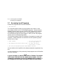
Accessing Local Programs . . . . . . . . . . . . . . . . . . .
3.1.1
Error Message after Executing SET HOST/DUP
3.2
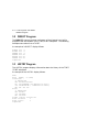
DIRECT Program . . . . . . . . . . . . . . . . . . . . . . . . . .
3.3
HISTRY Program . . . . . . . . . . . . . . . . . . . . . . . . . .
3.4
PARAMS Utility . . . . . . . . . . . . . . . . . . . . . . . . . . .
3.4.1
Selecting Density with the TF867 . . . . . . . . . . .
3.4.2
Displaying, Setting, and Saving Parameters . . .
3.4.2.1
SHOW command . . . . . . . . . . . . . . . . . . . . . .
3.4.2.2
SET Command . . . . . . . . . . . . . . . . . . . . . . . .
3.4.2.3
WRITE Command . . . . . . . . . . . . . . . . . . . . .
3.4.2.4
STATUS Command . . . . . . . . . . . . . . . . . . . .
3.4.2.5
HELP Command . . . . . . . . . . . . . . . . . . . . . .
3.4.2.6
EXIT Command . . . . . . . . . . . . . . . . . . . . . . .
3.5
DRVEXR Progam . . . . . . . . . . . . . . . . . . . . . . . . . .
3.6
DRVTST Program . . . . . . . . . . . . . . . . . . . . . . . . .
3.7
LDRTST Program . . . . . . . . . . . . . . . . . . . . . . . . .
.
.
.
.
.
.
.
.
.
.
.
.
.
.
.
.
.
.
.
.
.
.
.
.
.
.
.
.
.
.
.
.
.
.
.
.
.
.
.
.
.
.
.
.
.
.
.
.
.
.
.
.
.
.
.
.
.
.
.
.
.
.
.
.
.
.
.
.
.
.
.
.
.
.
.
.
.
.
.
.
.
.
.
.
.
.
.
.
.
.
.
.
.
.
.
.
.
.
.
.
.
.
.
.
.
.
.
.
.
.
.
.
.
.
.
.
.
.
.
.
.
.
.
.
.
.
.
.
3–2
3–3
3–4
3–4
3–5
3–5
3–6
3–6
3–7
3–7
3–7
3–7
3–8
3–8
3–9
3–9
3
Local Programs and Utilities
Contents v
4
Troubleshooting Procedures
4.1
Avoiding Basic Problems . . . . . . . . . . . .
4.2
Backup Operation Failure . . . . . . . . . . .
4.3
Nondetectable FRU Failure . . . . . . . . . .
4.4
Error Conditions . . . . . . . . . . . . . . . . . .
4.4.1
Detecting Common Failure Influences
4.4.2
Soft Errors . . . . . . . . . . . . . . . . . . . . .
4.4.3
Common Failures . . . . . . . . . . . . . . . .
4.5
Magazine and Loader Faults . . . . . . . . .
4.5.1
Magazine Fault Description . . . . . . . .
4.5.1.1
Clearing a Magazine Fault . . . . . . .
4.5.2
Loader Fault Description . . . . . . . . . .
4.5.2.1
Clearing a Loader Fault . . . . . . . . .
4.6
Power Problems . . . . . . . . . . . . . . . . . . .
4.7
Cartridge Motion Faults . . . . . . . . . . . .
4.7.1
Isolating Cartridge Motion Faults . . .
4.7.2
Recovering Cartridges . . . . . . . . . . . .
.
.
.
.
.
.
.
.
.
.
.
.
.
.
.
.
.
.
.
.
.
.
.
.
.
.
.
.
.
.
.
.
.
.
.
.
.
.
.
.
.
.
.
.
.
.
.
.
.
.
.
.
.
.
.
.
.
.
.
.
.
.
.
.
. 4–1
. 4–2
. 4–3
. 4–4
. 4–4
. 4–4
. 4–5
. 4–6
. 4–6
. 4–8
. 4–8
. 4–8
. 4–9
. 4–9
. 4–9
. 4–12
Recommended Spares and Service Aids . . . . . . . . . . . . .
Removal and Replacement Guidelines . . . . . . . . . . . . . .
Manually Opening the Receiver . . . . . . . . . . . . . . . . . . .
Removing and Replacing the Controller Module . . . . . .
Beginning the Warm Swap Procedure . . . . . . . . . . . .
Collecting and Recording Original Controller Module
Parameters . . . . . . . . . . . . . . . . . . . . . . . . . . . . . . . .
5.4.2.1
Using the ANALYZE/SYSTEM Command . . . . . . .
5.4.2.2
Using the SET HOST/DUP Command . . . . . . . . . .
5.4.3
Swapping the Controller Module . . . . . . . . . . . . . . . .
5.4.4
Restoring Parameters . . . . . . . . . . . . . . . . . . . . . . . .
5.4.5
Completing the Warm Swap Procedure . . . . . . . . . . .
5.5
Removing and Replacing the Loader Transfer Assembly
5.6
Removing and Replacing the TK85/TZ86 Tape Drive . . .
5.7
Removing and Replacing the TK/TZ Takeup Leader . . .
5.8
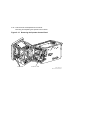
Removing and Replacing the Operator Control Panel . .
5.9
Removing and Replacing the Fan . . . . . . . . . . . . . . . . . .
.
.
.
.
.
.
.
.
.
.
.
.
.
.
.
. 5–3
. 5–6
. 5–7
. 5–9
. 5–10
.
.
.
.
.
.
.
.
.
.
.
.
.
.
.
.
.
.
.
.
.
.
.
.
.
.
.
.
.
.
.
.
.
.
.
.
.
.
.
.
.
.
.
.
5
.
.
.
.
.
.
.
.
.
.
.
.
.
.
.
.
.
.
.
.
.
.
.
.
.
.
.
.
.
.
.
.
.
.
.
.
.
.
.
.
.
.
.
.
.
.
.
.
.
.
.
.
.
.
.
.
.
.
.
.
.
.
.
.
.
.
.
.
.
.
.
.
.
.
.
.
.
.
.
.
.
.
.
.
.
.
.
.
.
.
.
.
.
.
.
.
.
.
.
.
.
.
.
.
.
.
.
.
.
.
.
.
.
.
.
.
.
.
.
.
.
.
.
.
.
.
.
.
.
.
.
.
.
.
.
.
.
.
.
.
.
.
.
.
.
.
.
.
.
.
.
.
.
.
.
.
.
.
.
.
.
.
.
.
.
.
.
.
.
.
.
.
.
.
.
.
FRU Removal and Replacement Procedures
5.1
5.2
5.3
5.4
5.4.1
5.4.2
5–10
5–11
5–12
5–13
5–19
5–20
5–21
5–25
5–32
5–35
5–37
vi Contents
5.10
5.11
5.12
5.13
6
Removing
Only) . . .
Removing
Removing
Removing
and Replacing the Interlock Switch (Older Models
........................................
and Replacing the Power Supply Assembly . . . . . .
and Replacing the Handle Motor Assembly . . . . . .
and Replacing the Mode Select Keylock . . . . . . . . .
5–38
5–40
5–42
5–44
TF85/TF86 Diagnostic Utilities and Tests
6.1
TF85/TF86 POST Procedure . . . . . .
6.1.1
Burn-in Loopback Mode . . . . . . . .
6.1.2
POST Terminal Server . . . . . . . . .
6.1.3
Lastfail Information . . . . . . . . . . .
6.1.4
Break Operation . . . . . . . . . . . . .
6.2
Functional Microdiagnostic Tests . . .
6.2.1
Microdiagnostic Test Functions . .
6.2.2
Product Users and Uses . . . . . . . .
6.3
Microdiagnostic Test Descriptions . .
6.3.1
FTST02 - Simple Write/Read Test
6.3.2
FTST03 - Positioning Test . . . . . .
6.3.3
FTST04 - Short Read Test . . . . . .
6.3.4
FTST05 - Streaming Write Test . .
6.3.5
FTST06 - Streaming Read Test . .
6.3.6
FTST07 - Thrashing Write Test . .
6.3.7
FTST08 - Thrashing Read Test . .
6.3.8
FTST09 - Append Test . . . . . . . . .
6.3.9
FTST10 - Overwrite Test . . . . . . .
6.3.10 DRVTST - Drive Test . . . . . . . . . .
6.3.11 DRVEXR - Drive Exerciser . . . . .
6.3.12 STREAM . . . . . . . . . . . . . . . . . . .
6.4
Utilities for Changing Parameters . .
6.4.1
Utility 1 - PARAMS . . . . . . . . . . .
6.4.1.1
WRITE Command . . . . . . . . . .
6.4.1.2
STATUS Command . . . . . . . . .
6.4.2
Utility 2 - HISTRY . . . . . . . . . . . .
6.4.3
Utility 3 - DIRECT . . . . . . . . . . . .
6.5
Loader Procedures . . . . . . . . . . . . . .
.
.
.
.
.
.
.
.
.
.
.
.
.
.
.
.
.
.
.
.
.
.
.
.
.
.
.
.
.
.
.
.
.
.
.
.
.
.
.
.
.
.
.
.
.
.
.
.
.
.
.
.
.
.
.
.
.
.
.
.
.
.
.
.
.
.
.
.
.
.
.
.
.
.
.
.
.
.
.
.
.
.
.
.
.
.
.
.
.
.
.
.
.
.
.
.
.
.
.
.
.
.
.
.
.
.
.
.
.
.
.
.
.
.
.
.
.
.
.
.
.
.
.
.
.
.
.
.
.
.
.
.
.
.
.
.
.
.
.
.
.
.
.
.
.
.
.
.
.
.
.
.
.
.
.
.
.
.
.
.
.
.
.
.
.
.
.
.
.
.
.
.
.
.
.
.
.
.
.
.
.
.
.
.
.
.
.
.
.
.
.
.
.
.
.
.
.
.
.
.
.
.
.
.
.
.
.
.
.
.
.
.
.
.
.
.
.
.
.
.
.
.
.
.
.
.
.
.
.
.
.
.
.
.
.
.
.
.
.
.
.
.
.
.
.
.
.
.
.
.
.
.
.
.
.
.
.
.
.
.
.
.
.
.
.
.
.
.
.
.
.
.
.
.
.
.
.
.
.
.
.
.
.
.
.
.
.
.
.
.
.
.
.
.
.
.
.
.
.
.
.
.
.
.
.
.
.
.
.
.
.
.
.
.
.
.
.
.
.
.
.
.
.
.
.
.
.
.
.
.
.
.
.
.
.
.
.
.
.
.
.
.
.
.
.
.
.
.
.
.
.
.
.
.
.
.
.
.
.
.
.
.
.
.
.
.
.
.
.
.
.
.
.
.
.
.
.
.
.
.
.
.
.
.
.
.
.
.
.
.
.
.
.
.
.
.
.
.
.
.
.
.
.
.
.
.
.
.
.
.
.
.
.
.
.
.
.
.
.
.
.
.
.
.
.
.
.
.
.
.
.
.
.
.
.
.
.
.
.
.
.
.
.
.
.
.
.
.
.
.
.
.
.
.
.
.
.
.
.
.
.
.
.
.
.
.
.
.
.
.
.
.
.
.
.
.
.
.
.
.
.
.
.
.
.
.
.
.
.
.
.
.
.
.
.
.
.
.
.
.
.
.
.
.
.
.
.
.
.
.
.
.
.
.
.
.
.
.
.
.
.
.
.
.
.
.
.
.
.
.
.
.
6–1
6–1
6–2
6–2
6–2
6–3
6–3
6–3
6–4
6–4
6–4
6–4
6–5
6–5
6–5
6–6
6–6
6–6
6–6
6–7
6–7
6–7
6–7
6–7
6–7
6–8
6–8
6–8
Contents vii
6.5.1
LDRTST - Loader Exerciser . . . . . . . . . . . . . . .
6.5.1.1
LTST01 - Loader Loopback Test . . . . . . . . . .
6.5.1.2
LTST02 - Loader Illegal Command Test . . . .
6.5.1.3
LTST03 - Loader Internal Self-Test . . . . . . .
6.5.1.4
LTST04 - Loader Movement Test . . . . . . . . .
6.5.2
LTST05 - Cartridge Access Test . . . . . . . . . . . .
6.5.3
LTST06 - Loader Commands Test . . . . . . . . . .
6.5.4
LTST07 - Change Test Parameters . . . . . . . . .
6.5.5
LTST08 - Change Loader Cycle Count . . . . . . .
6.5.6
LTST09 - Loader Streaming Write/Read Test . .
6.5.7
LTST10 - Loader Thrashing Write/Read Test . .
6.5.8
LTST11 - Loader Streaming Read Test . . . . . .
6.5.9
HCART0 — HCART6 - Load Cartridge Utility
6.5.10 HSTATS - Loader Status Utility . . . . . . . . . . .
6.5.11 Failure Action . . . . . . . . . . . . . . . . . . . . . . . . .
6.6
Host Level Diagnostics . . . . . . . . . . . . . . . . . . . . .
6.6.1
System Verification Test . . . . . . . . . . . . . . . . .
6.6.2
Diagnostic Supervisor . . . . . . . . . . . . . . . . . . .
7
.
.
.
.
.
.
.
.
.
.
.
.
.
.
.
.
.
.
.
.
.
.
.
.
.
.
.
.
.
.
.
.
.
.
.
.
.......
.......
.......
.......
.......
.......
.......
.......
.......
.......
.......
.......
.......
.......
.......
.......
.......
.......
.
.
.
.
.
.
.
.
.
.
.
.
.
.
.
.
.
.
.
.
.
.
.
.
.
.
.
.
.
.
.
.
.
.
.
.
.
.
.
.
.
.
.
.
.
.
.
.
6–8
6–9
6–9
6–9
6–9
6–9
6–10
6–10
6–10
6–10
6–10
6–10
6–10
6–10
6–11
6–11
6–11
6–11
TZ85/TZ86 Diagnostic Utilities and Tests
7.1
POST . . . . . . . . . . . . . . . . . . . . . .
7.1.1
Burn-in Loopback Mode . . . . . .
7.1.2
SCSI Bus Termination . . . . . . .
7.1.3
POST Terminal Server . . . . . . .
7.1.4
Lastfail Information . . . . . . . . .
7.2
Break Key Operation . . . . . . . . . .
7.3
Test Descriptions . . . . . . . . . . . . .
7.3.1
Diagnostic Server . . . . . . . . . . .
7.3.2
Diagnostic Terminal Server . . .
7.3.2.1
Data Patterns . . . . . . . . . . .
7.3.3
FTST03 - Positioning Test . . . .
7.3.4
FTST05 - Streaming Write Test
7.3.5
FTST06 - Streaming Read Test
7.3.6
FTST13 - Write/Read Test . . . .
7.3.7
STREAM Test . . . . . . . . . . . . .
7.4
SCSI Level Tests . . . . . . . . . . . . .
.
.
.
.
.
.
.
.
.
.
.
.
.
.
.
.
.
.
.
.
.
.
.
.
.
.
.
.
.
.
.
.
.
.
.
.
.
.
.
.
.
.
.
.
.
.
.
.
.
.
.
.
.
.
.
.
.
.
.
.
.
.
.
.
.
.
.
.
.
.
.
.
.
.
.
.
.
.
.
.
.
.
.
.
.
.
.
.
.
.
.
.
.
.
.
.
.
.
.
.
.
.
.
.
.
.
.
.
.
.
.
.
.
.
.
.
.
.
.
.
.
.
.
.
.
.
.
.
.
.
.
.
.
.
.
.
.
.
.
.
.
.
.
.
.
.
.
.
.
.
.
.
.
.
.
.
.
.
.
.
.
.
.
.
.
.
.
.
.
.
.
.
.
.
.
.
.
.
.
.
.
.
.
.
.
.
.
.
.
.
.
.
.
.
.
.
.
.
.
.
.
.
.
.
.
.
.
.
.
.
.
.
.
.
.
.
.
.
.
.
.
.
.
.
.
.
.
.
.
.
.
.
.
.
.
.
.
.
.
.
.
.
.
.
.
.
.
.
.
.
.
.
.
.
.
.
.
.
.
.
.
.
.
.
.
.
.
.
.
.
.
.
.
.
.
.
.
.
.
.
.
.
.
.
.
.
.
.
7–1
7–1
7–1
7–2
7–2
7–3
7–3
7–3
7–3
7–4
7–4
7–5
7–5
7–5
7–6
7–6
viii Contents
7.4.1
7.4.2
7.4.3
7.4.4
7.4.5
8
TEST01 - SCSI Level 1 Test . . . . . . . . . . . . . .
TEST02 - SCSI Level 2 Test . . . . . . . . . . . . . .
LTST09 - Loader Streaming Write/Read Test .
LTST11 - Loader Read All Test . . . . . . . . . . .
Retry Algorithm . . . . . . . . . . . . . . . . . . . . . . .
.
.
.
.
.
.
.
.
.
.
.
.
.
.
.
.
.
.
.
.
.
.
.
.
.
.
.
.
.
.
.
.
.
.
.
.
.
.
.
.
.
.
.
.
.
.
.
.
.
.
7–6
7–6
7–6
7–6
7–7
.
.
.
.
.
.
.
.
.
.
.
.
.
.
.
.
.
.
.
.
.
.
.
.
.
.
.
.
.
.
.
.
.
.
.
.
.
.
.
.
.
.
.
.
.
.
.
.
.
.
.
.
.
.
.
.
.
.
.
.
.
.
.
.
.
.
.
.
.
.
.
.
.
.
.
.
.
.
.
.
.
.
.
.
.
.
.
.
.
.
.
.
.
.
.
.
.
.
.
.
.
.
.
.
.
.
.
.
.
.
8–1
8–1
8–2
8–3
8–5
8–9
8–10
8–10
8–11
8–12
8–13
.
.
.
.
.
.
.
.
.
.
.
.
.
.
.
.
.
.
.
.
.
.
.
.
.
.
.
.
.
.
.
.
.
.
.
.
.
.
.
.
.
.
.
.
.
.
.
.
.
.
.
.
.
.
.
.
.
.
.
.
.
.
.
.
.
.
.
.
.
.
.
.
.
.
.
.
.
.
.
.
.
.
.
.
.
.
.
.
.
.
.
.
.
.
.
.
.
.
.
. A–2
. A–2
. A–3
. A–3
. A–4
. A–4
. A–4
. A–6
. A–9
. A–10
. A–11
Firmware Update Procedures
8.1
TF85x Subsystem Firmware Update Procedure .
8.1.1
Running the VMSINSTAL Procedure . . . . . . .
8.1.2
Beginning the TF85x Firmware Update . . . . .
8.1.2.1
TF857 Subsystem Firmware Update Mode
8.1.2.2
TF85 Firmware Update Mode . . . . . . . . . .
8.2
TZ85x Subsystem Firmware Update Procedure
8.2.1
Installing TZ85x Subsystem Firmware . . . . .
8.2.1.1
TZ85 (Drive-Only) Configuration Update . .
8.2.1.2
TZ857 Loader Configuration Update . . . . .
8.2.2
Installing Firmware into a Standalone Drive .
8.2.3
Firmware Update Results . . . . . . . . . . . . . . .
A
A.1
A.1.1
A.1.2
A.1.3
A.1.4
A.1.5
A.2
A.3
A.4
A.5
A.6
EVMDA Tape Drive Exerciser Tests
EVMDA Tests . . . . . . . . . . . . . .
Test 1 — Acceptance Test . . . .
Test 2 — Qualification Test . .
Test 3 — Multi Unit Test . . . .
Test 4 — Read Unknown Tape
Test 5 — Conversation Mode .
Invoking EVMDA . . . . . . . . . . . .
User Dialogue . . . . . . . . . . . . . .
Error Messages . . . . . . . . . . . . .
Event Flags . . . . . . . . . . . . . . . .
Statistics . . . . . . . . . . . . . . . . . .
.
.
.
.
.
.
.
.
.
.
.
.
.
.
.
.
.
.
.
.
.
.
.
.
.
.
.
.
.
.
.
.
.
.
.
.
.
.
.
.
.
.
.
.
.
.
.
.
.
.
.
.
.
.
.
.
.
.
.
.
.
.
.
.
.
.
.
.
.
.
.
.
.
.
.
.
.
.
.
.
.
.
.
.
.
.
.
.
.
.
.
.
.
.
.
.
.
.
.
.
.
.
.
.
.
.
.
.
.
.
.
.
.
.
.
.
.
.
.
.
.
.
.
.
.
.
.
.
.
.
.
.
Contents ix
B
Head Cleaning Procedure
B.1 Accessing the Drive . . . . . . . . . . . . . . . . . . . . . . . . . . . . . . .
B.1.1
Loading the CleaningTape III Cartridge into the Drive . .
B.1.2
Securing the Tx800 Magazine Tape Subsystem . . . . . . . .
B.2 Inserting the CleaningTape III Cartridge into the Magazine
C
C.1
C.2
C.3
D
. B–6
. B–9
. B–9
. B–11
Error Logs
Media Loader Errors . . . . . . . . . . . . . . . . . . . . . . . . . . . . . . .
TF857 Subsystem Error Codes . . . . . . . . . . . . . . . . . . . . . . . .
TF857 Subsystem Command Codes . . . . . . . . . . . . . . . . . . . .
C–2
C–5
C–8
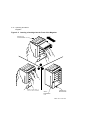
TF/TZ 85/86 Removal and Replacement Procedure
D.1 Preliminary Steps . . . . . . . . . . . . . . . . . . . .
D.1.1
Removing the Enclosure Top . . . . . . . . . .
D.1.2
Removing the Fan . . . . . . . . . . . . . . . . . .
D.1.3
Removing the SCSI ID Switch and Cable
D.1.4
Removing the Internal SCSI Bus Cable . .
D.1.5
Removing the Controller Module . . . . . . .
D.1.6
Removing the Power Supply . . . . . . . . . .
D.1.7
Removing the Drive . . . . . . . . . . . . . . . . .
.
.
.
.
.
.
.
.
.
.
.
.
.
.
.
.
.
.
.
.
.
.
.
.
.
.
.
.
.
.
.
.
.
.
.
.
.
.
.
.
.
.
.
.
.
.
.
.
.
.
.
.
.
.
.
.
.
.
.
.
.
.
.
.
.
.
.
.
.
.
.
.
.
.
.
.
.
.
.
.
.
.
.
.
.
.
.
.
.
.
.
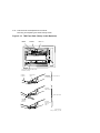
.
.
.
.
.
.
.
.
.
.
.
.
.
D–1
D–1
D–1
D–2
D–2
D–2
D–2
D–3
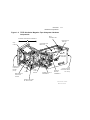
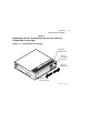
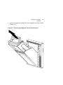
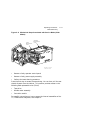
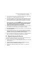
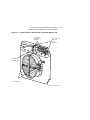
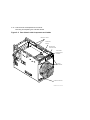
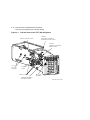
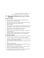
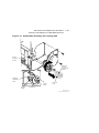
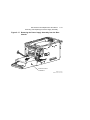
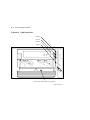
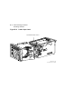
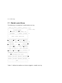
Front View of the TF/TZ 800-Series Operator Control Panel
TF/TZ 800-Series Magazine Tape Subsystem Hardware
Components . . . . . . . . . . . . . . . . . . . . . . . . . . . . . . . . . . . . .
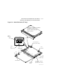
Front View of the TF/TZ 800-Series Magazine . . . . . . . . . . .
CompacTape III Cartridge . . . . . . . . . . . . . . . . . . . . . . . . . .
TF/TZ 800-series Operator Control Panel . . . . . . . . . . . . . .
Front View of the TF/TZ 800-series Magazine . . . . . . . . . . .
Removing the Magazine from the Open Receiver . . . . . . . . .
Write-Protect Switch on the CompacTape III . . . . . . . . . . . .
Inserting a Cartridge into the Front of the Magazine . . . . .
.
1–3
Index
Figures
1–1
1–2
1–3
1–4
2–1
2–2
2–3
2–4
2–5
. 1–5
. 1–6
. 1–9
. 2–4
. 2–7
. 2–9
. 2–11
. 2–12
x Contents
2–6
2–7
2–8
2–9
4–1
4–2
4–3
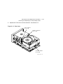
5–1
5–2
5–3
5–4
5–5
5–6
5–7
5–8
5–9
5–10
5–11
5–12
5–13
5–14
5–15
5–16
5–17
5–18
8–1
8–2
B–1
B–2
B–3
B–4
B–5
B–6
Removing a Cartridge from the Front of the Magazine . . . . .
Mechanical Stops Associated with Service Mode (Newer
Models) . . . . . . . . . . . . . . . . . . . . . . . . . . . . . . . . . . . . . . . . .
Mechanical Stops Associated with Service Mode (Older
Modes) . . . . . . . . . . . . . . . . . . . . . . . . . . . . . . . . . . . . . . . . . .
TK85 Front Panel . . . . . . . . . . . . . . . . . . . . . . . . . . . . . . . . .
Opening the Cartridge Door to Check the Tape Leader . . . . .
Loader Open Latch . . . . . . . . . . . . . . . . . . . . . . . . . . . . . . . .
Mechanical Ejection Lever . . . . . . . . . . . . . . . . . . . . . . . . . . .
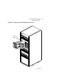
TF/TZ 800 Magazine Tape Subsystem FRUs . . . . . . . . . . . . .
First Mechanical Stop . . . . . . . . . . . . . . . . . . . . . . . . . . . . . .
Manually Opening the Receiver . . . . . . . . . . . . . . . . . . . . . . .
Captive Screws Securing the Controller Module Tray . . . . . .
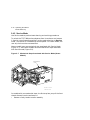
Rear Chassis with Components and Cables . . . . . . . . . . . . . .
Node ID Switches (TF Only) . . . . . . . . . . . . . . . . . . . . . . . . .
Left Side View of the TF/TZ 800 Subsystem . . . . . . . . . . . . .
Loader Transfer Assembly Latch Position . . . . . . . . . . . . . . .
Front of the Magazine Showing Cartridge Slot Numbers . . . .
Second Mechanical Stop . . . . . . . . . . . . . . . . . . . . . . . . . . . . .
TF/TZ 800 Subsystem Cables and Components . . . . . . . . . . .
Handle Motor Assembly and Coupling Shaft . . . . . . . . . . . . .
Dust Cover . . . . . . . . . . . . . . . . . . . . . . . . . . . . . . . . . . . . . . .
TK85 Tape Path (Takeup Leader Replaced) . . . . . . . . . . . . . .
Removing the Operator Control Panel . . . . . . . . . . . . . . . . . .
Interlock Switch . . . . . . . . . . . . . . . . . . . . . . . . . . . . . . . . . . .
Removing the Power Supply Assembly from the Rear Chassis
Key Lock Assembly . . . . . . . . . . . . . . . . . . . . . . . . . . . . . . . .
Front View of the TF/TZ 85x-series Operator Control Panel .
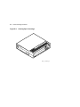
Tape Drive Controls and Indicators . . . . . . . . . . . . . . . . . . . .
CleaningTape III Cartridge . . . . . . . . . . . . . . . . . . . . . . . . . .
TK85 Front Panel . . . . . . . . . . . . . . . . . . . . . . . . . . . . . . . . .
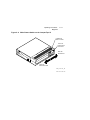
Tx800 Operator Control Panel . . . . . . . . . . . . . . . . . . . . . . . .
Sliding the Tx800 Subsystem Toward You . . . . . . . . . . . . . . .
Loader Open Latch . . . . . . . . . . . . . . . . . . . . . . . . . . . . . . . .
Loading the Cartridge . . . . . . . . . . . . . . . . . . . . . . . . . . . . . .
2–14
2–16
2–17
2–20
4–2
4–10
4–11
5–5
5–8
5–9
5–15
5–16
5–17
5–18
5–22
5–24
5–26
5–27
5–29
5–33
5–34
5–36
5–39
5–41
5–45
8–4
8–6
B–2
B–4
B–5
B–7
B–8
B–10
Contents xi
Tables
1
1–1
1–2
1–3
1–4
2–1
3–1
4–1
4–2
5–1
5–2
5–3
7–1
A–1
C–1
C–2
C–3
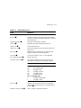
Related Documents . . . . . . . . . . . . . . . . . . . . . . . . . . . . . . .
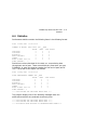
Read/Write Cartridge Compatibility . . . . . . . . . . . . . . . . . .
TF/TZ 800-series Magazine Tape Subsystem Diagnostics . . .
TF/TZ 800-series Magazine Tape Subsystem Specifications .
TK85/TK86 Tape Drive Specifications . . . . . . . . . . . . . . . . .
TF/TZ 800-series OCP Pushbutton and Indicator Functions
Summary of TF857/TF867 Subsystem Parameters . . . . . . .
Nondetectable FRU Failures . . . . . . . . . . . . . . . . . . . . . . . .
Common Failures, Causes, and Corrections . . . . . . . . . . . . .
Field Replaceable Units and Related Procedures . . . . . . . . .
Recommended Spares List . . . . . . . . . . . . . . . . . . . . . . . . . .
Service Aids . . . . . . . . . . . . . . . . . . . . . . . . . . . . . . . . . . . . .
Program Data Patterns . . . . . . . . . . . . . . . . . . . . . . . . . . . .
Data Patterns . . . . . . . . . . . . . . . . . . . . . . . . . . . . . . . . . . .
TF857 Media Errors . . . . . . . . . . . . . . . . . . . . . . . . . . . . . . .
Error Codes . . . . . . . . . . . . . . . . . . . . . . . . . . . . . . . . . . . . .
Command Codes . . . . . . . . . . . . . . . . . . . . . . . . . . . . . . . . .
.
xiv
. 1–8
. 1–10
. 1–11
. 1–12
. 2–1
. 3–5
. 4–3
. 4–5
. 5–2
. 5–3
. 5–6
. 7–4
. A–8
. C–3
. C–5
. C–8
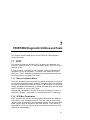
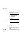
Preface
This manual describes how to service the following tape subsystems:
•
TF857/TF867 DSSI magazine
•
TZ857/TZ867 SCSI magazine
•
TF85/TF86 DSSI tabletop cartridge
•
TZ85/TZ86 SCSI tabletop cartridge
Manual Structure
Chapter 1, Overview, provides a basic product description of the hardware
components and specifications of the TF/TZ 800-series magazine tape
subsystems.
Chapter 2, Operating Procedures , describes the operating features of
the operator control panel (OCP) buttons and indicators, the magazine
and cartridge removal and replacement processes, and the mode select
key operating modes. Chapter 2 also describes the TF/TZ 800 subsystem
initialization process and loader transfer assembly, TK85 tape drive, and
controller module activities during power-on self-test (POST).
Chapter 3, Local Programs and Utilities, describes troubleshooting
procedures using local diagnostic programs and utilities and the SET
HOST/DUP command.
Chapter 4, Troubleshooting Procedures, describes error conditions in
the TF/TZ 800 subsystem, magazine and loader faults, cartridge motion
faults, and problem resolutions.
Chapter 5, FRU Removal and Replacement Procedures, describes the TF
/TZ 800 subsystem FRU removal and replacement procedures. Included is
a warm swap procedure for replacing the controller module.
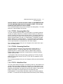
Chapter 6, TF85/TF86 Diagnostic Utilities and Tests, describes the TF85
POST procedure, functional microdiagnostic test, and test descriptions.
Chapter 7, TZ85/TZ86 Diagnostic Utilities and Tests, describes
compatibility restrictions and requirements, installation, firmware update
procedures, and more.
Chapter 8, Firmware Update Procedures, describes the firmware update
procedures for both TF and TZ-series of products.
xiii
xiv Preface
Manual Structure
Appendix A, EVMDA Tape Drive Exerciser Tests, describes how to run
the EVMDA test under the VAX Diagnostic Supervisor (VDS).
Appendix B, Head Cleaning Procedure, describes how to use the
CleaningTape III cartridge to clean the read/write head.
Appendix C, Error Logs, lists the device-dependent error and status codes,
and the error reporting format.
Appendix D, TF/TZ 85/86 Removal and Replacement Procedure , describes
the TF/TZ 85/86 removal and replacement procedure.
An index is included in this service guide.
Intended Audience
This manual is for use by Digital Services engineers.
Conventions
The terms TF/TZ 800 or TF85x and TZ85x refer to the TF/TZ 800series of magazine tape subsystems; in particular, the TF857 and TZ857
magazine tape subsystems.
The Eject, Load/Unload, and Slot Select buttons on the TF857 operator
control panel (OCP) are referred to as the OCP pushbuttons.
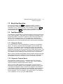
Related Documentation
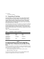
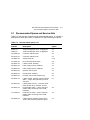
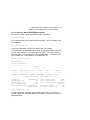
Table 1 lists references that supplement this manual.
Table 1 Related Documents
Title
Audience
Order Number
TF/TZ 800 Magazine Tape
Subsystem Owner’s Manual
Customers
EK–TF857–OM
SF200 Storage Array
Installation Guide
Digital Customer
Services personnel
EK–SF200–IG
KFMSA Module Installation
and User Manual
Digital Customer
Services personnel
EK–KFMSA–IM
VAX/VMS Backup Utility
Reference Manual
System managers and
operators
AA–Z407B–TE
Preface
Related Documentation
xv
Table 1 (Continued) Related Documents
Title
Audience
Order Number
Guide to VAX/VMS Disk and
Magnetic Tape Operations
System managers and
operators
AI–Y506B–TE
VAX/VMS Mount Utility
Reference Manual
System managers and
operators
AA–Z424A–TE
VMS System Manager’s
Manual
System managers
AA–LA00B–TE
TK85 Tape Drive Operator’s
Reference Card
Customers
EK–OTK85–RC
1
Overview
1.1 Overview
The TF/TZ 800-series magazine tape subsystems are electromechanical
devices that can store approximatly 18.2 gigabytes of data on a TZ857
and 42 gigabytes on a TZ867. Using CompacTape III cartridges, these
subsystems can store up to 2.6 gigabytes of data per cartridge on the
TZ85, and 6.0 gigabytes of data per cartridge on the TZ86.
The TF/TZ 800-series magazine tape subsystems can load and unload tape
cartridges into and from a tape drive, providing a degree of unattended
backup, as well as perform single cartridge operations. The TF/TZ 800series subsystems perform automatic, sequential tape operations.
In addition, these subsystems execute operating system commands,
qualifiers, and parameters to store data from user disk areas to the
tape drive.
1.2 Operating Modes
The TF/TZ 800-series subsystems operate in the following modes:
•
OCP Disabled mode — Locks the subsystem into the enclosure
and locks the receiver. The pushbuttons on the operator control panel
(OCP) are disabled. This mode automatically loads the next tape
cartridge into the drive after you issue the DISMOUNT command.
•
Automatic mode — Is the subsystem’s default, or normal, mode.
It locks the subsystem into the enclosure but leaves the receiver
unlocked. This mode automatically loads the next tape cartridge
into the drive after you issue the DISMOUNT command. The OCP
pushbuttons are enabled.
1–1
1–2 Overview
Operating Modes
•
Manual mode — Locks the subsystem into the enclosure but
leaves the receiver unlocked. This mode allows for single cartridge
operations only. The OCP pushbuttons are enabled. Loading and
unloading of one cartridge to the next is not automatic; operator
intervention is required to select the next, or any other, cartridge.
•
Service mode — Unlocks the subsystem from the enclosure and
removes it from its normal operating position. Use this mode when
performing the head cleaning, jam recovery, and servicing procedures.
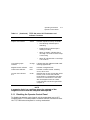
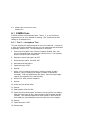
You can select these modes through the Mode Select key (Figure 1–1). See
Section 2.4 for more information.
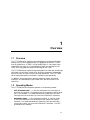
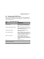
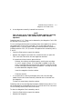
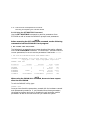
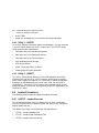
1.3
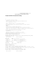
Node ID Label
The operator control panel on the TF857 subsystem has a space for a
DSSI node ID label that identifies the device bus ID number (Figure 1–1).
The DSSI node ID number is preset during manufacturing to its normal
setting of zero (0) and should be verified during installation at the
customer site. You may want to place a label noting the device SCSI
ID number in this space.
Overview
Node ID Label
1–3
Figure 1–1 Front View of the TF/TZ 800-Series Operator Control Panel
O PERAT O R CO NT RO L PANEL
Eject
Load/Unload
MOD E S E LE C T K E Y
BUTTON
AND
INDICATOR
AREA
Slot Select
OCP
DISABLED
0
AUTOMATIC
MODE
Power On
OCP LABEL
CURRENT
SLOT
INDICATORS
0-6
Write
Protected
Tape In Use
1
MANUAL
MODE
Use
Cleaning Tape
SERVICE
MODE
Magazine
Fault
Loader Fault
2
Eject
3
DSSI NODE
ID LABEL
(TF857 ONLY)
Load/Unload
Slot Select
0
Power On
Write
Protected
Write Protect
Load Fault
1
Tape In Use
Use
Cleaning Tape
4
Magazine
Fault
Loader Fault
2
3
5
4
5
6
6
40% REDUCTION
SHR_X1025E_91
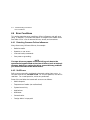
1–4 Overview
Hardware Components
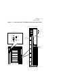
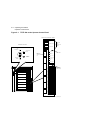
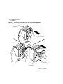
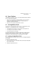
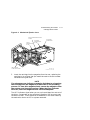
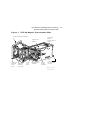
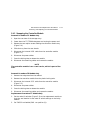
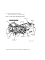
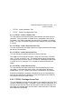
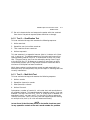
1.4 Hardware Components
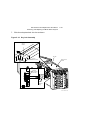
The TF/TZ 800-series magazine tape subsystem consists of the following
major hardware components (Figure 1–2):
•
Loader Transfer Assembly
— Operator control panel (OCP)
— Magazine
•
Rear Chassis
— TK85 tape drive
— Power supply assembly
— Handle motor assembly
— Fan
— Interlock switch
— Controller module
1.4.1 Loader Transfer Assembly
The loader transfer assembly contains an elevator that moves to each of
the storage slots in the magazine, as well as to the cartridge opening in
the tape drive. This mechanism inserts and extracts the tape cartridges
into and from the magazine and drive. (The signals that drive the
elevator mechanics originate at the loader transfer assembly electronics
module.)
1.4.1.1 Operator Control Panel
The TF/TZ 800-Series operator control panel contains three OCP
pushbuttons—Eject, Load/Unload, and Slot Select—as well as indicators
that are used with the Mode Select key and tape drive status
(Section 2.4).
Overview
Hardware Components
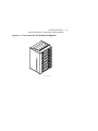
1–5
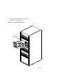
Figure 1–2 TF/TZ 800-Series Magazine Tape Subsystem Hardware
Components
BUS
CONNECTOR
LOADER TRANSFER ASSEMBLY
INTERLOCK
SWITCH
OCP
CABLE
CONTROLLER
MODULE
RIGHT
CAPTIVE
SCREWS
OPERATOR
CONTROL
PANEL
(OCP)
LATCH
TK85
TAPE
DRIVE
MECHANICAL
EJECTION
LEVER
POWER SUPPLY
ASSEMBLY
HANDLE
MOTOR
ASSEMBLY
FAN
(LOCATED ON
OUTSIDE REAR
OF UNIT)
HOME POSITION
OF ELEVATOR
SHR-X0147H-92-CPG
ZKO-1285-01-DG
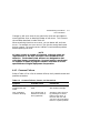
1–6 Overview
Hardware Components
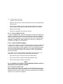
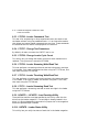
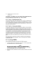
1.4.1.2 Magazine
The TF/TZ 800-Series subsystem’s magazine (Figure 1–3) serves as
a removable cartridge container. The magazine stores up to seven
CompacTape III cartridges.
Figure 1–3 Front View of the TF/TZ 800-Series Magazine
0
1
2
3
4
5
6
SHR_X1023A_89
Overview
Hardware Components
1–7
1.4.2 Rear Chassis
The rear chassis contains the TK85 tape drive, power supply assembly,
handle motor assembly, fan, interlock switch, and controller module.
1.4.2.1 TK85/TK86 Tape Drive
The tape drive is a streaming tape drive that stores up to 2.6 gigabytes
for the TK85 and 6.0 gigabytes for the TK86 of data on each of its tape
cartridges. The TK85 and TK86 drives receive commands from the
controller module that connects the TF/TZ 800-series subsystem to the
host system.
1.4.2.2 Power Supply Assembly
The power supply assembly provides power to the rear chassis components
and to the loader transfer assembly.
1.4.2.3 Handle Motor Assembly
The handle motor assembly lifts and lowers the drive’s handle when
cartridges are ready for insertion into, or removal from, the tape drive.
1.4.2.4 Fan
The fan cools the entire TF/TZ 800-series subsystem.
1.4.2.5 Interlock Switch
The interlock switch disables 24 Vdc to the operator control panel and
loader transfer assembly when the subsystem is moved forward from the
storage array. Newer models do not have this interlock switch.
1.4.2.6 Controller Module
The TF/TZ 800-series magazine tape subsystem connects to the host
system through either a DSSI or SCSI bus. The physical interface is a
controller module that resides in the rear chassis of the TF/TZ 800-series
subsystem.
The subsystem uses a serial communications path to pass commands,
messages, data, and error information between the controller module and
the loader transfer assembly. A second serial communications path exists
between the controller module and the TK85 tape drive.
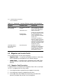
1–8 Overview
CompacTape III Cartridge
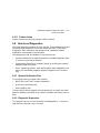
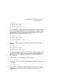
1.5 CompacTape III Cartridge
The CompacTape III cartridge (Figure 1–4) is a gray plastic cartridge
containing 1200 feet of 1/2-inch magnetic, metal particle (MP) tape.
The cartridge has a write-protect switch to prevent accidental erasure
of data. When the switch is moved to the left and the small orange
rectangle is visible, data cannot be written to the tape. A package of
slide-in labels and a cartridge handling information sheet are provided
with each CompacTape III cartridge.
The TK85 tape drive writes 48 tracks (24 pairs) on the tape; the TK86 has
112 tracks (56 pairs) on the tape. It reads and writes data in a two-track
parallel, serpentine fashion, traveling the entire length of tape on two
tracks (at approximately 100 inches per second). The drive then steps the
head and reverses tape direction, and continues to read/write on the next
two tracks.
Table 1–1 shows cartridge compatibility.
Table 1–1 Read/Write Cartridge Compatibility
Cartridge
TK85
TK86
CompacTape
Read
Read
CompacTape
Read
Read
CompacTape III
TK85 Format
Read/Write
Read/Write
CompacTape III
TK86 Format
None
Read/Write
NOTE
For read-only purposes, you can load older CompacTape
cartridges into the TK85 tape drive. Any cartridges recorded
by the TK50, TK70, or TZ30 tape drives can be read by the TK85
drive.
To ensure the reliability of cartridges that contain recorded data and that
may be archived for a long time, store the cartridges in a clean, controlled
environment with the following conditions:
•
Environmental temperature: 18.3°C to 26.1°C (65°F to 79°F)
•
Relative humidity: 20% to 60%
The above environmental conditions are also recommended for shelf
storage of cartridges that do not contain recorded data.
Overview
CompacTape III Cartridge
1–9
NOTE
Degaussing tools for erasing tapes do not work with the
CompacTape III cartridge.
Figure 1–4 CompacTape III Cartridge
ORANGE
INDICATOR
TM
Co
a
mp
cT
a
III
pe
WRITEPROTECT
SWITCH
WRITEENABLED
WRITEPROTECTED
SHR_X1020C_89
1–10 Overview
Service Features
1.6 Service Features
The TF/TZ 800-series magazine tape subsystem has these service features:
•
Power-on self-testing (POST) for the electronics and mechanics
associated with the loader transfer assembly, the tape drive, and
the controller module
•
Automatic calibrating of the tape drive
•
Automatic home positioning of the elevator
•
Mechanical design that allows access to most field replaceable units
(FRUs)
•
Local diagnostic programs for troubleshooting
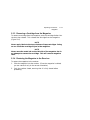
1.7 Diagnostics Listing
Table 1–2 lists the TF/TZ 800-series magazine tape subsystem
diagnostics.
Table 1–2 TF/TZ 800-series Magazine Tape Subsystem Diagnostics
Diagnostic
Component Tested
Reference
POST
Controller module
Chapter 2
POST
Loader transfer assembly
Chapter 2
POST
TK85/TK86 tape drive
Chapter 2
Local
diagnostic
programs
TF/TZ 800-series magazine
tape subsystem
Chapter 4
EVMDA
(under VDS)
TF/TZ 800-series magazine
tape subsystem
Appendix A
Overview
Specifications
1–11
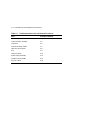
1.8 Specifications
Table 1–3 lists the specifications for the TF/TZ 800-series magazine tape
subsystem, and Table 1–4 lists those for the TK85 and TK86 tape drive.
Table 1–3 TF/TZ 800-series Magazine Tape Subsystem Specifications
Characteristic
Specification(s)
Height
26.47 cm (10.42 in)
Width
22.20 cm (8.74 in)
Length
64.77 cm (25.5 in)
Weight
24.95 kg (55 lb)
Noise level
62 dB
Environmental temperature
Operating
10°C to 40°C (50°F to 104°F)
Nonoperating
–40°C to 66°C (–40°F to 150.8°F)
Humidity
Operating
20% to 80% noncondensing
Nonoperating
10% to 95%
Certification
EMI
Meets applicable FCC, VDE, and FTZ
standards for Class A devices
Safety
Meets UL, CSA, GS mark, VDE, and IEC
standards
Maximum number of cartridges
7
Electrical rating
100 Vac to 120 Vac/220 Vac to 240 Vac
2 amperes/1 ampere
AC power consumption
110 W, typical
113 W, maximum
Communications interface
DSSI/SCSI bus
Cycle time
50 s, maximum
1–12 Overview
Specifications
Table 1–4 TK85/TK86 Tape Drive Specifications
Characteristic
Specification(s)
Mode of operation
Streaming
Media
12.77 mm (1/2 in) unformatted magnetic tape
Track density
96 tracks/in (48 tracks) TK85
Track density
112 tracks/in (56 tracks) TK86
Bit density
42,500 bits/in
Number of tracks
48 TK85
Number of tracks
56 TK86
Maximum transfer
rate (at tape)
800 kilobytes/s
Tape speed
100 in/s
Track format
Two-track parallel, serpentine recording
Cartridge capacity
Up to 2.6 gigabytes, formatted TK85
Cartridge capacity
Up to 6.0 gigabytes, formatted TK86
2
Operating Procedures
This chapter describes the operator control panel (OCP), and the OCP
pushbutton and indicator functions. It describes how to use the magazine
and the mode select key, and the TF/TZ 800-series initialization and
power-on self-test (POST) procedures.
2.1 Operator Control Panel
The OCP pushbuttons and indicators on the TF/TZ 800-series operator
control panel (Figure 2–1) activate or deactivate depending on which
mode you select with the mode select key (Section 2.4).
Table 2–1 lists the OCP pushbuttons and indicators, and briefly describes
their functions.
Table 2–1 TF/TZ 800-series OCP Pushbutton and Indicator Functions
Button/Indicator
Color
Function
Eject button
–
Opens the receiver, allowing access to
the magazine for removal and insertion
of cartridges.
If Eject is pressed and a cartridge is
loaded into the drive, the cartridge will
be unloaded into the magazine from the
drive before the receiver opens allowing
access to the magazine.
2–1
2–2 Operating Procedures
Operator Control Panel
Table 2–1 (Continued) TF/TZ 800-series OCP Pushbutton and
Indicator Functions
Button/Indicator
Color
Function
Eject indicator
Green
When a magazine fault occurs, this
indicator will light to indicate that
you can press the Eject button to
unload cartridges from the drive to
the magazine and to open the receiver.
Load/Unload button
–
Loads the currently selected cartridge
into the TK85 tape drive. Unloads the
cartridge currently in the tape drive.
Resets the subsystem if there is a loader
fault.
Load/Unload indicator
Green
Indicates that you can press the Load
/Unload button.
Slot Select button
–
Increments the current slot indicator to
the next slot.
Slot Select indicator
Green
Indicates that you can press the Slot
Select button. Pressing this button
moves the current slot indicator to the
next slot.
Power On indicator
Green
Indicates the TF/TZ 800-series magazine
tape subsystem is in a known good
power state (ac and dc voltages are
within tolerance).
Write Protected indicator
Orange
When on, indicates that the cartridge
currently in the drive is write-protected
by one of these methods:
•
Setting the write-protect switch to
write-protect
•
Using software write-protect
qualifiers
•
Using a CompacTape or
CompacTape II cartridge previously
written by another drive
When off, indicates that the current
cartridge is write-enabled.
Operating Procedures
Operator Control Panel
2–3
Table 2–1 (Continued) TF/TZ 800-series OCP Pushbutton and
Indicator Functions
Button/Indicator
Color
Function
Tape In Use indicator
Yellow
Indicates tape drive activity as follows:
•
Slow blinking indicates tape is
rewinding.
•
Rapid blinking indicates tape is
reading or writing.
•
When on steadily, indicates that a
cartridge is in the drive and the tape
is not moving.
•
When off, indicates that no cartridge
is in the drive.
Use Cleaning Tape
indicator
Orange
Indicates that the read/write head needs
cleaning (Appendix B).
Magazine Fault indicator
Red
Indicates a magazine fault.
Loader Fault indicator
Red
Indicates a loader transfer assembly
error or drive error.
Current slot indicators
0–6
Green
Identifies the current slot (see Slot Select
button). Each current slot indicator
blinks when its corresponding cartridge
moves to or from the drive. Also used
with the Magazine Fault or Loader
Fault indicator to show the type of fault
(Chapter 5).
NOTE
A magazine fault is a condition where the contents of the
magazine are not what the subsystem had expected.
2.1.1 Disabling the Operator Control Panel
To disable the operator control panel, set the mode select key to OCP
Disabled mode. This mode prevents unwanted manual intervention when
the TF/TZ 800-series subsystem is running unattended.
2–4 Operating Procedures
Operator Control Panel
Figure 2–1 TF/TZ 800-series Operator Control Panel
O PERAT O R CO NT RO L PANEL
Eject
Load/Unload
MOD E S E LE C T K E Y
BUTTON
AND
INDICATOR
AREA
Slot Select
OCP
DISABLED
0
AUTOMATIC
MODE
Power On
OCP LABEL
CURRENT
SLOT
INDICATORS
0-6
Write
Protected
Tape In Use
1
MANUAL
MODE
Use
Cleaning Tape
SERVICE
MODE
Magazine
Fault
Loader Fault
2
Eject
3
DSSI NODE
ID LABEL
(TF857 ONLY)
Load/Unload
Slot Select
0
Power On
Write
Protected
Write Protect
Load Fault
1
Tape In Use
Use
Cleaning Tape
4
Magazine
Fault
Loader Fault
2
3
5
4
5
6
6
40% REDUCTION
SHR_X1025E_91
Operating Procedures
Using the Slot Select, Load/Unload, and Eject Buttons
2–5
2.2 Using the Slot Select, Load/Unload, and Eject
Buttons
Use these TF/TZ 800-series OCP pushbuttons to perform the functions
described in the following sections.
NOTE
The Slot Select, Load/Unload, and Eject buttons contain green
indicators and are operable only when their indicators are on.
2.2.1 Selecting a Cartridge
Press the Slot Select button to select a cartridge and advance the current
slot indicator to the next available slot. After a successful initialization,
the TF/TZ 800-series subsystem automatically selects slot 0 and the Slot
Select button becomes active. The Load/Unload and Eject indicators
remain on during the slot selection.
2.2.2 Loading the Cartridge
Press the Load/Unload button to load the cartridge into the drive. The
Select Slot, Load/Unload, and Eject indicators turn off, and the elevator
moves to the selected slot as indicated by the light. The cartridge is then
removed from the magazine and placed in the elevator. The elevator
moves to the drive position and loads the cartridge into the drive. The
indicators remain off until the tape has loaded to the beginning of the
tape (BOT). After the cartridge is loaded into the drive, the Eject and
Load/Unload indicators turn on, and the corresponding buttons are
enabled. The Slot Select indicator remains off.
2.2.3 Unloading the Cartridge
CAUTION
Do not press the Load/Unload button until backup or other tape
operations are stopped at the terminal. Doing so can result in
operation failure and drive unavailability.
Press the Load/Unload button to unload the cartridge from the drive
into the magazine. The Select Slot, Load/Unload, and Eject indicators
turn off. Automatic operation stops and the Select Slot operation does
not increment. The indicators turn on once the cartridge returns to the
magazine.
2–6 Operating Procedures
Using the Slot Select, Load/Unload, and Eject Buttons
The Load/Unload indicator must be on before you press the button to
load or unload a cartridge. If the Loader Fault indicator is on, showing a
malfunction, press the Load/Unload button to reset the subsystem and try
to clear the error.
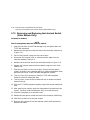
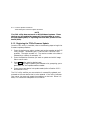
2.2.3.1 Manually Unloading a Cartridge from the Drive
If a cartridge does not unload from the tape drive when you press the
Load/Unload or Eject button on the operator control panel, you can
remove the cartridge manually by first pressing the Unload button on
the drive. If this step fails, manually rewind the tape to unload the
cartridge.
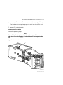
To manually rewind the tape, refer to the following procedure (this
procedure assumes that you have already removed the drive from its
enclosure):
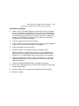
1. Turn the drive on its side; note the hole in the circuit board toward
the front of the drive.
2. Turn the screw inside the hole counterclockwise, using a Phillips
screwdriver.
3. Rewind the tape until it unloads into the cartridge.
4. Pull the solenoid out and lift the handle to eject the cartridge.
Return the cartridge to its original storage position in the magazine.
You can determine the original position by looking at the front of the
magazine (Figure 2–2). The first empty slot that has a metal flag showing
is the slot from which the cartridge should have originated. Insert the
cartridge from the rear of the magazine. Be sure the write-protect switch
is adjacent to the slot number on the front of the magazine to ensure that
its position is the same as those of the other cartridges.
NOTE
Be sure to check the cartridge for any damage that may have
occurred.
Operating Procedures
Using the Slot Select, Load/Unload, and Eject Buttons
Figure 2–2 Front View of the TF/TZ 800-series Magazine
0
1
2
3
4
5
6
SHR_X1023A_89
2–7
2–8 Operating Procedures
Using the Slot Select, Load/Unload, and Eject Buttons
2.2.4 Opening the Receiver
The Eject button opens the receiver for insertion or removal of the
magazine. It is disabled when the Mode Select key is in the OCP Disabled
position. The Eject button can also be used to unload a cartridge from the
drive.
NOTE
When a cartridge is not in the drive, the Slot Select, Load/Unload,
and Eject indicators are on before any operation begins. Pressing
the Eject button causes all indicators to turn off. The elevator
then returns to its home position, and the receiver opens.
When a cartridge is in the drive, the Eject and Load/Unload
indicators are on before the operation begins. When you press the
Eject button, both indicators turn off, and the cartridge unloads
from the drive and returns to the magazine. The receiver then
opens to allow access to the magazine.
In both situations, once the receiver is closed again, a magazine
scan begins, and the indicators turn back on when the scan is
complete.
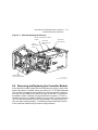
2.3 Magazine
This section describes how to remove the TF/TZ 800-series magazine from
the receiver, load and unload cartridges into and from the magazine, and
restore a magazine to the receiver.
2.3.1 Removing the Magazine from the Receiver
To remove the magazine from the TF/TZ 800-series subsystem, first be
sure that:
•
The Power On indicator is on (Figure 2–1).
•
The Eject indicator is on before you press the Eject button.
Then:
1. Press the Eject button to open the receiver.
2. Grasp the receiver and gently pull it forward to access the magazine.
Operating Procedures
Magazine
2–9
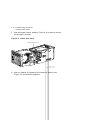
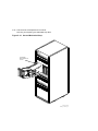
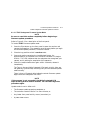
3. Grasp the magazine’s handle and lift the magazine out of the receiver
(Figure 2–3).
Figure 2–3 Removing the Magazine from the Open Receiver
Ejec
Loa
Slot
Pow
Wri
nloa
Sele
d
ct
er O
n
te P
ro
Tap
tect
e In
Use
Driv
Loa
t
d/U
e Fa
ult
d Fa
u
lt
SHR-X0045-90
2–10 Operating Procedures
Magazine
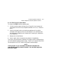
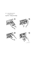
2.3.2 Inserting Cartridges into the Magazine
To insert a cartridge use the following steps:
1. Grasp the cartridge with the CompacTape III label up and the writeprotect switch toward you (Figure 2–4).
2. Set the cartridge’s write-protect switch to the appropriate position.
3. Push the cartridge into the slot until it stops and you hear a click.
(Figure 2–5).
Operating Procedures
Magazine
2–11
Figure 2–4 Write-Protect Switch on the CompacTape III
ORANGE
INDICATOR
TM
m
Co
pa
cT
e
ap
III
WRITEPROTECT
SWITCH
WRITEENABLED
WRITEPROTECTED
SHR_X1020C_89
ZKO-1285-03-DG
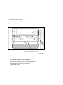
2–12 Operating Procedures
Magazine
Figure 2–5 Inserting a Cartridge into the Front of the Magazine
BACK OF
MAGAZINE
0
1
2
3
4
5
5
6
1
2
3
0
0
1
1
2
2
3
3
4
4
5
5
6
6
NOTE: Push tape in
until a click is heard
SLOT
NUMBERS
0-6
FRONT OF
MAGAZINE
ZKO-1217-05-DG
Operating Procedures
Magazine
2–13
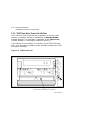
2.3.3 Removing a Cartridge from the Magazine
To remove a cartridge from the magazine, push the cartridge farther into
the slot; then release. This releases the cartridge from the magazine
(Figure 2–6).
NOTE
Never apply labels to the top or bottom of tape cartridges. Doing
so can cause the cartridge to jam in the magazine.
NOTE
Never move the metal tab on the left side of the magazine slot in
an attempt to remove the cartridge. This will cause a magazine
fault.
2.3.4 Restoring the Magazine to the Receiver
To restore the magazine to the receiver:
1. Slide the magazine into the receiver. (Since the magazine is slotted,
you can restore it only in the correct orientation.)
2. Push the receiver closed, ensuring that it is fully closed before
proceeding.
2–14 Operating Procedures
Magazine
Figure 2–6 Removing a Cartridge from the Front of the Magazine
BACK OF
MAGAZINE
0
1
2
NOTE: Push tape in
until a click is heard
3
4
5
6
1
2
3
0
1
0
2
1
3
2
4
4
3
5
5
4
6
5
6
SLOT
NUMBERS
0-6
FRONT OF
MAGAZINE
ZKO-1217-06-DG
Operating Procedures
Mode Select Key
2–15
2.4 Mode Select Key
The mode select key (Figure 2–1) locks the loader transfer assembly into
the enclosure and also locks the magazine into the receiver.
2.4.1 Operating Modes
The following modes are for operational use:
•
OCP Disabled mode — Automatically loads and unloads cartridges
as necessary during backup procedures. When you insert the
magazine into the receiver and close the receiver, the loader scans
the magazine. The first cartridge in the magazine automatically loads
into the drive.
Operations stop if you are copying data to tape and either the storage
capacity of the last cartridge is exceeded, or no cartridge is in the next
sequential slot in the magazine.
To lock the TF/TZ 800-series subsystem into the enclosure and lock
the receiver, set the mode select key to OCP Disabled mode. The
OCP pushbuttons are disabled.
•
Automatic mode — Is the default, or ‘‘normal,’’ mode of the TF
/TZ 800-series magazine tape subsystem. This mode automatically
loads and unloads cartridges as necessary during backup procedures.
Operations stop if you are copying data to tape and either the storage
capacity of the last cartridge is exceeded, or no cartridge is in the next
sequential slot in the magazine.
To lock the TF/TZ 800-series subsystem into its normal operating
position in the enclosure but leave the receiver unlocked, set the mode
select key to Automatic mode. The receiver can be opened and the
OCP pushbuttons are enabled.
•
Manual mode — Automatic loading and unloading of cartridges does
not occur. You must press the Load/Unload button to move cartridges.
This mode is most useful for, but not restricted to, copying specific
files to or from tape.
To lock the TF/TZ 800-series subsystem into the enclosure, set the
mode select key to Manual mode. The receiver is unlocked and can
be opened; the OCP pushbuttons are enabled.
NOTE
During Manual mode, the cartridge returns to the magazine,
but the current slot indicator does not advance to the next
available cartridge.
2–16 Operating Procedures
Mode Select Key
2.4.2 Service Mode
Use Service mode to perform head cleaning and servicing procedures.
To unlock the TF/TZ 800-series subsystem from its enclosure and remove
it from its normal operating position, set the mode select key to Service
mode. The receiver is unlocked and can be opened. On newer models, the
rear ship lock must be unscrewed first.
Newer models have one mechanical stop associated with Service Mode
(Figure 2–7), while other models have two mechanical stops associated
with Service mode (Figure 2–8).
Figure 2–7 Mechanical Stops Associated with Service Mode (Newer
Models)
MECHANICAL
STOP
SHR-X0147C-90-CPG
ZKO-1285-04-DG
On models with two mechanical stops, the first stop lets you pull the front
chassis forward from the enclosure to:
•
Remove a faulty loader transfer assembly
Operating Procedures
Mode Select Key
2–17
Figure 2–8 Mechanical Stops Associated with Service Mode (Older
Modes)
FIRST
MECHANICAL
STOP
SECOND
MECHANICAL
STOP
SHR-X0147C-90-CPG
ZKO-1285-05-DG
•
Remove a faulty operator control panel
•
Remove a faulty power supply assembly
•
Perform the head cleaning procedure
Press the first stop to access the second stop. You can then pull the rear
chassis forward from the cabinet. This position provides access to the
following field replaceable units (FRUs):
•
Tape drive
•
Handle motor assembly
•
Controller module
For specific instructions on how to access the internal assemblies of the
TF/TZ 800-series subsystem, see Chapter 6.
2–18 Operating Procedures
Initialization and Power-On Self-Testing
2.5 Initialization and Power-On Self-Testing
This section describes the initialization of the subsystem, and the
component power-on self-tests (POSTs) that occur when you power on
the TF/TZ 800-series subsystem.
At power-on, the following components run simultaneous, but separate,
self-tests:
•
Loader transfer assembly
•
TK85 tape drive
•
Controller module
The following subsections show the sequence in which the initialization
occurs.
2.5.1 Power-On Self-Test
At power-on, the loader transfer assembly runs its own self-test. All
operator control panel (OCP) indicators are on. After a successful
completion of the self-test, the Loader Fault and Magazine Fault
indicators turn off while all others remain on. This self-test completes
in about five seconds.
2.5.2 Initialization of the Loader Transfer Assembly
When the controller module completes its self-test successfully, it
initializes the loader transfer assembly, and all OCP indicators turn
on. This occurs about 10 seconds after power-up.
If no errors occur, the controller module turns off the OCP indicators
(except for Power On) and initiates a magazine scan.
The magazine scan causes the elevator to move to each cartridge slot,
moving each cartridge slightly in its position. The associated slot
indicator then turns on. This process completes in about 60 seconds,
depending on the number of cartridges in the magazine.
Operating Procedures
Initialization and Power-On Self-Testing
2–19
2.5.3 Completion of Controller Initialization
Upon successful execution of loader transfer assembly initialization by
the controller module, and assuming the TF857/TF867 subsystem has a
magazine with a cartridge in slot 0, the following indicators turn on:
•
Power On
•
Eject
•
Load/Unload
•
Slot Select
•
Slot 01
If the mode select key is not in the OCP Disabled mode, the Slot Select,
Load/Unload, and Eject buttons are enabled.
If the controller module detects a loader transfer assembly or tape drive
error during its initialization, the OCP Loader Fault and current slot
indicators display the device in error.
NOTE
If the above initialization sequence does not complete
successfully, check the results of the controller module and
tape drive self-tests. If the controller module self-test completed
successfully, you can diagnose failures in the drive or subsystem
by using the DUP diagnostic programs in Chapter 6.
2.5.4 Controller Module Self-Test
A successful self-test is verified by the eight indicators on the controller
module. (You must open the loader transfer assembly to observe these
indicators.) The indicator on the far left is on; the remaining indicators
blink in a rotating pattern.
If the self-test is not successful, some or all of the indicators are on
steadily in a fixed pattern. The error indicators reflect the last self-test
error detected.
Once the controller module completes a successful self-test, it connects to
the host system, during initialization, through a DSSI or SCSI bus.
1
Or the indicator of the first available slot turns on.
2–20 Operating Procedures
Initialization and Power-On Self-Testing
2.5.5 TK85 Tape Drive Power-On Self-Test
The TK85 drive runs its self-test during power-on or during a reset
process. A successful self-test is indicated by the Operate Handle
indicator being on if no cartridge is installed or by the Tape in Use
indicator being on if a cartridge is installed (Figure 2–9).
If the self-test is not successful, all indicators on the TK85 front panel
blink. (You must open the loader transfer assembly to observe the TK85
front panel indicators.)
Figure 2–9 TK85 Front Panel
se
U
ed
g
e
ct
in
in
at dle
n
te te
e
e a pe per an
ri ro
ap Us Cle Ta
W P
O H
T
Text is 8pt on 8pt
Rt,z,-45
TK85 is TI med (ti) 12pt
t
ad
gh
Lo
Li
o
T
t
ai his
t
W
n
pe
O dle pe
a
T
an
H
rt
se his
t
In
se
lo e
C dl
an
H
R
d
oa
on
nl
t
U
ut t
o
B gh
T
i
ss L
re
P t
is
ai
th
W
n
pe
pe
O dle Ta
an ve
o
em
H
U
nl
oa
d
CARTRIDGE INSERT/RELEASE HANDLE
SHR-X0056B-90
3
Local Programs and Utilities
This chapter describes how to access local programs and utilities using
the SET HOST/DUP command.
NOTE
The system manager can provide you with the specific privileges
needed to access these programs and utilities.
The local programs and utilities described in this chapter are:
•
DIRECT (Directory) — Lists the available local programs
(Section 3.2).
•
HISTRY (Historical Statistical Data) — Displays information about
the TF857 subsystem (Section 3.3).
•
PARAMS (Parameter Configuration Utility) — Displays or changes
subsystem parameters (Section 3.4).
•
DRVEXR (Drive Exerciser) — Exercises the tape drive (Section 3.5).
•
DRVTST (Drive Test) — Verifies the correct functioning of subsystem
hardware (Section 3.6).
•
LDRTST — Exercises the internal mechanism of the loader transfer
assembly and the drive (Section 3.7).
NOTE
To abort from a local program or utility, enter Ctrl/Y , Ctrl/C , or
CTRL \ . Do not stop diagnostics by pressing the Load/Unload
button. Doing so can cause system failure.
3–1
3–2 Local Programs and Utilities
Accessing Local Programs
3.1 Accessing Local Programs
Access local programs with the VMS command:
$ SET HOST/DUP
This command allows access to local programs that reside in readonly memory (ROM) on the TF857/TF867 subsystem. Communications
between the host system and the TF857/TF867 subsystem are through
the diagnostic utilities protocol (DUP). Drive operations under DUP
are controlled through the local programs. When you exit the program,
control returns to the operating system.
The following example shows the sequence of commands to access local
programs. These commands are used with the VMS operating system,
version 5.4.2 or later:
$ SHOW CLUSTER
; To learn the node name
; of the tape device.
$ SET DEVICE/noavailable device-name ; To make the device
; unavailable to users.
$ SET HOST/DUP/SERVER=MSCP$DUP/TASK=PARAMS nodename
You can add the /LOG qualifier to the above commands to generate a log
file.
You can substitute any of the previously listed programs and utilities after
the /TASK qualifier.
NOTE
A typical example of a device node name is T7X3MA. This default
node name is derived from the module serial number. You can
change this node name by using the PARAMS utility; however, if
you change the node name, you need to reboot the host system.
Local Programs and Utilities
Accessing Local Programs
3–3
3.1.1 Error Message after Executing SET HOST/DUP
You may receive the following error message after issuing the SET HOST
/DUP command:
Unit Offline
Data Pattern:
Record Byte Count:
Program Object Count:
Tape Object Count:
0
24732
13988
13987
End Message
000A036E 00040000 A1000023 00000000 00000000 00000000 00000000 00000000
00000000 00000000 00000000 00000000 00000000 00000000 00000000 00000000
Statistical Report
Test Name: FTST03, Pass 16
Random Seed:
1242755630
Byte Count:
0
Pattern Number:
9
Data Errors:
Read
Write
Retries:
4
0
ECC:
0
Hard:
0
0
Data Compare Errors:
0
Mispositions:
0
Kbytes Written:
10380731
Read: 10182195
0023 - Unit read/write test failed.
If you receive an error message, you may need to load the FYDRIVER
program, as follows:
$ MCR SYSGEN
; To access SYSGEN.
$ SYSGEN> LOAD FYDRIVER
; To load FYDRIVER, prerequisite
; to using diagnostics.
$ SYSGEN> CON FYA0/NOADAP ; To configure FYDRIVER.
$ SYSGEN> EXIT
3–4 Local Programs and Utilities
DIRECT Program
3.2 DIRECT Program
The DIRECT program provides a directory of the diagnostic and utility
programs that are resident in the TF857/TF867 subsystem. The following
examples were taken from a TK857.
An example of a DIRECT display follows:
DIRECT V1.0 D
HISTRY V1.0 D
PARAMS V1.0 D
DRVEXR V1.0 SD
DRVTST V1.0 SD
LDRTST V1.0 SD
Completed
3.3 HISTRY Program
The HISTRY program displays information about the history of the TF857
/TF867 subsystem.
An example of the HISTRY display follows:
TF85
DSSI: T8992Q /2 (DIPs)
Controller:
S: EN03000159
HW: 000/PCB-rev:A000
Bt: 120/42DA8D6A (23-JAN-1991 15:00:47)
Cd: 129/AF19579E ( 7-FEB-1991 15:24:43)
EE: 085 TD: 002
Drive:
S: EN02900321
HW: 004/A00
Cd: 030/4AEC
EE: 015/42CA
Loader (S/H/M): 023/000/000
Power on Hours:
1
Power Cycles:
3
Completed
Local Programs and Utilities
PARAMS Utility
3–5
3.4 PARAMS Utility
Use the PARAMS utility to display or change internal parameters. The
TF857 subsystem’s parameters are preset during manufacturing but can
be changed by a system manager or operator.
Table 3–1 lists some subsystem parameters used with the PARAMS
utility.
Table 3–1 Summary of TF857/TF867 Subsystem Parameters
Parameter
Definition
UNITNUM
TMSCP unit number.
SYSTEMID
Controller module’s 48-bit system ID.
NODENAME
Node name for the TF857 subsystem.
FORCENAME
1 — Default node name in use. (Derived from the subsystem
serial number.)
0 — Uses value set in NODENAME.
FORCEUNI
Determines whether the TMSCP unit number or DSSI node
ID is used.
1 — Uses the DSSI node ID.
0 — Uses the TMSCP unit number.
FORCEDENSITY
Determines what the tape density will be.
0 — Automatic, as selected by the host.
1 — Low (TK85) density regardless of host selection.
2 — High (TK86) density regardless of host selection.
3.4.1 Selecting Density with the TF867
To write in TK85 format (low density) on a TF867 subsystem, you can use
the PARAMS utility on a VMS system, To modify the density use the DUP
parameter FORCEDENSITY.
The DUP parameter FORCEDENSITY controls how a TF867 subsystem
determines what density to use when writing from BOT. See Table 3–1 for
parameter settings.
3–6 Local Programs and Utilities
PARAMS Utility
NOTE
When using the FORCEDENSITY parameter be sure to change the
value back to 2 after you have finished using the TK85 format tape
operation.
3.4.2 Displaying, Setting, and Saving Parameters
At the PARAMS> prompt, use the following command to display, set, or
save parameters:
•
SHOW parameter — Displays a specific parameter. You can
add qualifiers to the SHOW command to list specific subsystem
parameters, such as:
SHOW
SHOW
SHOW
SHOW
SHOW
SHOW
SHOW
/ALL
/DIF
/DSSI
/DUP
/TDS
/TMSCP
/SYSTEM
NOTE
Be sure to leave a space between the SHOW command and the
/qualifier.
•
SET parameter — Sets a parameter.
•
WRITE — Saves parameter modifications.
•
STATUS — Displays the status of the subsystem.
•
HELP — Lists available PARAMS commands.
•
EXIT — Ends the PARAMS session.
3.4.2.1 SHOW command
To display specific parameters, in this example, system parameters:
PARAMS> SHOW /SYSTEM
The system displays:
Local Programs and Utilities
PARAMS Utility
3–7
Parameter
Current
Default Minimum Maximum
Radix
--------------- -------------- -------------- -------- -------- ------FORCEEEREBUILD
0
0
0
1 Decimal
CNTHWREV
0
0
0
255 Decimal
HWREVSTRING
"PCB-rev:????" "PCB-rev:????"
Ascii
RGTTAG
"??????"
"??????"
Ascii
UNITID
454E0044ABD7
Quad
3.4.2.2 SET Command
Use the SET command to set, or change, internal TF857 subsystem
parameters.
To use the SET command, enter:
PARAMS> SET parameter value
In the previous example, parameter is the name of the parameter to
be set, and value is the value you want assigned to the parameter. See
Section 5.4.4 for more information.
3.4.2.3 WRITE Command
Use the WRITE command to save, in nonvolatile memory, the changes
you made using the PARAMS utility and its commands. The WRITE
command is similar to the VMS SYSGEN WRITE command.
3.4.2.4 STATUS Command
The STATUS command provides status about the operation of the
subsystem.
3.4.2.5 HELP Command
Use the HELP command to display a list of available PARAMS
commands:
EXIT
HELP
SET {parameter | .} value
SHOW {parameter | . | /class}
/ALL
/DIF
/DSSI
/DUP
/SYSTEM
/TDS /TMSCP
STATUS DATALINK {Reset}
STATUS PATH node_number {Reset}
STATUS LOGS
WRITE
3–8 Local Programs and Utilities
PARAMS Utility
3.4.2.6 EXIT Command
Enter EXIT to end the PARAMS session.
NOTE
If you change the parameters, the system displays the following
message after you type EXIT at the PARAMS> prompt.
Parameter modified but not written. Still Exit?
If you answer YES, the system returns to the VMS prompt and
your modifications are not saved. If you answer NO, the system
returns to the PARAMS> prompt. To save your modifications,
enter WRITE at the prompt, and then EXIT. See Section 3.4.2.3 for
more information on the WRITE command.
3.5 DRVEXR Progam
The DRVEXR program exercises the TK85 tape drive. It is an intensive
data transfer test and indicates the overall integrity of the drive. An
example of a DRVEXR display follows:
Write/read anywhere on medium? [1=Yes/(0=No)] 1
User Data will be corrupted. Proceed? [1=Yes/(0=No)] 1
Test Time in Minutes [(10) - 100] 10
Minutes to Complete: 10
Statistical Report
Test Name: DRVEXR, Pass 1
Random Seed:
1111227776
Byte Count:
0
Pattern Number:
0
Data Errors:
Read
Write
Retries:
0
0
ECC:
0
Hard:
0
0
Data Compare Errors:
0
Mispositions:
0
Kbytes Written:
228461
Read:
0
Test Passed
NOTE
The DRVEXR program prompts you for an execution time; the
DRVTST program displays a specific execution time.
Local Programs and Utilities
DRVTST Program
3–9
3.6 DRVTST Program
The DRVTST program is a pass/fail test that invokes a comprehensive
test of the TK85 tape drive hardware. No statistics are sent to the host
upon completion of this test. Testing terminates with either a Test Passed
message or a fatal error message. An example of a DRVTST display
follows:
Write/read anywhere on medium? [1=Yes/(0=No)] 1
User Data will be corrupted. Proceed? [1=Yes/(0=No)] 1
Minutes to Complete: 25
Test Passed
3.7 LDRTST Program
The LDRTST program sends commands to the loader electronics module,
which exercises the mechanics of the loader transfer assembly and the
read/write ability of the drive. This test also checks the status of each
cartridge in the magazine. An example of a LDRTST display follows:
Passes [(0) - 65535]: 1
Loader Exerciser
Loopback Test: Passed
Illegal Command Test: Passed
Internal Self Test
ROM Test: Passed
RAM Test: Passed
EEPROM Test: Passed
CTC Test: Passed
UART Test: Passed
Movement Test
Picker Arm Test: Passed
Cartridge Motor Test: Passed
Handle Motor Test: Passed
Elevator Test: Passed
Unit Available
Cartridge loads:
Unit Available
1
Cartridge loads:
Unit Available
2
Cartridge loads:
Unit Available
3
Cartridge loads:
Unit Available
4
Cartridge loads:
Unit Available
5
Cartridge loads:
Unit Available
6
Statistical Report
3–10 Local Programs and Utilities
LDRTST Program
Test Name: LDRTST, Pass 1
Random Seed:
0
Byte Count:
0
Pattern Number:
0
Data Errors:
Read
Write
Retries:
0
0
ECC:
0
Hard:
0
0
Data Compare Errors:
0
Mispositions:
0
Kbytes Written:
0
Test Passed
Read:
0
4
Troubleshooting Procedures
This chapter describes failures that are not detectable through
diagnostics, error conditions, magazine and loader faults, power problems,
and cartridge motion faults.
4.1 Avoiding Basic Problems
Follow these guidelines when operating the TF/TZ 800-series subsystem
to avoid basic problems:
•
Use CompacTape III cartridges or for read-only operations, use
CompacTape or CompacTape II cartridges.
•
Check the tape leader in the cartridge by lifting the cartridge latch
that opens the door to expose the leader. Be sure the leader is in the
same position as the one shown in Figure 4–1.
CAUTION
Do not touch exposed portions of the magnetic tape. If the
tape leader is not in the correct position, use a new cartridge.
•
Be sure that the receiver is fully closed and the current slot indicator
is on for the starting cartridge.
•
Be sure that no slots in the magazine are empty between the
starting cartridge and the expected completion cartridge.
NOTE
The TF/TZ 800-series subsystem unloads and loads the next
cartridge when the subsystem receives a DISMOUNT command
from the host system.
4–1
4–2 Troubleshooting Procedures
Avoiding Basic Problems
Figure 4–1 Opening the Cartridge Door to Check the Tape Leader
CARTRIDGE
LEADER
DOOR LOCK
(RELEASE BY LIFTING
DOOR LOCK WITH THUMB)
SHR-0002-86
SHR_X1027_89_CPG
4.2 Backup Operation Failure
Some manual operations, if not performed correctly, may cause backup
operations to fail:
•
Loading CompacTape or CompacTape II cartridges when executing
write operations
•
Loading write-protected CompacTape III cartridges when executing
write operations
•
Selecting the incorrect cartridge slot.
Troubleshooting Procedures
Nondetectable FRU Failure
4–3
4.3 Nondetectable FRU Failure
Table 4–1 describes situations that can occur with field replaceable unit
(FRU) failures not detectable through diagnostics. These failures may
cause subsystem failure.
Table 4–1 Nondetectable FRU Failures
FRU
Possible Failure
Interlock switch
1
After you slide the TF/TZ 800-series
subsystem forward for head cleaning or
service, the Power On indicator remains
on.
Tape drive communications cable
After you replace either a faulty drive or a
loader transfer assembly, the power is on,
but the subsystem still fails.
Handle motor assembly
Same as above. Characterized by
subsystem retry errors.
Power supply assembly
When connected to a known good source
of power, and the power switch is set to 1
(on), the subsystem does not power up and
the Power On indicator remains off.
Operator control panel
After you replace either a faulty
controller module or other FRU, the
OCP pushbuttons or the indicators do not
function. (All indicators turn off briefly at
power-on.)
Fan
Inspection required.
1 Applies
only to older models
See Chapter 6 for information on removing and replacing faulty FRUs.
4–4 Troubleshooting Procedures
Error Conditions
4.4 Error Conditions
This section describes error conditions, failure influences, and soft error
rates. In addition, it includes information on magazine and loader faults.
See Table 4–2 for a list of common failures, causes, and corrections.
4.4.1 Detecting Common Failure Influences
Many factors may influence failures, for example:
•
Defective media
•
Operator or user errors
•
Incorrect backup commands
•
Poor power or grounding
NOTE
The tape drive may appear to be the failing unit due to the
operation being performed at the time of failure (such as backup).
However, before you replace the drive, ensure that any problems
you find are not due to the above factors.
4.4.2 Soft Errors
Soft errors are normally considered to be events rather than errors. In
the case of soft errors, no data is lost. For a write operation, the data is
rewritten. For a read operation, retries are performed.
Some of the variables that create soft errors are as follows:
•
Media dropouts
•
Temperature of media (not acclimatized)
•
System bus activity
•
Applications
•
Head wear
•
Contamination
•
Foreign debris in tape path
Troubleshooting Procedures
Error Conditions
4–5
Changes in soft error rates for any particular drive and cartridge are
more significant than an absolute number of soft errors. This is due to
the variables described in table Table 4–2.
When examining the drive error count, you can detect soft and hard
errors. For example, an error occurs if you give the wrong label name
during a mount. Be sure the errors indicate a real hardware problem
before replacing the drive.
NOTE
All tapes contain a number of dropouts. Although these are
imperfections in the tape, the tape is not considered to be
defective. The hardware and software are designed to deal
with these known imperfections. Dropout testing is performed
on samples of media by Digital’s vendors and meet all of the
specifications of Digital Equipment Corporation.
4.4.3 Common Failures
Refer to Table 4–2 for a list of common failures, their probable causes and
possible corrections.
Table 4–2 Common Failures, Causes, and Corrections
Symptom
Probable Cause
Possible Fix
Failure to mount or
initialize with new
media
Bad media or dirty
head
Clean the head and retry
with another cartridge.
OCP pushbutton
indicators blinking
Drive failed POST or
detected a hard error
during operation
Attempt to clear the error
by pressing the Unload
button on the drive. If
the error does not clear,
you have a drive hardware
failure or a power problem.
4–6 Troubleshooting Procedures
Error Conditions
Table 4–2 (Continued) Common Failures, Causes, and Corrections
Symptom
Probable Cause
Possible Fix
Green indicator on
drive blinking
Drive leader unhooked
in drive
Clear the error by pressing
the Unload button on the
drive or the Load/Unload
button on the OCP.
Calibration error
Mispositioned
cartridge leader
Inspect the cartridge leader
for correct position. Do not
use the cartridge if you
cannot reposition the leader
(Figure 4–1).
Try another cartridge. If
the error repeats, you have
a drive hardware failure or
more than one bad cartridge
(physically damaged or bad
calibration tracks).
Cartridge stuck in
drive with tape on
takeup reel
Hard drive error
Attempt recovery by
pressing the Unload button
on the drive, or manually
remove cartridge from the
drive (Section 2.2.3.1).
4.5 Magazine and Loader Faults
Error indications fall into two main categories:
•
Magazine Fault — An operator-correctable condition in most cases,
and is indicated by the Magazine Fault indicator being on.
•
Loader Fault — A condition that is indicated by the Loader Fault
indicator being on, and most likely requires service from Customer
Services.
4.5.1 Magazine Fault Description
A magazine fault is indicated by the Magazine Faults LED on and Eject
LED on. A magazine fault can occur when:
1. A cartridge has been removed from the magazine incorrectly.
2. A cartridge was manually unloaded from the drive.
3. A cartridge which was loaded into the drive by the loader was
manually unloaded and put back into the magazine.
Troubleshooting Procedures
Magazine and Loader Faults
4–7
4. A cartridge was manually inserted into the drive.
NOTE
This can only occur if the loader has been opened, requiring
service intervention. This cannot occur under normal
operation
Detecting case 1, 2, 3. These can be detected by the Magazine Fault LED
on and slot LEDs 0 and 5 on.
First a cartridge should never be removed from the magazine by moving
the metal tab in front of the cartridge. This is the main source of
magazine faults. Use the proper cartridge insertion/removal procedure
(reference section 2.3.2, 2.3.3) to clear a magazine fault caused by case 1,
2, and 3:
•
Press the Eject button to open the receiver.
•
Remove the magazine and check for a metal tab over an open slot.
This is the slot from which the cartridge was removed.
If a metal tab is found over a open slot then:
Reinsert the missing cartridge properly, pushing the cartridge
in until it snaps in place. If no cartridge is needed in this slot,
push a cartridge into the slot and then remove it according to the
normal cartridge insertion/removal procedure. This setp is critical
to avoid additional magazine faults.
Insert the magazine into the receiver.
Close the receiver.
•
If no metal tab is covering and empty slot, then the cartridge
loaded into the drive was manually removed and re-inserted into
the magazine.
To clear this case simply close the receiver.
Detecting case 4, the cartridge was manually loaded into the drive. This
can be detected by the Magazine Fault LED on and slot LEDs 0 and 6 on.
This is the only time LEDs 0 and 6 will be on.
To clear the Magazine Fault caused by case 4:
•
Press the Eject button to open the receiver
•
Remove the magazine
4–8 Troubleshooting Procedures
Magazine and Loader Faults
•
Reach in and manually unload the tape from the drive by pressing the
unload button.
•
When the drive beeps and the green operate handle LED comes on
the cartridge can be manually removed by lifting the drive handle.
•
Remove the cartridge.
•
Reinsert the magazine and close the receiver.
4.5.1.1 Clearing a Magazine Fault
To clear a magazine fault, press the Eject button to open the receiver and
remove the magazine. Remove the cartridge from the drive or elevator if
present. Close the receiver, and the drive controller clears the magazine
fault. While the magazine is out, make sure there are no retention flags
showing in a empty slots. After the fault has cleared, try loading and
unloading cartridges to verify operation.
4.5.2 Loader Fault Description
A loader fault indicates that the TF/TZ 800-series subsystem has detected
a fatal error in either the loader transfer assembly or the tape drive. In
the case of some loader transfer assembly errors, the subsystem attempts
three retries before declaring a fatal error. All loader faults generate
an error log, cause the Loader Fault indicator to light, and generate an
associated subcode.
The Loader Fault indicator displays both loader and drive errors. The
presence of a fault is indicated by the following slot indicators:
•
Slots 4 and 0 light to indicate a controller module fault.
•
Slots 5 and 0 light to indicate the loader detected a fault.
•
Slots 6 and 0 light to indicate a drive fault.
NOTE
Error indicators do not blink. During hardware failures, action is
determined by the controller module.
4.5.2.1 Clearing a Loader Fault
When a loader fault occurs, the Load/Unload and Eject indicators are on.
When you press the Load/Unload button, the TF/TZ 800-series subsystem
attempts to clear the error. When you press the Eject button, the receiver
opens to let you access the magazine.
Troubleshooting Procedures
Power Problems
4–9
4.6 Power Problems
If the Power On indicator is not on, or the host system does not recognize
the TF/TZ 800-series subsystem:
•
Verify that the subsystem is seated completely into the enclosure.
(Power to the loader transfer assembly is disabled when the
subsystem is positioned forward.)
•
Verify that the subsystem configuration is correct.
4.7 Cartridge Motion Faults
Occasionally, a cartridge motion fault can occur in the elevator or drive
mechanism. A cartridge motion fault is indicated when:
•
The Magazine Fault indicator on the operator control panel is on.
•
A cartridge cannot be loaded or unloaded.
•
An unusual sound is in the motor.
This section describes how to remove cartridges from a loader transfer
assembly without harming the loader or data. It does not provide
information on fault-finding, repair, or maintenance of the loader.
4.7.1 Isolating Cartridge Motion Faults
Most cartridge motion problems result from worn or damaged magazines
or cartridges.
To isolate cartridge motion faults:
1. Set the Mode Select key to Automatic mode, returning the subsystem
to its ‘‘normal’’ mode.
2. Attempt to reproduce the error.
4–10 Troubleshooting Procedures
Cartridge Motion Faults
3. Open the loader transfer assembly (Figure 4–2) to locate or remove
the cartridge in question.
Figure 4–2 Loader Open Latch
LOADER OPEN LATCH
SHR-0007-90
SHR-X0140-90-CPG
4. Open the receiver by squeezing the mechanical ejection lever
(Figure 4–3) to remove the magazine.
Troubleshooting Procedures
Cartridge Motion Faults
4–11
Figure 4–3 Mechanical Ejection Lever
DRIVE COMMUNICATIONS
CABLE
FIRST
MECHANICAL
STOP
MECHANICAL
EJECTION LEVER
SECOND
MECHANICAL
STOP
SHIPPING
RESTRAINT
SHR-0012-90
SHR-X0147C-90-CPG
5. Insert the cartridge into the magazine from the rear, replacing the
cartridge in its original slot (the metal tab next to the slot number
indicates the original slot).
NOTE
The subsystem may indicate a magazine fault due to reinserting
the cartridge into the magazine as described in the preceding
process. To clear this magazine fault, remove the magazine from
the receiver and close the receiver. When the Eject indicator
turns on, insert the magazine back into the subsystem.
The OCP indicators signal when you can cycle cartridges into and out of
the drive. Concentrate on the cartridge in question, but be sure to test
the others as well. There should be no difference in the action taken by
the mechanics due to an OCP or system command.
4–12 Troubleshooting Procedures
Cartridge Motion Faults
4.7.2 Recovering Cartridges
Cartridge motion problems may be caused by a fault in one of the
following components. Suggestions for recovering cartridges follow:
•
Magazine — Cartridge motion problems that are caused by faulty
magazines are usually indicated by problems occurring during the
attempt by the elevator to return the cartridge to the magazine.
Replace the magazine and see if the problem persists. Note that you
may not be able to find a magazine problem by inspection alone. For
example, a damaged surface finish in or near a slot, causing excessive
friction, may not be obvious.
•
Cartridge — Cartridge motion problems that occur with one
cartridge only are likely to be caused by that particular cartridge.
Move the cartridge to another slot and note if the problem occurs
there as well. In addition, faulty cartridges can cause problems in the
drive area. Check the leader positioning in both drive and cartridge,
and the operation of the cartridge door.
•
Tape drive or handle motor assembly — Cartridge motion
problems caused by a faulty or misaligned tape drive occur when the
tape is loaded into or unloaded from the drive. Check for problems in
the tape drive door or tape drive alignment. See Chapter 6 to ensure
that the handle motor assembly is correctly assembled and in the
correct position.
•
Loader transfer assembly — Faults caused by the loader transfer
assembly are usually not field repairable. Replacement of the loader
transfer assembly is required.
5
FRU Removal and Replacement
Procedures
This chapter describes how to remove and replace the field replaceable
units (FRUs) of the TF/TZ 800 subsystem. The chapter also provides lists
of recommended spares and service aids.
The TF857/TF867 subsystem FRUs can be removed without interrupting
the host system or breaking the DSSI bus. You can power down the
subsystem and take it off-line without interfering with the host or any
other DSSI device.
The TZ857/TZ867 subsystem FRUs cannot be removed unless the system
is powered down.
For a list of the FRUs and references to their removal and replacement
procedures, see Table 5–1. For guidelines to removing and replacing the
FRUs, see Section 5.2.
5–1
5–2 FRU Removal and Replacement Procedures
Table 5–1 Field Replaceable Units and Related Procedures
FRU
Procedure Section
Controller module
5.4
Loader transfer assembly
5.5
Tape drive
5.6
Tape drive takeup leader
5.7
Operator control panel
5.8
Fan
5.9
Interlock switch
5.10
Power supply assembly
5.11
Handle motor assembly
5.12
Key lock switch
5.13
FRU Removal and Replacement Procedures
Recommended Spares and Service Aids
5–3
5.1 Recommended Spares and Service Aids
Table 5–2 lists the part numbers of the recommended spares. It includes a
description of each spare with a reference to a figure showing the spare.
Table 5–2 Recommended Spares List
Part
Number
Description
Figure
TK85–AX
TK85 cartridge tape drive, 2.6 gigabytes
5–1
TK86–AX
TK86 cartridge tape drive, 6.0 gigabytes
5–1
54–19089–01
Controller module (DSSI)
5–1
54–19122–01
Controller module (SCSI)
5–1
70–28824–01
Takeup leader kit
5–14
17–02613–01
Drive communications cable
5–3
29–28102–01
Loader transfer assembly
5–1
29–28103–01
Power supply 110 Vac, 50/60 Hz
5–1
29–28103–02
Power supply 220 Vac, 50/60 Hz
5–1
29–28104–01
Operator control panel
5–1
29–28106–01
Handle motor assembly
5–1
29–28105–01
Interlock switch (older models only)
5–1
29–28972–01
Loader transfer assembly communications
cable — 10-pin cable connecting to drive
controller
5–7
29–28974–01
Loader power harness — provides the dc
power for the drive, controller, and fan
–
29–28975–01
Internal DSSI cable — 50-pin controller
module cable connecting to the loader
bulkhead
5–5
17–01249–02
Internal SCSI cable — 50-pin controller
module cable connecting to the loader
bulkhead
5–5
29–28976–01
Loader transfer assembly power cable —
10-pin cable connecting to power supply
5–7
5–4 FRU Removal and Replacement Procedures
Recommended Spares and Service Aids
Table 5–2 (Continued) Recommended Spares List
Part
Number
Description
Figure
29–28977–01
Loader transfer assembly OCP cable —
16-pin cable connecting to loader transfer
assembly
5–1
29–28978–01
Interlock switch cable — 2-pin cable
connecting to power supply
5–11
29–28979–01
Transfer assembly key switch cable —
3-pin cable connecting to loader transfer
assembly
5–7
29–28980–01
Handle open sensor cable — 3-pin cable
connecting to power supply
5–11
29–28981–01
Key lock assembly
5–7
12–23374–13
Fan
5–1
FRU Removal and Replacement Procedures
Recommended Spares and Service Aids
Figure 5–1 TF/TZ 800 Magazine Tape Subsystem FRUs
LOADER TRANSFER ASSEMBLY
INTERLOCK
SWITCH
CONTROLLER
(OLDER MODELS
MODULE
ONLY)
FAN
(LOCATED ON
TK85
POWER SUPPLY
HANDLE
OUTSIDE REAR
CONTROL
TRANSFER
TAPE
ASSEMBLY
MOTOR
OF UNIT)
PANEL
ASSEMBLY
DRIVE
(OCP)
OCP CABLE
OPERATOR
ASSEMBLY
SHR-X0147C-90-CPG
ZKO-1285-02-DG
5–5
5–6 FRU Removal and Replacement Procedures
Recommended Spares and Service Aids
Table 5–3 lists service aids for use by Digital’s Field Personnal only.
These service aids are not for replenishing customer supplies.
Table 5–3 Service Aids
Part
Number
Description
30–32447–01
Magazine
29–28982–01
Loader transfer assembly key — universal key that fits loader
transfer assembly key lock
TK85–HC
CleaningTape III cartridge (also used for the TK86)
70–27592–02
Field test cartridge
29–26246–00
Static discharge protective field service kit
29–28008–01
DSSI bus meter (DBM) — Device that looks at bus signals in
real-time, verifies DSSI ID numbers, and locates faulty cables
or duplicate DSSI ID numbers on a DSSI bus
5.2 Removal and Replacement Guidelines
Always follow these guidelines when performing any FRU removal and
replacement procedure in this chapter.
1. Observe all electrostatic discharge (ESD) precautions.
2. Always use the static discharge protective field service kit (antistatic
mat and wristbands).
3. Set the Mode Select key to Service mode.
4. Be sure that a tape is not in the drive. If a tape is present, dismount
the tape by using a console command. Then press the Eject button to
open the receiver and remove the magazine. If the receiver does not
open, see Section 5.3, Manually Opening the Receiver.
5. To power down the TF/TZ 800 subsystem, set the power switch to 0
(off) and disconnect the power cord.
6. Do not disconnect the external DSSI or SCSI cable unless the system
is powered down. Doing so while the system is running can cause
system failure and possible loss of customer data.
FRU Removal and Replacement Procedures
Removal and Replacement Guidelines
5–7
7. Do not open the front door of the SF200 storage array; it can hinder
servicing the TF/TZ 800 subsystem from the front.
8. To maintain stability, slide only one TF/TZ 800 subsystem at a time
from the storage array. On newer models the screws in the back of
the subsystem must be removed before the subsystem can slide out.
NOTE
During shipment, the subsystem is locked into the enclosure
by a shipping restraint. Be sure to disengage this restraint
(Figure 5–3) before removing the subsystem.
9. When sliding the subsystem in or out of the enclosure, be sure that
the connector wires and cables are not tangled or snagged.
10. Do not misplace the screws that are not captive. They are metric and
not readily available.
11. Use the power-on self-test (POST) and local diagnostic programs to
diagnose most FRUs. (For nondiagnostic-detectable failures, see the
subsystem- and drive-specific problem resolution sections).
12. Use the field test cartridge when verifying the TF/TZ 800 subsystem
after the removal and replacement procedures are complete.
5.3 Manually Opening the Receiver
If the receiver does not open when you press the Eject button during a
removal or replacement procedure, follow these steps:
1. Access the rear of the TF/TZ 800 subsystem by opening the rear door
of the enclosure.
2. From the rear of the enclosure, slide the TF/TZ 800 subsystem
forward to the first mechanical stop (Figure 5–2).
3. Squeeze the mechanical ejection lever (Figure 5–3) to open the
receiver.
5–8 FRU Removal and Replacement Procedures
Manually Opening the Receiver
Figure 5–2 First Mechanical Stop
SF
20
0
FIRST
MECHANICAL
STOP
0
1
2
3
0
4
1
5
2
6
3
4
5
6
CXO-2461B
SHR_X1106B_89
FRU Removal and Replacement Procedures
Manually Opening the Receiver
5–9
Figure 5–3 Manually Opening the Receiver
DRIVE COMMUNICATIONS
CABLE
FIRST
MECHANICAL
STOP
MECHANICAL
EJECTION LEVER
SECOND
MECHANICAL
STOP
SHIPPING
RESTRAINT
SHR-0012-90
SHR-X0147C-90-CPG
5.4 Removing and Replacing the Controller Module
Each controller module comes from the manufacturer with a unique node
name and system ID number. When you power up a TF/TZ 800 subsystem
with a newly installed controller module, the new parameters transfer to
the host, and are added to the device list seen by the host. (The previous
parameters remain, although no physical device is present.) This list is
updated only during a reboot; therefore, you may see the ‘‘ghost name and
ID’’ of a controller module that you have removed. You can prevent this
with the warm swap procedure. The following section describes removal
of the controller module using the warm swap procedure.
5–10 FRU Removal and Replacement Procedures
Removing and Replacing the Controller Module
5.4.1 Beginning the Warm Swap Procedure
NOTE
This procedure is for the TF857/TF867 only.
The warm swap procedure lets you remove and replace a controller
module while the host system is operating. The procedure also lets you
replace the new controller module parameters with the original controller
module parameters, preventing multiple device names and images from
being listed.
NOTE
You need to refer to the current node name during the warm swap
procedure. To list all node names, use the VMS command, SHOW
CLUSTER.
$ SHOW CLUSTER
The node name and unit number may appear as either
T7SXJ9$MIA1 or TAPE1$MIA2.
5.4.2 Collecting and Recording Original Controller Module
Parameters
Before performing the warm swap procedure, you must collect and record
the original controller module parameters. In particular, you must note
the following information:
•
Current node name — The parameter known as NODENAME.
•
Unit number — The parameter known as UNITNUM.
•
System ID number — The parameter known as SYSTEMID.
You can obtain these parameters in three ways:
1. Refer to the system site guide in which the parameters may have been
recorded during installation.
2. Use the ANALYZE/SYSTEM command to obtain information from
the system.
3. Use the SET HOST/DUP command to read the parameters from
EEPROM (if the controller module is accessible).
FRU Removal and Replacement Procedures
Removing and Replacing the Controller Module
5–11
5.4.2.1 Using the ANALYZE/SYSTEM Command
At the DCL prompt, enter the following VMS command:
$ ANALYZE/SYSTEM
The system displays the system analyzer prompt. At this prompt, enter
the command:
SDA> SHOW DEVICE MI
to list the node name, system ID number, and unit number.
The following is an example output screen showing the node name, unit
number, and system ID. The node name is TAPE1. The unit number is
the final digit in the MIA0 portion of the node name. In this case, the
unit number is 0. The system ID is 3C3643CABC35.
VAX/VMS System Analyzer
SDA> SHO DEV MI
I/O data structures
------------------DDB list
-------Address
-------
Controller
----------
ACP
---
Driver
------
DPT
---
DPT size
--------
804D8230
TAPE1$MIA0
MTAACP
TUDRIVER
8030D330
4070
--- TAPE1 System Block (SB) 804DB170 --System ID
3C3643CABC35
Max message size
64
Max datagram size
64
Local hardware type
TF85
Local hardware vers. 202020202020
303041202020
Local software type
TFXX
Local software vers.
T2.4
Local software incarn. 00010000
00010000
SCS poller timeout
001A
SCS poller enable mask
01
Press RETURN for more.
To exit the system analyzer, type the entire word EXIT at the SDA>
prompt. When you have the needed information, proceed with the warm
swap procedure.
5–12 FRU Removal and Replacement Procedures
Removing and Replacing the Controller Module
5.4.2.2 Using the SET HOST/DUP Command
Use the SET HOST/DUP command to read the parameters from
EEPROM as well as access the PARAMS> prompt to set parameters.
NOTE
Before executing the SET HOST/DUP command, use the following
command to load the FYDRIVER local program:
$ MCR SYSGEN CONN FYA0/NOADAP
The following is an example output screen showing information collected
with the SET HOST/DUP command. The SHOW /ALL command lists the
current parameters; be sure to use the parameters listed under Current.
$ SET HOST/DUP/SERVER=MSCP$DUP/TASK=PARAMS TAPE1
%HSCPAD-I-LOCPROGEXE, Local program executing - type ^\ to exit
Copyright © 1990 Digital Equipment Corporation
PARAMS> SHOW /ALL
Parameter
--------UNITNUM
FORCEUNI
NODENAME
FORCENAM
SYSTEMID
Current
------------0
0
TAPE1
0
3C3643CABC35
Default
-----------0
1
T7D0J9
0
3C3643CABC35
Type
-------Word
Boolean
String
Boolean
Quadword
Radix
----Dec
0/1
Ascii
0/1
Hex
NOTE
When using the SHOW /ALL command, be sure to leave a space
after the word SHOW.
To exit the PARAMS utility, type:
PARAMS> EXIT
Once you have found the parameters, proceed with the hardware removal
and replacement procedures. If you proceed without these parameters,
the operating system continues to recognize the old controller module
parameters as well as the new ones until you reboot the system.
FRU Removal and Replacement Procedures
Removing and Replacing the Controller Module
5–13
5.4.3 Swapping the Controller Module
Removal Procedure TF Models Only
1. Open the rear door of the storage array.
2. Power down the TF/TZ 800 subsystem and unplug the power card.
3. Release the two captive screws holding the controller module tray
(Figure 5–4).
4. Slide the tray from the rear chassis.
5. Disconnect the internal DSSI cable from the controller module
(Figure 5–5).
6. Disconnect the power cables.
7. Press the locking tabs to release the module.
8. Disconnect the remaining cables and remove the module.
NOTE
The controller module is on a card carrier, which is part of the
FRU.
Removal Procedure TZ Models Only
1. Remove the subsystem from the cabinet.
2. Remove the controller module from the plastic locking tabs.
3. Disconnect the internal SCSI cable from the controller module
(Figure 5–5).
4. Disconnect the power cables.
5. Press the locking tabs to release the module.
6. Disconnect the remaining cables and remove the module.
Replacement Procedure TF Models Only
1. Set the node ID switches (Figure 5–6) on the replacement module so
that they are identical to the node ID switch settings on the faulty
module.
2. Set TMSCP to disabled (SW1 = on position (1)).
5–14 FRU Removal and Replacement Procedures
Removing and Replacing the Controller Module
3. Connect the loader transfer assembly communications cable
(Figure 5–7) and the drive communications cable before setting the
controller module into the module tray.
4. Seat the controller module into the tray.
5. Connect the power cable.
6. Connect the internal DSSI cable from the controller module
(Figure 5–5).
7. Slide the module tray into the rear chassis.
CAUTION
Be careful not to damage cables or module components when
sliding the tray back into the rear chassis. If the tray does not
slide easily into the rear chassis, check the cables for snags.
Replacement Procedure TZ Models Only
1. Connect the loader transfer assembly communications cable
(Figure 5–7) and the drive communications cable before setting the
controller module into the module tray.
2. Seat the controller on the plastic locking tabs.
3. Connect the power cable.
4. Connect the internal SCSI cable from the controller module
(Figure 5–5).
NOTE
The SCSI ID is set by a switch that is mounted on the rear
plate of the loader.
Verification Procedure
Power up the TF/TZ 800 subsystem.
Proceed to Section 5.4.4 to change the parameters of the module you
installed to those of the one you removed. Follow each step carefully to
ensure a successful swap.
FRU Removal and Replacement Procedures
Removing and Replacing the Controller Module
5–15
Figure 5–4 Captive Screws Securing the Controller Module Tray
BULKHEAD
CONNECTOR
SCREWS
CONTROLLER
MODULE
TRAY
SCREWS
BULKHEAD
CONNECTOR
FAN SCREWS
SHR-X0145A-92-CPG
5–16 FRU Removal and Replacement Procedures
Removing and Replacing the Controller Module
Figure 5–5 Rear Chassis with Components and Cables
MODULE TRAY
INTERNAL
CABLE
BULKHEAD
CONNECTOR
SHIPPING
RESTRAINT
SCREW
TRAY
SCREWS
POWER SWITCH
SHR-X0141C-92-CPG
FRU Removal and Replacement Procedures
Removing and Replacing the Controller Module
5–17
Figure 5–6 Node ID Switches (TF Only)
M ODUL E ACTUAL L Y CL O SED
I N M ODUL E TRAY.
SHO W N O PEN BEL O W
FO R CL ARITY.
TMSCP
SWITCH
DSSI ID SWITCH
CARRIER
S1
1
0
1
2
3
J6 DIAGNOSTIC
PORT (NOT USED)
4
J3 TO
TK85 DRIVE
DSSI
ID
SWITCH
J1 TO
LOADER
J2
J4
D1
D2
J5
J7
J10
DSSI
CONNECTOR
J8
INDICATORS
J11
POWER
INPUT
J9 POWER JUMPER
TO DRIVE
(MAY NOT BE USED)
MKV-X3101-91
5–18 FRU Removal and Replacement Procedures
Removing and Replacing the Controller Module
Figure 5–7 Left Side View of the TF/TZ 800 Subsystem
HINGE LOCKING LEVER
LOADER
TRANSFER ASSEMBLY
COMMUNICATIONS CABLE
LOADER
TRANSFER ASSEMBLY
POWER CABLE
LEFT
CAPTIVE
SCREWS
GROUND
STRAP
CABLE CLAMPS
KEY LOCK
ASSEMBLY
TRANSFER ASSEMBLY
KEY SWITCH CABLE
SHR-X0143-90-CPG
FRU Removal and Replacement Procedures
Removing and Replacing the Controller Module
5–19
5.4.4 Restoring Parameters
NOTE
This section is for the TF857 only.
Follow these steps to restore the parameters collected in Section 5.4.2:
1. Enter the SHOW CLUSTER command, which now lists a new
node name. This command also verifies that the controller module
is functioning correctly.
2. Enter the SET HOST/DUP command to invoke the PARAMS>
prompt. For example:
$ SET HOST/DUP/SERVER=DUP/TASK=PARAMS T7F0J9
The new node name of the replacement module in this example is
T7F0J9.
3. Set the new parameters to those of the original controller module. For
example:
•
Set the node name.
PARAMS> SET NODENAME TAPE01
•
Set the unit number.
PARAMS> SET UNITNUM 0
•
Set the force unit number.
PARAMS> SET FORCEUNI 0
•
Set the force node name.
PARAMS> SET FORCENAM 0
•
Set the system ID number.
PARAMS> SET SYSID 3C3643CABC35
NOTE
You must enter the system ID number accurately; otherwise, a
reboot of the system is necessary to recover.
5–20 FRU Removal and Replacement Procedures
Removing and Replacing the Controller Module
4. Enter the SHOW /ALL command to confirm the resetting of
parameters:
PARAMS> SHOW /ALL
5. Enter the WRITE command to complete the procedure. This step
saves the new parameters in nonvolatile memory.
PARAMS> WRITE
The system prompts:
Changes require controller initialization, ok? [Y/(N)] Y
To save changes made using PARAMS, you must answer YES. When
you answer YES to the controller initialization prompt, your changes
take effect immediately and program control returns to the DCL
command prompt.
5.4.5 Completing the Warm Swap Procedure
NOTE
This section is for the TF857 and TF867 only.
To complete the warm swap procedure:
1. Power down the TF857 subsystem.
2. Slide the module tray from the rear chassis to access the controller
module.
3. Set the TMSCP to enabled (SW1 = off position (0)).
4. Slide the module tray back into the rear chassis and secure it with
the captive screws.
5. Power up the subsystem.
6. Secure the rear door of the SF200 storage array.
7. Execute the SHOW DEVICE command to display the original name
of the replaced controller module.
NOTE
The TF857/TF867 subsystem may take several minutes to appear
on-line.
FRU Removal and Replacement Procedures
Removing and Replacing the Loader Transfer Assembly
5–21
5.5 Removing and Replacing the Loader Transfer
Assembly
Removal Procedure
1. Open the rear door of the SF200, SX100 or SX300 storage array.
2. Power down the TF/TZ 800 subsystem.
3. After opening the receiver, grasp under the top of the front bezel and
slide the subsystem to the first mechanical stop.
4. Close the receiver.
5. Open the loader transfer assembly. Flip the hinge/locking lever to the
release position. Lift the transfer assembly from the two hinge pins.
6. Place the loader transfer assembly on an antistatic mat.
7. Note the number on the node ID label on the OCP.
8. Remove the OCP from the loader transfer assembly. Place the OCP
on an antistatic mat.
9. Package the loader transfer assembly in the box that contained the
new loader transfer assembly, and return it to the repair depot.
Replacement Procedure
1. Remove the empty OCP bezel from the new loader transfer assembly.
2. Install the original OCP into the new loader transfer assembly.
3. Place the new loader transfer assembly on the rear chassis hinge pins.
The loader transfer assembly must be open.
4. Press the bottom part of the hinge locking lever to clamp the top hinge
pin.
5. Reconnect the ground strap.
6. Reconnect the loader transfer assembly communications cables to the
electronics module. Secure the cable clamps.
7. Close the loader transfer assembly. Be sure that the latch is closed.
8. Slide the TF/TZ 800 subsystem into the enclosure.
9. Complete and install a new node ID label. The label should contain
the same information as the label on the faulty unit.
5–22 FRU Removal and Replacement Procedures
Removing and Replacing the Loader Transfer Assembly
Figure 5–8 Loader Transfer Assembly Latch Position
BUS
CONNECTOR
LOADER TRANSFER ASSEMBLY
INTERLOCK
SWITCH
OCP
CABLE
CONTROLLER
MODULE
RIGHT
CAPTIVE
SCREWS
OPERATOR
CONTROL
PANEL
(OCP)
LATCH
TK85
TAPE
DRIVE
MECHANICAL
EJECTION
LEVER
POWER SUPPLY
ASSEMBLY
HANDLE
MOTOR
ASSEMBLY
FAN
(LOCATED ON
OUTSIDE REAR
OF UNIT)
HOME POSITION
OF ELEVATOR
SHR-X0147H-92-CPG
ZKO-1285-01-DG
10. Secure the rear door of the SF200, SX100, or SX300 storage array.
FRU Removal and Replacement Procedures
Removing and Replacing the Loader Transfer Assembly
5–23
Verification Procedure
1. Power up the TF/TZ 800 subsystem. Be sure that all OCP indicators
are on. (If the Power On indicator is not on, slide the subsystem fully
into the enclosure to enable the 24 Vdc interlock switch.) The poweron self-test executes successfully in about 15 seconds. Except for the
Loader Fault indicator, all indicators are on until the host system
initializes the TF/TZ 800 subsystem.
2. Press the Eject button to open the receiver.
3. Insert a field test cartridge into slot 0 at the front of a spare magazine
(Figure 5–9). Be sure the cartridge is write-enabled.
4. Insert the magazine into the receiver.
5. Close the receiver. The elevator performs a magazine scan.
When the receiver is closed after a power-up, a full extended scan is
performed. Each cartridge is pulled into the elevator and put back
into the slot. This takes longer than the normal scan of 15 seconds.
6. Press the Load/Unload button to verify load operation. Be sure the
Load/Unload and Tape In Use indicators are on after the cartridge
loads into the drive.
7. Press the Load/Unload button again to unload the cartridge.
8. Be sure the Load/Unload, Eject, and Slot Select indicators are on after
the cartridge unloads.
9. Press the Eject button to remove the magazine from the receiver.
10. Close the receiver.
5–24 FRU Removal and Replacement Procedures
Removing and Replacing the Loader Transfer Assembly
Figure 5–9 Front of the Magazine Showing Cartridge Slot Numbers
0
1
2
3
4
5
6
SHR_X1023A_89
FRU Removal and Replacement Procedures
Removing and Replacing the TK85/TZ86 Tape Drive
5–25
5.6 Removing and Replacing the TK85/TZ86 Tape
Drive
Removal Procedure
1. Power down the TF/TZ 800 subsystem.
2. After opening the receiver, grasp the top of the front bezel and slide
the subsystem to the first mechanical stop.
3. Close the receiver.
4. Open the rear door of the SF200 storage array.
5. Release the two captive screws that secure the controller module tray
(Figure 5–4).
6. Release and slowly pull the tray approximately three-fourths from the
rear chassis. Proceed carefully as the tray can be removed fully from
the rear chassis.
The TZ does not have the tray.
7. Disconnect the internal DSSI or SCSI cable (Figure 5–5) from the
controller module.
8. Loosen the screws that secure the bulkhead connector (Figure 5–4).
9. Remove the cable assembly from the rear of the tray.
10. Press the first mechanical stop to access the second mechanical stop
(Figure 5–10).
11. Lift the latch to open the loader transfer assembly.
12. Loosen the four captive screws that secure the drive at the right
(Figure 5–8) and left (Figure 5–7) sides of the rear chassis. Each
screw is recessed inside a nut. Do not try to loosen these nuts.
13. Slide the plastic tab on the handle motor assembly about one inch to
the right (Figure 5–11). (You may have to move the drive slightly to
release the plastic tab.)
14. Rotate the plastic tab toward the handle motor assembly.
15. Pull the drive toward you almost fully out of the rear chassis.
16. Disconnect the power cable and the drive communications cable
(Figure 5–3) from the rear of the drive.
5–26 FRU Removal and Replacement Procedures
Removing and Replacing the TK85/TZ86 Tape Drive
Figure 5–10 Second Mechanical Stop
SF
20
0
SECOND
MECHANICAL
STOP
0
1
2
3
0
4
1
5
2
6
3
4
5
6
CXO-2461B
SHR_X1106C_89
FRU Removal and Replacement Procedures
Removing and Replacing the TK85/TZ86 Tape Drive
5–27
Figure 5–11 TF/TZ 800 Subsystem Cables and Components
PLASTIC
TAB
HANDLE
MOTOR
ASSEMBLY
CUTOUT
INTERMEDIATE
BEZEL
2-PIN INTERLOCK
SWITCH CABLE
4-PIN HANDLE
MOTOR ASSEMBLY
CABLE
CABLE
CLAMP
3-PIN OPEN HANDLE
SENSOR CABLE
SHR-X0147D-90-CPG
5–28 FRU Removal and Replacement Procedures
Removing and Replacing the TK85/TZ86 Tape Drive
Replacement Procedure
1. Slide the replacement drive halfway into the rear chassis.
2. Connect the power cable and drive communications cables to the rear
of the drive.
3. Slide the drive into the rear chassis.
4. Align the drive handle shaft with the handle motor coupling shaft
(Figure 5–12). Carefully position cables when sliding the drive into
the chassis to ensure no damage occurs from snagging.
FRU Removal and Replacement Procedures
Removing and Replacing the TK85/TZ86 Tape Drive
5–29
Figure 5–12 Handle Motor Assembly and Coupling Shaft
DRIVE
HANDLE
SHAFT
HANDLE
MOTOR
COUPLING
SHAFT
SENSOR
ASSEMBLY
ARM
PIVOT
GEAR
PINION
GEAR
PLASTIC
TAB
STOPPER
SHR-0067-89
SHR-X0146A-90-CPG
5–30 FRU Removal and Replacement Procedures
Removing and Replacing the TK85/TZ86 Tape Drive
5. Engage the drive shaft with the handle motor coupling shaft.
6. Push the handle motor coupling shaft toward the drive; it partially
slips onto the handle shaft. Place the rotated plastic tab into a
horizontal position. Position the pivot gear of the handle coupling
shaft so that the top flat edge is perpendicular to the floor of the unit.
7. Locate the plastic tab on the drive. This tab and the small metal tab
(write-protect switch) are inside the cartridge opening next to the
Tape In Use indicator on the bezel. This assembly locks the drive
handle and must be pushed to the right to lift the handle.
NOTE
Failure to release the plastic tab before lifting the handle
could cause damage; do not force the handle against the
locking mechanism.
8. With the handle in the open position, apply pressure to the handle
coupling shaft and slowly rotate the drive handle downward. You may
have to move the drive slightly to seat the shaft firmly.
9. Engage the mounting screws of the chassis to the drive. Tighten the
screws in the following order; left front, left rear, right front, and the
right rear last.
NOTE
If you have difficulty seating the handle motor coupling shaft,
repeat the above steps.
10. Slide the TF/TZ 800 subsystem into the enclosure.
NOTE
Carefully guide the cables while sliding the tray in or out.
Because the cables are loose, they could interfere with the
handle down optic sensor.
11. Tighten the two captive screws that secure the controller module tray
(Figure 5–4).
12. Redress the external DSSI or SCSI communications cables into the
rear chassis’ cable restraints.
13. Redress the power cable into the cable restraints.
14. Verify a secure power connection at both ends of the power cable.
FRU Removal and Replacement Procedures
Removing and Replacing the TK85/TZ86 Tape Drive
5–31
Verification Procedure
1. Power up the TF/TZ 800 subsystem. If the Power On indicator does
not light, slide the subsystem farther into the enclosure to engage the
interlock switch.
2. Press the Eject button to open the receiver.
3. Install a field test cartridge tape in slot 0 at the front of a spare
magazine. Be sure that the cartridge’s write-protect tab is next to the
slot number on the front of the magazine.
4. Install the spare magazine into the receiver.
5. Execute LDRTST.
6. Secure the rear door of the SF100, SF200, or SF300 storage array.
5–32 FRU Removal and Replacement Procedures
Removing and Replacing the TK/TZ Takeup Leader
5.7 Removing and Replacing the TK/TZ Takeup
Leader
Removal Procedure
1. Remove the TK/TZ drive from the enclosure. See Section 5.6.
CAUTION
Contamination from hands could cause increased error
rates. Put on cloth gloves to prevent oils and grease from
contaminating the tape path.
2. At the rear of the drive, loosen the two screws that secure the metal
module clip, and remove the clip that holds the controller in place
from the top of the drive dust cover.
NOTE
In the TF/TZ 800 subsystem, the controller is not mounted on
the drive. The metal module clip may or may not be present.
3. Remove the dust cover (Figure 5–13) first by pulling on the tab of the
center rear clip and undoing the clip. Undo the left front clip and the
front center clip. You can use a finger or screwdriver to undo the clips.
Each clip is next to a small slot that fits a screwdriver.
4. If the drive leader is connected to the hook, push on the hook’s back
end (Figure 5–14). Pull out the leader.
5. Use needlenose pliers to unhook the leader from the retaining hook in
the center hub of the takeup reel (Figure 5–14).
Replacement Procedure
1. Slide the leader end into the takeup reel slot (make sure the leader’s
orientation is correct), grab the leader end with the needlenose pliers,
and push the leader hole around the retaining hook in the reel.
2. Form the drive leader around the top of the tape path and push the
leader down into the rollers, between the rollers and plastic shield.
You cannot push the leader through the tape path. Make sure the
leader is not over the top flanges of the rollers.
3. Push the drive leader out so it is in front of the hook that slips into
the rectangular hole of the leader end.
4. Make sure the new leader is installed correctly (Figure 5–14).
5. Replace the dust cover and metal module clip.
FRU Removal and Replacement Procedures
Removing and Replacing the TK/TZ Takeup Leader
5–33
6. Replace the TK85 drive into the enclosure. See Section 5.6.
Figure 5–13 Dust Cover
LEFT FRONT
CLIP TAB
FRONT CENTER
CLIP TAB
CENTER REAR
CLIP TAB
MKV-X3102-91
5–34 FRU Removal and Replacement Procedures
Removing and Replacing the TK/TZ Takeup Leader
Figure 5–14 TK85 Tape Path (Takeup Leader Replaced)
TAKEUP
LEADER
NOTCH IN
LEADER
BUCKLING
LINK
se
U
ed
e
ng
ct
in
at dle
ni
te te
e
e a pe per an
ri ro
ap Us Cle Ta
W P
O H
T
U
nl
oa
d
CARTRIDGE INSERT/RELEASE
HANDLE (DOWN)
TAKEUP
LEADER
BUCKLING
LINK
CORRECT
LOCATION
OF LEADER
ACCEPTABLE
LEADER
UNHOOKED
UNACCEPTABLE
TAKEUP
LEADER
NOTCH
LEADER
DISPLACED
ABOVE
LINK
SHR-0249-87
SHR_X1028A_89_CPG
FRU Removal and Replacement Procedures
Removing and Replacing the Operator Control Panel
5–35
5.8 Removing and Replacing the Operator Control
Panel
Removal Procedure
1. Open the rear door of the SF200 storage array.
2. Power down the TF/TZ 800 subsystem.
3. Close the rear door of the SF200 storage array.
4. After opening the receiver, grasp the top front bezel and slide the
subsystem to its first mechanical stop.
5. Remove the three screws (Figure 5–15) that secure the operator
control panel assembly to the loader transfer assembly.
6. Disconnect the cable from the OCP (Figure 5–7).
7. Remove the operator control panel.
Replacement Procedure
Reverse the preceding steps.
Verification Procedure
Execute the power-on self-test (POST).
All OCP indicators, except for the Loader Fault indicator, are on until the
host system initializes the subsystem.
5–36 FRU Removal and Replacement Procedures
Removing and Replacing the Operator Control Panel
Figure 5–15 Removing the Operator Control Panel
3 SCREWS
PLASTIC TAB
SHR-0012-90
SHR-X0147B-90-CPG
FRU Removal and Replacement Procedures
Removing and Replacing the Fan
5–37
5.9 Removing and Replacing the Fan
Removal Procedure
1. Open the rear door of the SF200 storage array.
2. Power down the TF/TZ 800 subsystem.
3. At the TF/TZ 800 rear chassis, remove the two screws (Figure 5–4)
that secure the fan. Remove and set aside the fan’s grill.
NOTE
For reinstallation, note the airflow toward the rear and the
orientation of the fan’s power wires before disconnecting the
wires.
4. Remove the fan.
Replacement Procedure
Reverse the preceding steps.
To ensure correct airflow, be sure to reconnect the fan’s power wires in
their original orientation.
Verification Procedure
1. Power up the TF/TZ 800 subsystem.
2. Observe counterclockwise rotation of the fan.
5–38 FRU Removal and Replacement Procedures
Removing and Replacing the Interlock Switch (Older Models Only)
5.10 Removing and Replacing the Interlock Switch
(Older Models Only)
Removal Procedure
NOTE
Not all susbsystems have an interlock switch.
1. Open the rear door of the SF200 storage array and power down the
TF/TZ 800 subsystem.
2. Release the two captive screws that secure the controller module tray
(Figure 5–4).
3. Pull the tray several inches from the rear chassis.
4. Disconnect the internal DSSI or communications cable from the
controller module (Figure 5–5).
5. Remove the screws that secure the bulkhead connector (Figure 5–4).
6. Remove the internal communications cable through the rear of the
module tray.
7. Slide the tray back into the rear chassis. Secure the two captive
screws. Be careful not to damage cabling or module components when
performing this step. Check the cable management scheme.
8. From the rear of the enclosure, slide the TF/TZ 800 subsystem
forward to the first mechanical stop.
9. From the front, press the first mechanical stop to access the second
mechanical stop.
10. Slide the TF/TZ 800 subsystem slightly beyond the second mechanical
stop.
11. After opening the receiver, grasp the subsystem’s front bezel and rear
chassis. Carefully slide the subsystem fully out of the enclosure.
12. Place the subsystem on an antistatic mat.
13. Release the two captive screws that secure the controller module tray.
14. Slide the tray fully out of the rear chassis.
15. Note the color scheme of the two interlock switch cable connections.
Remove the cables.
FRU Removal and Replacement Procedures
Removing and Replacing the Interlock Switch (Older Models Only)
5–39
16. Remove the two screws that secure the interlock switch (Figure 5–16).
(The hardware is not captive; prepare to catch both the switch and
mounting hardware.)
17. Remove the interlock switch.
Replacement Procedure
Reverse the preceding steps.
NOTE
When sliding the tray back into the enclosure, pull the power
cable taut to avoid snagging it behind the rail that supports the
tray.
Figure 5–16 Interlock Switch
INTERLOCK SWITCH
SHR-0009-90
SHR-X0143A-90-CPG
5–40 FRU Removal and Replacement Procedures
Removing and Replacing the Power Supply Assembly
5.11 Removing and Replacing the Power Supply
Assembly
Removal Procedure
1. Open the rear door of the SF200 storage array.
2. Power down the TF/TZ 800 subsystem.
3. From the rear of the enclosure, push the TF/TZ 800 subsystem to the
first mechanical stop.
4. From the side, lift the latch to open the loader transfer assembly.
5. Remove the intermediate bezel by loosening the captive screws that
secure it (Figure 5–11).
6. Disconnect the cable connections at the front of the power supply
assembly (Figure 5–17).
7. Thread the cables into the cutouts.
8. Grasp the top cover of the power supply assembly to lift it. You can
push up on the power supply assembly through the small opening in
the bottom of the rear chassis, then pull the assembly forward.
9. Remove the assembly.
Replacement Procedure
Reverse the preceding steps.
Verification Procedure
1. Power up the TF/TZ 800 subsystem. If the Power On indicator fails
to light, slide the subsystem farther into the enclosure to activate the
interlock switch.
2. Press the Load/Unload button to return the cartridge to the magazine
if a cartridge is in the drive.
FRU Removal and Replacement Procedures
Removing and Replacing the Power Supply Assembly
5–41
Figure 5–17 Removing the Power Supply Assembly from the Rear
Chassis
POWER SUPPLY
ASSEMBLY
SHR-0013-90
SHR-X0142-90-CPG
5–42 FRU Removal and Replacement Procedures
Removing and Replacing the Handle Motor Assembly
5.12 Removing and Replacing the Handle Motor
Assembly
Removal Procedure
1. Open the rear door of the SF200 storage array and power down the
TF/TZ 800 subsystem.
NOTE
If the OCP Tape in Use indicator is on, a cartridge is in
the drive. Set the Mode Select key to the Manual position.
Press the Load/Unload button to return the cartridge to
the magazine or, if this fails to work, manually unload the
cartridge after opening the loader transfer assembly.
2. From the rear of the enclosure, push the TF/TZ 800 subsystem to the
first mechanical stop.
3. From the side, lift the latch to open the loader transfer assembly.
4. Release the two captive screws that secure the controller module
tray (Figure 5–4). Slide the tray several inches from the TF/TZ 800
subsystem’s rear chassis.
5. Press the first mechanical stop to access the second mechanical stop.
6. Remove the intermediate bezel (Figure 5–11).
7. Remove the two right-hand connector plugs from the power
distribution panel. (The left is a 3-pin connector attached to the
handle down sensor assembly; the right is a 4-pin connector attached
to the handle motor assembly.) Thread these connectors through the
side metal cutout (Figure 5–11).
8. Release the cable clamp (Figure 5–11).
9. Slide the plastic tab (Figure 5–11) on the handle motor coupling shaft
to the right; rotate the tab upward.
10. Loosen the three captive screws (Figure 5–12) located at the outer
corners of the handle motor assembly.
11. Grasp the handle motor assembly, and slide it slightly upward and to
the right to remove it from the subsystem.
NOTE
You do not have to remove the motor screws or disconnect the
shaft coupling mechanism.
FRU Removal and Replacement Procedures
Removing and Replacing the Handle Motor Assembly
5–43
Replacement Procedure
Before replacing the handle motor assembly, be sure that the
sensor assembly arm rests on the plastic stopper located on the
pivot gear (Figure 5–12). You may have to move the gears slightly
in order to seat the sensor assembly arm correctly.
1. Align the three corner screws over the mounting holes; insert the
handle motor assembly back into the side of the rear chassis.
2. Place the handle motor coupling shaft back into its opening. Be sure
to fully seat it to ensure that the subsystem closes properly.
3. Carefully place the connector wires inside the cable clamp; thread the
connectors through the metal cutout.
4. Align and connect the connector plugs to the power distribution panel.
5. Replace the intermediate bezel, and fasten the captive screws.
6. Close the magazine tape subsystem.
5–44 FRU Removal and Replacement Procedures
Removing and Replacing the Mode Select Keylock
5.13 Removing and Replacing the Mode Select
Keylock
Removal Procedure
1. Open the rear door of the SF200 storage array and power down the
TF/TZ 800 subsystem.
2. From the rear, push the TF/TZ 800 to the first mechanical stop.
3. Open the cable clamp on the left side (Figure 5–7) of the loader
transfer assembly to release the cable wires.
4. Loosen the captive screw of the top protective panel and remove the
panel (Figure 5–18).
5. Detach the 3-pin plug by sliding it from the 3-pin connector.
NOTE
To avoid breaking connections, detach the plug from the top
rather than pulling the wires from the bottom of the connector.
6. Set the Mode Select key to the OCP Disabled position and remove the
key from the key lock switch.
7. Loosen the two mounting screws (Figure 5–18) of the key lock switch
bracket.
NOTE
The key lock switch bracket does not include captive screws
and washers; prepare to catch them after they are loosened.
8. Slide the key lock switch bracket out of position.
Replacement Procedure
1. With the subsystem still at the first mechanical stop, align the new
key lock switch bracket over the mounting holes.
2. Place the Mode Select key back in the key lock switch to hold the lock
in the Service mode position.
3. Fasten screws and washers (Figure 5–18) of the bracket.
4. Connect the 3-pin plug (Figure 5–18) into the controller module.
5. Place the connector wires in the cable clamp and close the clamp.
6. Replace the top protective cover by aligning and tightening the captive
screw to the standoff nut (Figure 5–18).
FRU Removal and Replacement Procedures
Removing and Replacing the Mode Select Keylock
5–45
7. Slide the subsystem back into the enclosure.
Figure 5–18 Key Lock Assembly
3-Pin
Cable
Screw
3-Pin
Connector
Protective
Panel
Key Lock
Switch
Mounting
Screws
Mode
Select
Key
MKV-X3100-91
6
TF85/TF86 Diagnostic Utilities and Tests
This chapter contains an overview of the POST procedure, and host-level
diagnostic tests.
6.1 TF85/TF86 POST Procedure
The controller POST procedure runs whenever the controller module
is reset. It is reset either through a power cycle or a software reset
command received from the host through DSSI or from the terminal
server.
The controller LEDs indicate a reset situation by performing a sequence
of patterns. All the LEDs flash on and off five times, followed by a scan of
a single LED through the field.
6.1.1 Burn-in Loopback Mode
The POST diagnostic tests signal to start the controller operating system.
However, a loopback feature is available. At the start of testing, the state
of the burn-in pin is saved. At the end of testing, before the executive is
notified, the diagnostics test the saved state, and if burn-in is true, POST
loops. This process continues until the burn-in jumper is removed.
NOTE
Detailed test information is printed if the TMSCP enable switch is
on at the start of testing and the burn-in connector is present. If
the switch is not set, only the main test categories are displayed.
6–1
6–2 TF85/TF86 Diagnostic Utilities and Tests
TF85/TF86 POST Procedure
6.1.2 POST Terminal Server
The diagnostic terminal server that is attached to the controller prints
pertinent information concerning the run of the tests. During normal
operation, the test currently running is the last test printed.
Any failures detected may be due to the last test running except for one
instance; when an unexpected interrupt is generated, the error lists the
cause of the interrupt, and the header displays that it was unexpected.
The POST terminal server supports the following commands:
1. Control/C: Clears the POST pass count.
2. Control/H: Halts POST and resets the controller to start again. Use
this command only after an error is detected, without disconnecting or
cycling the power supply.
3. Control/P: Prints the POST pass count.
6.1.3 Lastfail Information
In some cases, there is additional information about the failure.
This information is displayed on the terminal, and may be useful for
diagnosing the failure. There is additional failure information for:
1. RAM March II pattern test on all three RAM buffers (microprocessor,
TPRC, and FECC).
The expected and actual data patterns, as well as the physical
hardware address of the miscompare is displayed.
2. ROM EDC test.
The expected and calculated EDC are displayed.
3. Register initialization.
The expected and actual values, as well as the physical hardware
address of the register is displayed.
6.1.4 Break Operation
During POST, the Break key causes the POST kernel to list information
about the last error detected. This includes any last fail information.
CAUTION
Using the break key during the local RAM testing may cause a
miscompare error. It is recommended that you do not use the
break key while POST is running.
TF85/TF86 Diagnostic Utilities and Tests
Functional Microdiagnostic Tests
6–3
6.2 Functional Microdiagnostic Tests
The functional microdiagnostic tests provide a comprehensive test of the
subsystem’s functionality without depending on the host. This set of tests
is composed of a series of hierarchically-structured diagnostic subtests, or
local programs.
You have the option (under host control) to:
•
Sequence through all the subtests automatically
•
Allow the execution of an individual subtest and specify the number
of test runs.
These programs test the controller (with the exception of the DSSI
interface), the drive, and the optional media loader.
6.2.1 Microdiagnostic Test Functions
The functional microdiagnostics perform extensive read, write, and
reposition testing of the drive, as well as verify the subsystem’s data
and functional reliability. Included in the functional microdiagnostics are
utilities that let you:
•
Change drive parameters
•
Update the controller and drive hardware revision levels
•
Determine what diagnostics are available
•
Check the history of the drives, performance
You can invoke these diagnostics by using a host DUP program. When
using DUP, the local programs compile the statistics and the host displays
the statistical and error information.
6.2.2 Product Users and Uses
These functional microdiagnostics can be used by:
•
Engineering personnel for the debug, DVT, RGT, RQT development
stages
•
Manufacturing personnel for module, subsystem, and system
verification
•
Customer Services personnel for:
— Subsystem installation verification
— Fault detection, isolation, and repair at the customer site
6–4 TF85/TF86 Diagnostic Utilities and Tests
Functional Microdiagnostic Tests
— Customer Services depot repair verification
•
Customers for:
— Self-installation verification
— Digital customers who are licensed to provide their own
maintenance
6.3 Microdiagnostic Test Descriptions
The TF85/TF86 controller microdiagnostic package consists of the tests
and utilities described in the following sections.
NOTE
This is subject to change depending on test coverage needs.
6.3.1 FTST02 - Simple Write/Read Test
This test performs a simple read and write test. It starts by first writing
three files to tape with a rotating data pattern. The first file consists of
100 records of 4K bytes; the second file has 50 records of 8K bytes; and
the third file has 150 records of 2K bytes. The tape then rewinds. Each
file is read back and a data compare operation is performed.
6.3.2 FTST03 - Positioning Test
This test checks the repeatability of the drive’s repositioning ability. It
writes 10 files to tape of random record and byte counts. You determine
the starting data pattern at the time you invoke the test. The tape is
then repositioned throughout the area that has been written using SKIP
TAPE MARK, SKIP RECORD, and SPACE OBJECT commands, both in
forward and reverse directions. After each reposition, a record is read and
a software data compare is performed.
This test also writes a special diagnostic field at the beginning of tape
enabling other diagnostic tests to recognize it. By reading the diagnostic
field, other tests can recreate the data that is written to the tape and
perform read operations with data compare.
6.3.3 FTST04 - Short Read Test
Use this test when you must run the drive in a read only manner for
a short period of time. This test uses maximum byte counts for the read
commands so that any unknown tape can be read. This test ends if a fatal
error occurs, EOT is encountered, LEOT is encountered, or the 3-minute
time limit runs out.
TF85/TF86 Diagnostic Utilities and Tests
Microdiagnostic Test Descriptions
6–5
6.3.4 FTST05 - Streaming Write Test
This test verifies the drive’s ability to write data in a streaming manner.
Unless otherwise specified, a random number of records of random byte
counts is written to tape. The default amount of data used in this test is
set to assure a track turn around and a head step operation.
You can specify the data pattern; if no data pattern is specified, the data
pattern defaults to a rotating pattern. This test also writes a diagnostic
field on the tape so that other tests can recreate the data that is written
to the tape, and performs read operations with data compare.
6.3.5 FTST06 - Streaming Read Test
Use this test to verify the accuracy of the drive while reading data in a
streaming manner. This test uses the seeds left from a previous write or
positioning test to create the data used for software data compares.
Software data compare operations are performed on pseudo randomlychosen records of data. You can also use this test to read an unknown
tape. If the first records on tape do not contain the diagnostic field, the
byte and record counts used with the read command are the maximum
allowed.
If a diagnostic field read using this test is written by FTST03, this test
performs exactly as an FTST03 test with the exception of the write
function.
6.3.6 FTST07 - Thrashing Write Test
This test verifies the drive’s ability to write data in a start/stop manner.
To start/stop the tape, you must issue some TMSCP write commands
without using the Immediate Completion Modifier.
Other TMSCP write commands are issued with the Immediate Completion
Modifier so that the test execution time does not become too lengthy.
Unless you specify otherwise, a random number of records of varying byte
counts is written to tape. The default amount of data is set to assure a
track turn around and a head step operation.
You can also specify the data pattern used in this test. If you do not
specify a data pattern, the data pattern defaults to a rotating pattern.
This test also writes a diagnostic field on the tape so that other tests can
recreate the data that is written to the tape and perform read operations
with data compare.
6–6 TF85/TF86 Diagnostic Utilities and Tests
Microdiagnostic Test Descriptions
6.3.7 FTST08 - Thrashing Read Test
This test verifies the drive’s ability to read data in a start/stop manner.
To start/stop the tape, you must use the TMSCP Suppressed Caching
Modifier on some of the TMSCP read commands.
Other TMSCP read commands are performed without the Suppressed
Caching Modifier so that the test execution time does not become too long.
This test uses the seeds left from a previous write or positioning test to
create the data used for software data compares. Software data compare
operations are performed on pseudo randomly-chosen records of data.
You can also use this test to read an unknown tape, but the Suppressed
Caching Modifier is not used in this instance. Because the first records on
tape do not contain the diagnostic field, the byte and record counts used
with the read command are the maximum allowed.
If a diagnostic field read is written by FTST03, this test performs exactly
as an FTST03 with the exception of the write function.
6.3.8 FTST09 - Append Test
This test writes one file of a pseudo random number of record and byte
counts; writes two tape marks; and rewinds the tape. It then reads the
just-written data using software data compares, moves to the next-to-thelast tape mark, and then writes another file and two more tape marks.
The tape rewinds; the previously-read file is ignored, and the last written
data is read using software data compares. This procedure is repeated
eight times.
6.3.9 FTST10 - Overwrite Test
This test verifies the drive’s ability to overwrite previously-recorded data.
Unless you specify otherwise, one file of 100 records of 4K bytes are
written to tape, using a random data pattern. The tape then rewinds and
rewrites using a different data pattern. The tape once again rewinds and
the data is read back using software data compares.
6.3.10 DRVTST - Drive Test
This test is for Customer Services personnel, and provides a pass/fail
mechanism to verify the tape drive’s functionality. This test is executed
either in a read-only mode, or a read/write mode. In read-only mode, the
tape is continuously read and rewound until the test time expires, or an
error occurs. In read/write mode, data is written to tape and then read
using software data compares. A test of the drive’s ability to reposition is
also performed.
TF85/TF86 Diagnostic Utilities and Tests
Microdiagnostic Test Descriptions
6–7
6.3.11 DRVEXR - Drive Exerciser
This test is for Customer Services personnel to exercise the tape drive
for a specified amount of time. This test is executed either in a read-only
mode, or a read/write mode. In read-only mode, the tape is continuously
read and rewound until the test time expires, or an error occurs. In
read/write mode, data is written and read from tape using software data
compares until the test time expires, or an error occurs. This test also
provides a statistcal report when it is completed.
6.3.12 STREAM
This test calls FTST05 and FTST06.
6.4 Utilities for Changing Parameters
This section describes the utilities to use for changing parameters.
6.4.1 Utility 1 - PARAMS
This utility provides the option of changing parameters in the DSSI
subsystem. (It is similar to the PARAMS utility that is currently in place
in the RF products.)
6.4.1.1 WRITE Command
The PARAMS utility changes and displays information that is stored in
the nonvolatile RAM of the subsystem. It functions much as the VMS
SYSGEN utility in that changes are not made to the nonvolatile RAM
unless you specifically request a WRITE function. If you do not issue
the WRITE command before exiting the program, nonvolatile RAM is not
altered.
6.4.1.2 STATUS Command
The STATUS command (combined with its subcommands) lets you
inspect the last ten controller errors, the communication counters for
this subsystem, or the counters for all subsystems on the DSSI bus.
Subcommands used with the STATUS command are:
•
LOGS
Inspects up to the last 14 firmware logable events.
•
DATALINK
Inspects the node’s communication counters.
•
PATH
Allows you to inspect the entire DSSI bus status.
6–8 TF85/TF86 Diagnostic Utilities and Tests
Utilities for Changing Parameters
•
DIRECTORY
Allows you to display the current status of the tape directory.
6.4.2 Utility 2 - HISTRY
This utility displays information about the subsystem. (Its user interface
is similar to that present on the RF product set.) The HISTRY utility
conforms to the DUP specification:
•
Controller and Drive Hardware Revisions
•
Controller and Drive Software Revisions
•
Controller and Drive Serial Numbers
•
DSSI Node Name and Number
•
DSSI Device Name
•
Power Cycles and Power On Hours
•
Loader Revisions when applicable.
6.4.3 Utility 3 - DIRECT
This utility lists a partial directory of the local diagnostic and utility
programs that can be run by a DUP program, allowing you to choose
which local program you want to run. (Since not all the local diagnostic
programs can be executed by the typical user, most are not listed in
the directory.) The DIRECT utility has a user interface similar to that
present on the RF product set, and conforms to the DUP specification for
the DIRECT utility.
6.5 Loader Procedures
The following sections describe loader procedures and tests.
6.5.1 LDRTST - Loader Exerciser
This procedure executes either the default tests or their subset tests.
Use the LCHANG utility to select the tests you want to run, change the
default loader test list.
The default set of tests in the order they are executed are:
•
LTST01 - Loader Loopback Test
•
LTST02 - Loader Illegal Commands Test
•
LTST03 - Loader Internal Self-Test
TF85/TF86 Diagnostic Utilities and Tests
Loader Procedures
•
LTST04 - Loader Movement Test
•
LTST05 - Loader Cartridge Access Test
6–9
6.5.1.1 LTST01 - Loader Loopback Test
This test verifies the communications path between the loader and the
controller. The input buffer is loaded with a data pattern and sent to
the loader. The loader loops back the data and it is placed in the output
buffer. The input and output buffers are then checked to ensure the data
is correct.
6.5.1.2 LTST02 - Loader Illegal Command Test
This test verifies that the loader rejects any illegal commands that might
get sent by the controller.
6.5.1.3 LTST03 - Loader Internal Self-Test
This test causes the loader to execute its internal self-test.
The loader has five internal self-tests: ROM test, RAM test, EEPROM
test, CTC test, and UART test. The loader executes each of these tests
and reports their success or failure. All tests are attempted unless there
is a fatal error; for example, if it is unable to communicate with the
loader.
6.5.1.4 LTST04 - Loader Movement Test
This test verifies the loader mechanism without accessing any of the
cartridges. It activates the picker motor, cartridge motor, and drive
handle motor in turn. Initially, each motor is activated for five seconds.
Because the diagnostic movement commands do not end automatically
and only one command is issued at a time, the subsystem will time out
the command and stop loader motion.
6.5.2 LTST05 - Cartridge Access Test
This test attempts to access the cartridges in the magazine and write 100
records of 4096 bytes to tape. The pattern used in the write operation is a
variation of the slot from which the tape came. After the write pass, the
cartridges are accessed again and the data is read from tape. A software
data compare is performed.
6–10 TF85/TF86 Diagnostic Utilities and Tests
Loader Procedures
6.5.3 LTST06 - Loader Commands Test
This test is for engineering or other experienced users who want to test
the loader without using the predefined tests. It is an interactive session
that allows you to enter loader commands one at a time. These commands
are executed and the results are displayed on the terminal.
6.5.4 LTST07 - Change Test Parameters
By default, all tests run when the LDRTST test is run.
6.5.5 LTST08 - Change Loader Cycle Count
This utility lets you change the loader cycle count when mechanics are
replaced. The cycle count is stored in EEPROM.
6.5.6 LTST09 - Loader Streaming Write/Read Test
This test performs a streaming write and read test using every cartridge
in the loader. Each tape is loaded and written using the FTST05 test, and
then read using the FTST06 test.
6.5.7 LTST10 - Loader Thrashing Write/Read Test
This test performs a thrashing write and read test using every cartridge
in the loader. Each tape is loaded, and written using the FTST07 test,
then read using the FTST08 test.
6.5.8 LTST11 - Loader Streaming Read Test
This test performs a streaming read test on each cartridge in the loader
using the FTST06 test.
6.5.9 HCART0 — HCART6 - Load Cartridge Utility
These utilities load the cartridge specified by the utility name into the
drive from the loader magazine. If a cartridge is already loaded in the
drive, it is first unloaded and returned to its proper slot in the magazine
before the specified tape is loaded.
6.5.10 HSTATS - Loader Status Utility
This utility lets you verify the status of each slot in the loader magazine.
TF85/TF86 Diagnostic Utilities and Tests
Loader Procedures
6–11
6.5.11 Failure Action
Report the failure to the host using the DUP interface.
6.6 Host Level Diagnostics
Host level diagnostics support all DSSI devices. These diagnostics initiate
the device-level diagnostics and let the device test itself. From these
diagnostics, DUP commands are issued so that subsystem-resident
diagnostics are executed by the controller.
Microdiagnostics that are resident on the controller can:
•
Avoid the difficulties of supporting down-line loadable diagnostic files
in various run-time environments.
•
Allow greater flexibility in hardware design by avoiding the need for
executing code out of RAM.
•
Aid in supporting product. With device specific tests embedded in the
device, the host-based programs support the generic DUP interface
only.
6.6.1 System Verification Test
This program tests up to seven DSSI devices:
•
Basic DSSI and TMSCP comand verification
•
Quick-verify write/read test
•
Data reliability test
You can control various aspects of the program such as record size, data
patterns, disabling controller error recovery (rereads, overwrites), and so
forth.
6.6.2 Diagnostic Supervisor
This program lets you run the functional microdiagnostics. It also has a
tape exerciser test that runs in the host.
7
TZ85/TZ86 Diagnostic Utilities and Tests
This chapter contains descriptions of the TZ85 and TZ86 diagnostic
utilities and tests.
7.1 POST
The controller power-on self-test (POST) program runs whenever the
controller module is reset. It is reset through a power cycle, or from the
terminal server.
A reset situation is indicated on the controller LEDs by the absence of
the green LED on the controller. The yellow LED flashes during the
tests, and if POST completes successfully and the operational firmware
initializes properly, the green LED lights.
7.1.1 Burn-in Loopback Mode
The POST diagnostics normally notify the executive that starts the rest of
the controller operating system. However, a loopback feature is available.
At the start of testing, the state of the burn-in pin is saved. At the end of
testing, and before the executive is notified, the diagnostics test the saved
state. If the burn-in is true, POST loops.
Detailed test information is printed at the start of testing if the burn-in
connector is present. (The jumper is removed while POST is executing.)
7.1.2 SCSI Bus Termination
POST requires that the SCSI bus be properly terminated and powered.
If the device is not connected to a SCSI bus, the internal terminating
resistors must be installed in the terminator position, and the terminator
power jumper must be installed in the PWR position. If the device is
connected to a SCSI bus, the bus must be terminated according to SCSI
termination requirements.
7–1
7–2 TZ85/TZ86 Diagnostic Utilities and Tests
POST
If the SCSI bus is not terminated, POST will not execute. This is
indicated by the status of the controller LEDs. The green (OK) LED
flashes, and the yellow (ACTIVE) LED is on continuously. If the LEDs are
as indicated above, terminate the SCSI bus to allow POST to execute and
start the operational firmware (if no other errors are detected).
7.1.3 POST Terminal Server
The diagnostic terminal attached to the controller prints information
concerning the run of the tests. During normal operation, the test
currently running is the last test printed.
Any failures detected may be due to the last test running, except for one
instance–when an unexpected interrupt is generated, the error lists the
cause of the interrupt. The header displays that it was an unexpected
interrupt.
The POST terminal server supports the following commands:
•
Control/C: Clears the POST pass count.
•
Control/H: Halts POST and resets the controller to start again. Use
this command only after an error is detected. Do not disconnect or
cycle the power supply.
•
Control/P: Prints the POST pass count.
7.1.4 Lastfail Information
There may be additional information about the failure. This information
is displayed on the terminal, and may be useful for diagnosing the cause
of the failure. Currently, there is additional failure information displayed
on the diagnostic terminal for:
1. RAM Mach II pattern testing on the RAM buffers (microprocessor, and
EZ). The expected and actual data patterns as well as the physical
hardware address of the miscompare is displayed.
2. ROM EDC test: The expected and calculated EDC are displayed.
3. Register initialization: The expected and actual values as well as the
physical hardware address of the register are displayed.
TZ85/TZ86 Diagnostic Utilities and Tests
Break Key Operation
7–3
7.2 Break Key Operation
During POST testing, the Break key causes the POST kernel to
list information about the last error detected including the last fail
information if any. Currently there is one limitation—using the break
key during the local RAM testing may cause a miscompare error. It is
recommended that the break key not be used while POST is running.
7.3 Test Descriptions
The tests that are described in the following sections test the functionality
of the TZ85 subsystem. These tests return statistical information to the
originating process. Unique error codes are returned to help determine
the FRU that caused the error. If the program can determine the
FRU error, it is included; otherwise, you must either run more tests or
determine the error from the data returned in the statistical information.
7.3.1 Diagnostic Server
The control portion of the microdiagnostics is known as the diagnostic
server. The server interfaces with the diagnostic terminal server and
SCSI port. The diagnostic server creates SCSI packets and interprets
responses from the SCSI server. The diagnostic server also acts as the
interface for the tests with the remainder of the TZ85/TZ86 firmware. The
gathering and computing of statistics is also done by the diagnostic server.
The diagnostic server handles all communication within the controller.
When a test is complete, the diagnostic server compiles statistics and then
either sends them to the Diagnostic Terminal Server for transmission to
the diagnostic terminal, or to the SCSI port for retrieval by the host.
7.3.2 Diagnostic Terminal Server
The Diagnostic Terminal Server is a separate task that verifies all
diagnostic terminal communication. The SCSI port is also a separate
task and verifies all communications with the host.
When you issue a ds command to the Diagnostic Terminal Server or
when the SCSI port receives a Send Diagnostic command from the host,
it prompts the diagnostic server to search the diagnostic test directory.
If the program is found, the diagnostic server attempts to gain exclusive
access to the subsystem by issuing an online command with exclusive
access requested. If this is successful, the program starts. All programs
run to completion or until you issue a dk command.
7–4 TZ85/TZ86 Diagnostic Utilities and Tests
Test Descriptions
7.3.2.1 Data Patterns
The following table displays program data patterns:
Table 7–1 Program Data Patterns
Pattern
Name
Data in Hex
0
Rotate
Use different pattern for each file
1
All 0s
00 00 00 00 00
2
2F
FF FF FF FF FF
3
Alternating 1s and
0s
55 5A AA A5 55 5A AA A5
4
Marching 1
01 02 04 08 10 20 40 80
5
Marching 0
FE FD FB F7 EF DF BF 7F
6
MW
0E 0E 0E 0E 0E 0E 0E 0E
7
MFM
DE AD DE AD DE AD DE AD
8
1F
AA AA AA AA AA AA AA AA
9
Random Data
7.3.3 FTST03 - Positioning Test
This test checks the repeatability of the drive’s repositioning ability. It
writes 10 blocks of records to tape of random record and byte counts. You
determine the starting data when you invoke the test. The tape then is
repositioned throughout the area that has been written using the SKIP
TAPE MARK, SKIP RECORD, and SPACE OBJECT commands, both in
the forward and reverse directions.
After each reposition, a record is read and a software data compare is
performed. This test also writes a special diagnostic field at the beginning
of tape so that other diagnostic tests can recognize it. By reading the
diagnostic field, other tests can recreate the data that is written to the
tape and perform read operations with data compare.
NOTE
Depending on the RAM parameters, DIAGTRACE and
DIAGMASKRECSZ limitations are placed on the maximum
number of records and byte counts for each block of records.
If DIAGTRACE is 1, the maximum number of records a block
of records can have is 3966. If it is 0, the maximum number of
TZ85/TZ86 Diagnostic Utilities and Tests
Test Descriptions
7–5
records a block of records can have is 1023. If DIAGMASKRECSZ
is 1, the maximum byte count of a record is 32767. If it is 0, the
maximum byte count of a record is 65535.
The runtime parameter that you can change is the data pattern. This test
executes in approximately 40 minutes.
7.3.4 FTST05 - Streaming Write Test
This test verifies the drive’s ability to write data in a streaming manner.
Unless you specify otherwise, a random number of blocks of records are
written to tape of varying record and byte counts. The default amount of
data is set to assure a track turn around and a head step operation. You
specify the data pattern as well; if no data pattern is specified, the data
pattern defaults to a rotating pattern. This test also writes a diagnostic
field on the tape so that other tests can recreate the data that is written
to the tape and perform read operations with data compare.
The runtime parameters that you can change are the record count, byte
count, and data pattern.
7.3.5 FTST06 - Streaming Read Test
This test checks the accuracy of the drive while reading data in a
streaming manner. It uses the seeds left from a previous write or
positioning test to create the data used for software data compares.
Software data compare operations are performed on pseudo randomlychosen records of data.
If a diagnostic field read using this test is written by FTST03, this test
performs in the same manner as the FTST03, with the exception of the
write procedure.
The runtime parameters that you can change are the byte count and data
pattern.
7.3.6 FTST13 - Write/Read Test
This test writes data to the tape in a streaming manner. Data buffers are
reused rather than being refilled with new data. Any data patterns can
be used. The data buffers are filled once, when starting a write from BOT;
therefore the tape does not stream for the first few records. Once all the
buffers are accessed, the tape streams for the remaining time.
Read operation is as previously described, except that no data compares
are done. This ensures that the tape streams continuously while reading.
7–6 TZ85/TZ86 Diagnostic Utilities and Tests
Test Descriptions
The runtime parameters that you can change are the record count, byte
count, and data pattern. This test executes in approximately two hours
when writing and reading the entire tape.
7.3.7 STREAM Test
This test calls the FTST05 and FTST06 tests, and executes in
approximately nine hours.
7.4 SCSI Level Tests
The following sections describe the SCSI level test.
7.4.1 TEST01 - SCSI Level 1 Test
Because a full power-up is not necessary, be sure that the controller
hardware and software is functioning properly before invoking this
diagnostic test.
This test is an extension of the power-up self-tests. The EDC is calculated
for the whole ROM and compared with the last long word of ROM. Two
queues that the controller software uses is checked by dequeuing and
enqueuing items. If there is a loader attached, a software reset is done.
When complete, errors are passed to the extended sense bytes of the
REQUEST SENSE data.
This test executes in approximately five seconds.
7.4.2 TEST02 - SCSI Level 2 Test
This test has two modes of operation: default and non default. Default
mode writes, then reads fifty 32,768 byte records. Non default mode
has the host providing runtime parameters. A statistical report and
any errors are passed on in the REQUEST SENSE data. Default mode
executes in approximately five minutes.
7.4.3 LTST09 - Loader Streaming Write/Read Test
This test cycles and loads all cartridges that are in sequence in the
magazine. It writes and then reads until EOT is done on all cartridges.
7.4.4 LTST11 - Loader Read All Test
This test cycles and loads all cartridges that are in sequence in the
magazine. It reads until LEOT is done on all cartridges.
TZ85/TZ86 Diagnostic Utilities and Tests
SCSI Level Tests
7–7
7.4.5 Retry Algorithm
The diagnostics utilize the subsystem’s retry algorithms as implemented
by the drive and controller firmware. All hard write errors and undetected
read errors are considered to be fatal.
8
Firmware Update Procedures
This chapter describes how to install firmware updates on the TF857,
TF85, and the TZ8xx-series of products.
8.1 TF85x Subsystem Firmware Update Procedure
The TF85x-series of products (DSSI) use the Firmware Update
Program (FUP) utility to perform firmware updates. The firmware
updates are performed from a host, and require your input and
interaction. (A sample dialog is located at the end of this section.)
8.1.1 Running the VMSINSTAL Procedure
Note the following requirements and restrictions before you run the
VMSINSTAL procedure needed to install the FUP utility:
•
VMS version 5.4-2 or higher is installed.
•
The SYSGEN parameter, SCSMAXDG, is set to the default value.
•
The user account has privilege PHY_IO.
To install the FUP utility, use the standard VMSINSTAL procedure. You
must also obtain an installation kit; for example, DSSIFW008.A. This kit
is available through the network or on a distribution tape.
The initial kit contains the images for released versions of firmware
(V1.0, V2.0, V3.0, and so forth) and all necessary utility programs. It is
recommended that you use the latest code. (The older versions of code are
only provided to allow a backward migration if necessary.)
8–1
8–2 Firmware Update Procedures
TF85x Subsystem Firmware Update Procedure
NOTE
The FUP utility does not work on KFQSA-based systems. These
devices can be updated by temporarily moving them to a nonKFQSA based system, or replacing the controller printed circuit
board (PCB).
8.1.2 Beginning the TF85x Firmware Update
Once the FUP utility is installed, refer to the following steps to begin the
firmware update procedure:
1. Enter the device type, region number, and version number at the FUP
utility prompt. The device type is TF85 for both TF85 and TF857
products. The region number is 1. The version number is the letter V
followed by a number; for example, V3.
2. Enter the selection of devices you want to update and which image
files to use for each.
3. Press Return after entering device types.
The FUP utility begins updating the selected units, prompting you to
place each unit into update mode as needed.
4. Enter the current device into update mode (refer to Section 8.1.2.1
and Section 8.1.2.2).
The FUP utility notifies you once a device is successfully updated, and
proceeds to the next device that is to be updated. If the utility indicates
that a error has occurred, repeat the procedure on that unit. When it is
done, FUP causes the subsystem to re initialize.
Firmware Update Procedures
TF85x Subsystem Firmware Update Procedure
8–3
8.1.2.1 TF857 Subsystem Firmware Update Mode
NOTE
Be sure to read this section completely before beginning a
firmware update procedure.
Refer to Figure 8–1 for a description of the front panel.
To invoke TF857 firmware update mode:
1. Press the Eject button on the front panel to open the receiver and
remove the magazine. (The magazine must be empty before you begin
the firmware update procedure.) Close the receiver.
2. Place the key position switch in service mode.
3. Press and continue pressing the Load/Unload Button for
approximately 4 to 8 seconds until the Write Protected LED begins
to blink. This LED indicates that the subsystem has recognized your
request, and is waiting for completion of the sequence.
4. Press the Load/Unload button again within 4 seconds; release it
immediately.
The Tape In Use and Write Protected LEDs begin to blink (they are
not generally synchronized) indicating that you have selected update
mode correctly.
There is then a 15-second delay before the actual firmware update
begins while the subsystem runs POST.
NOTE
If the process is not successful, the Write Protected LED
stops blinking within several seconds. You can then begin the
procedure again.
Update mode is now in effect until:
•
The firmware update procedure completes, or
•
The controller remains idle for 5 or more minutes, or
•
Any loader front panel activity occurs (user abort), or
•
A power down occurs.
8–4 Firmware Update Procedures
TF85x Subsystem Firmware Update Procedure
Figure 8–1 Front View of the TF/TZ 85x-series Operator Control Panel
O PERAT O R CO NT RO L PANEL
Eject
Load/Unload
MOD E S E LE C T K E Y
BUTTON
AND
INDICATOR
AREA
Slot Select
OCP
DISABLED
0
AUTOMATIC
MODE
Power On
OCP LABEL
CURRENT
SLOT
INDICATORS
0-6
Write
Protected
Tape In Use
1
MANUAL
MODE
Use
Cleaning Tape
SERVICE
MODE
Magazine
Fault
Loader Fault
2
Eject
3
DSSI NODE
ID LABEL
(TF857 ONLY)
Load/Unload
Slot Select
0
Power On
Write
Protected
Write Protect
Load Fault
1
Tape In Use
Use
Cleaning Tape
4
Magazine
Fault
Loader Fault
2
3
5
4
5
6
6
40% REDUCTION
SHR_X1025E_91
Firmware Update Procedures
TF85x Subsystem Firmware Update Procedure
8–5
8.1.2.2 TF85 Firmware Update Mode
To invoke the TF85 firmware update mode:
1. Lift the handle to open the tape drive (Figure 8–2) and remove all
cartridges from the drive (the Operate Handle LED is on). Close the
drive.
2. Press the Unload button and continue pressing until the Write
Protected LED begins to blink (4 to 8 seconds). This indicates that
the subsystem recognizes your request and is waiting for completion
of the sequence.
3. Release the Unload Button.
4. Press it again within 4 seconds, and release it immediately.
The Tape in Use and Write Protected LEDs begin to blink indicating that
you have selected update mode correctly. There is a 15-second delay while
the subsystem runs POST before the firmware update begins.
NOTE
If the process is not successful, the Write Protected LED
stops blinking within several seconds. You can then begin the
procedure again.
8–6 Firmware Update Procedures
TF85x Subsystem Firmware Update Procedure
Figure 8–2 Tape Drive Controls and Indicators
se
U
ed
g
e
ct
in
in
at dle
n
te te
e
e a pe per an
ri ro
ap Us Cle Ta
W P
O H
T
Text is 8pt on 8pt
Rt,z,-45
TK85 is TI med (ti) 12pt
t
ad
gh
Lo
Li
o
T
t
ai his
t
W
n
pe
O dle pe
a
T
an
H
rt
se his
t
In
se
lo e
C dl
an
H
R
d
oa
on
nl
t
U
ut t
o
B gh
T
i
ss L
re
P t
is
ai
th
W
n
pe
pe
O dle Ta
an ve
o
em
H
U
nl
oa
d
CARTRIDGE INSERT/RELEASE HANDLE
SHR-X0056B-90
Update mode is now in effect until:
•
The firmware update procedure completes, or
•
The controller remains idle for 5 or more minutes, or
•
The drive handle is raised (user abort), or
•
A power down occurs.
Firmware Update Procedures
TF85x Subsystem Firmware Update Procedure
8–7
Sample Installation Procedure/FUP dialog
$
$ @sys$update:vmsinstal dssifw
VAX/VMS Software Product Installation Procedure T5.4-2
It is 15-MAY-1991 at 12:55.
Enter a question mark (?) at any time for help.
%VMSINSTAL-W-ACTIVE, The following processes are still active:
BATCH_158
Larry
* Do you want to continue anyway [NO]? y
* Are you satisfied with the backup of your system disk [YES]? y
* Where will the distribution volumes be mounted: user1:[kaplan.fup.kit]
* Enter installation options you wish to use (none):
The following products will be processed:
DSSIFW V0.8
Beginning installation of DSSIFW V0.8 at 12:56
%VMSINSTAL-I-RESTORE, Restoring product save set A ...
Firmware Update Program FUP VMS T0.8
Firmware Update Program FUP VMS T0.8
Reading FUP Index file $100$DUA3:[SYS12.SYSUPD.DSSIFW008]FUP.FUP_INDEX;
Configuring bus 1 PIA.
Bus Location
Device Hardware
PIA node 1
RF30
PIA node 3
TF85 016200420AE41600 PCB-rev:A000
Image 1 V0
[V2]
Available: V1 V2
PIA node 4
TF85 016200420100F000 PCB-rev:????
Image 1 V003
Available: V1 V2
PIA node 6
KFQSA
(another host)
PIA node 7
SII
(this host)
Device type to update [TF85]:
Region to update [1]:
Version to install [V2]:
Install image 1 V2 into the TF85 at PIA node 3 [Yes]?
A copy of the currently installed image version is not available to this
program. If you discover a problem with the new version, you cannot return
to the current version using this program.
Do you want to install the new version anyway [Yes]?
Install image 1 V2 into the TF85 at PIA node 4 [No]?
Bus Location
Device Hardware
8–8 Firmware Update Procedures
TF85x Subsystem Firmware Update Procedure
PIA node 1
RF30
PIA node 3
TF85 016200420AE41600 PCB-rev:A000
Image 1 V0
Install V2
Available: V1 V2
PIA node 4
TF85 016200420100F000 PCB-rev:????
Image 1 V003
Available: V1 V2
PIA node 6
KFQSA
(another host)
PIA node 7
SII
(this host)
Device type to update []:
* Install the images selected above [Yes]?
%VMSINSTAL-I-MOVEFILES, Files will now be moved to their target directories...
Firmware Update Program FUP VMS T0.8
Configuring bus 1 PIA.
Reading FUP Image file $100$DUA3:[SYS12.SYSUPD.DSSIFW008]TF85_1_V2.FUP_IMAGE;
Beginning installation of image 1 V2 into the TF85 at PIA node 3.
Please place the TF85 at PIA node 3 into Update mode.
TK drive front panel instructions to be supplied.
Copying image 1 V2 to the TF85 at PIA node 3.
20% copied.
40% copied.
60% copied.
80% copied.
100% copied.
We are ready to store image 1 V2 within the TF85 at PIA node 3.
If a power failure occurs during this process, the device will
probably be unusable until the image is re-installed.
Storing image 1 V2 within TF85 at PIA node 3.
15 seconds.
10 seconds.
5 seconds.
Successfull installation of 1 V2 on TF85 at PIA node 3.
1571 Valid FUP Commands Sent
1564 Valid FUP Responses Received
7 Receive Timeouts
Installation of DSSIFW V0.8 completed at 12:58
VMSINSTAL procedure done at 12:58
$
Firmware Update Procedures
TZ85x Subsystem Firmware Update Procedure
8–9
8.2 TZ85x Subsystem Firmware Update Procedure
Firmware updates on TZ8xx products (SCSI) are performed directly from
a cartridge that contains the new firmware image.
Before you can perform a TZ8xx-product firmware update, you must copy
the firmware image to tape (TK50, TK70, or TK85 media).
CAUTION
During the firmware update when the new image is being
programmed into the FLASH EEPROMs, a powerfail (but not BUS
RESET) may cause the controller module to be unusable. When
performing a firmware update, take precautions that a powerfail
will not occur.
Copying the Firmware Image on a VMS System
To copy the firmware image on a VMS system, initialize (INIT or label)
the tape with an ANSI label, and copy the TZ85 firmware image file to
the tape. Be sure to specify a 4K block size.
For example:
(get a copy of the firmware image file)
INIT SYS01$MKA500: "TZFWU"
MOUNT/Block=4096 SYS01$MKA500: "TZFWU"
COPY/log TZ85_v5.TZ_IMAGE SYS01$MKA500:*
DISMOUNT SYS01$MKA500:
Copying the Firmware Image on an ULTRIX System
If you are using the ftp utility to transfer the binary firmware image file
onto the ULTRIX system, be sure to specify the type image before issuing
the get or put command. Otherwise, extra characters may be added to
the file causing the image file to be invalid. The image file should be
exactly 1024*256 bytes in size.
Use the ltf command with the -cfB options to copy the image file to the
TK media.
For example:
#ltf -cfB /dev/rmt0h 4096 tz85_v5.tz_image
8–10 Firmware Update Procedures
TZ85x Subsystem Firmware Update Procedure
8.2.1 Installing TZ85x Subsystem Firmware
Firmware updates are supported on both the TZ85 and TZ857 products.
8.2.1.1 TZ85 (Drive-Only) Configuration Update
To update the firmware for drive-only configurations:
1. Obtain a TK85 (or TK50, TK70, TKZ50, or TZ30) tape containing the
new firmware image.
Selecting Firmware Update Mode
•
Remove any cartridge that is in the TZ85 tape drive and close the
handle (down position). The Operate Handle LED is on. (Refer to
Figure 8–2.)
•
Press and continue pressing the Unload button on the drive’s front
panel until the Write Protected LED begins blinking (about 8
seconds). This indicates that the TZ85 drive recognizes a request
for firmware update mode, and is waiting for completion of the
sequence.
If the Write Protected LED does not begin blinking, check that
the device is in the proper state; for example, be sure there are no
POST failures, no cartridges in the drive, and the drive handle is
in proper position.
•
Release the Unload button.
•
Press the Unload button again within 4 seconds, and release it
immediately.
The Tape in Use and Write Protect LEDs blink indicating that
the tape drive recognizes that you have selected firmware update
mode.
If the procedure is not successful, the Write Protected LED
stops blinking within several seconds. You can then begin the
procedure again. (If the drive and controller are not properly
communicating, you cannot select firmware update mode.)
2. Lift the handle to open the drive.
3. Insert the tape cartridge containing the new firmware image.
4. Close the drive.
The firmware update automatically begins, and firmware update mode
is now in effect.
Firmware Update Procedures
TZ85x Subsystem Firmware Update Procedure
8–11
The automatic process continues as follows:
•
The next cartridge that is inserted into the drive (which temporarily
clears the two LEDs) is automatically read.
•
The data is examined and verified to ensure a valid TZ85 firmware
image. (This takes several minutes to complete.)
Firmware update mode is automatically cleared at this point.
•
If the image is validated, the subsystem is automatically updated with
the new firmware image.
8.2.1.2 TZ857 Loader Configuration Update
NOTE
Be sure to read this section completely before beginning a
firmware update procedure.
To update TZ857 loader configuration firmware:
1. Obtain a TK85 (or TK50, TK70, TKZ50, or TZ30) tape containing the
new firmware image.
Refer to Figure 8–1 for a description of the front panel.
Selecting Firmware Update Mode
To select TZ8xx firmware update mode:
•
Press the Eject button on the front panel to remove the magazine.
(The magazine must be empty before you begin the firmware
update procedure.) Close the receiver.
•
Place the select key in service mode.
•
Press and continue pressing the Load/Unload Button for
approximately 4 to 8 seconds until the Write Protected LED begins
to blink. This LED indicates that the subsystem has recognized
your request, and is waiting for completion of the sequence.
•
Press the Load/Unload button again within 4 seconds; release it
immediately.
The Tape In Use and Write Protected LEDs begin to blink (they
are not generally synchronized), indicating that you have selected
update mode correctly.
If the procedure is not successful, the Write Protected LED
stops blinking within several seconds. You can then begin the
procedure again. (If the drive and controller are not properly
communicating, you cannot select firmware update mode.)
8–12 Firmware Update Procedures
TZ85x Subsystem Firmware Update Procedure
2. Press the Eject button twice to open the receiver door. (The
Write Protected and Tape In Use LEDs stop blinking although the
subsystem is still in update mode).
3. Insert the magazine containing a firmware update cartridge (in the
first empty slot) into the receiver. (The update procedure takes less
time if the magazine has only the firmware update cartridge in it.)
4. Close the receiver.
NOTE
Wait until the loader scans the magazine and the Load/Unload
LED is green before you proceed to the next step.
5. Press the Load/Unload button to load the firmware update tape into
the drive.
The drive automatically reads the tape, examines, and verifies that
the data is a valid TZ85 firmware image. (This takes a few minutes of
tape movement.) Firmware update mode is automatically cleared.
If the procedure is validated, the subsystem is automatically updated
with the new firmware image.
When the update is complete, the subsystem resets. A full extended
scan of the loader magazine begins.
6. Press the Eject button once, when the magazine scan completes, to
remove the firmware update cartridge from the magazine.
Update mode is now in effect until:
•
The firmware update procedure completes, or
•
The controller remains idle for 5 or more minutes, or
•
Any loader front panel activity occurs (user abort), or
•
A power down occurs.
8.2.2 Installing Firmware into a Standalone Drive
The subsystem’s firmware can be updated even if it is not attached to
a SCSI bus. However, since the power-on self-test (POST) must pass
before an update is possible, and POST needs a properly terminated bus
to pass you should refer to the following when updating the firmware of a
standalone system drive:
•
Ensure that the termination packs on the controller board are in the
TERM position
Firmware Update Procedures
TZ85x Subsystem Firmware Update Procedure
•
8–13
Ensure that the termination power jumper is in the PWR position
These positions are labeled on the PCB etch (as are the NO TERM and
NO PWR positions.)
8.2.3 Firmware Update Results
There are two possible results:
1. The firmware update cartridge automatically unloads indicating a
successful update.
On the TZ85 (non-loader version), the media is placed into the
cartridge, the door is unlocked, and the green Operate Handle LED is
on.
On the TZ857, the cartridge unloads from the drive into the magazine
slot from which it came, and the next cartridge is loaded.
2. The firmware update cartridge is not unloaded indicating an
unsuccessful update.
The subsystem should still be usable depending on why the update
failed (power failure, bad image on the tape, no +12V supplied to the
controller PCB, broken Flash EEPROMs, and so forth.)
In addition,
•
If the image is valid, the flash EEPROM containing the current
firmware is erased and the new image is installed. The subsystem
completes the update in about two minutes.
When the update is complete, the subsystem resets and completes a
power-on self-test (POST).
•
If the tape is not a valid firmware update tape, or does not contain a
valid image, no update is attempted. The Write Protected and Tape
In Use LEDs do not blink. To verify that the firmware update tape is
valid, you can get a new copy of the firmware image, and/or rebuild
the firmware update tape. The unit resets, and the tape is left loaded.
•
If the tape contains a valid image but the reprogramming of the
flash memory fails, the controller is probably unusable and needs
replacement. The subsystem resets and runs POST (which fails if the
flash memory does not contain a valid image). LEDs on the controller
indicate the POST failure, and the subsystem needs servicing.
A
EVMDA Tape Drive Exerciser Tests
This appendix describes how to run the EVMDA tape drive exerciser
under the VAX Diagnostic Supervisor (VDS). It includes examples of the
EVMDA tests.
The EVMDA program is a data reliability exerciser for tape devices. It
can test up to four tape devices concurrently. The EVMDA program is
designed to run in a VDS level 2R environment. It uses predetermined
sequences to test read and write compatibility and data reliability.
EVMDA detects functional faults, but it does not provide diagnostic
isolation to the FRU level. EVMDA automatically calculates whether
the unit(s) under test have met acceptable error rates. If not, a failure
message prints with the statistics matrix for that unit.
If less than the required data has been transferred (that is, the program is
run in a quick verify mode), the confidence that the unit has met the error
rate is diminished. EVMDA identifies this case with a message stating
that an insufficient amount of data has been transferred to establish error
rate compliance.
To use EVMDA, make sure the following conditions are met:
•
All magazine tape subsystems to be tested must be on-line and must
have scratch media loaded in the tape drive.
•
The user account must have physical I/O privilege under the VMS
operating system.
A–1
A–2 EVMDA Tape Drive Exerciser Tests
EVMDA Tests
A.1 EVMDA Tests
EVMDA consists of five separate tests. Tests 1, 2, 4, and 5 execute
sequentially on all units selected for testing. Test 3 performs parallel
testing on all selected units.
A.1.1 Test 1 — Acceptance Test
This test executes all legal commands on the unit under test. It serves as
a quick verify test to ascertain that the unit can move tape and write/read
predictably, without error. The test sequence is as follows:
1. Execute on-line (With Clear Serious Exception Modifier Set), sets
the unit characteristics and resets any residual errors. The response
packet is saved for later comparison.
2. Rewind to ensure that tape is at BOT.
3. Write two tape marks, just after BOT.
4. Backspace two tape marks.
5. Space forward to LEOT.
6. Rewind.
7. Write, using increasing byte counts, rotating through all data
patterns, using increasing file lengths (number of records/file
increases). Files are separated by file marks. Minimum tape length
used for this sequence is at least 100 feet.
8. Write LEOT after previous sequence.
9. Rewind.
10. Access the just written data.
11. Rewind.
12. Read records of the first file.
13. Space record forward/reverse, and ensure correct position by reading
data (first two words of each record contains record number and file
number). This sequence spaces over some records in each direction,
then reads the next subsequent record to check the unit’s integrity.
14. Rewind.
15. Space forward to LEOT.
16. Rewind tape.
EVMDA Tape Drive Exerciser Tests
EVMDA Tests
A–3
17. Get unit characteristics and compare the packet with that received
from the on-line packet response (there should be no change).
A.1.2 Test 2 — Qualification Test
This test rewinds the tape, then executes the following sequence:
1. Write record set.
2. Reposition over just written record set.
3. Then read the current record set.
4. Write a tape mark.
This test executes in a sequential manner (that is, it selects unit 0 then
unit 1, and so on). The default operation of this test continues writing
/spacing/reading records until EOT is encountered on each unit under
test. The pass time for test 2 can be reduced by setting Event Flag 8
or the QUICK flag. EF 8 allows you to specify a byte count on which
to terminate the test; QUICK flag causes the test to terminate after a
minimum of 10 Mbytes has been transferred.
While these reduced runtime options cannot be used meaningfully to
determine error rate compliance, they can be helpful in reducing test time
to verify installations.
A.1.3 Test 3 — Multi Unit Test
This test rewinds the tape, and executes the following sequence:
1. Write n records.
2. Reposition (reverse) n records.
3. Read (forward) n records.
4. Write a file mark.
Data pattern, number of records (n), unit under test, and record size are
all randomly selected. This sequence permits hardware retries, if not user
disabled. This test runs until EOT, LEOT, or a fatal error is detected. As
described in test 2, you may use EF 8 or the QUICK flag to reduce the
runtime of this test. Test 3 is the only test that supports parallel testing
on multiple units; that is, all units are tested concurrently.
NOTE
In test 2 and 3, the first two words in the buffer locations used
in any operation contain a file and record number for position
A–4 EVMDA Tape Drive Exerciser Tests
EVMDA Tests
verification. In addition, as a user option, data comparisons can
be performed one of three ways: all, < 15%, or none.
A.1.4 Test 4 — Read Unknown Tape
This test rewinds a tape, then reads until EOT, LEOT, or a fatal error is
encountered, keeping track of the number of records/file read. If a fatal
error is encountered, a message is reported, the tape is rewound, and the
unit is prevented from executing further read operations. Test 4 is the
only test in section MEDIA.
A.1.5 Test 5 — Conversation Mode
Conversation mode runs with or without error reports. You can create
a sequence of commands to emulate a known failure mode. An iteration
count is specified for each command, indicating how many times the
command should be issued consecutively, before issuing the next command
in the sequence. The test does not declare an end of pass until EOT
is reached. You can force end of pass after a single execution cycle of
the command sequence by placing an exclamation point (!) after each
command mnemonic in the function table. Note, however, that a test
sequence that does not progressively use tape never achieves an end of
pass.
Also note that this test does not check for logically correct sequences
of commands before their execution. Test 5 is the only test in section
CONVERSATION.
A.2 Invoking EVMDA
Use the following procedure to invoke the EVMDA program:
1. Load and start the VAX Diagnostic Supervisor. See the appropriate
user documentation for more information.
NOTE
Be sure scratch media is loaded in all magazine tape
subsystems to be tested. This program does not issue any
warning messages before writing on the tape.
2. Use the ATTACH command at the DS> prompt to attach the KFMSA
module.
EVMDA Tape Drive Exerciser Tests
Invoking EVMDA
DS>
DS>
DS>
DS>
DS>
DS>
A–5
ATTACH
Device type? KFMSA
Device link? HUB
Device name? PAA0
XMI node number (1 to E)? 4
Port number (1,2)? 1
In this example, the command sequence attaches the KFMSA module
in slot 4 of the XMI backplane to the HUB. Since the KFMSA provides
two separate DSSI buses, each with its own host port, two ATTACH
commands must be issued for each KFMSA.
DS>
DS>
DS>
DS>
DS>
DS>
ATTACH
Device type? KFMSA
Device link? HUB
Device name? PAB0
XMI node number (1 to E)? 4
Port number (1 or 2)? 2
3. Attach the TF857 through the KFMSA, as shown in the following
example:
DS>
DS>
DS>
DS>
DS>
ATTACH
Device type? TF85
Device link? PAA0
Device name? T8ET34$MIA4
DSSI node # (1 to 7)? 6
The above example attaches a TF857 magazine tape subsystem to the
KFMSA. The TF857 is attached to bus 1 of the KFMSA module. The
device name of the TF857 is T8ET34$MIA4. The DSSI node ID for
the TF857 is 6.
4. Issue the SELECT command at the DS> prompt:
DS> SELECT ALL
5. Set the QUICK (verify) flag to reduce passtime to approximately 12 to
15 minutes.
DS> SET FLAG QUICK
6. Run EVMDA. The following example shows how to run test 3, which
is the recommended nominal quick verification test for the TF857
subsystem.
A–6 EVMDA Tape Drive Exerciser Tests
Invoking EVMDA
DS> RUN EVMDA/TEST:3
NOTE
The default passtime (no QUICK flag set and no tests specified)
is approximately 4 to 5 hours for a single TF857 subsystem.
A.3 User Dialogue
User dialogue is applicable only in the ‘‘conversational’’ mode of operation.
The dialogue is as follows:
_.. PROGRAM: XXXXX DATA RELIABILITY DIAGNOSTIC, REV 3.1, 5 TESTS, AT
11:19:24, TESTING: __XXXX
PLEASE ANSWER THE FOLLOWING QUESTIONS FOR __XXXX
NEW PARAMETERS WANTED? [(YES), NO, SHOW, HELP]
RANDOM BYTE COUNT [(YES),NO]
BYTE COUNT []
SELECT DATA PATTERN [(0), 0 - 9 (D)] 0
DATA []
TYPE FUNCTIONS WANTED - TERMINATE WITH AN "END"
FUNC>RRRDD
NO SUCH FUNCTION DO YOU WANT HELP [(NO), YES] Y
TYPE ONE FUNCTION PER LINE, FUNCTIONS MAY BE FOLLOWED BY AN ITERATION
COUNT (OPTIONAL). FUNCTIONS MAY BE SEPARATED BY A DELAY. (1-250 MS)
(OPTIONAL). ANY CODE FOLLOWED BY A "!" WILL BE EXECUTED ONLY ONCE
EXAMPLE:
REW!
1
WRT
20
RPR
-20
RED
20
REW
END
(REWIND ONCE)
(ITERATION COUNT FOR REWIND COMMAND)
(WRITE)
(ITERATION COUNT)
(REPOSITION RECORD COMMAND)
(REVERSE DIRECTION 20 RECORDS)
(READ)
(ITERATION COUNT)
(REWIND)
(END OF USER SEQUENCE)
FUNCTION CODES ARE LISTED BELOW:
ACS
ERA
RPR
SUC
RED
(ACCESS), AVL (AVAILABLE), CHD (COMPARE HOST DATA),
(ERASE), GUS (GET UNIT STATUS), ONL (ONLINE), ABO (ABORT),
(REPOSITION-RECORD), RPF (REPOSITION-FILE), REW (REWIND),
(SET UNIT CHARACTERISTICS), WRT (WRITE), WTM (WRITE TAPE MARK),
(READ), END, RDC (READ COMPARE), GCS (GET COMMAND STATUS).
FUNC>
EVMDA Tape Drive Exerciser Tests
User Dialogue
A–7
Definitions of the prompts in the previous example are as follows:
•
NEW PARAMETERS WANTED [(YES), NO, SHOW, HELP]
This question allows you to enter new parameters if you answer YES
(default), or it saves and reuses parameters entered from a previous
run if you answer NO. If you answer SHOW, it displays the currently
entered parameters. If you answer HELP, the program produces a
help file that explains the meaning and affect of each question in the
conversational mode of program operation.
•
RANDOM BYTE COUNT [(YES),NO]
This question allows you to select a random or selected byte count
/record. If you answer YES (default), the program generates a random
byte count to be used for each record. If you answer NO, the program
accepts user input as the specified byte count.
•
BYTE COUNT [(2048), 18 - 16383 (D)]
This question is asked only if you answered NO to the previous
question, indicating that you wanted a fixed byte count. Your input is
then used as the byte count supplied to the program. If you answered
YES to the previous question, this question is not asked.
•
SELECT DATA PATTERN [(0), 0 - 9 (D)]
This question allows you to select a data pattern. Pattern 0 (default)
randomly selects all patterns. Table A–1 lists the available patterns.
•
DATA [ ]
This prompt allows you to input 16 unique data words that can be
used to fill the write buffer, but only when you have specified pattern
7 in response to the previous question. If the write buffer to be used
in any particular write operation is longer than 32 bytes, then user
input data is replicated as many times as required to fill the buffer.
•
TYPE FUNCTIONS WANTED - TERMINATE WITH AN "END"
This prompt allows you to state the functions that comprise the user
selected operating sequence no default allowed.
A–8 EVMDA Tape Drive Exerciser Tests
User Dialogue
Table A–1 Data Patterns
Pattern
Description
0
All data patterns, selected sequentially
1
All zeros pattern
2
All ones pattern
3
Alternating zeros and ones pattern
4
2 bytes ones, two bytes zeros — peak shift pattern
5
4 bytes ones, four bytes zeros
6
3 bytes zeros, one byte ones
7
16 words of user selected data (Conversation Mode Test)
8
256 bytes of incrementing data from 0 through 255
9
256 bytes of random data
10
10 bytes — worst case flux reversal
11
32 bytes — worst case flux reversal 2
12
4 bytes — peak shift (hex 6c, ff, 43, 0)
13
32 bytes — floating ones pattern
14
32 bytes — floating zeros pattern
15
2 bytes — alternating bit pattern
16
2 bytes — square pattern (hex ca, 35)
17
32 bytes — individual peak shift pattern
NOTE
All patterns are used by default, and are reproduced the required
number of times to fill a large buffer. For example, if pattern 8 is
selected for use in a buffer of 1024 bytes in length, it is reproduced
4 times.
EVMDA Tape Drive Exerciser Tests
Error Messages
A–9
A.4 Error Messages
Error messages have the following format:
Pass 1 Test 5 Subtest 0 Error 6 21-AUG-1990 11:23:26.14
Device fatal error while testing XXXX:
UNIT FAILED TO CORRECTLY EXECUTE A COMMAND
FAILING COMMAND: READ
REASON FOR FAILURE: DRIVE ERROR, DETECTING PROCESS: VMS
PRVIOUS COMMAND: REPOSITION RECORD, PATTERN NUMBER:16
BYTE/ACTION COUNT 31727, 420 RECORDS/FILE
LAST RECORD COMPLETE: 1, CURRENT FILE NUMBER: 1
Item Count Completed: 0
PACKET SENT:
0000003F
00000001
00000021
00001000
00023FE0
00000000
00000000
PACKET RECEIVED:
0000003F
00000001
000B1008
00001000
00000000
0000001F
NOTE
All packet data is hexadecimal. Data in each packet is not
‘‘indexed’’ for specific definition. For example, byte 6 is not keyed
into a specific ASCII message. Rather, if you request extended
error message information, you need to understand the meaning
of each field in the display.
A–10 EVMDA Tape Drive Exerciser Tests
Event Flags
A.5 Event Flags
Flag definition is as follows:
•
EF 4 — Enable Data Comparisons on All Read Operations
When this flag is set, data comparisons are performed 100 percent
of the time. When this flag is reset (default), data comparisons are
performed n percent of all read operations. N percent is system-tuned
to permit all units to stream most of the time.
•
EF 5 — Disable All Data Comparisons
This flag, when set, overrides the aforementioned flag and
consequently inhibits all data comparisons. With this flag reset
(default), the previous flag (EF 4) controls the program operation.
•
EF 6 — Inhibit Autodrop
This flag, when set, prohibits the program from dropping any unit
that has exceeded the specified failure rate. When this flag is reset,
the program drops any unit that has exceeded the specified failure
rate.
•
EF 7 — Inhibit Auto-Add
This flag, when user-set, inhibits the program from picking up units
that were dropped from testing during a previous test cycle. When
set, and the program drops a unit due to an excessive failure rate,
the unit stays deselected until you change the event flag or restart
the program. If reset, the program attempts to pick up all units
previously dropped at the start of a new pass of the test cycle.
•
EF 8 — Enable User Selection of the Number of Records Transferred
This flag, when set, allows you to specify the number of records to be
transferred during the program operation. When set, it allows you
to shorten the time the unit under test requires to complete an end
of pass by controlling the amount of data the unit under test must
transfer before test completion. This flag affects only the operation of
tests 2 and 3. Default, with the flag reset, is defined as the number of
records transferred when the tape goes from BOT to EOT.
EVMDA Tape Drive Exerciser Tests
Statistics
A–11
A.6 Statistics
Performance statistics contain the following items in the following format:
Time: 21-AUG-1990
10:55:04.20
SUMMARY OF ERRORS (THIS PASS) FOR __XXXX
STAT ERRS
SOFT ERRS
NON-RECOV
DATA COMP ERRS
OTHERS
BYTES X-FRRD (X10**4)
TIMES DROPPED:
0
WRITE
0
0
0
0
0
0
READ
0
0
0
0
0
0
UNIT ACCESS
0
0
0
0
0
0
Statistics are also maintained for the total run, accumulating data
through each end of pass. These are available any time when you type
SUMMARY or when the program reaches the final end of pass (end of
run). The format of this output is as follows:
Time: 21-Aug-1990
12:55:40.20
TOTAL PERFORMANCE SUMMARY FOR _XXXX
STAT ERRS
SOFT ERRS
NON-RECOV
DATA COMP ERRS
OTHERS
BYTES X-FRRD (X10**4)
TIMES DROPPED: 1
WRITE
0
0
0
0
0
2
READ
0
2
0
0
0
2
UNIT ACCESS
0
1
0
0
0
2
**** UNIT FAILED THE SPECIFIED ERROR RATE ****
The program displays one of the following messages when the
performance statistics are produced at summary time:
**** UNIT FAILED THE SPECIFIED ERROR RATE ****,
**** UNIT PASSED THE SPECIFIED ERROR RATE ****,
**** NOT ENOUGH DATA ACCESSED TO DETERMINE ERROR RATES****
B
Head Cleaning Procedure
The Tx800 magazine tape subsystem uses the CleaningTape III cartridge
(Figure B–1) for cleaning the read/write head in the tape drive.
The CleaningTape III cartridge is a yellow plastic cartridge containing
1200 feet of 1/2-inch, magnetic particle (MP) cleaning tape. You can use
the CleaningTape III cartridge approximately 20 times before it expires.
B–1
B–2 Head Cleaning Procedure
Figure B–1 CleaningTape III Cartridge
TM
Cl
e
in
an
gT
a
III
pe
SHR_X1020E_89
Head Cleaning Procedure
B–3
You can use two procedures to clean the read/write head:
1. Access the tape drive and load the CleaningTape III cartridge directly
into the drive (Section B.1).
2. Insert the CleaningTape III cartridge into the magazine, where it then
loads into the drive (Section B.2).
Step 2 is recommended for cleaning the TF857/TF867 and the TZ857
/TZ867. Accessing the tape drive directly as in step 1 above may
result in a magazine fault.
NOTES
Perform the head cleaning procedure only when the orange Use
Cleaning Tape indicator (Figures B–2 and B–3) is on.
If the Loader Fault indicator is on, clear the fault before
proceeding with head cleaning.
B–4 Head Cleaning Procedure
Figure B–2 TK85 Front Panel
ORANGE
YELLOW
ORANGE
GREEN
t
ad
gh
Lo
Li
o
T
t
ai his
t
W
n
pe
O dle pe
a
T
an
H
rt
se his
t
In
se
lo e
C dl
an
H
R
d
oa
on
nl
t
U
ut t
o
B gh
T
i
ss L
re
P t
is
ai
th
W
n
pe
pe
O dle Ta
an ve
o
em
H
se
U
ed
g
e
ct
in
in
at dle
n
te te
e
e a pe per an
ri ro
ap Us Cle Ta
W P
O H
T
Text is 8pt on 8pt
Rt,z,-45
TK85 is TI med (ti) 12pt
U
nl
oa
d
CARTRIDGE INSERT/RELEASE HANDLE
SHR-X0056C-90
Head Cleaning Procedure
B–5
Figure B–3 Tx800 Operator Control Panel
O PERAT O R CO NT RO L PANEL
Eject
Load/Unload
MOD E S E LE C T K E Y
BUTTON
AND
INDICATOR
AREA
Slot Select
OCP
DISABLED
0
AUTOMATIC
MODE
Power On
OCP LABEL
CURRENT
SLOT
INDICATORS
0-6
Write
Protected
Tape In Use
1
MANUAL
MODE
Use
Cleaning Tape
SERVICE
MODE
Magazine
Fault
Loader Fault
2
Eject
3
DSSI NODE
ID LABEL
(TF857 ONLY)
Load/Unload
Slot Select
0
Power On
Write
Protected
Write Protect
Load Fault
1
Tape In Use
Use
Cleaning Tape
4
Magazine
Fault
Loader Fault
2
3
5
4
5
6
6
40% REDUCTION
SHR_X1025E_91
B–6 Head Cleaning Procedure
Accessing the Drive
B.1 Accessing the Drive
To access the drive:
1. Be sure that all Tx800 subsystem operations are stopped.
2. Ensure that the Eject indicator is on (Figure B–3).
3. Set the Mode Select key to Service mode.
4. Press the Eject button and remove the magazine, if present.
5. Pull the Tx800 subsystem out of the storage array and toward you by
placing your hand under the top of the Tx800 subsystem’s front bezel
(Figure B–4).
WARNING
If, after pulling the subsystem forward, the Power On
indicator does not turn off, do not attempt the head cleaning
procedure.
6. Lift the loader open latch (Figure B–5) to the right of the unit.
7. Move the loader transfer assembly to the left, taking care not to hit
the storage array.
You now have access to the TK85 drive’s cartridge entrance (Figure B–2).
Head Cleaning Procedure
Accessing the Drive
Figure B–4 Sliding the Tx800 Subsystem Toward You
SF
20
0
FIRST
MECHANICAL
STOP
0
1
2
3
0
4
1
5
2
6
3
4
5
6
CXO-2461B
SHR_X1106B_89
B–7
B–8 Head Cleaning Procedure
Accessing the Drive
Figure B–5 Loader Open Latch
LOADER OPEN LATCH
SHR-0007-90
SHR-X0140-90-CPG
Head Cleaning Procedure
Accessing the Drive
B–9
B.1.1 Loading the CleaningTape III Cartridge into the Drive
Be sure to use a CleaningTape III cartridge.
NOTE
If a loader fault exists, clear the fault before proceeding.
To load the CleaningTape III cartridge:
1. Pull the handle to the open position when the green Operate Handle
indicator steadily lights (Figure B–6).
2. Load the cartridge into the drive.
3. Push the handle closed. The green Operate Handle indicator turns off
and the yellow Tape in Use indicator begins to blink, indicating the
tape is loading.
When the cleaning process is finished, the green Operate Handle indicator
turns on and the beeper sounds, indicating that you can unload the
CleaningTape III cartridge.
NOTE
If the Use Cleaning Tape indicator remains on, the cleaning
cycle was not successful due to an expired cartridge. Replace
the cleaning cartridge, and repeat the cleaning process.
B.1.2 Securing the Tx800 Magazine Tape Subsystem
After cleaning the head by inserting the cartridge directly into the drive,
secure the Tx800 subsystem as follows:
1. Close the loader transfer assembly.
2. Press the Tx800 loader open latch to secure the Tx800 subsystem
(Figure B–5).
3. Push the Tx800 subsystem back into the storage array.
4. Be sure that the Power On indicator is on.
5. Set the Mode Select key to a position other than Service mode.
B–10 Head Cleaning Procedure
Accessing the Drive
Figure B–6 Loading the Cartridge
1
2
3
4
SHR-0256-87
SHR_X1093_89_CPG
Head Cleaning Procedure
Inserting the CleaningTape III Cartridge into the Magazine
B–11
B.2 Inserting the CleaningTape III Cartridge into the
Magazine
CAUTION
If you choose to use this cleaning procedure, you must return the
CompacTape III cartridges to their original slots, and remove
the cleaning cartridge from the magazine after the cleaning
procedure is done.
To clean the read/write head by inserting the CleaningTape III into the
magazine rather than the drive, use the following steps (Figure B–3):
1. Press the Load/Unload button to remove any cartridges that may be
in the drive, and to return them to the magazine.
2. Press the Eject button to open the receiver and remove the magazine.
3. Insert the CleaningTape III cartridge into the first slot of the
magazine.
4. Insert the magazine into the receiver; close the receiver.
5. Press the Load/Unload button to load the cleaning cartridge into the
drive.
Once the cleaning cartridge is loaded, the drive begins the head
cleaning procedure. When the cleaning procedure is complete, the
cleaning cartridge automatically returns to the magazine.
6. Press the Eject button to remove the magazine.
7. Remove the cleaning cartridge from the magazine and replace the
CompacTape III cartridge in the magazine.
C
Error Logs
This appendix describes the error information that the TF857 subsystem
provides when errors occur.
TMSCP error logs are the most common way for the subsystem to report
errors. Standard TMSCP and MSCP error log formats are used, with the
device-dependent area containing information specific to the subsystem.
C–1
C–2 Error Logs
C.1 Media Loader Errors
The following is an example of a media loader error log:
|_byte_3_|_byte 2_|_byte_1_|_byte_0_|
____________________________________
|
|
|Standard Header
-|
|
Format = 10,
Event = 23
|
|-----------------------------------|
|
reserved
| uhvrsn | usvrsn |
|-----------------------------------|
|
|
|Media Loader Identifier
-|
|
|
|-----------------------------------|
| ml unit number | mlhvrsn |mlsvrsn|
--------- ------- -------- -----|
|cmd parm|
cmd | ldr st |ldr err|
|-----------------------------------|
| reserved
|retry ct
------------------ ---------------|
| slot number
| Event Ref Number|
|--------- ----------------- ------|
| slot 1 | slot 0 |
tbd | Err Cnt|
|-----------------------------------|
| slot 5 | slot 4| slot 3 | slot 2 |
-------- -------- ---------------|
|mechVrsn| Switch2| Switch1| slot 6 |
|-----------------------------------|
|
Cartridge Cycle Count
|
|-----------------------------------|
|ErrTrc3 |Errtrc2 |ErrTrc1 |Errtrc0
|-----------------------------------|
|ErrTrc7 |ErrTrc6 |ErrTrc5 |ErrTrc4 |
|-----------------------------------|
|
tbd
|
|-----------------------------------|
!
#
"
$
(
+>
+@
+A
+C
Byte
Offset (Hex)
%
)
+B
&
20
30
'
+?
40
+D
50
Table C–1 defines the media errors that are logged in a media error log.
Error Logs
C–3
Table C–1 TF857 Media Errors
Field
Definition
Format code
The format field is set to 10 for Media Loader Log.
!
Event code "
Command parameter
Command
$
Loader status
%
Loader error code
The event code field is set to the event code for Media
Loader Error, with an appropriate subcode in the high 11
bits of event code.
#
Parameter associated with command.
Subsystem command associated with the error.
Loader command status.
&
Error code indicating the most recent subsystem error
(Section C.2).
'
Slot number (
Number of retries performed by the subsystem and
controller module on the failing command.
Retry count
Current slot number in use or –1 if not applicable.
)
Slot status, slots 0 to 6 +>
Same as other logs.
Event reference number
Status bytes indicating the status of each slot and
cartridge in the loader transfer assembly including:
Binary
Description
Bits 2–0 — Cartridge Status
000
No cartridge present.
001
Cartridge in slot.
010
Cartridge in transit.
011
Cartridge in drive.
100
Cartridge missing.
Bit 3 — Cartridge Type
0
Cartridge is TK50/TK52.
1
Cartridge is TK85.
Error count
+?
Mechanics version number
+@
Number of errors that occurred with the subsystem
command that failed during retries. See description of
error trace .
+D
Version number of subsystem mechanics.
C–4 Error Logs
Table C–1 (Continued) TF857 Media Errors
Field
Definition
Switch byte 1
Switch byte 2
+A
+B
Cartridge cycle count
Error trace
+D
Contains information about the state of the OCP
indicators and pushbuttons. In each case below, the
bit is set to indicate the condition:
Bit
Description
0
1
2
3
4
5
6
7
Set = Eject button is pressed.
Set = Load/Unload button is pressed.
Set = Select Slot button is pressed.
Set = OCP is disabled.
Set = Receiver is closed.
Set = 24 V failure.
Always 0.
Always 1.
This status byte indicates the position of the Mode Select
key on the TF857 OCP:
+C
Bit
Description
0
1
2
3–5
6
7
Set
Set
Set
Set
Set
Set
=
=
=
=
=
=
Automatic
Manual
Service
Reserved
0
1
The total number of load/unload operations that have
been performed (the load/unload pair counts as one). This
count is saved in nonvolatile memory on the controller
module, and is reset only when the controller module is
replaced.
If multiple types of errors occur during the retry of a
subsystem command, the subsystem generates a list of
up to eight error codes that occurred in the subsystem,
starting with the most recent error. The error count field
contains the number of codes that this list contains.
Error Logs
C–5
C.2 TF857 Subsystem Error Codes
Table C–2 lists the TF857 subsystem error codes (see Section C.1,
ldr err).
&
Table C–2 Error Codes
Hex
Recovery
Action
Description
01
02
03
04
05
06
07
C
C
C
C
C
C
C
Task level command communication timeout
Task level command communication error
Task level command response length error
Interrupt level command communication timeout error
Interrupt level command communication error
Interrupt level command communication length error
Interrupt level timeout on reset
80
81
82
83
84
85
86
87
88
89
8A
8B
8C
8D
8E
8F
I
F
F
F
F
F
F
F
F
F
F
F
F
F
F
F
Success
Invalid loader command
Undefined error
Undefined error
Cartridge slot number unknown
Lost picker home position
Lost PICKPOS1
Timeout moving cartridge to elevator
Lost home position
Undefined
Stuck at DRIVEPOS
Timeout closing drive handle
Timeout picker to PICKPOS1
Timeout picker to home position
Timeout picker to PICKPOS2
Undefined error
C = Controller detected loader communication error. Considered fatal.
F = Fatal error.
I = Informational, no error.
R = Reissue the command that failed.
R1 = First execute SCAN MAGAZINE, then reissue original command.
R2 = First unload the cartridge from the drive, then retry the command.
R3 = If occurs as the only error, treat as code R2. If second error after either a 94H or
A9H, then this is fatal.
C–6 Error Logs
Table C–2 (Continued) Error Codes
Hex
Recovery
Action
Description
90
91
92
93
94
95
96
97
98
99
9A
9B
9C
9D
9E
9F
F
F
R
R
R
R
R
R
I
R1
R
R
R
R
R
F
No cartridge in drive
Lost PICKPOS2
Timeout opening drive handle
Timeout finding picker home position
Timeout moving cartridge from drive
Timeout elevator to slot position
Timeout finding PICKPOS1
Timeout cartridge to slot
Timeout finding picker home position
Timeout elevator to DRIVEPOS
Timeout finding PICKPOS2
Cannot open receiver
Failed to find all slots
Timeout during scan
Timeout leaving DRIVEPOS
Undefined error
A0
A1
A2
A3
A4
A5
A6
A7
A8
A9
AA
AB
AC
AD
AE
AF
F
F
R1
R
R
R
R1
R
R3
R
I
R2
F
F
F
F
Cartridge already in drive
No cartridge in slot
Timeout elevator to slot position
Timeout finding PICKPOS1
Timeout cartridge to elevator
Timeout finding home position
Timeout elevator to drive
Timeout opening drive handle
Timeout cartridge to drive
Timeout finding PICKPOS2
Reserved—not an error
Timeout on picker park
Timeout closing drive handle
Timeout moving to park position
Timeout cartridge to slot
Undefined error
Error Logs
C–7
Table C–2 (Continued) Error Codes
Hex
Recovery
Action
Description
B0
B1
B2
B3
B4
B5
B6
B7
B8
B9
BA
BB
BC
BD
BE
BF
F
F
I
I
R1
R1
F
F
F
F
F
F
F
F
F
F
24 volt error
Standalone jumper in place
Receiver open
Reset
Timeout prepositioning
Failed to find all slots
EEPROM failure
Undefined error
URART test failed
EEPROM full
EEPROM checksum failed
RAM error
ROM error
CTC error
Cannot write to EEPROM
Undefined error
C = Controller detected loader communication error. Considered fatal.
F = Fatal error.
I = Informational, no error.
R = Reissue the command that failed.
R1 = First execute SCAN MAGAZINE, then reissue original command.
R2 = First unload the cartridge from the drive, then retry the command.
R3 = If occurs as the only error, treat as code R2. If second error after either a 94H or
A9H, then this is fatal.
C–8 Error Logs
C.3 TF857 Subsystem Command Codes
Table C–3 lists the TF857 subsystem commands and their codes (see
cmd).
Section C.1,
$
Table C–3 Command Codes
Hex
Description
Number of
Command
Bytes
Number
of Reply
Bytes
Timeout
C4H
C5H
C6H
C7H
C8H
C9H
CAH
CBH
CCH
CDH
CEH
CFH
Send status
Load cartridge
Unload cartridge
Scan magazine
Open receiver
Set current slot
Set write-protect
Clear write-protect
Set motion
Set rewind
Set stop
Set unload
1
2
1
1
1
2
1
1
1
1
1
1
11
1
1
1
1
1
1
1
1
1
1
1
100
50
60
20
20
100
100
100
100
100
100
100
D0H
D1H
D2H
D3H
D4H
D5H
D6H
D7H
D8H
D9H
DAH
DBH
DCH
DDH
DEH
DFH
Set drive error
Clear drive error
Set loader error
Clear loader error
Set select
Clear select
Set eject
Clear eject
Set load
Clear load
Enter diagnostic mode
Set cycle count
Report cycle count
Report revision
Set slot status
Set drive type
1
1
1
1
1
1
1
1
1
1
Varies
5
1
1
3
2
1
1
1
1
1
1
1
1
1
1
Varies
1
5
7
1
1
100 ms
100 ms
100 ms
100 ms
100 ms
100 ms
100 ms
100 ms
100 ms
100 ms
None
100 ms
100 ms
100 ms
100 ms
100 ms
ms
s
s
s
s
ms
ms
ms
ms
ms
ms
ms
Error Logs
C–9
Table C–3 (Continued) Command Codes
Hex
Description
Number of
Command
Bytes
E0H
E1H
E2H
E3H
E4H
E5H
E6H
E7H
E8H
Preposition
Execute diagnostic
Execute loopback
Set head cleaning
Clear head cleaning
Flash head cleaning
Flash write-protect
Extended scan magazine
Set error code
2
2
2
1
1
1
1
1
3
Number
of Reply
Bytes
Timeout
1
Varies
Varies
1
1
1
1
1
1
10 s
Varies
None
100 ms
100 ms
100 ms
100 ms
90 s
100 ms
NOTE
In the case of a multibyte command, the controller module does not act
on the command until it receives all bytes. If it receives an undefined
command, the controller module reports an invalid command error.
D
TF/TZ 85/86 Removal and Replacement
Procedure
This appendix describes the removal and replacement procedure for the
TF/TZ 85/86 series of subsystems.
D.1 Preliminary Steps
To begin the removal and replacement procedure:
1. Use all ESD procedures
2. Disconnect power
3. Disconnect external cables from the rear of the panel
D.1.1 Removing the Enclosure Top
To remove the enclosure:
1. Remove the two screws at the rear of the enclosure.
2. Lift the rear of the enclosure and remove the top.
D.1.2 Removing the Fan
To remove the fan:
1. Disconnect the internal cables
2. Remove the four screws that secure the fan
D–1
D–2 TF/TZ 85/86 Removal and Replacement Procedure
Preliminary Steps
D.1.3 Removing the SCSI ID Switch and Cable
To remove the SCSI ID switch and cable:
1. Disconnect the SCSI ID cable from the controller module.
2. Remove the two screws, inside the rear panel, that secure the SCSI
ID switch assembly to the panel.
D.1.4 Removing the Internal SCSI Bus Cable
To remove the internal SCSI bus cable:
1. Disconnect the internal SCSI bus cable from the controller module.
2. Remove the four screws, at the rear panel, that secure the two SCSI
bus connectors.
D.1.5 Removing the Controller Module
To remove the controller module:
1. Disconnect the internal cables connected to the controller module.
2. Press the two metal locking tabs at the rear of the controller module
to release the module.
D.1.6 Removing the Power Supply
To remove the power supply:
1. Loosen the two captive screws securing the power supply.
2. Place the power supply outside the enclosure.
3. Disconnect the input power wires.
4. Release the input power wires from the power supply housing by
squeezing the grommet that secure the cable to one another.
5. Cut the tie-wraps to release the output power wires from the housing.
TF/TZ 85/86 Removal and Replacement Procedure
Preliminary Steps
D–3
D.1.7 Removing the Drive
To remove the drive:
•
Remove the controller module (Section D.1.5).
•
Disconnect the power cable and the drive-to-controller cable from the
drive.
•
Remove the two screws on the left that secure the drive bracket to the
enclosure floor.
•
Align the bracket keyholes with the screws and lift the drive/bracket
assembly from the enclosure.
•
Remove the bracket from the drive.
Index
A
ANALYZE/SYSTEM command
warm swap, 5–11
Append test
TF85, 6–6
TF86, 6–6
Automatic mode, 2–15
B
BACKUP
Automatic mode, 2–15
Backup failures, 4–2
BREAK key operation, 7–3
Break operation
TF85, 6–2
TF86, 6–2
Burn-in loopback mode
TF85, 6–1
TF86, 6–1
TZ85, 7–1
TZ86, 7–1
Buttons
See Table 2–1, 2–3
C
Cartridge access test
TF85, 6–9
TF86, 6–9
Cartridge motion faults, 4–9
isolating, 4–9
Cartridge recovery, 4–12
Cartridge removal, 2–6
Change loader cycle count
TF85, 6–10
TF86, 6–10
Change test parameters, 6–10
Cleaning procedure for read/write
head, B–9
CleaningTape III cartridge, B–1
inserting into magazine, B–11
loading into drive, B–9
Command codes, C–8
Common failure influences, 4–4
Common failure modes/symptoms,
4–4
Communications interface, 1–7
CompacTape cartridge
checking the tape leader, 4–2
inserting to magazine, 2–10
removing from magazine, 2–13
write-protect switch, 2–10
CompacTape III cartridge, 1–8
erasure, 1–9
Controller board
firmware update procedure, 8–9
Controller fault description, 4–8
Controller functions, 2–18
Controller initialization, 2–19
Controller module, 1–7
POST, 2–19
removal and replacement, 5–9
Controller module removal, D–2
Current slot indicator
functions, 2–3
D
DATALINK subcommand
TF85, 6–7
TF86, 6–7
Data patterns, 7–4
Degaussing
CompacTape III cartridge, 1–9
Index 1
2 Index
Density
modify density, 3–5
Descriptions
microdiagnostic tests, 6–4
Diagnostics
overview, 6–1, 7–1
Diagnostic server, 7–3
Diagnostics listing, 1–10
Diagnostic supervisor, 6–11
Diagnostic terminal server, 7–3
Diagnostic utilities protocol (DUP),
3–2
DIRECT
utility 3, 6–8
DIRECTORY subcommand
TF85, 6–7
TF86, 6–7
DIRECT program, 3–4
Disabling
OCP, 2–3
Documentation
related, xiv
Door open sensor, 5–42
Drive errors
error conditions, 4–4
Drive exerciser
TF85, 6–7
TF86, 6–7
Drive fault description, 4–8
Drive removal, D–3
Drive rewind failure, 2–6
Drive test
TF85, 6–6
TF86, 6–6
DRVEXR, 6–7
DRVEXR program, 3–8
DRVTST, 6–6
DRVTST program, 3–9
DSSI
firmware update procedures, 8–2
installing firmware, 8–2
installing FUP utility, 8–2
DSSI bus, 1–7
DSSIFW008.A installation kit, 8–1
DSSI node ID label, 1–2
DUP program
invoking, 6–3
E
Eject button, 2–5
cartridge in drive, 2–8
functions, 2–3
no cartridge in drive, 2–8
unload function, 2–1
Eject indicator
functions, 2–3
Enclosure removal, D–1
Erasure
CompacTape III cartridge, 1–9
Error codes, C–5
Error indicators
loader faults, 4–6
magazine faults, 4–6
Error log, C–1
field definitions, C–2
Error message
SET HOST/DUP, 3–3
EVMDA
data patterns, A–8
description, A–1
dialogue, A–6
error messages, A–9
event flags, A–10
invoking, A–4
prerequisites, A–1
statistics, A–11
tape drive exerciser, A–1
tests, A–2, A–3, A–4
Index 3
F
Failure action
TF85, 6–11
TF86, 6–11
Fan
removal and replacement, 5–37
Fan removal, D–1
Fault description
loader, 4–8
magazine, 4–6
Fault matrix
FRU failures, 4–3
Firmware
installing on TF85/TF857, 8–2
Firmware update
ULTRIX, 8–9
Firmware update mode
selecting, 8–11
Firmware update procedure, 8–1
media loader, 8–10
TZ85/TZ857, 8–9
Firmware update program utility,
8–1
Firmware update results
interpreting, 8–13
Firmware update tape
copying image, 8–9
VMS system, 8–9
FRU
removal and replacement, 5–1
FRU failures
nondetectable, 4–3
FTST02 test, 6–4
FTST03 test, 6–4, 7–4
FTST04 test, 6–4
FTST05 test, 6–5, 7–5
FTST06 test, 6–5, 7–5
FTST07 test, 6–5
FTST08 test, 6–6
FTST09 test, 6–6
FTST10 test, 6–6
FTST13 test, 7–5
Functional microdiagnostic tests
TF85, 6–3
TF86, 6–3
Functions
microdiagnostic tests, 6–3
FUP diaglog sample, 8–7
FUP utility
installing, 8–2
FYDRIVER, 3–3
G
Guidelines
for removing and replacing FRUs,
5–6
H
Handle motor assembly
removal and replacement, 5–42
Hardware components, 1–4
HCART0, 6–10
HCART6, 6–10
Head cleaning procedure, B–1
securing the subsystem, B–9
HISTRY
TF85, 6–8
TF86, 6–8
HISTRY program, 3–4
Host level diagnostics
TF85, 6–11
TF86, 6–11
HSTATS, 6–10
I
Indicators, 2–3
all blinking, 4–5
green blinking, 4–5
yellow on, 4–5
4 Index
Initialization, 2–18
loader transfer assembly, 2–18
subsystem, 2–18
Installation
VMSINSTAL, 8–2
Installation requirements, 8–2
Installing
firmware update program, 8–2
Interlock switch
removal and replacement, 5–38
Internal SCSI bus cable removal,
D–2
Invoking update mode
TF857, 8–3
L
Lastfail information, 7–2
TF85, 6–2
TF86, 6–2
LCHANG
TF85, 6–8
TF86, 6–8
LDRTST
TF85, 6–8, 6–10
TF86, 6–10
Load cartridge utility
TF85, 6–10
TF86, 6–10
Loader commands test
TF85, 6–10
TF86, 6–10
Loader controller module, 1–4
Loader exerciser, 6–8
Loader fault, 4–6
clearing, 4–8
description, 4–8
Loader Fault indicator
functions, 2–3
Loader illegal command test
TF85, 6–9
TF86, 6–9
Loader internal self test
TF85, 6–9
TF86, 6–9
Loader loopback test, 6–9
Loader movement test
TF85, 6–9
TF86, 6–9
Loader open latch, B–8
Loader read all test
TZ85, 7–6
TZ86, 7–6
Loader status utility
TF85, 6–10
TF86, 6–10
Loader streaming read test
TF85, 6–10
TF86, 6–10
Loader streaming write/read
TZ85, 7–6
TZ86, 7–6
Loader streaming write/read test
TF85, 6–10
TF86, 6–10
Loader tests
TF85, 6–8
TF86, 6–8
Loader thrashing write/read test
TF85, 6–10
TF86, 6–10
Loader transfer assembly
elevator, mechanics, electronics,
1–4
removal and replacement, 5–21
Loading a cartridge
Load/Unload button, 2–5
Load/Unload button, 2–5
functions, 2–3
reset, 2–2
Load/Unload indicator
functions, 2–3
Local programs, 3–1
accessing, 3–2
DIRECT, 3–4
DRVEXR, 3–8
Index 5
Local programs (cont’d)
DRVTST, 3–9
HISTRY, 3–4
overview, 3–1
PARAMS, 3–5
Local utilities
See Local programs
LOGS subcommand
TF85, 6–7
TF86, 6–7
LTST01
TF85, 6–9
TF86, 6–9
LTST02, 6–9
LTST03, 6–9
LTST04, 6–9
LTST05, 6–9
LTST06, 6–10
LTST07
TF85, 6–10
TF86, 6–10
LTST08, 6–10
LTST09, 6–10
LTST09 test, 7–6
LTST10, 6–10
LTST11, 6–10
LTST11 test, 7–6
M
Magazine, 1–6, 2–8
inserting cleaning tape, B–11
removal from receiver, 2–8
restoration into receiver, 2–13
Magazine fault, 4–6
clearing, 4–7
description, 4–6
Magazine Fault indicator
functions, 2–3
Magazine status, 4–6
Manually rewinding a tape, 2–6
Manual mode, 2–15
Mechanical stop
first, 5–7
second, 5–26
Mechanical stops, 2–16
Media errors, C–2
Media loader
firmware update procedure, 8–10
Mode Select key, 2–15
Automatic mode, 2–15
Manual mode, 2–15
mode definitions, 2–15
OCP Disabled mode, 2–15
Service mode, 2–16
Mode select switch
removal and replacement, 5–44
Modes of operation, 1–1
O
OCP
operator control panel, 1–4
OCP Disabled mode, 2–15
Operating modes, 2–15
Operating procedures, 2–1
Operator control panel
buttons
functions, 2–3
indicators
functions, 2–3
removal and replacement, 5–35
Overwrite test
TF85, 6–6
TF86, 6–6
P
Parameters
collecting and recording, 5–10
displaying, 3–6
restoring, 5–19
saving, 3–6
setting, 3–6
summary, 3–5
6 Index
PARAMS
Utility 1, 6–7
PARAMS program, 3–5
EXIT command, 3–8
HELP command, 3–7
SET command, 3–7
SHOW command, 3–6
STATUS command, 3–7
WRITE command, 3–7
PARAMS prompt, 3–5
Part numbers, 5–3
PATH subcommand
TF85, 6–7
TF86, 6–7
Positioning test
TF85, 6–4
TF86, 6–4
TZ85, 7–4
TZ86, 7–4
POST
controller module, 2–19
loader transfer assembly, 2–18
TK85 tape drive, 2–20
TZ85, 7–1
POST procedure
TF85, 6–1
TF86, 6–1
POST terminal server, 7–2
TF85, 6–2
TF86, 6–2
Power On indicator
functions, 2–3
Power-on self-test
POST, 2–18
TK85 tape drive, 2–20
Power problems, 4–9
Power supply assembly, 1–7
removal and replacement, 5–40
Power supply removal, D–2
Preliminary steps, D–1
Product users, 6–3
Product uses, 6–3
R
Rear chassis, 1–7
controller module, 1–7
fan, 1–7
handle motor assembly, 1–7
interlock switch, 1–7
power supply assembly, 1–7
TK85 tape drive, 1–7
TK86 tape drive, 1–7
Receiver, 2–8, 2–13
manually opening, 5–7
Recommended spares list, 5–3
Related documentation, xiv
Removal procedure
TF/TZ 85/86, D–1
Removing FRUs, 5–1
Replacement procedure
TF/TZ 85/86, D–1
Replacing FRUs, 5–1
Requirements
installing firmware, 8–2
Reset
Load/Unload button, 2–2
Restoring parameters
warm swap, 5–19
Restrictions
installing firmware, 8–2
Retry Algoritm
TZ85, 7–7
TZ86, 7–7
S
Sample installation procedure, 8–7
SCSI bus, 1–7
SCSI bus termination, 7–1
SCSI firmware update, 8–9
SCSI ID switch and cable removal,
D–2
SCSI level 1 test, 7–6
Index 7
SCSI level 2 test, 7–6
SCSI tests, 7–6
SDA prompt, 5–11
Securing the Tx800 subsystem, B–9
Selecting Density
modify density, 3–5
Selecting update mode
TZ85, 8–9
TZ857, 8–9
Selection procedure
TF857, 8–3
TF85 firmware update mode, 8–5
TZ857, 8–9
Service aids, 5–3, 5–6
Service features, 1–10
Service mode
unlocking the subsystem, 2–16
SET HOST/DUP, 3–2
SET HOST/DUP command
error message, 3–3
warm swap, 5–12
Shipping restraint, 5–6, 5–13
Short read test
TF85, 6–4
TF86, 6–4
SHOW CLUSTER command, 5–10
SHOW DEVICE MI command, 5–11
Simple write/read test
TF85, 6–4
TF86, 6–4
Slot Select button, 2–5
functions, 2–3, 2–5
Slot Select indicator
functions, 2–3
Soft error rates, 4–4
Spares, 5–3
Specifications
TF857 subsystem, 1–11
TK85 tape drive, 1–12
TK86 tape drive, 1–12
Standalone firmware update
procedure, 8–12
STATUS Command
TF85, 6–7
TF86, 6–7
Stream
TZ85, 7–6
TZ86, 7–6
Streaming read test
TF85, 6–5
TF86, 6–5
TZ85, 7–5
TZ86, 7–5
Streaming write test
TF85, 6–5
TF86, 6–5
TZ85, 7–5
TZ86, 7–5
STREAM test
TF85, 6–7
TF86, 6–7
Subcommands
TF85, 6–7
TF86, 6–7
Subsystem description, 1–1
Subsystem FRUs, 5–3
System site guide, 5–10
warm swap, 5–10
System verification test
TF85, 6–11
TF86, 6–11
T
Takeup leader
removal and replacement, 5–32
Tape In Use indicator
functions, 2–3
Tape leader, in cartridge, 4–2
Terminal server
POST, 6–2
TEST01 test, 7–6
TEST02 test, 7–6
Test descriptions
TZ85, 7–3
TZ86, 7–3
8 Index
TF85
DIRECT, 6–8
microdiagnostic test descriptions,
6–4
utilities, 6–7
TF857 firmware update procedure,
8–1
TF857 selection procedure, 8–3
TF857 update procedure, 8–2
TF85 diagnostic utilities and tests,
6–1
TF85 firmware update mode
selection procedure, 8–5
TF85 firmware update procedure,
8–1
TF85 functional microdiagnostic
tests, 6–3
TF85 microdiagnostic tests, 6–3
TF85 POST, 6–1
TF85/TF857
installing firmware, 8–2
TF85 update procedure, 8–2
TF85 Utility 1
PARAMS, 6–7
TF86
DIRECT, 6–8
utilities, 6–7
TF86 diagnostic utilities and tests,
6–1
TF86 microdiagnostic tests, 6–3
TF86 POST, 6–1
TF/TZ-TA 85 removal and
replacement procedure, D–1
Thrashing read test
TF85, 6–6
TF86, 6–6
Thrashing write test
TF85, 6–5
TF86, 6–5
TK85 tape drive, 1–7
access for read/write head
cleaning, B–6
cartridge entrance, B–6
POST, 2–20
removal and replacement, 5–25
TK86 tape drive, 1–7
Troubleshooting
TF857 subsystem specific, 4–1
TF867 subsystem specific, 4–1
TZ857 loader configuration update,
8–11
TZ857 selection procedure, 8–9
TZ85 diagnostic utilities and tests,
7–1
TZ85 Drive configuration
updating firmware, 8–10
TZ85 firmware update procedure,
8–9
TZ85 POST, 7–1
TZ85 test descriptions, 7–3
TZ85/TZ857 firmware update
procedure, 8–9
TZ86 diagnostic utilities and tests,
7–1
TZ86 POST, 7–1
TZ86 test descriptions, 7–3
U
Unloading the cartridge
Load/Unload button, 2–5
Use Cleaning Tape indicator
functions, 2–3
Utilities, 3–1
changing parameters, 6–7
Utility 2
HISTRY, 6–8
Utility 3
DIRECT, 6–8
V
VAX diagnostic supervisor, A–1
VMSINSTAl, 8–2
VMS system
firmware update tape, 8–9
Index 9
W
Warm swap
beginning the procedure, 5–10
collecting and recording
parameters, 5–10
completion steps, 5–20
controller module, 5–9
listing current node name, 5–10
overview, 5–9
restoring parameters, 5–19
Write command
TF85, 6–7
TF86, 6–7
Write Protected indicator
functions, 2–3
Write-protect switch, 2–10
Write/read test
TZ85, 7–5
TZ86, 7–5
2 TF/TZ 85/86 Removal and Replacement Procedure
Preliminary Steps