1
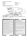
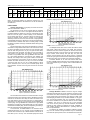
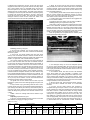
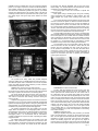
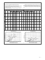
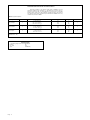
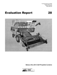
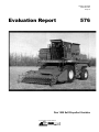
Tested at: Humboldt
ISSN 0383-3445
Group 4c
Evaluation Report
576
Don 1500 Self-Propelled Combine
A Co-operative Program Between
ALBERTA
FARM
MACHINERY
RESEARCH
CENTRE
PAMI
PRAIRIE AGRICULTURAL MACHINERY INSTITUTE
DON 1500 SELF-PROPELLED COMBINE
MANUFACTURER:
Tractoroexport
Rostselmash
Rostov-On-Don, U.S.S.R.
RETAIL PRICE:
$109,890.00 (March, 1988, f.o.b. Humboldt, Sask., with a 11.5 ft
(3.5 m) pickup on a 13 ft (4.0 m) pickup header, feeder reverser,
loss monitor, heater, a/c, and straw chopper).
DISTRIBUTOR:
Belarus Equipment of Canada Ltd.
225 - 6th Avenue East,
P.O. Box 3665
Regina, Saskatchewan
S4P 3N8
Phone: (306) 757-5617
FIGURE 1. Don 1500: (1) Cylinder, (2) Concave, (3) Rear Beater, (4) Straw Walkers,
(5) Cleaning Shoe, (6) Tailings Return.
SUMMARY AND CONCLUSIONS
Capacity: In the capacity tests, the MOG feedrate* at 3%
total grain loss in Harrington barley was 500 lb/min (13.6 t/h).
In wheat crops, combine capacity was 625 lb/min (17.1 t/h) in
Columbus wheat and 800 lb/min (21.8 t/h) in Katepwa wheat.
In barley, the Don 1500 had approximately 1.35 times the
capacity of the PAMI Reference II combine when compared at
3% total grain loss. In wheat, at 3% total loss, the capacity of the
Don 1500 was about 1.15 times that of the Reference II combine
in Columbus and 1.25 times in Katepwa.
Quality of Work: Pickup performance was good. In most
crops, it picked cleanly and although it fed the crop quite high
on the table auger, no problems were experienced. Feeding was
very good. The table auger, front feeder drum and feeder chain
were aggressive and seldom plugged.
The stone trap provided good stone protection. Some larger
stones and roots were stopped between the table auger and front
feeding drum. Most stones and roots were trapped in the pocket
in front of the cylinder. Stones, which went through the combine,
caused minor damage to the concave.
Threshing was good. To obtain acceptable unthreshed loss
in hard-to-thresh wheat crops, the concave clearance had to
be reduced from the factory’s suggested settings, and concave
blanks were needed. Grain damage was low in all crops.
Separation of grain from straw was good. Straw walker loss
was low for canola and flax, but either limited capacity or was a
major part of the total loss in wheat and barley crops. Cleaning
shoe performance was good. The shoe could be set to achieve
acceptable loss in all crops at reasonable feedrates. In some
crops, the clean grain sample contained foreign material, which
the shoe should have been able to remove.
Grain handling was good. The 185 Imperial bushel (6.7 m³)
*MOG feedrate (Material-Other-than-Grain Feedrate) is the mass of straw and chaff
passing through the combine per unit of time.
Page
2
grain tank filled evenly. The unloader, although hydraulically
positioned, unloaded only in the fully extended position. A full
grain tank of wheat unloaded in about 150 seconds. The tank
vibrator aided in unloading damp grain.
No straw spreading device was supplied.
Ease of Operation and Adjustment: Operator comfort was
fair. The cab was quiet and relatively dust free. The air conditioner
provided adequate cooling. A heater was supplied after the harvest
season. The seat and steering column were adjustable, but did
not provide a convenient operating position for some operators.
The operator had a clear view forward, to the left, and along the
left side, but visibility along the right side was restricted. View
of the incoming windrow was partially blocked by the steering
wheel.
Instrumentation was good. All important functions were
monitored with a combination of gauges, a digital display,
warning lights and audio alarm. The digital display could not be
read in direct sunlight. The controls were fair. Some controls were
inconveniently placed and some did not respond adequately.
Loss monitor performance was good. Both the shoe and straw
walker loss were monitored. The lowest monitor sensitivity was
too high for most crops and monitor overload activated annoying
warnings.
Lighting for nighttime harvesting was good. The Don 1500
was not equipped with amber four-way flashers.
Handling was good. The steering was slower than most North
American combines. The combine was stable in the field and
when transporting.
Ease of adjusting combine components was good, and the
ease of setting the components to suit crop conditions was also
good.
The ease of unplugging was very good. The feeder had a
unique reverser, which worked well. The cylinder did not plug.
Ease of cleaning was good. The grain tank was easy to clean, but
the body collected a lot of chaff. Access doors were provided for
cleaning inside. The sieves were difficult and time consuming to
remove.
Ease of lubrication was very good. The most frequent interval
was 60 hours. Ease of routine maintenance was good.
Engine and Fuel Consumption: The engine started poorly at
temperatures below 50° F (10° C). Ether was required. Once the
engine was warm, it started well, ran well and had ample power
for all crops and conditions encountered.
Average fuel consumption was about 4.4 gal/h (20 L/h). Oil
consumption was insignificant.
Operator Safety: The combine safety decals were not yet
converted to English. Most of the machine was well shielded.
Caution was required when making adjustments on the combine.
Operator’s Manual: No English operator’s manual was
provided.
Mechanical History: Only a few very minor failures
occurred.
RECOMMENDATIONS
It is recommended that the manufacturer consider:
1. Modifications to have initial front concave clearance set so
that a minimum clearance of 3/8 in (9.5 mm) can be obtained,
and that optional concave blanks be provided.
2. Modifications to ensure cleaning sieve openings are uniform.
3. Modifications to increase unloading auger clearance.
4. Providing a straw chopper and/or straw spreader as optional
equipment.
5. Modifications to improve seat comfort.
6. Providing a mirror for the right side that is easy to see and has
a wide field of view.
7. Modifications to improve fuel gauge accuracy, digital display
visibility and to identify the normal operating range for the
pressure and temperature gauges.
8. Modifications to provide faster separator disengagement.
9. Modifications to improve the ease of operating the header
engagement lever.
10. Modifications to permit faster header drop rate.
11. Modifications to improve the ease of shifting.
12. Modifications to improve the convenience and ease of
operating the hydrostatic ground speed control lever.
13. Modifications to provide more adjustment to decrease loss
monitor sensitivity.
14. Installing a light in the grain tank.
15. Providing amber flashing lights that meet the North American
standards (ASAE S279.8, SAE J974).
16. Modifications to provide smooth fast turning.
17. Modifications to permit safe convenient sampling of the return
tailings.
18. Modifications to provide unobstructed shoe discharge.
19. Modifications to permit quick, easy chaffer sieve removal.
20. Providing warning decals with appropriate symbols and
English instructions.
21. Modifications to eliminate the possibility of an operator
mistaking the pedal to the left of the steering column for a
clutch.
Senior Engineer: J.D. Wassermann
Project Manager: L.G. Hill
THE MANUFACTURER STATES THAT
With regard to recommendation number:
1. The initial concave adjustment will be modified to obtain
minimal concave clearance of 0.51 in (13 mm) at the front
and 0.08 in (2 mm) at the rear. Four concave blanks will be
supplied as standard equipment.
2. Cleaning sieve uniformity will be improved.
3. As PAMI indicated, the clearance is adequate for most farm
trucks, but we will consider increasing auger clearance on
future designs.
4. A straw chopper capable of chopping, or chopping and
spreading the straw will be provided as optional equipment.
5. The seat will be replaced with a more comfortable model on
future production machines.
6. Modifications will be made to the right mirror to improve the
visibility and increase the field of view.
7. Changes have been made to improve fuel gauge accuracy.
Modifications to improve display visibility and identification of
normal operating ranges on gauges are under consideration.
8. Modifications will be made to provide faster separator
disengagement.
9. Changes to header engagement will be considered for future
design.
10. Modifications will be made to increase the header drop rate.
11. Modifications will be made to improve the ease of shifting.
12. Modifications will be made to improve the ease of operation
and control of the hydrostatic ground speed control.
13. Changes have been made to make the monitor sensitivity
more suitable and the alarm sound level has been made
adjustable.
14. Installation of a light in the grain tank will be considered.
15. Installation of flashing amber lights will be considered.
16. This recommendation will be investigated.
17. Methods for sampling the return tailings are being investigated.
18. Machines shipped to North America will have the chaff “kicker”
removed to provide unobstructed shoe discharge.
19. Changes to improve the ease of chaffer sieve removal and
installation are being investigated.
20. English decals will be installed.
21. If the recommended procedure is used, the combine can
be operated safely; however, this recommendation will be
investigated.
GENERAL DESCRIPTION
The Don 1500 is a self-propelled combine. It has a single
transverse mounted cylinder, concave, rear beater, straw walkers
and a cleaning shoe. The open design cylinder has 10 rasp bars with
the ribs on alternate bars having the opposite angle. A bar and wire
concave is matched to the cylinder. There are four, stepped, closed
bottom, straw walkers. The cleaning fan is a six blade paddle fan.
The chaffer sieve and cleaning sieve are both adjustable lip sieves
which move in opposed motion. The tailings sieve has adjustable
slats and adjustable “saw tooth” louvres (FIGURE 2). The combine
is equipped with an independent rethresher (FIGURE 3).
FIGURE 2. Tailings Sieves.
Crop is fed from the feeder to the cylinder where, upon contact,
threshing begins. The crop is pulled between the cylinder and
concave where further threshing takes place and grain separation
begins. The crop is stripped away from the cylinder by a beater and
directed onto the straw walkers for further separation. The separated
material is carried to the shoe by an oscillating grain pan. The grain
is cleaned by a combination of pneumatic and sieving action. Tailings
are delivered to a rethresher and then back onto the grain pan.
The test combine has a 217 hp (162 kW) turbo charged six
cylinder diesel engine. It is equipped with a 13 ft (4.0 m) pickup
header fitted with an 11.5 ft (3.5 m) two roller, draper pickup. The
pickup consists of a single full width draper with spring steel teeth.
The Don 1500 has an operator’s cab with air conditioning.
It has power steering, hydraulic wheel brakes and a three speed
transmission with hydrostatic ground drive.
FIGURE 3. Rethresher.
Page
3
RESULTS AND DISCUSSION
FIGURE 3. Rethresher.
The separator drive is controlled by a manually operated
hydraulic valve, which activates a hydraulically actuated belt
tightener. The header drive is controlled by a manually operated
mechanical belt tightener. Header height is controlled by a manually
operated hydraulic valve. Unloading auger swing, unloading auger
drive, and cylinder speed are controlled by electro-hydraulic valves.
Concave clearance is adjustable from within the cab. Cleaning fan
speed and sieve adjustments are made along the left side of the
machine. Important component speeds and harvest functions are
displayed on electronic monitors.
Detailed specifications are given in APPENDIX I.
SCOPE OF TEST
The main purpose of the test was to determine the functional
performance of the Don 1500. Measurements and observations
were made to evaluate the Don 1500 for rate of work, quality of
work, ease of operation and adjustment, engine performance,
operator safety and the suitability of the operator’s manual. Although
extended durability testing was not done, the mechanical failures,
which occurred during the test were recorded.
The Don 1500 was operated for 106 hours while harvesting
about 825 ac (334 ha) of various crops. In addition, capacity tests
were conducted in two wheat crops and one barley crop.
The operating conditions for the season are shown in TABLES
1 and 2.
TABLE 1. Operating Conditions
Crop
Variety
bu/ac
t/ha
ft
Barley
Herrington
65-75
3.54.0
18
5.5
Canola
Tobin
17-30
1.01.7
20, 26
6.1,
7.9
Flax
Norlin
14-22
Raja
16-20
0.91.4
1.01.3
18,
30,
42
25
5.5,
9.1,
12.8
7.6
Columbus
Katepwa
35
14-39
2.4
0.92.6
25
7.6
9.1,
15.2
Wheat
Yield Range
Width of Cut
30, 50
Total
Sep.
Hours
Field Area
Crop
Harvested
ac
ha
bu
t
34.5
150
60.7
10600
231.3
9.0
70
28.3
1765
40.1
21.5
165
66.8
2580
65.7
6.5
65
26.3
1130
28.7
0.5
5
2.0
175
4.8
m
34.0
370
149.7
7465
203.6
106.0
825
333.8
23715
574.2
TABLE 2. Operation in Stony Conditions
Field Conditions
Hours
Field Area
ac
ha
Stone Free
38
178
72.0
Occasional Stones
55
532
215.3
Moderately Stony
13
115
46.5
Total
106
625
333.8
Page
4
TERMINOLOGY
MOG, MOG Feedrate, Grain Feedrate, MOG/G Ratio and
Total Feedrate: A combine’s performance is affected mainly by the
amount of straw and chaff it is processing and the amount of grain
or seed it is processing. The straw, chaff, and plant material other
than the grain or seed is called MOG, which is an abbreviation for
“Material-Other-than-Grain”. The quantity of MOG being processed
per unit of time is called “MOG Feedrate”. Similarly, the amount of
grain being processed per unit of time is the “Grain Feedrate”.
The MOG/G ratio, which is the MOG Feedrate divided by the
Grain Feedrate, indicates how difficult a crop is to separate. For
example, MOG/G ratios for prairie wheat crops may vary from 0.5
to 1.5. In a crop with 0.5 MOG/G ratio, the combine has to handle
50 lbs (22.7 kg) of straw for every 100 lbs (45.4 kg) of grain harvested.
However, in a crop with a 1.5 MOG/G ratio for a similar 100 lbs
(45.4 kg) of grain harvested, the combine now has to handle
150 lbs (68.1 kg) of straw –- 3 times as much. Therefore, the higher
the MOG/G ratio, the more difficult it is to separate the grain.
Total feedrate is the sum of MOG and grain feedrates. This
gives an indication of the total amount of material being processed.
This total feedrate is often useful to confirm the effects of extreme
MOG/G ratios on combine performance.
Grain Loss, Grain Damage, Dockage and Foreign Material:
Grain loss from a combine can be of two main types: Unthreshed
Loss, consisting of grain left in the head and discharged with the
straw and chaff, or Separator Loss which is free (threshed) grain
discharged with the straw and chaff. Separator Loss can be further
defined as Shoe Loss and Walker (or Rotor) Loss depending where
it came from. Loss is expressed as a percentage of the total amount
of grain being processed.
Damaged or cracked grain is also a form of grain loss. In this
report, the cracked grain is determined by comparing the weight of
the actual damaged kernels to the entire weight of a sample taken
from the grain tank.
Dockage is determined by standard Canadian Grain
Commission methods. Dockage consists of large foreign particles
and of smaller particles that pass through a screen specified for
that crop. It is expressed as a percentage of the weight of the total
sample taken.
Foreign material consists of the large particles in the sample,
which will not pass through the dockage screens.
Capacity: Combine capacity is the maximum rate at which a
combine, adjusted for optimum performance, can process crop at a
certain total loss level. PAMI expresses capacity in terms of MOG
Feedrate at 3% total loss. Although MOG Feedrate is not as easily
visualized as Grain Feedrate, it provides a much more consistent
basis for comparison. A combine’s ability to process MOG is relatively
consistent even if MOG/G ratios vary widely. Three percent total
loss is widely accepted in North America as an average loss rate
that provides an optimum trade-off between work accomplished and
grain loss. This may not be true for all combines nor does it mean
that they cannot be compared at other loss levels.
Reference Combine: It is well recognized that a combine’s
capacity may vary greatly due to differences in crop and weather
conditions. These differences make it impossible to directly
compare combines not tested in the same conditions. For this
reason, PAMI uses a reference combine. The reference combine is
simply one combine that is tested along with each combine being
evaluated. Since the test conditions are similar, each test combine
can be compared directly to the reference combine to determine
a relative capacity or “capacity ratio”. This capacity ratio can be
used to indirectly compare combines tested in different years and
under different conditions. As well, the reference combine is useful
for showing how crop conditions affect capacity. For example, if the
reference combine’s capacity is higher than usual, then the capacity
of the combine being evaluated will also be higher than normally
expected.
For 10 years, PAMI had used the same reference combine.
However, capacity differences between the reference combine and
some of the combines tested became so great that it was difficult
to test the reference combine in the conditions suitable for the
evaluation combines. PAMI changed its reference combine to better
handle these conditions. The new reference combine is a larger
conventional combine that was tested in 1984 (see PAMI report
TABLE 3. Capacity of the Don 1500 at a Total Loss of 3% of Yield
Crop Conditions
Width of Cut
Crop Yield
Results
Crop
Variety
ft
m
bu/ac
t/ha
Straw %
Moisture Content
Grain %
MOG/G
lb/min
MOG Feedrate
t/h
bu/h
t/h
lb/min
t/h
Grain
Cracks
%
Dockage
%
Foreign
Material
Loss
Curve
Barley
Wheat
Wheat
Harrington
Columbus
Katepwa
20
25
60
6.1
7.6
18.3
72
37
35
3.88
2.49
2.36
7.6
5.6
12.4
10.8
12.8
16.1
1.01
1.26
1.15
500
625
800
13.6
17.1
21.6
620
495
695
13.5
13.5
19.0
995
1120
1495
27.1
30.6
40.8
1.0
1.5
1.0
1.5
3.0
1.5
0.5
0.8
0.3
4
5
6
#426). To distinguish between the reference combines, the new
reference will be referred to as Reference II and the old reference
as Reference I.
RATE OF WORK
Capacity Test Results: The capacity test results for the Don
1500 are summarized in TABLE 3.
The performance curves for the capacity tests are presented
in FIGURES 4 to 6. The curves in each figure indicate the effect of
increased feedrate on walker loss, shoe loss, unthreshed loss and
total loss. From the graphs, combine capacity can be determined
for loss levels other than 3%. The rate at which loss changes with
respect to feedrate shows where the combine can be operated
effectively. Portions of loss curves, which are “flat” or slope gradually
indicate stable performance. Where the curves hook upward sharply,
small increases in feedrate cause loss to increase greatly. It would
be difficult to operate in this range of feedrates without having widely
varying loss.
The Harrington barley crop used for the test was from a uniform
stand laid in a single well formed windrow. The windrow was nearly
as wide as the feeder on the Don 1500. The crop was mature and
both the straw and grain were very dry. The grain threshed easily
and the awns broke off readily. The straw was long and break-up
was average. The yield was a good average, but the long straw
resulted in a high MOG/G ratio. The high MOG/G ratio meant that
for a given MOG feedrate the accompanying grain feedrate was
relatively low. Settings used were typical of those recommended
by the manufacturer. In this barley crop at 3% total loss, the MOG
feedrate was about 500 lb/min (13.6 t/h). The curves in FIGURE
4 show that loss was very Low up to MOG feedrates of about
350 to 400 lb/min (9.6 to 10.9 t/h). Loss increased rapidly above
those feedrates. The main source of grain loss was over the straw
walkers.
Grain Feedrate
Total Feedrate
feedrates. Capacity was limited by straw walker loss.
FIGURE 5. Grain Loss in Columbus Wheat.
The Katepwa wheat came from a uniform stand laid in double
well formed, side-by-side windrows. The heads were uniformly
distributed over each windrow. Together the windrows were much
wider than the feeder on the Don 1500. The grain and straw were
tough; however, straw break-up was quite high. The yield was
average and the MOG/G ratio was about average. In Katepwa
wheat, the higher grain and straw moisture enabled more aggressive
threshing to be used, thus providing more aggressive separation.
The MOG feedrate at 3% total loss reached 800 lb/min
(21.8 t/h). FIGURE 6 shows that grain loss increased gradually over
most of the feedrate range. At capacity, shoe and straw walker loss
were equal.
FIGURE 6. Grain Loss in Katepwa Wheat.
FIGURE 4. Grain Loss in Harrington Barley.
The Columbus wheat came from a uniform stand laid in a single
well formed windrow. The heads were evenly distributed across the
windrow and the windrow was nearly as wide as the feeder of the
Don 1500. Both the grain and straw were very dry. Straw break-up
was average. The yield was a good average, but the MOG/G ratio
was fairly high. The high MOG/G ratio meant that for a given MOG
feedrate the accompanying grain feedrate was Low. The Columbus
wheat threshed relatively easy, but was susceptible to grain damage,
thus less aggressive threshing settings were used.
At 3% total loss, the MOG feedrate in the Columbus wheat
was about 625 Lb/min (17.1 t/h). The loss curves in FIGURE 5 show
that total loss remained low up to MOG feedrates of about 500 to
550 Lb/min (13.6 to 15.0 t/h). Loss increased rapidly above those
Average Workrates: TABLE 4 shows the range of average
workrates achieved during day-to-day operation in the various crops
encountered. The table is intended to give a reasonable indication
of the average rates most operators could expect to obtain, while
acknowledging the effects of crop and field variables. For any given
crop, the average workrates may vary considerably. Although a
few common variables such as yield and width of cut are included
in TABLE 4, they are by no means the only or most important
ones. There are many other crop and field conditions which affect
workrate; as well, operating at different loss levels, availability of
grain handling equipment and differences in operating habits can
have an important effect.
The effect of the variables, as indicated in TABLE 4, explains
why even the maximum average workrates may be considerably
lower than the capacity results, which are instantaneous workrates.
Page
5
Clearly TABLE 4 should not be used to compare performance
of combines. The factors affecting average workrates are simply
too numerous and too variable to be duplicated for each combine
tested.
TABLE 4. Field Workrates
Crop
Range
bu/h
t/h
ac/h
ha/h
ft
m
bu/ac
t/ha
Barley
High
Low
Avg.
350
275
310
7.6
6.0
6.8
5.4
3.9
4.4
2.2
1.6
1.8
18
18
5.5
5.5
65
70
71
3.5
3.8
3.8
Harrington
Harrington
Canola
High
Low
Avg.
205
145
190
4.7
3.3
4.3
7.3
8.1
7.6
3.0
3.3
3.1
26
20
7.9
6.1
28
18
25
1.6
1.0
1.4
Tobin
Tobin
Flax
High
Low
Avg.
185
65
133
4.7
1.7
3.4
9.3
3.0
8.2
3.8
1.2
3.3
30
18
9.1
5.5
20
22
16
1.3
1.4
1.0
Norlin
Norlin
High
Low
Avg.
275
170
220
7.5
4.6
6.0
7.1
12.1
10.8
2.9
4.9
4.4
30
50
9.1
15.2
39
14
20
2.6
0.9
1.4
Katepwa
Katepwa
Wheat
Grain
Feedrate
Area Rate
Width of
Cut
Yield
Variety
Comparing Combine Capacities: The capacity of combines
tested in different years or in different crop conditions should be
compared only by using the PAMI reference combines. Capacity
ratios comparing the test combine to the reference combine are
given in the following section. For older reports where the ratio is not
given, a ratio can be calculated by dividing the MOG feedrate listed
in the capacity table by the corresponding MOG feedrate of the
reference combine listed in APPENDIX II for that particular crop.
Once capacity ratios for different evaluation combines have
been determined for comparable crops, they can be used to
approximate capacity differences. For example, if one combine has
a capacity ratio of 1.2 times the reference combine and another
combine has a capacity ratio of 2.0 times the reference combine,
then the second combine is about 67% larger ((2.0 - 1.2) / 1.2 x
100 = 67%). An evaluation combine can also be compared to the
reference combine at losses other than 3%. The total loss curves
for the test combine and reference combine are shown in the graphs
in the following section. The shaded bands around the curves
represent 95% confidence belts. Where the bands overlap, very
little difference in capacity exists; where the bands do not overlap, a
significant difference can be noticed.
PAMI recognizes that the change to the Reference II combine
may make it difficult to compare test machines, which were compared
to Reference I. To determine a relative size, it is necessary to use a
ratio of the two reference combines. Tests indicate that Reference
II had about 1.50 to 1.60 times the capacity of Reference I in wheat
and about 1.40 to 1.50 times Reference I’s capacity in barley.
Capacity Compared to Reference Combine: At 3% total
grain loss, the capacity of the Don 1500 was greater than that of
the PAMI Reference II combine in both wheat and barley. At the
3% total loss level, the Don 1500 had about 1.35 times the capacity
of Reference II in barley and about 1.15 times and 1.25 times the
Reference II’s capacity in Columbus and Katepwa respectively.
FIGURES 7 to 9 compare the total losses of the Don 1500
and the Reference II combine. The curves show that there was a
significant difference between the combines at the 3% loss level.
However, at Low loss the difference was much smaller.
FIGURE 7. Total Grain Loss in Harrington Barley.
Page
6
FIGURE 8. Total Grain Loss in Columbus Wheat.
FIGURE 9. Total Grain Loss in Katepwa Wheat.
QUALITY OF WORK
Picking: Pickup performance was good.
The pickup was usually operated at about a 20° angle to
the ground. The gauge wheels were adjusted so the teeth just
touched the ground. The draper speed was set just slightly faster
than ground speed. With these settings, reasonably well supported
windrows were picked cleanly at speeds up to 6 mph (9.7 km/h). In
poorly supported windrows, pickup speed was increased. In these
conditions, pickup loss often increased noticeably at ground speeds
over 3.5 mph (5.6 km/h). Even in tangled crops or tall stubble, the
single draper was aggressive and did not stall. The single draper,
which overlapped the table, prevented grain loss once the crop was
on the picking draper. The pickup did pick stones and roots quite
readily due to the Low picking angle and spring teeth.
Pickup angle was important for smooth delivery of crop to the
table auger. At pickup angles over 20°, the crop delivery height to the
table auger increased as pickup and ground speed were increased.
In most crops, the windguard deflected the crop under the table
auger. However, in canola the windguard had to be removed as it
restricted crop flow to the table auger.
Feeding: Feeding was very good.
As with all conventional combines, to fully utilize the threshing
and separating ability at the cylinder and concave, it was necessary
to feed windrows that were at least as wide as the cylinder and
concave and that had the heads evenly distributed across the width.
In narrower windrows or windrows with the heads concentrated in
one area, it was best to center the windrow or heads on the feeder
opening.
The large table auger was aggressive and provided a smooth
flow of crop under the auger to a second feeding drum, which in turn
fed the crop to the feeder chain.
The table auger seldom plugged, but did wrap in tough flax
straw. No adjustment prevented the wrapping. A slower table auger
speed may have reduced the tendency to wrap. However, wrapping
was not severe enough to stop harvesting.
The second feeding Drum and feeder chain were aggressive
and did not plug. Stone Protection: Stone protection was good.
The stone trap, located in front of the concave, was effective
in collecting most stones and roots, which were driven into the
pocket upon contact with the cylinder. Objects up to 6 in (152 mm)
In barley, the concave was set using the factory adjustment.
This provided much wider front clearance than used on most North
American combines. Typical of conventional combines, straw walker
loss limited the Don 1500’s capacity. Closer concave clearance may
have decreased walker loss.
In easy threshing wheat, walker loss also limited capacity even
after the concave linkage was readjusted. However, in hard-tothresh wheat, where more aggressive cylinder speeds were used,
straw walker and shoe loss were similar at capacity.
In canola and flax crops, straw walker loss was negligible even
with concave blanks installed.
The settings used in the various crops are shown in TABLE 5.
Cleaning: Cleaning shoe performance was good.
Shoe loading uniformity was hard to determine because of the
effects of the “chaff kicker” (FIGURE 11) located behind the chaffer.
Material off the shoe built up on the trough until the rotating sweep
“kicked” the chaff off in a bunch. Shoe loading could not be checked
using the “kill stall” method since the separator could not be stopped
quickly nor disengaged after the combine had been stopped.
Shoe loss generally was acceptable and the uniformity of the
loss suggested that loading was even.
in diameter were emptied from the trap. Larger roots and stones
stopped the feeder when they jammed under the secondary feeder
drum. These objects broke one retractable finger and bent the
feed assist plate on the secondary feeder drum. Both were minor
damages and did not affect feeding. The feeder chain slats were
not damaged. The stone trap was most effective if emptied regularly
to prevent grain and dirt from hardening in the “trap”. Some small
stones did go through the combine. The cylinder was not seriously
damaged. However, several concave wires were broken, bars
scored and some of the bars were bent (FIGURE 10).
FIGURE 10. Concave Damage.
Threshing: Threshing was good.
In all crops and conditions, the crop fed smoothly into the
cylinder and concave area. There was no evidence of backfeeding
around the cylinder.
In most crops, the cylinder speeds were lower than those
used by most conventional combines. However, because the Don
1500 had a larger diameter cylinder, the speed of the rasp bars was
similar to, or higher than, that of smaller diameter cylinders.
The concave clearances used were much larger, especially at
the front, than those used with most other conventional combines.
In most crops, the factory recommended clearance was suitable. In
wheat and flax, the clearance at the front was reduced to the limit
of the linkage adjustment. This reduced the front clearance from 3/4
to 1/2 in (19 to 12 mm). In addition, in hard-to-thresh wheat and in
flax it was necessary to blank the first four spaces in the concave
to do an acceptable job of threshing. When adjusted accordingly,
unthreshed loss was acceptable. However, even less clearance may
have provided adequate threshing without the use of blanks. It is
recommended that the manufacturer consider modifications to have
initial front concave clearance set so that a minimum clearance of
3/8 in (9.5 mm) can be obtained. It is also recommended that the
manufacturer provide optional concave blanks.
The tighter front concave clearance did not hinder crop flow
between the cylinder and concave although slightly more power was
required.
In easy-to-thresh crops, grain damage was low. Even in hardto-thresh wheat, when using very aggressive threshing adjustments,
grain damage was relatively low. This may have been due partly to
crop entry angle to the cylinder, the wide front concave clearance
and/or the tailings being returned to the rethresher rather than the
cylinder.
TABLE 5 shows the settings PAMI used for different crops
encountered.
Separating: Separation was good.
In all crops, the material flowed smoothly over the concave and
straw walkers. No plugging or bridging occurred.
FIGURE 11. “Chaff Kicker”.
In the Harrington barley, the shoe had adequate capacity
for the Don 1500’s separating ability. Shoe loss was low over the
practical operating range. In barley crops, which have a low MOG/G
ratio, higher grain feedrates would be obtained and shoe loss may
become more significant.
In the Columbus wheat, shoe loss was low at the feedrates
where straw walker loss was acceptable. In Katepwa, more
aggressive threshing and separating kept straw walker loss lower,
which enabled higher feedrates to be reached. However, these
settings increased shoe loading considerably and shoe loss became
a significant part of the total loss. Even though shoe loss increased
at higher feedrates, it did not become erratic.
In flax and canola crops, shoe loss limited capacity. However,
the shoe was able to maintain loss below 1% at reasonable
feedrates.
In all crops, the Don 1500’s cleaning shoe produced an
acceptable clean grain sample. However, in most crops there was
foreign material in the clean grain sample that the shoe should have
been able to remove. In wheat and oil seeds, the foreign material
in the sample was probably due to the uneven openings of the
cleaning sieve. Lip openings varied as much as 1/8 in (3 mm). The
large difference in openings meant that when the closer sections
were set appropriately, other spots on the sieve had openings large
enough to let part heads and other large particles fall through. It
is recommended that the manufacturer consider modifications
TABLE 5. Crop Settings
Crop
Cylinder
Concave Clearance
Front
Barley
Canola
Flax
Wheat
Sieve Openings
Rear
Chaffer
Fan Speed
Tailings
Cleaning
rpm
in
mm
in
mm
in
mm
in
mm
in
mm
rpm
650-700
550
890
890
5/8 - 3/4
1
1/2 - 5/8
1/2
15 - 19
25
12 - 16
12
1/8 - 3/16
3/8
1/8 - 3/16
1/16
3-5
10
3-5
1-2
5./8 - 7/8
13/16 - 7/8
1/2 - 5/8
8/8 - 7/8
16 - 22
20 - 22
13 - 16
16 - 22
3/8 - 5/8
0 - 3/8
0 - 3/8
5/8 - 7/8
10 - 16
0 - 10
0 - 10
15 - 22
1/4 - 5./16
1/16
1/16
1/8 - 3/16
6-8
1-2
1-2
3-5
870 - 890
580 - 590
640 - 660
860 - 900
Page
7
to ensure cleaning sieve openings are uniform. In barley, foreign
material was usually not a problem. However, when foreign material
did become a problem, it was found that chaff had accumulated
on the cleaning fan intake screen (FIGURE 12). Cleaning off the
chaff improved the sample. Very dry straw, leaves in the stubble and
thistles promoted the plugging.
FIGURE 12. Chaff Blocking the Cleaning Fan Intake Screen.
Clean Grain Handling: Grain handling was good.
With the grain tank cover open, the tank filled evenly in all
crops. The corners did not fill completely. A full tank of dry wheat
contained about 185 bu (6.7 m3). Full bin sensors were supplied.
When set in the upper position, the warning came on with the tank
80 to 85% full. The warning consisted of a light in the cab and the
rotating beacon that signalled the grain hauler. If overfilled, grain
spilled over the front of the grain tank.
Although the unloading auger was hydraulically positioned,
safety switches ensured that the auger had to be swung out
completely before unloading.
The unloading auger clearance was marginal. The auger
cleared most truck boxes (FIGURE 13), but did not have enough
clearance to unload grain into the center of grain trailers. It is
recommended that the manufacturer consider modifications to
increase unloading auger clearance.
generally broken more than from other conventional combines. It
was still suitable for baling.
EASE OF OPERATION AND ADJUSTMENT
Operator Comfort: Operator comfort was fair. The Don 1500
was equipped with an operator’s cab positioned ahead of the
grain tank and slightly left of center. The cab was fairly accessible.
However, changing hand hold from the ladder to the platform railing
was inconvenient. The cab was quiet and relatively dust proof.
The air conditioner provided comfortable cab temperature in hot
weather. The cab heater did not arrive until after harvest. The heater
was capable of maintaining comfortable cab temperatures in much
colder weather than would be experienced during harvest. The
heater did lack a temperature control.
The steering wheel was equipped with tilt and telescoping
adjustments. Although adequate, increased tilt would have been
desirable. The seat was adjustable, but in the rear-most position,
the window opener protruded over the top of the seat and could
be bumped by the operator’s back. Also, the vinyl seat was very
hot and uncomfortable. It is recommended that the manufacturer
consider modifications to improve seat comfort.
The operator had a clear view forward, to the left and rearward
along the left side. Visibility to the right was restricted. The mirror on
the left provided visibility along the left side. However, the mirror on
the right was very difficult to see and provided a very limited field of
view. It is recommended that the manufacturer consider providing
a mirror for the right side that is easy to see and has a wide field of
view.
View of the incoming windrow was partially blocked by the
steering wheel. To see the table auger, it was necessary to slide
the seat forward and lean forward slightly (FIGURE 14). This was
comfortable, but made access to some controls, especially the
header height control lever, less convenient.
FIGURE 14. View of Header.
FIGURE 13. Marginal Unloading Auger Clearance.
The unloading auger discharged the grain in a compact stream,
unloading a full tank of dry wheat in about 150 seconds. Adjusting
the regulating flaps over the tank auger from the mid-position to the
fully raised position increased the unloading rate, which decreased
the unloading time to about 130 seconds. However, in damp flax,
the unloader drive was unable to start when the regulating flaps
were fully raised. The grain tank vibrators aided in unloading damp
grain.
Straw Spreading: The Don 1500 was supplied without a straw
chopper or straw spreader. It is recommended that the manufacturer
consider providing a straw chopper and/or straw spreader as
optional equipment.
The straw, after being combined by the Don 1500, was
Page
8
Grain entering the grain tank and the grain level were visible
through the rear cab window and window in the grain tank. The
operator had a clear view of the unloading auger when unloading.
Instrumentation: Instrumentation was good.
The instruments were located to the right of the operator and
on a ceiling console (FIGURES 15 and 16). The console to the
right had gauges for engine oil pressure, battery charge, coolant
temperature, hydrostatic oil temperature and fuel level. The coolant
and hydrostatic oil temperature shared a common gauge with a
switch to select the desired function. The console also contained
a digital display. This display provided a selective readout for an
electronics system check, ground speed, cylinder speed, fan speed
and engine speed.
Most of these instruments worked well. However, the fuel
gauge was inaccurate and the digital display could not be read
in direct sunlight. As well, the oil pressure, engine coolant and
hydrostatic oil temperature gauges did not have normal and/or
dangerous operating ranges identified. It is recommended that the
manufacturer consider modifications to improve fuel gauge accuracy,
digital display visibility and identifying the normal operating ranges
of the pressure and temperature gauges.
The upper console had three sets of lighted warning symbols
(FIGURE 16) and an audible alarm. One set of warnings indicated
power on, low engine oil pressure, excessive coolant temperature,
straw walkers plugged and full scale grain loss monitor reading.
The second set of indicators signalled a full grain bin, park brake
engaged, and restricted flow in the hydraulic system. The third set
of warning indicators were for speed reduction of the cylinder, grain
pan, tailings auger, clean grain auger, straw walkers, and straw
chopper.
FIGURE 15. Instruments to Right of Operator.
but the drop rate, although adjustable, was too slow even at the
fastest setting. It is recommended that the manufacturer consider
modifications to permit faster header drop rate.
The pickup speed control was convenient to operate and
responded quickly.
Rotor speed change, unloading auger swing and unloading
auger engagement were actuated by rocker switches. The rotor
speed changed very quickly, while unloading auger swing was
slow.
The concave adjusting lever was located to the right of the seat
and was convenient to operate. A clearance indicator showed the
front and rear concave clearance if the concave was adjusted to
factory specifications. However, the indicator was inaccurate after
the concave linkage had been adjusted to suit hard-to-thresh crops.
The Don 1500 also had a pedal that released the concave allowing
the front and rear of the concave to drop away from the cylinder. This
was convenient as it enabled wads to be powered through.
The gear shifting lever had too much “spring” in the linkage and
did not provide a positive feel of engagement. It also took considerable
force to shift gears. On one occasion when the combine was left in
gear and stopped, the transmission could not be shifted to neutral.
The safety switches had to be “shorted” before the combine could
be restarted. It is recommended that the manufacturer consider
modifications to improve the ease of shifting the transmission.
The hydrostatic lever was inconveniently placed. When the
seat was set back, the lever was difficult to reach. With the seat
forward, when the hydrostatic lever was moved into reverse, it
hit the operator’s knee (FIGURE 17). The lever also flexed which
caused poor control. As well, neutral was very hard to locate. It
is recommended that the manufacturer consider modifications to
improve the convenience and ease of operating the hydrostatic
ground speed control lever.
FIGURE 16. Warning Monitors in Ceiling Console.
The symbols were clearly visible and provided adequate
warning for malfunction. The audible alarm was loud and annoying.
The electrical system used a combination of 12 and 24 volt power
supply. The starter and lights were powered by 24 volts, while the
instrumentation operated on 12 volts.
Controls: The controls on the Don 1500 were fair.
Most of the controls were located to the right of the operator,
the rest were on the steering column and to the left of the seat. Most
were easy to operate, but some were inconveniently placed.
The engine throttle lever also shut off the fuel. There was no
indication of where the shut off began or the range of throttle travel.
This made it inconvenient when starting and when slowing the
engine to an idle.
Separator disengagement was slow. The control lever had to be
held back for 10 to 15 seconds until the hydraulically actuated belt
tightener had fully disengaged. Quick or emergency disengagement
was impossible. It is recommended that the manufacturer consider
modifications to provide faster separator disengagement.
The header engagement lever was located to the left and
slightly behind the operator. In the disengaged position, the lever
stood straight up which was a very awkward position for depressing
the lock button. The lever was also inconvenient to return to the
disengaged position. It is recommended that the manufacturer
consider modifications to improve the ease of operating the header
engagement lever.
The header height hydraulic lever was located on the right
console. It was convenient to operate when the seat was in the
rear-most position, but became inconvenient to operate if the seat
was positioned fully forward. The header lift rate was adequate,
FIGURE 17. Interference Between the Hydrostatic Lever and the Operator’s Knee.
Loss Monitor: The loss monitor was fair.
The Don 1500 was equipped with a loss monitor, which had
two sensor pads located near the end of two straw walkers. Two
sensor pads were also located behind the shoe under holes in
the “chaff kicker” trough. The display was located on the front left
corner post of the cab. Grain loss was signalled by two rows of nine
lights. One row represented shoe loss and the other straw walker
loss. The readings were useful if compared to actual loss observed
behind the combine. However, shoe loss sensitivity was too high
even at the lowest sensitivity setting. Very little loss caused full scale
readings. This was annoying since a full scale reading activated
a warning light on the steering column, one on the upper console
and an audible alarm. It is recommended that the manufacturer
consider modifications to provide more adjustment for decreasing
loss monitor sensitivity.
Lighting: Lighting was good.
Lighting for nighttime harvesting was provided by six forward
lights, one light behind the cab and one shining behind the grain
tank. The front lights provided adequate field, windrow and header
illumination. The light on the back of the cab lit the cab platform,
ladder and unloading auger area. This light was very bright for
truckers driving in from behind. A light in the grain tank would have
been useful to illuminate grain entering the tank. It is recommended
Page
9
that the manufacturer consider installing a light in the grain tank.
The gauges were backlit and a recessed light in the right
console provided light for most of the controls. Additional cab lighting
was provided by an interior light on the upper left side of the cab.
The road lights were adequate. The front marker lights, turn
signals, tail lights, brake lights and rotating amber beacon aided in
safe road travel. There were no four way flashers. It is recommended
that the manufacturer consider modifications to provide amber
flashing lights that meet the North American standards (ASAE
S279.8, SAE J974).
Handling: Handling was good.
The Don 1500 was quite maneuverable and picked around
most windrow corners. The wheel brakes helped make sharper
turns.
Steering effort was average, however, more steering wheel
rotation was required for cornering than is common for North
American combines. A “spinner” was provided to aid turning the
steering wheel rapidly. When turning the steering wheel rapidly, the
steering would become stiff. It felt like the power steering could not
keep up to the demand. When the steering wheel was turned slower,
the wheel turned smoothly with much less effort. The problem was
most noticeable on complex corners or when following “zigzag”
windrows. The combine often could not be steered quickly enough
to follow the windrow. It is recommended that the manufacturer
make modifications to provide smooth fast turning.
The gear speed ranges were satisfactory with most harvesting
being done in second gear. The hydrostatic ground drive was
convenient for matching ground speed to crop conditions. It also
made reversing easy on hard-to-pick corners.
The Don 1500 was stable in the field even with a full grain tank.
Normal caution was required when working on hillsides and when
travelling at transport speeds. The combine transported well at a
maximum speed of 14 mph (22 km/h).
Adjustment: Ease of adjusting combine components was
good.
Pickup speed, rotor speed and concave clearance were
adjustable from within the cab. Fan speed and sieve opening
adjustments were located on the side of the machine.
The table auger finger timing and auger and stripper bar clearance
were easily adjusted and, once set to suit crop conditions, did not
have to be readjusted.
Adjusting the concave from within the cab was easy. Adjusting
the concave linkage to change front and rear clearance ratio was
difficult as the drive wheels blocked access to the linkage. Access
ports were provided for gauging front and rear concave clearance.
In hard-to-thresh crops, concave filler blanks had to be installed.
The top of the concave was accessed through the stone trap and
the bottom was accessed by removing the front section of the grain
pan. Although this was inconvenient, it was not difficult.
The fan adjustment was located on the side of the combine
behind the left front wheel. Fan adjustment was inconvenient since
the fan speed display was in the cab. The sieves were adjusted from
the side of the combine (FIGURE 18).
as not to lose the wing nuts, which secured the access panels. A
special wrench was provided for adjusting the cleaning sieve and
chaffer sieve. The first section of the tailings chaffer was adjusted
by an attached lever, which made adjustment quick and easy. The
final section of the tailings chaffer required loosening a locking
mechanism with a wrench and tapping the adjustment open or closed
with a hammer. This adjustment procedure was time consuming and
inconvenient.
Field Setting: Ease of setting the Don 1500 to suit crop
conditions was good. In all crops encountered, it was possible to
achieve acceptable performance.
Threshing was easy to set for in easy-to-thresh crops. However,
in hard-to-thresh crops, the factory’s initial concave settings had to
be readjusted and concave blanks had to be added. Since there was
no straw chopper, it was easy to check for unthreshed loss going
over the straw walkers. The tailings return could not be sampled
to determine how much unthreshed material was on the shoe. It
is recommended that the manufacturer consider modifications to
permit safe convenient sampling of return tailings.
Without the straw chopper, walker loss was easy to check.
Generally, separation was acceptable once reasonable threshing
had been achieved. In canola, leaving the concave blanks in had no
effect on walker loss, and may have helped reduce the shoe loading
by putting more MOG on the straw walkers. In wheat and barley, the
concave blanks noticeably decreased separation.
Setting the shoe was difficult. The major problem was the
“chaff kicker” attachment that discharged the shoe effluent in
bunches. Obtaining a representative sample was very difficult. Also,
the discharge pattern of material from the shoe could not be seen.
It is recommended that the manufacturer consider modifications to
provide unobstructed shoe discharge.
The two stage tailings sieves are different from those in North
America. Since the tailings could not be easily sampled, it was
difficult to determine the effect of their adjustment.
Shoe performance was not only hard to evaluate while
harvesting, but was further complicated since a “kill stall” could not
be used to evaluate the shoe loading. The engine could be stopped,
but the separator drive could not be easily disengaged while the
engine was stopped. Shutting off hot turbo charged engines without
restarting immediately is not advised as this can cause serious
damage.
Unplugging: Ease of unplugging was very good.
The feeder had a unique reverser. A hydraulic cylinder rotated
a ratcheting drive (FIGURE 19). This mechanism could be activated
either from the cab or the ground. The pickup drive had a clutch
to prevent it from being reversed. The reverser backed out most
obstructions. Twice, in very wet flax, the table auger plugged and
would not reverse as the table auger clutch slipped.
FIGURE 19. Header Reverser.
FIGURE 18. Sieve Adjustment.
Removable panels along the side provided access for
adjustment and viewing sieve opening. Caution was required so
Page
10
The cylinder did not plug in these tests. However, the concave
was easily dropped away from the cylinder. This left a clearance of
at least 1.5 in (38 mm) front to back which should allow most wads
to be powered through.
The tailings return plugged several times in damp flax. Opening
the lower door on the elevator and engaging the separator cleared
the blockage.
Machine Cleaning: Ease of cleaning the Don 1500 completely
was good.
The exterior of the combine collected chaff in many places and
would have been difficult to clean without the aid of compressed air
or a portable blower. The grain tank retained very little grain and was
easily accessible. The auger sump held only a small amount of grain
and emptied through a door on the bottom of the auger housing.
The clean grain auger and tailings auger troughs had removable
clean out doors. The sieves were difficult and time consuming to
remove.
The front of the grain pan was removable and doors along the
side of the combine provided access to the rest of the grain pan.
Lubrication: Ease of lubrication was very good.
The combine’s regular lubrication intervals were at every
60 hours and 240 hours. There were 24 fittings to grease at the
60 hour service and 39 more to service at 240 hours. All points were
easily accessible.
Lubrication would have been easier if there were an English
lubrication guide and decals on the combine to help locate the points
and show the service interval.
Engine, hydraulic and hydrostatic oil levels were accessible
for easy checking. Adding hydraulic and hydrostatic oil required the
use of a special pump which adapted to “tap in” fittings on the lines
(FIGURE 20). Oil specifications were not available at the time of
testing.
FIGURE 20. Pump for Adding Hydraulic and Hydrostatic Oil.
The fuel inlet was 9.8 ft (3.0 m) above ground, which made
it very difficult to fill from most gravity fuel tanks. Changing oil and
filters was easy.
Maintenance: Ease of performing routine maintenance was
good.
The Don 1500 used metric hardware. Although tools are
supplied with the combine, most farmers would find that a more
complete set of metric tools is required.
Most chains and belts were easily accessed for checking
and adjusting. The engine was easily accessed for inspection and
service. The radiators swung out and had a coarse core which made
cleaning easy. The engine air filters were easily accessed, but did
not have a restriction indicator.
Slip clutches protected the table auger, feeder, header drive,
clean grain elevator and tailings return. The header was convenient
to remove and had its own stands for support.
The concave could be removed through the front once the stone
trap had been removed and the securing bolts and pins removed.
The concave could be reversed as it is symmetrical.
Sieve removal was inconvenient. The “chaff kicker” trough
had to be removed. The entire shaker frame must be removed in
order to get the chaffer out. Both the chaffer and cleaning sieves are
much heavier than similarly sized sieves found in North American
machines. Installation takes three people. It is recommended that
the manufacturer consider modifications to permit quick, easy
chaffer sieve removal.
to be used. The engine started at temperatures down to 23°F (-5°C)
when ether was used. It was difficult for one person to spray ether
into the air intake and start the combine. It is recommended that the
manufacturer consider supplying optional equipment to provide a
convenient aid for cold weather starting.
Once started, the engine ran well. The engine had ample power
for all crops and conditions encountered. Average fuel consumption
while harvesting was about 4.4 gal/h (20 L/h). Oil consumption was
insignificant.
OPERATOR SAFETY
No operator’s manual was available to indicate safety
precautions. As well, there were no English decals or signs that
indicated unsafe areas. It is recommended that the manufacturer
consider providing warning decals with appropriate symbols and
English instructions.
Moving parts were well shielded. Most shields that required
frequent removal were hinged and had locking mechanisms to hold
them open.
Generally, working around the combine was safe if accepted
safety practices were followed. The operator had to be aware of
certain combine behaviour, which required extra caution. The
Don 1500’s ignition key could not be removed. To protect against
someone starting the combine, the cab door had to be locked.
The Don 1500 had a foot operated pedal located to the left of the
steering column. This aided transmission shifting, but had no effect
on combine travel. Many operators familiar with clutch equipped
machines may in a panic situation step on this pedal expecting
behavior of a clutch. This could create a serious safety problem.
It is recommended that the manufacturer consider modifications to
eliminate the possibility of an operator mistaking the pedal to the left
of the steering column for a clutch pedal.
The neutral position between forward and reverse of the
hydrostatic ground speed control was hard to locate. Often since
the exact neutral was not located, the combine would “creep” either
forward or backward. This made it essential that the transmission be
shifted to neutral and the park brake set before leaving the cab.
A header lift cylinder safety stop was provided and should be
used when working near the combine or leaving it unattended. This
was vitally important since the header “leaked down” over several
hours. The mechanism, which held the lock out of the way was
inconvenient to use which could discourage its use.
An operator also had to be cautious when adjusting the fan and
the sieves. The close proximity to the wheels created a potential
hazard if the combine was moved.
When working on the combine, it was important that all drives
be disengaged and the engine shut off.
The Don 1500 was equipped with a slow moving vehicle sign,
rotating beacon, signal lights, tail lights, road lights and rear view
mirrors to aid in safe road transport. Four-way flashers were not
provided.
A fire extinguisher, Class ABC, should be carried on the
combine at all times.
OPERATOR’S MANUAL
The English operator’s manual was not available at the time of
evaluation and thus could not be evaluated in conjunction with the
field tests.
A service manual was received after testing. The manual was
complete, well illustrated and well written.
MECHANICAL HISTORY
The intent of the test was evaluation of functional performance.
Extended durability testing was not conducted. However, TABLE 6
outlines the mechanical history of the Don 1500 for the 106 hours
of field operation during which about 825 ac (334 ha) of crop were
harvested.
ENGINE AND FUEL CONSUMPTION
The Kharjkov SMD-31A diesel engine started well at
temperatures above 50°F (10°C). Below this temperature, ether had
Page
11
TABLE 6. Mechanical History
Item
-The belt guide on the separator drive moved preventing
engagement. It was adjusted at
-The walker drive belt rubbed against steel hydraulic steering
lines. The line brackets were bent to provide clearance at
-A front feeder drum finger broke at
Field Area
Operating
Hours
ac
(ha)
12
150
(61)
22
82
300
625
(121)
(253)
-It was replaced at
the end of the season
-Two suspension arms in the seat worked out of sockets and
were reinserted at
-A nut came off the cylinder drive variable speed hub actuator
retainer and was replaced at
-A rivet, which holds the cylinder rasp bar mounting frame to the
cylinder hubs failed. It was repaired at the end of the season.
103
790
(320)
103
790
(320)
Sometime During the Test
There were no serious failures. No harvest time was lost.
APPENDIX I
SPECIFICATIONS
MAKE:
MODEL:
SERIAL NUMBER:
MANUFACTURER:
WINDROW PICKUP:
-- type
-- pickup width 11.5 ft (3.5 m)
-- number of drapers
-- type of teeth
-- number of rollers
-- height control
-- speed control
-- speed range
PCM-10
Don 1500
Header- 1535
Body - 3001002 1987
Engine - 426477 T
Tractoroexport
Rostselmash
Rostov-On-Don, U.S.S.R.
rubberized draper
1
steel
2
castoring gauge wheels
variable pitch belt drive
3.1 to 7.8 ft/s (1.0 to 2.6 m/s)
PICKUP HEADER:
-- type
-- width
- table
- feeder house
-- auger diameter
-- feeder conveyor
-- conveyor speed
-- picking height range
-- number of lift cylinders
-- raising time
-- lowering time
13 ft (4 m)
58.5 in (1485 mm)
23 in (590 mm)
2 stage, beater feeding slatted conveyor
11.2 ft/s (3.4 m/s)
-8.7 to 49 in (-220 to 1250 mm)
2
3 seconds
9 seconds (max. drop rate)
STONE PROTECTION:
-- type
-- cleaning
sump
manual operated access door
CYLINDER:
-- type
-- number of bars
-- diameter
-- width
-- drive
-- speed range
CONCAVE:
-- type
-- number of parallel bars
-- number of wires
-- width
-- radial length
-- wrap
-- total area
-- open area
-- grain delivery to shoe
BEATER:
-- type
-- diameter
-- speed
-- grate
- type
- area
STRAW WALKERS:
-- type
-- number
-- length
-- walker housing width
-- separating area
Page
12
centre feed
rasp bar
10
31.5 in (800 mm)
58.5 in (1485 mm)
variable pitch belt, torque sensitive
tensioning
520 to 900 rpm
-- crank throw (radius)
-- speed
-- grain delivery to shoe
-- straw curtain
SHOE:
-- type
-- speed
-- chaffer sieve
- type
- louvre spacing
- area
- travel
-- chaffer sieve extension
- type
- area
-- cleaning sieve
- type
- louvre spacing
- area
- travel
2.4 in (60 mm)
200 rpm
closed bottom on each walker
1 - non adjustable
opposed action
275 rpm
adjustable louvre, regular tooth
1.2 in (30 mm) hinge, 0.8 in (20 mm) teeth
2591 in² (1.68 m²)
2.1 in (53 mm) horizontal, 1 in (25 mm)
vertical
2 piece, adjustable transverse slat,
adjustable saw tooth, lengthwise slats
700 in² (0.45 m²)
adjustable louvre, regular tooth
1.2 in (30 mm) hinge, 0.4 in (10 mm) teeth
2620 in² (1.70 m²)
1.3 in (33 mm) horizontal, 0.8 in (20 mm)
vertical
CLEANING FAN:
-- type
-- diameter
-- width
-- drive
-- speed range
6 blade undershot
23 in (580 mm)
53 in (1345 mm)
variable pitch belt
530 to 1230 rpm
ELEVATORS:
-- type
-- clean grain (top drive)
-- tailings (top drive)
roller chain with rubber paddles
8 x 10 in (205 x 260 mm)
8 x 10 in (205 x 260 mm)
GRAIN TANK:
-- capacity
-- unloading time
-- unloading auger diameter
-- unloading auger length
185 Imp bu (6.7 m³)
150 seconds
11 in (280 mm)
12.9 ft (3.9 m)
ENGINE:
-- make
-- model
-- type
-- number of cylinders
-- displacement
-- governed speed (full throttle)
-- manufacturer’s rating
-- fuel tank capacity
Kharjkov Engine Factory
SMD-31A
4 stroke, turbo-charged, intercooled, diesel
6
580 in³ (9.5 L)
2000 rpm
217 hp (162 kW)
66 gal (300 L)
CLUTCHES:
-- header
-- separator
-- unloading auger
manual belt tightener
hydraulic belt tightener
hydraulic belt tightener
NUMBER OF CHAIN DRIVES:
10 base machine, 2 pickup
NUMBER OF BELT DRIVES:
18 base machine, 2 pickup
NUMBER OF GEARBOXES:
1
LUBRICATION POINTS:
-- 60 h
-- 240 h
24
39
TIRES:
-- front
-- rear
30.5 L - 32
18.4 L - 24
TRACTION DRIVE:
-- type
-- speed ranges
- 1st gear
- 2nd gear
- 3rd gear
0 - 3.1 mph (0 - 5 km/h)
0 - 6.2 mph (0 - 10 km/h)
0- 14.3 mph (0 - 23 km/h)
finger bar, 0.3 x 9.5 in (6.5 x 240 mm)
560 in² (0.36 m²)
OVERALL DIMENSIONS:
-- wheel tread (front)
-- wheel tread (rear)
-- wheel base
-- transport height
-- transport length
-- transport width
-- field height
-- field length
-- field width
-- unloader discharge height
-- unloader reach
-- unloader clearance
9.2 ft (2.8 m)
9.4 ft (2.9 m)
12.5 ft (3.8 m)
13.2 ft (4.0 m)
31.3 ft (9.8 m)
13.5 ft (4.1 m)
13.2 ft (4.0 m)
31.1 ft (9.6 m)
13.5 ft (4.1 m)
9.7 ft (3.0 m)
8.7 ft (2.7 m)
9.7 ft (3.0 m)
formed metal, multi-step, lip type opening
5
13.5 ft (4.1 m)
59.5 in (1510 mm)
9596 in² (6.19 m²)
WEIGHT:
-- right front wheel
-- left front wheel
-- right rear wheel
-- left rear wheel
TOTAL
10,960 lb (4,972 kg)
10,940 lb (4,962 kg)
2,850 lb (1,293 kg)
2,850 lb (1,293 kg)
27,600 lb (12,520 kg)
bar and wire, reversible
17
84
58.5 in (1485 mm)
37 in (940 mm)
130°
2160 in² (1.4 m²)
1240 in² (0.80 m²) (57%)
reciprocating grain pan
6 sided drum with wing extensions of each
face
12.6 in (320 mm)
800 rpm
hydrostatic
APPENDIX II
MACHINERY INSTITUTE REFERENCE COMBINE CAPACITY RESULTS
FIGURE 22 shows capacity differences in wheat crops for the three years. In 1987,
the Katepwa wheat crops had below average straw yield, and average grain yield. They
also had average grain moisture and slightly below average straw moisture content.
Results show that the reference combine is important in determining the effect
of crop variables and in comparing capacity results of combines evaluated in different
years.
TABLE 7 and FIGURES 21 and 22 present the capacity results for the PAMI
reference combines in barley and wheat crops harvested from 1984 to 1987.
FIGURE 21 shows capacity differences in barley crops for 1984, 1986 and 1987.
The 1987 Argyle barley crop shown in TABLE 7 had average grain and straw yield and
average straw and grain moisture.
TABLE 7. Capacity of the PAMI Reference Combines at a Total Grain Loss of 3% Yield
Crop Conditions
Width of Cut
Variety
ft
m
bu/ac
t/ha
Straw %
Grain %
MOG/G
Ratio
lb/min
t/h
bu/h
t/h
lb/min
t/h
Grain
Cracks
%
Argyle
Harrington
Columbus
Katepwa”A”
Katepwa”B”
Katepwa”C”
24
20
25
40
60
60
7.2
6.4
7.6
12.2
18.3
18.3
69
79
43
31
37
31
3.5
4.3
2.9
2.2
2.6
2.1
12.6
7.7
5.0
6.9
8.3
12.8
13.0
10.8
13.4
12.9
14.5
16.0
0.82
0.81
1.16
0.65
0.64
1.07
395
370
540
520
580
630
10.8
10.1
14.7
14.2
15.8
17.2
600
570
465
800
905
590
13.1
12.4
12.7
21.8
24.6
16.1
876
825
1005
1320
1485
1220
23.8
22.5
27.4
35.9
40.4
33.2
0.5
1.5
1.5
1.5
2.0
1.5
1.5
3.0
3.5
2.5
2.0
1.5
1.2
0.1
0.1
0.2
0.1
0.1
1 Barley
9 Wheat
8 Wheat
6
Harrington
Columbus
Katepwa
56
56
29
17.0
17.0
8.9
62
51
49
3.3
3.4
3.3
10.5
8.8
6.5
10.8
16.7
14.0
0.64
1.14
1.32
424
647
644
11.6
17.7
17.6
828
568
488
18.1
15.5
13.3
1090
1210
1135
29.7
33.0
31.0
0.4
1.5
1.8
0.3
4.6
1.7
0.2
3.5
1.0
1
9
8
4
Bonanza
Bonanza
Neepawa
Neepawa
42
24
44
22
12.8
7.3
13.4
12.8
52
77
36
44
2.8
4.1
2.4
3.0
15.0
11.3
6.3
8.7
11.2
11.6
10.9
10.2
0.70
0.66
1.32
1.18
363
352
539
601
9.9
9.6
14.7
16.4
648
687
408
509
14.1
14.6
11.1
13.9
875
880
950
1110
23.8
24.0
25.9
30.3
0.5
0.5
1.1
4.5
1.0
1.0
5.5
7.0
1 Barley
9 Wheat
8 Wheat
6
Harrington
Columbus1
Katepwa
28
42
29
8.5
12.8
8.9
59
32
50
3.7
2.2
3.4
10.5
11.8
7.5
9.2
14.7
14.1
0.56
1.09
1.33
294
438
420
8.0
12.0
11.5
656
402
316
14.3
11.0
8.6
820
835
735
22.3
22.8
20.1
0.8
1.2
1.3
0.5
4.9
1.5
0.2
3.0
0.7
1
9
8
5
Barley
Barley
Wheat
Wheat
Argyle
Bonanza
Neepawa
Katepwa
60
55
42
41
18.0
16.8
12.8
12.5
75
83
42
82
4.0
4.5
2.8
4.2
25.5
21.0
23.7
24.8
11.4
15.0
18.0
18.5
0.94
0.76
1.43
0.95
293
285
391
435
8.0
7.7
10.7
11.9
390
469
273
458
8.5
10.2
7.5
12.5
600
660
660
890
16.4
18.0
18.0
24.3
2.0
1.0
4.9
2.5
1.0
1.7
2.3
1.3
0.4
1.2
0.2
0.2
Barley
1
Barley
9
Wheat
8
Wheat
4
Wheat
Bonanza
Bonanza
Neepawa
Neepawa
Neepawa
42
24
44
42
42
12.8
7.3
13.4
12.8
12.8
68
85
42
41
23
3.7
4.8
2.8
2.8
1.8
18.5
12.0
6.7
8.5
7.2
12.9
12.1
11.8
10.3
12.5
0.74
0.62
1.47
1.17
0.99
275
213
308
356
345
7.5
5.8
8.4
9.7
9.4
464
429
209
304
348
10.1
9.4
5.7
8.3
9.5
645
550
510
655
695
17.6
15.0
13.9
17.9
19.0
Crop
1
9
8
7
R
E
F
II
R
E
F
I
Capacity Results
Barley
Barley
Wheat
Wheat
Wheat
Wheat
Barley
Barley
Wheat
Wheat
Crop Yield
Moisture Content
FIGURE 21. Total Grain Loss for the PAMI Reference Combines in Barley.
MOG Feedrate
Grain Feedrate
Total Feedrate
Dockage
%
Foreign
Material
%
FIGURE 22. Total Grain Loss for the PAMI Reference Combines in Wheat.
Page
13
APPENDIX III
REGRESSION EQUATIONS FOR DON 1500 CAPACITY RESULTS
Regression equations for the capacity results shown in FIGURES 4 to 6 are
presented in TABLE 8. In the regressions, U = unthreshed loss in percent of yield, S =
shoe loss in percent of yield, W = straw walker loss in percent of yield, F = the MOG
feedrate in lb/min, while ln is the natural logarithm. Sample size refers to the number of
loss collections. Limits of the regressions may be obtained from FIGURES 4 to 6. Crop
conditions are presented in TABLE 3.
TABLE 8. Regression Equations
Crop - Variety
Figure Number
Barley - Harrington
4
Wheat - Columbus
5
Wheat - Katepwa
6
1
2
Significant at P O 0.05
Significant at P O 0.01
APPENDIX IV
MACHINE RATINGS
The following rating scale is used in PAMI Reports:
excellent
fair
very good
poor
good
unsatisfactory
Page
14
Regression Equations
U = 0.08 + 9.80 x 10⁻⁵*F
lnS = -2.31 + 3.75 x 10⁻³*F
lnW = -4.29 + 1.01 x 10⁻²*F
U = 0.24 + 1.53 x 10⁻¹²*F4
S = 0.31 + 4.99 x 10⁻¹⁵*F5
W = -0.10 + 1.95 x 10⁻¹⁴* F5
U = 0.24 + 4.11 x 10⁻¹⁰*F3
S = 0.34 + 1.62 x 10⁻⁹*F3
lnW = -5.46 + 7.17 x 10⁻³*F
Simple Correlation Coefficient
Variance Ratio
Sample Size
0.10
0.87
0.98
0
322
2032
7
0.87
0.88
0.95
392
432
1112
8
0.75
0.95
0.97
212
1292
2002
9
SUMMARY CHART
“ROSTSELMASH” DON 1500 SELF-PROPELLED COMBINE
RETAIL PRICE
CAPACITY
Compared to Reference
Combine -barley
-wheat
MOG Feedrates
-barley
-Harrington
-wheat
-Columbus
-Katepwa
$109,890.00 (March, 1988, f.o.b. Humboldt, Sask.)
1.35 x Reference II
1.15 and 1.25 x Reference II
500 lb/min (13.6 t/h) at 3% total loss, FIGURE 4
625 lb/min (17.1 t/h) at 3% total loss, FIGURE 5
800 lb/min (21.8 t/h) at 3% total loss, FIGURE 6
QUALITY OF WORK
Picking
Good; single belt didn’t stop in long stubble
Feeding
Very Good; very aggressive, seldom plugged
Stone Protection Good; stopped most stones and roots
Threshing
Good; needs closer concave settings and filler blanks
Separating
Good; limited capacity in barley and some wheat crops
Cleaning
Good; shoe loss acceptable in all crops
Clean Grain Handling
Good; unloading auger clearance was marginal
Straw Spreading
No chopper or spreader was provided
EASE OF OPERATION AND ADJUSTMENT
Comfort
Controls
Loss Monitor
Lighting
Handling
Adjustment
Field Setting
Unplugging
Machine Cleaning
Lubrication
Maintenance
Fair; seat uncomfortable Instruments Good; all functions monitored
Fair; needs better placement of hydrostatic lever and faster header drop rate
Good; too sensitive; many nuisance alarms
Good; needs grain tank light and four-way flashers
Good; steering became stiff when the steering wheel was turned too quickly
Good; most adjustments accessible and easy
Good; satisfactory performance in all crops encountered
Very Good; unique header reverser and concave drops away front and back for
powering wads through
Good; tank cleans easy, many access doors
Very Good; 60 hours is regular interval
Good; most areas are easily accessible. Chaffer sieve difficult to remove and install.
ENGINE AND FUEL CONSUMPTION
Engine
Fuel Consumption
Required ether assist below 50°F (10°C); ran well when warm
4.4 gal/h (20 L/h)
OPERATOR SAFETY
Well shielded, operator must follow safe operating procedure
OPERATOR’S MANUAL
English version not available
MECHANICAL HISTORY
Very few problems
Prairie Agricultural Machinery Institute
Head Office: P.O. Box 1900, Humboldt, Saskatchewan, Canada S0K 2A0
Telephone: (306) 682-2555
3000 College Drive South
Lethbridge, Alberta, Canada T1K 1L6
Telephone: (403) 329-1212
FAX: (403) 329-5562
http://www.agric.gov.ab.ca/navigation/engineering/
afmrc/index.html
Test Stations:
P.O. Box 1060
Portage la Prairie, Manitoba, Canada R1N 3C5
Telephone: (204) 239-5445
Fax: (204) 239-7124
P.O. Box 1150
Humboldt, Saskatchewan, Canada S0K 2A0
Telephone: (306) 682-5033
Fax: (306) 682-5080
This report is published under the authority of the minister of Agriculture for the Provinces of Alberta, Saskatchewan and Manitoba and may not be reproduced in whole or in part without the prior
approval of the Alberta Farm Machinery Research Centre or The Prairie Agricultural Machinery Institute.