1
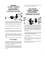
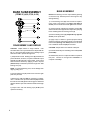
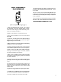
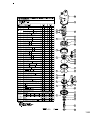
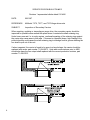
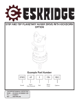
PART N U M B E R E X A M P L E: OUTPUT SHAFT MODEL BAIL BOSS MOTOR SUPPLIER 7835 5 5 MOTOR NO. F 17 R OPTIONS Series 78 Planetary Auger Drive Service & Repair Manual EFFECTIVE FOR: FROM S/N: 00001 - UP DATE: 04/24/86 - UP SM78>61599 SERIES 78 SERVICE MANUAL HYDRASYNC TM PLANETARY AUGER DRIVE This manual will assist in disassembly and assembly of major components for all Series 78 Planetary Auger Drives. Item numbers, indicated in parentheses throughout this manual, refer to the Eskridge Series 78 exploded parts breakdown drawings. Individual customer specifications (bail assembly, output shaft, hydraulic motor, etc.) may vary from exploded drawing and standard part numbers shown. If applicable, refer to individual customer drawing for details. LUBRICATION AND MAINTENANCE The oil should be changed after the first 50 hrs. of use and at 500 hr. intervals thereafter. Geardrives in auger drives require GL-5 grade EP 80/90 gear oil for lubrication. The manufacturer recommends that the unit be partially disassembled to inspect gears and bearings at 1000 hour intervals. OIL CAPACITY: 6.5 pints Proper oil level will measure to middle of primary planet gears when auger drive is in vertical position. WARNING: While working on this equipment, wear adequate protective clothing, hearing, eye, and respiratory protection. Use safe lifting procedures. UNIT DISASSEMBLY (Refer to exploded view drawing on page 7) 1) Scribe a diagonal line, from the bail (35) to the bearing carrier (4), across the outside of the auger drive to assure proper orientation of parts as they are re-assembled. 2) To drain oil, position unit on its side and remove oil plug (28) located in bearing carrier (4). To help ventilate oil while draining, loosen or remove oil plug (37) located in cover (1). Maximum drainage occurs when oil is warm. 6) Lift the primary planet carrier assembly out of the unit (includes items 7,10,12,14,19, & 23). 7) If sun gear (16) has not been removed from auger drive, do so now. (Sometimes the sun gear remains in the primary carrier (7).) 8) Remove primary ring gear (6) and o-ring (30). 9) Remove retaining ring (26) from end of output shaft (2). NOTE: Particular care should be taken when placing the unit in a position for servicing. Unit should be blocked up so that weight of the unit is resting on the base. This fixture must be secure so that the auger drive will not tip over during disassembly and assembly procedures. 10) Lift the secondary planetary assembly out of the unit (includes items 8,11,13,15,18, & 23). Use a puller if necessary. 3) Remove the twelve hex head cap screws (22) and hex flange nuts (24) from bail (35). Lift bail from unit. NOTE: There are no bolts retaining the major components together. Proceed with caution when moving the unit. 12) The unit is now disassembled into groups of parts. The area(s) requiring repair should be identified by thorough inspection of the parts after they have been cleaned and dried. Then refer to the appropriate group repair section below. 4) Remove the two cap screws (32) and lock washers (33) from hydraulic motor (34). Remove motor from unit. Check o-ring (31) for damage. 1. Primary Planet Carrier subassembly 2. Secondary Planet Carrier subassembly 3. Base subassembly 5) Remove the cover (1), input gear (9), and o-ring (30). 2 11) Remove secondary ring gear (5) and o-ring (30). PRIMARY PLANET CARRIER SUBASSEMBLY (ITEMS 7,10,12,14,19, & 23) DISASSEMBLY AND REPAIR 3) Drive three roll pins (23) through the carrier holes and into the planet shafts to retain the parts. SECONDARY PLANET CARRIER SUBASSEMBLY (ITEMS 8,11,13,15,17,18,23, & 26) DISASSEMBLY AND REPAIR Rotate planet gears (14) to check for abnormal noise or roughness in bearings (19) or planet shafts (10). If further inspection or replacement is required, proceed as follows. 1) Drive roll pins (23) completely into planet shafts (10). 2) Press or drive planet shafts (10) out of carrier (7). 3) Remove planet gears (14) and planet washers (12) from the carrier (7). 4) If the planet bearings (19) require replacement, press them out of the planet gears (14) and replace with new ones. 5) Check primary planet shafts (10) for any abnormal wear, especially ones where bearings needed to be replaced. If any abnormal wear is found, replace planet shafts. 6) Remove the roll pins (23) from the planet shafts (10). RE-ASSEMBLY 1) With planet washers (12) on both sides of the planet gear (14) and with bearings (19) installed, slide gear into the carrier (7). Insert the planet shaft (10) through the carrier, washers, and planet gear. As with the primary planet carrier, check for abnormal noise in the planet gears bearings (18) by rotating the planets and listen and feel for any noise or roughness. If further inspection or replacement is required, follow the same procedure as steps 1-6 of the primary planet carrier assembly. Substitute items as indicated: planet gears (15), planet bearings (18), planet shafts (11), washers (13), carrier (8). The inner bearing cone (17) cannot be removed from the carrier (8), without destroying the bearing. If this needs replacement, please consult the factory. Proceed with steps 1 through 3 of the primary planet carrier re-assembly. NOTE 1: Retaining ring (26) must be inserted into carrier (8) before it is installed in unit, as described in step number 2 of UNIT ASSEMBLY. NOTE 2: See page 8 service bulletin concerning the wear of secondary planet carriers (8). 2) Planet shafts (10) should be installed with chamfered end of 1/8 inch hole toward outside diameter of the carrier (7). This will aid in alignment of holes while inserting roll pins (23). 3 BASE SUBASSEMBLY (ITEMS 2,3,4,20,27,28, & 36) BASE ASSEMBLY NOTE: Press bearing cone onto output shaft by pressing on inner race only. DO NOT press on roller cage or it may damage bearing. 1) If outer bearing cone (27) was removed for replacement, press a new bearing cone (large end down as shown) onto the shaft until it seats against the shoulder. 2) Clean all foreign material from magnetic oil plug (28). Add a small amount of pipe thread compound to pipe plug before installing back into bearing carrier (4). 3) Place the bearing carrier (4) (output side up, opposite shown) on the press table. DISASSEMBLY AND REPAIR CAUTION: Output shaft is no longer retained. Care should be taken not to injure feet because output shaft can fall out. Care should also be taken not to damage output shaft when shaft is pressed through base. 1) Output shaft removal. Bearing carrier (4) should be set pinion side down, as shown, on a plate or table with output shaft (2) protruding through a hole in table. Press output shaft out bottom of base by applying a load to top end (internal end) of shaft until it passes through inner shaft bearing cone (17). NOTE: If reusing old bearing cone, do not damage roller cage by pulling on it. 2) If outer bearing cone (27) needs to be removed a gear puller may be used. 3) Remove the shaft seal (36) for inspection or replacement. Lubricate inner lip of new shaft seal (36) and slide the seal onto the shaft (2) until it fits snugly over shaft seal diameter with the open side toward the inside of the auger drive. 4) Inspect inner and outer bearing cups (20 & 3) and replace if necessary. 4 4) Apply a layer of lithium or general purpose bearing grease to surface of outer bearing cup (3). Insert the shaft into the base (bearing cone down) and use a soft hammer to install the shaft seal (36) into the base. CAUTION: Output shaft is not retained at this point. 5) Invert this assembly so it is standing on the shaft (on the press table). All subassembly service or repairs should be complete at this point. Continue on through UNIT ASSEMBLY to complete unit buildup. UNIT ASSEMBLY REASSEMBLING 13) Attach hydraulic motor (34) to mounting pad on cover (1) with two capscrews (32) and lock washers (33). Torque to 130 ft-lbs. 14) Line up scribe mark on bail assembly (35) with scribe mark on cover (1) and place bail over hydraulic motor (34). Install twelve cap screws (22) with hex flange nuts (24) and torque to 30 ft-lbs. 15) Fill to proper level, as specified on page 2, with EP 80/ 90 gear oil after unit is sealed with a brake and/or motor. THE AUGER DRIVE IS NOW READY TO USE. (Refer to exploded drawing on page 7) 1) When all subassemblies are complete, unit is ready to be assembled. Place lower assembly back on blocks, which were used during the initial disassembly procedures, for remaining unit build-up. Caution: Output shaft is not retained at this point. 2) Push retaining ring (26) into center of secondary planet carrier (8). 3) Install the secondary planet carrier (8) assembly by rotating it until carrier spline lines up with shaft spline. Begin pressing carrier onto shaft. 4) Before secondary carrier is fully seated, install retaining ring (26) onto end of output shaft (2). 5) Continue pressing secondary carrier until fully seated. Check retaining ring (26) to be sure it is in the ring groove. 6) Place a new o-ring (30) on the bearing carrier (4). Refering to scribe marks for proper orientation, install the secondary ring gear (5) onto the base. 7) Place a new o-ring (30) on the secondary ring gear (5) and install the primary ring gear (2). Refer to scribe marks for proper orientation. 8) Check to be sure retaining ring (25) is installed on sun gear (16). Slide the sun gear into the secondary planet carrier. 9) Install the primary carrier (7) by rotating until spline lines up with sun gear . It may be easier to install the sun gear (12) into the bottom of the primary carrier and then install primary carrier. 10) Slide the input gear (13) into the primary planet carrier. 11) Install a new o-ring (30) onto the cover (6) and position the cover with the proper orientation to the scribed line. 12) Install o-ring (31) onto the hydraulic motor (34). 5 PRODUCT WARRANTY ESKRIDGE, INC. (Eskridge) warrants to its original purchaser (Customer) that new component parts (Parts) sold by Eskridge to the Customer will be free of defects in material and workmanship and will conform to standard specifications set forth in current Eskridge sales literature or to any custom specifications of the Customer acknowledged in writing by Eskridge, SUBJECT TO THE FOLLOWING QUALIFICATIONS AND LIMITATIONS: 1) Prior to placing warranted Parts in service, the Customer shall provide proper storage such that foreign objects (e.g., rain or debris) cannot enter any Parts via entry ports which are normally closed during operation. 2) If Parts requiring motorized power for operation are received from Eskridge without a motor, documentation must be available indicating proper lubrication upon placement of the Parts in service. 3) The Customer must notify Eskridge in writing of any claim for breach of this warranty promptly after discovery of a defect and in any event prior to the termination of the warranty period, which shall commence when a unit is placed in service and shall expire upon the earlier of (i) the expiration of twelve (12) months from the date of Commencement of Service (as defined in Paragraph 4) (ii) the completion of one thousand (1,000) hours of service of the Parts (iii) the expiration of six (6) months after the expiration of any express warranty relating to the first item of machinery or equipment in which the Parts are installed or on which it is mounted, or (iv) the installation or mounting of the Parts in or on an item of machinery or equipment other than the first such item in which the Parts are installed or on which the Parts are mounted. 4) Parts shall be deemed to have been place in service (the Commencement of Service) at the time the machinery or equipment manufactured or assembled by the Customer and in which the Parts are installed or on which the Parts are mounted is delivered to the Customers dealer or the original end-user, which ever receives such machinery or equipment first. 5) This warranty shall not apply with respect to Parts which, upon inspection by Eskridge, show signs of disassembly, rework, modifications or improper installation, mounting, use or maintenance. 6) Eskridge makes no warranty in respect to hydraulic motors mounted on any Parts. Failure of any such motor will be referred to the motor manufacturer. 7) Claims under this warranty will be satisfied only by repair of any defect(s) or, if repair is determined by Eskridge in its sole, absolute and uncontrolled discretion to be impossible or impractical, by replacement of the Parts or any defective component thereof. No cash payment or credit will be made for defective materials or workmanship. IN NO EVENT SHALL ESKRIDGE BE LIABLE FOR INCIDENTAL OR CONSEQUENTIAL DAMAGES OF ANY KIND OR NATURE, WHICH DAMAGES ARE HEREBY EXPRESSLY DISCLAIMED. 8) From time to time, Eskridge may make changes in the component parts manufactured by it without incorporating such changes in the component parts previously shipped. Such changes shall not constitute an admission by Eskridge of any defects or problems with previously manufactured component parts. 9) All freight charges on Parts returned for warranty service are the responsibility of the Customer. THE FOREGOING WARRANTY IS THE SOLE WARRANTY MADE BY ESKRIDGE WITH RESPECT TO ANY PARTS, AND IS IN LIEU OF ANY AND ALL OTHER WARRANTIES, EXPRESSED OR IMPLIED. THERE ARE NO WARRANTIES WHICH EXTEND BEYOND THE DESCRIPTION ON THE FACE HEREOF. WITHOUT LIMITING THE GENERALITY OF THE FOREGOING, ESKRIDGE EXPRESSLY DISCLAIMS ANY IMPLIED WARRANTY OF MERCHANTABILITY OR FITNESS FOR ANY PARTICULAR PURPOSE, REGARDLESS OF ANY KNOWLEDGE ESKRIDGE MAY HAVE OF ANY PARTICULAR USE OR APPLICATION INTENDED BY THE PURCHASER. THE SUITABILITY OR FITNESS OF THE PARTS FOR THE CUSTOMERS INTENDED USE, APPLICATION OR PURPOSE AND THE PROPER METHOD OF INSTALLATION OR MOUNTING MUST BE DETERMINED BY THE CUSTOMER. WARRANTY RETURN POLICY 1) All Parts shall be returned freight prepaid. 2) Any Parts qualifying for warranty will be repaired with new Parts free of charge (except for freight charges as provided above). 3) If parts are found to be operable, you have two options: a. The Parts can be returned to you with a service charge for inspection, cleaning, and routine replacement of all rubber components and any other parts that show wear; or b. We can dispose of the Parts at the factory if you do not wish it to be returned. NOTE: Any order of Parts by customer shall only be accepted by Eskridge subject to the terms stated herein. Any purchase order forms used by Customer (to accept this offer to sell) which contain terms contrary to, different from, or in addition to the terms herein shall be without effect, and such terms shall constitute material alteration of the offer contained herein under K.S.A 84-2-207 (2)(b), and shall not become part of the contract regarding the sale of the Parts. 6 7SER SERVICE DIVISION BULLETIN #013 Revision 1 supersedes bulletin dated 01/14/86 DATE: 06/01/87 REFERENCE: All Model 71/76, 72/77, and 73/78 Auger drive units SUBJECT: Inspection of Secondary Carriers When repairing, updating or inspecting an auger drive, the secondary carrier should be inspected for possible wear around the spline where it contacts the shaft retaining ring. Under heavy use and / or in rocky regions, continual impacting of the retaining ring against the carrier may cause wear in this area. If it wears to a beveled shape, high loading in the pullout direction could cause the shaft retaining ring to dislodge from its groove allowing the hex shaft to pull out of the unit. If when inspected, the carrier is found to be worn to a bevel shape, the carrier should be replaced with carrier part number 71-004-0073. Units with serial numbers prior to 4900 should also have the hex output shaft replaced with the current production revision, part number 71-004-0513. 8 OTHER ESKRIDGE PRODUCTS PLANETARY GEARDRIVES SERIES TORQUE RATING MAX. INTERMITTENT 20/28 SERIES 50 SERIES 60 SERIES 100 SERIES 130 SERIES 150 SERIES 250 SERIES 600 SERIES 1000 SERIES 20,000-28,000 IN-LB 50,000 IN-LB 60,000 IN-LB 100,000 IN-LB 130,000 IN-LB 150,000 IN-LB 250,000 IN-LB 600,000 IN-LB 1,000,000 IN-LB MULTIPLE DISC BRAKES SERIES 90B 90BA 92B 93 95C 95W 98D TORQUE RATING SAE B SAE B ADJUSTABLE TORQUE SAE B LOW PROFILE FOR NICHOLS MOTORS SAE C SAE C WHEEL MOUNT SAE D PLANETARY AUGER DRIVES (DIGGERS) SERIES D50 76 77 78 75 TO 4,800 IN-LB TO 4,800 IN-LB TO 2,800 IN-LB TO 6,100 IN-LB TO 12,000 IN-LB TO 21,000 IN-LB TO 25,000 IN-LB TORQUE RATING MODELS 1500, 2500 & 5000 MODELS BA & BC, TWO SPEED MODELS BA, BC & BD MODELS 35 & 48, TWO SPEED MODELS TWO SPEED 1900 Kansas City Road Olathe, Kansas 66061 phone (913) 782-1238 fax (913) 782-4206 WEBSITE: www.eskridgeinc.com E-MAIL: [email protected] Your nearest Eskridge Distributor is: 1,500-5,000 8,000-12,500 6,000-12,500 9,000-12,500 16,500-20,000 FT-LB FT-LB FT-LB FT-LB FT-LB