1
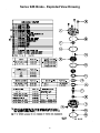
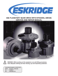
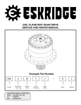
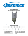
92B SERIES BRAKE SERVICE AND REPAIR MANUAL Example Part Number 92 B 2 A 3 G043 B Model Output Pilot Output Shaft Input Pilot Input Shaft Torque Options MODEL 92B SERVICE MANUAL MULTI DISC BRAKE This manual will assist in disassembling and assembling major components of all Model 92B Brakes. Item numbers, indicated in parentheses throughout this manual, refer to the Eskridge Model 92B exploded parts breakdown drawings. Individual customer specifications (mounting cases, output shafts, brake assemblies, etc.) may vary from the exploded drawing and standard part numbers shown. If applicable, refer to individual customer drawing for details. The Eskridge Model 92B series brake is manufactured for two specific types of holding torque requirements: the standard “fail-safe” requirement and the “slip protection” requirement. Both types are spring loaded (normally applied) with a hydraulic pressure required for release. All brakes are individually tested at the factory for function, leaks and static breakaway torque. Fail-safe type brakes are tested to be assured they are in excess of 110% of the fail-safe torque rating for the unit. A fail-safe brake should be used when the only requirment is a minimum static holding torque. A slip protection brake should be used where an accurate specified torque is required, such as a side load protection on a crane or overload protection in a drivetrain. These brakes are tested to be within +/- 10% of the slip protection rating for the unit. SPECIFICATIONS Maximum Pressure 4,000 PSI Maximum Continuous Pressure 4,000 PSI Maximum Speed 3,900 RPM Shaft Splines 30° involute, flat roof side fit per ANSI B92.1-1970 internal - class 7, external - class 5 Maximum Operating Temperature 170°F Volume of Oil to Release Brake 0.3 cu. in. Approximate Weight 20 lbs Breakaway torque may vary +/- 10% from specified ratings. Use of fluids other than ATF-F must be compatible with internal seals. Wet brake torque based on ATF-F fluid friction plate cavity. Use only mineral based hydraulic oil to release brake. CONTENTS Example Part Number ........................................................................................................................................1 Specifications .....................................................................................................................................................2 Installation...........................................................................................................................................................3 Disassembly .......................................................................................................................................................3 Assembly ............................................................................................................................................................4 Repair Kits ..........................................................................................................................................................4 Series 92B Brake - Exploded View Drawing ....................................................................................................5 Eskridge Product Warranty ...............................................................................................................................6 Warranty Return Policy ..........................................................................................................................6 The Eskridge Product Line ................................................................................................................................7 Planetary Gear Drives ............................................................................................................................7 Multiple Disc Brakes...............................................................................................................................7 Planetary Auger Drives, Anchor Drives & Diggers..............................................................................7 2 Installation Disassembly Note: Before beginning installation procedures, visually inspect brake mounting flanges and shaft splines for damage due to poor handling during shipping. If damage is excessive, do not use brake. 1) 2) Mount 92B brakes with (2) 1/2-13x1 capscrews through brake mounting flange. Torque bolts to 75 ft-lbs. On horizontal shaft mounting, one o-ring port should be oriented as close to the top as practical (bleeder port). Some installations may require that the brake be “released” so it can be rotated to align bolt holes. (See Step 4 below.) Remove plastic protective plug from brake pressure port and attach a pressure line with 7/16-20 UNF-2B straight thread o-ring fitting. 4) Apply low pressure (20–30 psi) to brake release port. Loosen hollow hex plug, opposite of pressure port, just enough to allow hydraulic fluid to bleed from cavity. After air has been bled from brake, tighten plug. Remove motor from brake. 2) Loosen (4) 1/2-13x1 12-point capscrews (8). Alternately, unscrew capscrews 1/2 turn at a time until all internal spring force is relieved. Remove cover (2). CAUTION: Do not clamp or otherwise retain cover (2) while removing cover bolts (8), since the brake is under high compressive spring load. Attach motor to input end of brake with appropriate sized bolts through motor flange and gasket to give approximately 1/2” thread engagement. Torque 1/2” bolts to 75 ft-lbs or 3/8” bolts to 32 ft-lbs. 3) 1) 3 3) Apply low pressure (20–30 PSI) to brake release port while holding one hand on top of piston (3) and springs (10). The air will force piston out of case. 4) Remove shaft (4). 5) Friction discs (11), separator plates (12) and spacers (5) may now be removed from case (1). Assembly Repair Kits Assembly should be in reverse order of disassembly, incorporating these additional instructions Due to the many combinations of torque and release pressures available for the Series 92B Brake, it is impossible to detail each style and supply a repair kit for each model. The information listed in this manual is representative of all Series 92B brakes. The repair kits listed below will work with all combinations of torque and release pressures, input mountings and friction plates. 1) Install shaft (4) by pushing shaft downward through bearing (7) and seal (18) until bearing shoulder on shaft is seated against bearing. 2) Friction pack [spacer (5), friction disc (11) and separator plate (12)] must be installed in exactly the same order as it was removed. There must always be a friction disc (11) on top and bottom ends of stack plates. If a separator plate (12) is placed next to the piston (3) or spacer (5), the unit will overheat and sieze. Be careful not to contaminate the friction surfaces with dirt, grease or fluid media* other than what was specified for your particular brake. It is entirely possible to have “extra” parts left over from the repair kits after maintenance is complete. If you are not sure about what is required for your brake and its configuration, please contact Eskridge’s salesdepartment. Friction Disc Kit, 92B NOTE: If installing new friction discs (11), soak all discs in specified fluid media for approximately 10 minutes before installation. 3) Pour fluid medium over the friction plates or until the fluid level is even with top friction disc (11). 4) If replacing piston o-rings, be sure o-rings (15 &16) are nearest each other with back up rings (13 &14) to the outside after installing onto piston (3). If back-up rings have concave face, that face must be towards o-ring. Gently slide piston (3) into case (1) until large o-ring (16) touches case. Press down firmly on piston using heel of both hands; this will squeeze o-rings into case and set piston (3) against friction plates. 92-016-1981 Friction Plates, 4 Separator Plate Kit, 92B 01-228-0010 92-016-1991 Separator Plates, 3 Seal Kit, 92B 01-228-0020 92-016-2011 O-Ring, Piston, 1 01-402-0630 O-Ring, Piston, 1 01-402-0640 O-Ring, Case Seal, 1 01-402-0650 Shaft, Seal, 1 01-405-0570 5) Insert springs (10) into piston (3). O-Ring, Mtr., SAE “B”, 1 01-402-0220 6) Install cover o-ring (17) around lip on case (1). Gasket, Mtr., SAE “A” 4 Bolt, 1 90-004-1061 7) Install thrust washer (7) onto shaft (4). Gasket, Mtr., SAE “A” 4 Bolt, 1 90-004-1081 8) Set cover (2) on top of springs and over input end of shaft (4). Start four cover bolts (8) through cover and into case with your fingers. Alternately tighten cover bolts 1/2 turn at a time until cover is tight against sace. Torque bolts to 80 ft-lbs. Gasket, Mtr. SAE “B” 2 Bolt, 1 90-004-1091 Master Rebuild Kit, 92 92-015-2051 (Non-Bronze) * Unless otherwise specified, Eskridge Series 92B Brakes use automatic transmission fluid (ATF Type F) as a fluid medium. ATF Dexron will give somewhat different torque characteristics. Some brakes are specifically designed to use hydraulic oil, gear lube or other fluid media. 4 Friction Disc Kit, Non-Bronze,1 92-016-1981 Seal Kit, 92B, 1 92-016-2011 Bearing, Output, 1 01-100-0240 Bearing, Input, 1 01-112-0310 Series 92B Brake - Exploded View Drawing 5 Eskridge Product Warranty ESKRIDGE, INC. (“Eskridge”) warrants to its original purchaser (“Customer”) that new component parts/units (“Units”) sold by Eskridge will be free of defects in material and workmanship and will conform to standard specifications set forth in Eskridge sales literature current at the time of sale or to any custom specifications acknowledged by written Customer approval of drawings, SUBJECT TO THE FOLLOWING QUALIFICATIONS AND LIMITATIONS: 1. Prior to placing Units in service, the Customer shall provide proper storage such that foreign objects (e.g., rain or debris) cannot enter any Units via entry ports which are normally closed during operation. 2. The Customer must notify Eskridge in writing of any claim for breach of this warranty promptly after discovery of a defect. The warranty period shall commence when a unit is placed in service and shall expire upon the earlier of a. the expiration of twelve (12) months from the date of Commencement of Service (as defined in Paragraph 4) b. the completion of one thousand (1000) hours of service of the Units c. the expiration of six (6) months after the expiration of any express warranty relating to the first item of machinery or equipment in which the Units are installed or on which it is mounted, or d. the installation or mounting of the Units in or on an item of machinery or equipment other than the first such item in which the Units are installed or on which the Units are mounted. 3. Units shall be deemed to have been placed in service (the “Commencement of Service”) at the time the machinery or equipment manufactured or assembled by the Customer and in which the Units are installed or on which the Units are mounted is delivered to the Customer’s dealer or the original end-user, which ever receives such machinery or equipment first. 4. This warranty shall not apply with respect to Units which, upon inspection by Eskridge, show signs of disassembly, rework, modifications, lack of lubrication or improper installation, mounting, use or maintenance. 5. Eskridge makes no warranty in respect to hydraulic motors mounted on any Units. Failure of any such motor will be referred to the motor manufacturer. 6. Claims under this warranty will be satisfied only by repair of any defect(s) or, if repair is determined by Eskridge in its sole, absolute and uncontrolled discretion to be impossible or impractical, by replacement of the Units or any defective component thereof. No cash payment or credit will be made for defective materials, workmanship, labor or travel. IN NO EVENT SHALL ESKRIDGE BE LIABLE FOR INCIDENTAL OR CONSEQUENTIAL DAMAGES OF ANY KIND OR NATURE, FOR WHICH DAMAGES ARE HEREBY EXPRESSLY DISCLAIMED. 7. From time to time, Eskridge may make design changes in the component Units manufactured by it without incorporating such changes in the component Units previously shipped. Such design changes shall not constitute an admission by Eskridge of any defects or problems in the design of previously manufactured component Units. 8. All freight charges on Units returned for warranty service are the responsibility of the Customer. 1. Any part/Unit(s) returned to Eskridge must be authorized by Eskridge with an assigned return (CSR) number. 2. All Units shall be returned freight prepaid. 3. Any Units qualifying for warranty will be repaired with new parts free of charge (except for freight charges to Eskridge as provided above). 4. If Units are found to be operable, you have two options: Warranty Return Policy a. The Units can be returned to you with a service charge for inspection, cleaning, and routine replacement of all rubber components and any other Units that show wear; b. We can dispose of the Unit(s) at the factory if you do not wish it to be returned. NOTE: Any order of Units by customer shall only be accepted by Eskridge subject to the terms stated herein. Any purchase order forms used by Customer (to accept this offer to sell) which contain terms contrary to, different from, or in addition to the terms herein shall be without effect, and such terms shall constitute material alteration of the offer contained herein under K.S.A 84-2-207 (2)(b), and shall not become part of the contract regarding the sale of the Units. The foregoing warranty is the sole warranty made by Eskridge with respect to any Units and is in lieu of any and all other warranties, expressed or implied. There are no warranties which extend beyond the description on the face hereof without limiting the generality of the foregoing, Eskridge expressly disclaims any implied warranty of merchantability or fitness for any particular purpose, regardless of any knowledge Eskridge may have of any particular use or application intended by the purchaser. The suitability or fitness of the Units for the customer’s intended use, application or purpose and the proper method of installation or mounting must be determined by the customer. 6 THE ESKRIDGE PRODUCT LINE PLANETARY GEAR DRIVES TORQUE RATING (IN-LB) SERIES MAX. INTERMITTENT 20 - SHAFT OUTPUT 28 - SHAFT OUTPUT 50 - SHAFT OUTPUT OR SPINDLE OUTPUT 65 - SHAFT OUTPUT 105 - SHAFT OUTPUT 130/133 - SHAFT OUTPUT OR SPINDLE OUTPUT 150 - SHAFT OUTPUT 250/252 - SHAFT OUTPUT OR SPINDLE OUTPUT 440 - SHAFT OUTPUT, SPINDLE OUTPUT OR WHEEL DRIVE 600 - SHAFT OUTPUT, SPINDLE OUTPUT OR WHEEL DRIVE 1000 - SHAFT OUTPUT, SPINDLE OUTPUT OR WHEEL DRIVE 20,000 50,000 50,000 65,000 105,000 130,000 150,000 250,000 440,000 600,000 1,000,000 MULTIPLE DISC BRAKES SERIES 10 - INTEGRAL BRAKE 90B 90BA 92B 93 (931 OR 932) 95C 98D FEATURES SAE B SAE B SAE B, ADJUSTABLE TORQUE SAE B, LOW PROFILE FOR NICHOLS MOTORS SAE C SAE D TORQUE RATING (IN-LB) TO 4,800 TO 4,800 TO 4,800 TO 2,800 TO 6,100 TO 12,000 TO 25,000 PLANETARY AUGER DRIVES, ANCHOR DRIVES & DIGGERS SERIES D50 76 77 78 75 D600 D1000 MODELS 1500, 2500 & 5000 BA & BC, 2-SPEED BA, BC & BD 35 & 48, 2-SPEED 38 & 51, 2-SPEED D600 D1000 TORQUE RATING (FT-LB) 1,500 - 5,000 8,000 - 12,500 6,000 - 12,500 9,000 - 12,500 16,500 - 20,000 50,000 83,000 P. O. Box 875 1900 Kansas City Road Olathe, KS 66051 Phone (913) 782-1238 Fax (913) 782-4206 [email protected] www.EskridgeInc.com