1
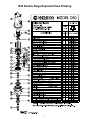
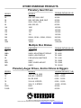
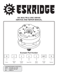
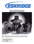
D50 PLANETARY AUGER DRIVE
SERVICE AND REPAIR MANUAL
Example Part Number
5005
2
1
F
54
Model
Shaft
Bail Boss
Motor
Supplier
Motor
Number
THIS SERVICE MANUAL IS EFFECTIVE
FROM: ..... S/N 29443, FEB. 1997
TO:........... S/N 58699, AUG. 2003
REF: ........ SMD50K-AB
D50 MODEL SERVICE MANUAL
SINGLE & DOUBLE PLANETARY AUGER DRIVES
This manual will assist in the disassembly and assembly of the above model Planetary Auger Drives. Item numbers, indicated in parentheses throughout this manual, refer to the exploded parts breakdown drawing. Individual customer specifications (mounting case,
output shaft, brake assy, etc.) may vary from exploded drawing and standard part numbers shown. If applicable, refer to individual customer drawing for details.
For any spare or replacement parts, contact your distributor or equipment manufacturer. Always try to have available the auger drive
unit part number, serial number and ate code on the serial tag. This information may be necessary for verification of any component part
numbers. Component part numbers and/or manufacturing lot numbers may be stamped on individual parts. This information may also
be helpful in identifying replacement components.
LUBRICATION & MAINTENANCE
Change the oil after the first50 hours of operation. Oil should be changed at 500 hour intervals thereafter. All gearboxes require a
GL-5 grade EP 80/90 gear oil for lubrication. Manufacturer also recommends that unit be partially disassembled to inspect gears and
bearings at 1000 hour intervals.
Model
Oil Capacity
Oil Level
Single Stage
2 pints / 0.95 liters
To horizontal centerline of gear drive
Double Stage
2.5 pints / 1.18 liters
To midway on upper/primary gear set
CONTENTS
Example Part Number .................................................................................................. 1
Lubrication & Maintenance.......................................................................................... 2
Before Disassembly ..................................................................................................... 3
Unit Disassembly Procedure....................................................................................... 3
Output Shaft Subassembly ................................................................................3
*Primary Planetary Subassembly ......................................................................3
Secondary Planetary Subassembly ..................................................................3
Case Subassembly .............................................................................................4
Unit Reassembly .......................................................................................................... 4
D50 Single Stage Exploded View Drawing................................................................. 6
D50 Double Stage Exploded View Drawing ............................................................... 7
D50 Double Stage Exploded View Drawing ............................................................... 8
Eskridge Product Warranty ......................................................................................... 9
Warranty Return Policy.......................................................................................9
Other Eskridge Products ........................................................................................... 10
Planetary Gear Drives.......................................................................................10
Multiple Disc Brakes .........................................................................................10
Planetary Auger Drives, Anchor Drives & Diggers ........................................10
2
Before Disassembly
In the D50 series, there are two types of units: single planetaries
without a primary carrier, and double planetaries which have a
primary planet carrier. Steps with an asterisk (*) apply only to the
double planetary model.
Unit Disassembly Procedure
3)
NOTE: Press only on inner race of bearing cone. DO NOT
press on outer roller cage of bearing or it will damage bearing.
*Primary Planetary Subassembly
All parts should be inspected as they are removed from unit.
Scribe across bail assembly (42), mounting case (1), ring gear (2),
and cover (3) joints on outside of gearbox to assure proper orientation of oil fill and drain plugs, motor mounting, etc., as the unit is
reassembled.
1)
Remove the six hex head cap screws (38) from bail assembly
(42). Lift bail assembly from unit.
2)
Remove hydraulic motor (41) from auger drive. Drain oil.
3)
Remove the twelve 7/16 x 4-1/2” hex cap screws (27) and
7/16 lockwashers (31), which retain cover (3) and ring gear
(2) to mounting case (1).
Press outer bearing cone (18) onto output shaft (4). With
small end of bearing cone pointing upward, start over internal
end of shaft and press until bearing is seated tightly against
shoulder.
Rotate primary planet gears (8) to check for any abnormal noises
or roughness in the primary planet bearings (25). At the same time,
inspect planet gears for any damage or worn teeth. If replacement
or further inspection is required, proceed as follows.
1)
Drive the spring pins (or roll pins) (30) completely into the
planet shafts (14) using a pin punch. Press planet shafts out
of carrier (6).
4)
Lift cover (3) off of unit and remove input gear (12) and input
thrust washer (26).
*5)
Primary planetary assembly is now ready for removal (includes items 6,8,14,17,25, and 30). Secondary sun gear
(11) is splined to primary carrier (6) and may come out when
removing planetary assembly. If not, remove sun gear.
NOTE: Support primary carrier (6) only while pressing planet
shafts.
2)
Slide planet gears (8) and primary planet washers (17) from
carrier (6).
6)
The secondary planetary assembly (includes items
5,7,13,15,16,24, and 29) is splined to the output shaft (4). It
may now be lifted, by hand, from output shaft spline.
3)
If any of the primary planet bearings (25) need replacing,
press them out of planet gears.
7)
Place unit on a press table with the output shaft (4) protruding
downward through a hole in the table. Unit should be supported only by mounting case (1). The only thing retaining
output shaft (4) at this point is the retaining ring (22). Remove
the retaining ring (22), spacer (23), and shims (10).
4)
Check primary planet shafts (14) for any abnormal wear, especially ones in which bearings needed to be replaced. If any
abnormal wear is found, replace planet shaft.
5)
CAUTION: Retaining ring is no longer retaining output shaft.
Take precautions if the unit is moved because the shaft may
fall out.
Punch remainder of sheared-off roll pins from carrier and
planet shafts. New roll pins are required if they are sheared
off.
6)
Press new primary planet bearings (25) into planet gears, if
required.
8)
7)
With a primary planet washer (17) on both sides of planet
gear and bearing installed, slide gear into carrier (6) and
insert primary planet shaft (14) through carrier, planet gear,
and washers. During planet shaft installation, align roll pin
hole in planet shaft with the roll pin hole in outside diameter
of carrier.
With output shaft down through centerhole in press table and
unit supported by case, press shaft out by applying press
load to top end of shaft (internal end) until it passes through
inner shaft bearing (19). Outer shaft bearing (18) will come
out of unit attached to shaft.
CAUTION: Care should be taken not to injure feet or damage
output shaft during this procedure.
The unit is now disassembled into groups of parts and/or subassemblies. The area requiring repair or service should be identified
by thorough inspection of the parts after they have been washed
in solvent.
1)
2)
NOTE: Inserting a 1/8” diameter punch in roll pin hole of planet
shaft will help in the alignment of holes between planet shaft
and carrier during step #7.
8)
Once holes are properly aligned, drive a roll pin (30) through
primary carrier and into planet shaft to retain parts. Use a
drift to drive roll pin flush to carrier and to prevent striking
planet gear teeth.
9)
Repeat same process for remaining gears.
Output Shaft Subassembly
If outer bearing cone (18) needs to be replaced, it will need
to be pressed off of output shaft. Also inspect inner bearing
cone (19). Shaft was pressed through inner bearing cone
during shaft removal procedure; it is located in mounting case
seated inside the inner bearing cup (21).
Secondary Planetary Subassembly on next page.
Lubricate inner lip of new shaft seal (34) and turn until open
side of seal is up. Slide seal onto output shaft until it fits snug
over shaft seal diameter.
Steps with an asterisk (*) apply only to the double planetary model.
3
Secondary Planetary Subassembly
Follow same procedures as that for the Primary Planetary Subassembly, only substitute item numbers as indicated. Secondary
carrier (5), secondary planet gear (7), secondary planet shaft (13),
carrier cup washer (15), secondary plant washer (16), secondary
planet bearing (24), secondary roll pin (29).
Case Subassembly
6)
Apply a layer of lithium bearing grease to inner bearing cup
(21) surface.
7)
Install inner bearing cone (19) (small end down) over internal end of output shaft. Press bearing on slowly until it is just
seated against bearing cup (21). With a slight press load still
applied, rotate case (1) by hand to ensure roller bearings are
rotating evenly and smoothly. Inner bearing cone (18) may
require additional press load to reach proper bearing preload.
If roller bearings are seated properly, continue on to set and
check bearing preload.
SHAFT BEARING PRELOAD: Proper shaft bearing preload is
achieved when torque required to rotate case is 50 to 80 in-lbs.
This rolling torque is equal to a force of approximately 11 to 18
lbs if pulling on mounting case flange to rotate case (1). This
may be determined by feel or by using a fish scale or similar
measuring device to check rolling torque.
8)
Install shims (10) over internal end of output shaft (4). Shims
should slide all the way down to outer bearing cone (18),
where they will rest. The same number (quantity) of shims
removed from unit during disassembly should be returned.
Follow shims with bearing spacer (23). Spacer will sit directly
on top of bearing shims.
NOTE: Quantity of shims (10) may vary from unit to unit. Bearing preload, set at the factory, determines quantity of shims.
1)
2)
Inspect inner and outer bearing cups (20, 21). If cups are
damaged, the cups and case (1) may need replacement.
Contact Eskridge if you have questions.
Clean all foreign material from magnetic oil plug (32) located
on bottom of mounting case (1). Add a small amount of pipe
thread compound to pipe plug before installing it back into
case.
9)
Install a new retaining ring (22) onto output shaft.
10)
Lightly grease a new o-ring (33) and install it into o-ring
groove in case (1). Assemble ring gear (2) to case (1). Refer
back to scribe marks made across external joints of gearbox
prior to Disassembly Procedure. Line up scribe marks between ring gear and case to give correct hole alignment.
NOTE: Be certain that o-ring (33) stays seated in groove
during step #10.
11)
Unit Reassembly
1)
Start with case assembly (1). Turn case upside down and position on press table. Case pilot diameter should be pointing
upward with outer bearing cup (20) exposed. Apply a layer of
lithium bearing grease to bearing cup surface.
2)
Invert output shaft assembly (4), retaining ring groove end
down, and carefully lower into case (1) until the shaft’s outer
bearing cone (18) is seated against outer bearing cup (20).
3)
Press shaft seal (34) into case until it is flush with bottom of
pilot diameter. Use a press fixture, if possible, to avoid distorting seal. If press fixture is not available, a hammer and
flat-ended drift may be used by tapping outer edge of seal
lightly and alternating sides.
4)
Stand unit assembly upright on output shaft.
CAUTION: The only thing holding output shaft and case together at this point is the tightness in fit of the shaft seal. Securely and cautiously turn unit upright, not allowing case and
shaft to separate.
5)
Install secondary carrier assembly into unit. Carrier assembly should be installed with hub side down (24 tooth spline).
Rotate carrier assembly back and forth to mesh secondary
planet gear teeth (7) with ring gear (2) teeth. Once teeth
mesh, let secondary carrier slide down until it contacts with
output shaft spline. The carrier splined hub (5) should spline
onto output shaft (4). Carrier hub will rest on top of retaining
ring (22) when splines are fully engaged. Check to be certain
carrier cup washer (15) is installed.
*12) Turn primary carrier assembly upside down so that splined
end of carrier (6) is up. Insert splined end of secondary sun
gear (11) into carrier spline until fully engaged. Install carrier
assembly into unit, sun gear down. Sun gear teeth will mesh
with secondary planet gears, and primary planet gear teeth
(8) will mesh with ring gear (2).
13)
Put input thrust washer (26) over step of input gear (12). Insert input gear into unit so that teeth mesh with planet gears.
14)
Grease a new o-ring (33) and install it into bottom of cover
(3). Refer back to scribe marks made across external joints
prior to Disassembly Procedure. Line up scribe marks between cover and ring gear (2) so that orientation of motor
mount holes and oil plug are back to their original positions.
NOTE: Be certain o-ring (33) stays seated in cover during step
#15.
While holding output shaft (4) with one hand, rotate case (1)
to be certain it turns freely and smoothly. The slight resis- 15) Install all twelve of the 7/16 lockwashers (31) and the 7/16
tance felt, if any, is due to shaft seal load (drag) on output
hex capscrews (27) and torque to 70 ft-lbs.
shaft.
Steps with an asterisk (*) apply only to the double planetary model.
4
16)
Fill unit with 2.5 pints of a GL-5 grade EP 80/90 gear oil.
Proper oil level will measure to middle of primary planet gears
(8).
17)
Install motor (41) with gasket (35), using hex head cap
screws (39) and lockwashers (36). Torque bolts to 55 ft-lbs.
18)
Lift bail assembly (42) onto planetary unit. Align access hole
with motor ports. Secure with six hex head capscrews (38),
lockwashers (36) and nuts (37). Torque to 55 ft-lbs.
THE AUGER DRIVE IS NOW READY FOR USE.
5
D50 Single Stage Exploded View Drawing
6
D50 Double Stage Exploded View Drawing
7
D50 Double Stage Exploded View Drawing
8
Eskridge Product Warranty
ESKRIDGE, INC. (“Eskridge”) warrants to its original purchaser (“Customer”) that new component parts/units (“Units”) sold by Eskridge
will be free of defects in material and workmanship and will conform to standard specifications set forth in Eskridge sales literature current
at the time of sale or to any custom specifications acknowledged by written Customer approval of drawings, SUBJECT TO THE FOLLOWING QUALIFICATIONS AND LIMITATIONS:
1.
Prior to placing Units in service, the Customer shall provide proper storage such that foreign objects (e.g., rain or debris) cannot
enter any Units via entry ports which are normally closed during operation.
2.
The Customer must notify Eskridge in writing of any claim for breach of this warranty promptly after discovery of a defect. The warranty period shall commence when a unit is placed in service and shall expire upon the earlier of
a.
the expiration of twelve (12) months from the date of Commencement of Service (as defined in Paragraph 4)
b.
the completion of one thousand (1000) hours of service of the Units
c.
the expiration of six (6) months after the expiration of any express warranty relating to the first item of machinery or equipment
in which the Units are installed or on which it is mounted, or
d.
the installation or mounting of the Units in or on an item of machinery or equipment other than the first such item in which the
Units are installed or on which the Units are mounted.
3.
Units shall be deemed to have been placed in service (the “Commencement of Service”) at the time the machinery or equipment
manufactured or assembled by the Customer and in which the Units are installed or on which the Units are mounted is delivered to
the Customer’s dealer or the original end-user, which ever receives such machinery or equipment first.
4.
This warranty shall not apply with respect to Units which, upon inspection by Eskridge, show signs of disassembly, rework, modifications, lack of lubrication or improper installation, mounting, use or maintenance.
5.
Eskridge makes no warranty in respect to hydraulic motors mounted on any Units. Failure of any such motor will be referred to the
motor manufacturer.
6.
Claims under this warranty will be satisfied only by repair of any defect(s) or, if repair is determined by Eskridge in its sole, absolute
and uncontrolled discretion to be impossible or impractical, by replacement of the Units or any defective component thereof. No
cash payment or credit will be made for defective materials, workmanship, labor or travel. IN NO EVENT SHALL ESKRIDGE BE LIABLE FOR INCIDENTAL OR CONSEQUENTIAL DAMAGES OF ANY KIND OR NATURE, FOR WHICH DAMAGES ARE HEREBY
EXPRESSLY DISCLAIMED.
7.
From time to time, Eskridge may make design changes in the component Units manufactured by it without incorporating such
changes in the component Units previously shipped. Such design changes shall not constitute an admission by Eskridge of any
defects or problems in the design of previously manufactured component Units.
8.
All freight charges on Units returned for warranty service are the responsibility of the Customer.
1.
Any part/Unit(s) returned to Eskridge must be authorized by Eskridge with an assigned return (CSR) number.
2.
All Units shall be returned freight prepaid.
3.
Any Units qualifying for warranty will be repaired with new parts free of charge (except for freight charges to Eskridge as provided
above).
4.
If Units are found to be operable, you have two options:
Warranty Return Policy
a.
The Units can be returned to you with a service charge for inspection, cleaning, and routine replacement of
all rubber components and any other Units that show wear;
b.
We can dispose of the Unit(s) at the factory if you do not wish it to be returned.
NOTE: Any order of Units by customer shall only be accepted by Eskridge subject to the terms stated herein. Any purchase order forms
used by Customer (to accept this offer to sell) which contain terms contrary to, different from, or in addition to the terms herein shall be
without effect, and such terms shall constitute material alteration of the offer contained herein under K.S.A 84-2-207 (2)(b), and shall not
become part of the contract regarding the sale of the Units.
The foregoing warranty is the sole warranty made by Eskridge with respect to any Units and is in lieu of any and all other warranties,
expressed or implied. There are no warranties which extend beyond the description on the face hereof without limiting the generality of
the foregoing, Eskridge expressly disclaims any implied warranty of merchantability or fitness for any particular purpose, regardless of
any knowledge Eskridge may have of any particular use or application intended by the purchaser. The suitability or fitness of the Units
for the customer’s intended use, application or purpose and the proper method of installation or mounting must be determined by the
customer.
9
OTHER ESKRIDGE PRODUCTS
Planetary Gear Drives
TORQUE RATING (IN-LB)
SERIES
MODELS
20
28
50
65
100
105
130
150
250
20B, 20P, 20LB, 20LP
28B, 28P, 28M, 28LB, 28LP
50K/L, 50LG, 50N
60B, 60E, 60L
100E
105E
130
150
250K/L, 251K/L, 252K/L, 253K/L
20,000
50,000
50,000
60,000
100,000
100,000
130,000
150,000
250,000
600
1000
600K/L
100K/L
600,000
1,000,000
MAX. INTERMITTENT
Multiple Disc Brakes
SERIES
90B
90BA
92B
93
95C
95W
98D
FEATURES
SAE B
SAE B, ADJUSTABLE TORQUE
SAE B, LOW PROFILE
FOR NICHOLS MOTORS
SAE C
SAE C WHEEL MOUNT
SAE D
TORQUE RATING (IN-LB)
TO 4,800
TO 4,800
TO 2,800
TO 6,100
TO 12,000
TO 21,000
TO 25,000
Planetary Auger Drives, Anchor Drives & Diggers
SERIES
D50
76
77
78
75
D600
D1000
MODELS
1500, 2500 & 5000
BA & BC, 2-SPEED
BA, BC & BD
35 & 48, 2-SPEED
38 & 51, 2-SPEED
D600
D1000
TORQUE RATING (FT-LB)
1,500 - 5,000
8,000 - 12,500
6,000 - 12,500
9,000 - 12,500
16,500 - 20,000
50,000
83,000
P. O. Box 875 n 1900 Kansas City Road n Olathe, KS 66051
Phone (913) 782-1238 n Fax (913) 782-4206 n [email protected] n www.EskridgeInc.com